

Page 1
Service Manual
[General]
Di152/Di183
Page 2

INDEX (GENERAL)
GENERAL
MECHANICAL/ELECTRICAL
Page 3

GENERAL
14413
Page 4

CONTENTS
1. SPECIFICATION .............................................................................................G-1
2. PRECAUTIONS FOR INSTALLATION .................................... ........................G-5
2-1. Installation Site ........................................................................................G-5
2-2. Power Source ..........................................................................................G-5
2-3. Grounding ................................................................................................G-5
3. PRECAUTIONS FOR USE ....................... ........................... ........................... .G-6
3-1. To ensure that the copier is used in an optimum condition .....................G-6
3-2. Operating Environment ............................................................................G-6
3-3. Power Requirements ............................................................................... G- 6
3-4. Note ......................................................................................................... G-6
4. HANDLING OF CONSUMABLES ............................. ............... ........................G-7
5. OTHER PRECAUTIONS ................. ............................ ........................... .........G-8
6. SYSTEM OPTIONS .........................................................................................G-9
i
Page 5
1. SPECIFICATION
TYPE
ORIGINAL SCANNING SYSTEM
PHOTOCONDUCTOR
COPYING SYSTEM
RESOLUTION
PAPER FEEDING SYSTEM
EXPOSURE SYS TEM
DEVELOPING SYSTEM
CHARGING SYSTEM
IMAGE TRANSFER SYSTEM
PAPER SEPARATING SYSTEM
FUSING SYSTEM
PAPER DISCHARGING SYSTEM
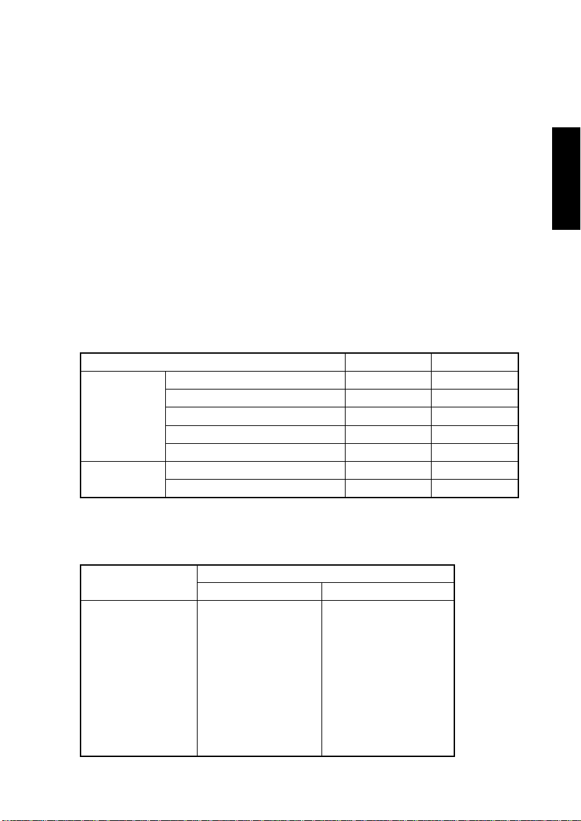
MAX. ORIGINAL SIZE
COPY MEDIUM
Paper Source Drawer Manual Bypass
Plain Paper (60 to 90 g/m
Transparencies
Type
Dimensions
MULTIPLE COPIES
WARMING-UP TIME
FIRST COPY TIME
CONTINUOUS COPY SPEED (copies/min)
Size
A4C
A4L
A3L
B4L
B5C
B5L
8-1/2 × 11C
8-1/2 × 11L
11 × 17L
8-1/2 × 14L
11 × 14
Thick Paper (91 to 157 g/m
Recycled Paper (60 to 90 g/m
Maximum (Width × Length) 297 × 432 mm 297 × 432 mm
Minimum (Width × Length) 90 × 140 mm 90 × 140 mm
:
Console/Desktop Type
:
CCD Line Sensor
:
Organic Photoconductor
:
Electrostatic Dry Powdered Image T r ansfer to Plain
Paper with a Laser
:
600 × 600 dpi
:
2-way system
Manual Bypass...Single
Drawer................250 Sheets
:
Mirror Scanning
:
MT-HG System
:
Comb Electrode (1) DC Negative Corona with
Scorotron System
:
Roller Image Transfer
:
Paper Separator Fingers and Charge Neutralizing
Plate
:
Heat Roller
:
Charge Neutralizing Brush
:
A3L, 11 × 17
Postcards
:
1 to 99
:
30 sec. or less (23, Rated Voltage)
:
7 sec. or less (A4C, Drawer, full size mode)
Di152 Di183
15
12
9
10
16
13
15
12
9
10
10
2
)
2
)
2
)
Speed
❍❍
❍❍
❍❍
❍❍
❍❍
18
14
10
12
20
15
18
14
10
12
12
G-1
Page 6

ZOOM RATIOS
Metric Inch
Full Size 100 % 100 %
200 %
Fixed
Enlargement
Reduction
Variable 50 % to 200 % (in 1 % increments)
141 %
115 %
81 %
70 %
50 %
200 %
129 %
121 %
78 %
64 %
50 %
LENS
EXPOSURE LAMP
POWER/CURRENT CONSUMPTION (copier only)
Exposure Lamp
(Rating)
24 V
14.4 W
POWER REQUIREMENTS : 110 V, 120 V, 127 V, 220 V to 240 V, 50/60 Hz
ENVIRONMENTAL CONDITIONS
Temperature 10 to 30 °C with a fluctuation of 10 °C or less per hour
Humidity 15 to 85 % RH with a fluctuation of 10 % RH or less per hour
Ambient Illumination 3,000 lux or less
Levelness 1° (1.75 mm/100 mm)
COPIER DIMENSION
COPIER WEIGHT
Fusing Roller
Heater Lamp
::Through Lens
Fluorescent Lamp
(Rating)
900 W
::W ...590 mm (23-1/4)
D....611 mm (24)
H....487 mm (19-1/4)
39 kg (86 lb)
Max. Power
Consumption
(full system)
110 V: 970 W
120 V: 1090 W
127 V: 1180 W
220 V: 990 W
230 V: 1050 W
240 V: 1120 W
Max. Current
Consumption
(full system)
110 V: 8.9 A
120 V: 9.1 A
127 V: 9.3 A
220 V: 4.5 A
230 V: 4.6 A
240 V: 4.7 A
G-2
Page 7

Multiple Bypass (MB-5): option
TYPE
INSTALLATION
COPY PAPER TYPE
Plain Paper (60 to 90 g/m
Transparencies 20 sheets
Type
Thick Paper (91 to 157 g/m
Recycled Paper (60 to 90 g/m
Dimensions
Size
Maximum (Width × Length) 297 × 432 mm
Minimum (Width × Length) 90 × 140 mm
A3L, B4L, FLS, A4L, A4C, B5L, B5C, A5C ,11 × 17, 11 × 14, 8-1/2 × 14,
8-1/2 × 11L, 8-1/2 × 11C, 8-1/2 × 5-1/2
DOCUMENT ALIGNMENT
CAPACITY
POWER REQUIREMENTS
MAX. POWER CONSUMPTION
DIMENSIONS
WEIGHT
OPERATING ENVIRONMENT
::Multiple Bypass
Mounted on the copier
2
)
2
)
50 sheets
20 sheets
Postcards 20 sheets
2
)
Center
:
:
50 sheets (80 g/m
:
DC24 V, DC5 V (supplied from copier)
:
9 W or less
:
W...245 mm (9-3/4)
2
)
50 sheets
D....435 mm (17-1/4)
H....137 mm (5-1/2)
:
2.7 kg (6 lb)
:
Same as copier
G-3
Page 8

Job Tray (JS-202): option
TYPE
INSTALLATION
::Multiple Bypass
Mounted on the copier
CAPACITY
Exit Tray
of the machine
1Stacking height up
Plain Paper (60 to 90 g/m
150 sheets (A4C/L)
2
75 sheets
)
(except A4C/L)
to 22 mm
100 sheets (A4C/L)
50 sheets
(except A4C/L)
Transparencies
Type
Thick Paper (91 to 157 g/m
2
)
20 sheets 10 sheets
Postcards
Stacking height up to
Recycled Paper (60 to 90 g/m
150 sheets (A4C/L)
2
75 sheets
)
(except A4C/L)
22 mm
100 sheets (A4C/L)
50 sheets
(except A4C/L)
Dimensions
Maximum (Width × Length) 297 × 432 mm
Minimum (Width × Length) 90 × 140 mm 140 × 140 mm
Exit Tray by Application Mode
Application Mode
Exit Tray
of the machine
Job Tray
Fax and Copier Copier Fax
Printer and Copier Copier Printer
Fax, Copier and Printer Copier Fax and Printer
Job Tray
POWER REQUIREMENTS : DC24 V, DC5 V (supplied from copier)
Shifting Unit (OT-103): option
TYPE
INSTALLATION
POWER REQUIREMENTS
:
Multiple Bypass
:
Mounted on the copier
:
DC24 V, DC5 V (supplied from copier)
G-4
Page 9

2. PRECAUTIONS FOR INSTALLATION
2-1. Installation Site
To ensure safety and utmost performance of the copier, the copier should NOT be used in a
place:
• Where it will be subjected to extremely high or low temperature or humidity.
• Where it will be subjected to sudden fluctuations in either temperature or humidity.
• Which is exposed to direct sunlight.
• Which is in the direct air stream of an air conditioner, heater, or ventilator.
• Which has poor ventilation or is dusty.
• Which does not have a stable, level floor or where it will receive undue vibration.
• Which is near any kind of heating device.
• Which is near volatile flammables (thinner, gasoline, etc.).
• Where it may be splashed with water.
• Which puts the operator in the direct stream of exhaust from the copier.
• Where ammonia gas might be generated.
2-2. Power Source
• If any other electrical equipment is sourced from the same power outlet, make sure that
the capacity of the outlet is not exceeded.
• Use a power source with little voltage fluctuation.
• Never connect by means of a multiple socket any other appliances or machines to the
outlet being used for the copier.
• Ensure that the copier does not ride on the power cord or communication cable of other
electrical equipment, and that it does not become wedged into or underneath the mechanism.
• Make the following checks at frequent intervals:
✽
Is the power plug abnormally hot?
✽
Are there any cracks or scrapes in the cord?
✽
Has the power plug been inserted fully into the outlet?
✽
Does something, including the copier itself, ride on the power cord?
Use an outlet with a capacity of 110 to 127 V, 15 A or more. 220 to 240 V, 10 A or more.
2-3. Grounding
• Always ground the copier to prevent receiving electrical shocks in the case of electrical
leakage.
• Connect the ground wire to the ground terminal of the outlet or a grounding contact which
complies with the local electrical standards.
• Never connect the ground wire to a gas pipe, the ground wire for a telephone, lightning
arrester, or a water pipe for fear of fire and electrical shock.
G-5
Page 10

3. PRECAUTIONS FOR USE
3-1. To ensure that the copier is used in an optimum condition
• Never place a heavy object on the copier or subject the copier to shocks.
• Insert the power plug all the way into the outlet.
• Do not attempt to remove any panel or cover which is secured while the copier is making
copies.
• Do not turn OFF the copier while it is making copies.
• Provide good ventilation when making a large number of copies continuously.
• Never use flammable sprays near the copier.
• If the copier becomes inordinately hot or produces abnormal noise, turn it OFF and
unplug it.
• Do not turn ON the power switch at the same time when you plug the power cord into the
outlet.
• When unplugging the power cord, do not pull on the cord; hold the plug and pull it out.
• Do not bring any magnetized object near the copier.
• Do not place a vase or vessel containing water on the copier.
• Be sure to turn OFF the power switch at the end of the workday or upon power failure.
• Use care not to drop paper clips, staples, or other small pieces of metal into the copier.
3-2. Operating Environment
The operating environmental requirements of the copier are as follows.
• Temperature: 10 to 30 °C
• Humidity: 15 to 85 % RH
• Rate of temperature change: 10 °C/h
• Rate of humidity change: 10 % RH/h
3-3. Power Requirements
The power source voltage requirements are as follows.
• Voltage fluctuation: AC110 to 127 V/220 to 240 V ± 10 %
(copying performance assured)
• Frequency fluctuation: 50/60 Hz ± 0.3 %
+10 %/-15 % (paper feeding performance assured)
3-4. Note
• It is prohibited to copy paper and hard currencies, government securities, and municipal
bonds (even when they are stamped as “Sample”).
• For fear of infringement of copyright, it is also prohibited to copy copyrighted works,
including books, music, works of art, maps, drawings, motion pictures, and photos except
when the copy is to be used only personally.
G-6
Page 11

4. HANDLING OF CONSUMABLES
Before using any consumables, always read the label on its container carefully.
• Paper can be easily damaged by dampness. To prevent absorption of moisture, store
paper, which has been removed from its wrapper but not loaded in the drawer, in a
sealed plastic bag in a cool, dark place.
• Keep consumables out of the reach of children.
• Do not touch the PC Drum with bare hands.
• The same sized paper is of two kinds, short grain and long grain. Short grain paper
should only be fed through the copier crosswise, long grain paper should only be fed
lengthwise.
• If your hands become soiled with toner, wash them with soap and water.
• Do not throw away any used consumables (PC Drum, starter, toner, etc.). They are to be
collected.
• Do not burn, bury in the ground, or throw into the water any consumables (PC Drum,
starter, toner, etc.).
• Do not store consumables in a place which:
✽
Is hot and humid.
✽
Is subject to direct sunlight.
✽
Has an open flame nearby.
G-7
Page 12

5. OTHER PRECAUTIONS
Use the following precautions when performing service jobs for a copier that uses a laser.
• When a service job needs to be performed in the laser beam path, such as when working
around the printerhead or PC Drum, be sure first to unplug the power cord of the copier
from the outlet.
• If the job requires that the power cord be left plugged in, observe the following precautions.
1. Take off your watch, ring and any other reflective object and wear laser protective gog-
gles.
2. Keep users away from the job site.
3. Do not bring a highly reflective tool into the laser beam path during the service job.
G-8
Page 13
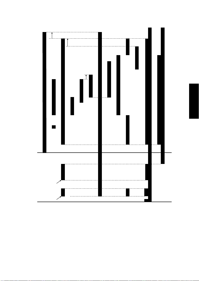
6. SYSTEM OPTIONS
1
2
4021O009AA
3
1144M172AC
4021O010AA
7
4
4695U011AA
4021O013AB
6
4021O063AA
4021O012AA
5
1. Plug-In Counter
2. Original Cover OC-5
3. Automatic Document Feeder AF-10
4. Multiple Bypass MB-5
5. Copy Desk
6. Paper Feed Cabinet PF-120
7. Data Terminal DT- 201
8. Job Tray JS-202
(Illustration none)
4021O014AA
9. Sifting Unit OT-103
(Illustration none)
10. Memory M16-4, M32-3
(Illustration none)
11. Mechanical Counter CNT1
(Illustration none)
G-9
Page 14

MECHANICAL/
ELECTRICAL
14413
Page 15

CONTENTS
1. CROSS SECTIONAL VIEW ............................................................................M-1
2. COPY PROCESS ............................................................................................M-2
3. DRIVE SYSTEM ..............................................................................................M-4
4. SEQUENTIAL EXPLANATION ................. ........................... ............................M-5
5. WATCHDOG FUNCTION (CPU OVERRUN MONITOR) ................................M-6
5-1. Watchdog Function Post-Processing . ......................................................M-6
6. IMAGE STABILIZATION SYSTEM ..................................................................M-7
7. IMAGING UNIT (I/U) ........................................................................................M-8
7-1. Imaging Unit (IU) Drive Mechanism .........................................................M-9
8. PC DRUM SECTION .......................................................................................M-10
8-1. PC Drum Drive Mechanism ..................................................................... M-10
8-2. Grounding of the PC Drum ................. .... .... .. .... ......... .... .. .... ......... .... .... .. .M-11
9. PC DRUM CHARGING SECTION ...................................................................M-12
10. IMAGE READING SECTION ...........................................................................M-13
10-1.Image Processi ng Pr o cess ............. ....................................... ..................M-14
10-2.Exposure Components Section ...............................................................M-15
10-3.Scanner and Mirrors Carriage Movement Mechanism ............................ M-16
(1) Scanner Movement Mechanism ......................................................M-16
(2) 2nd/3rd Mirrors Carriage Movement Mechanism ............................M-16
10-4.Scanner Motor Drive Control ...................................................................M-17
11. MEMORY STORAGE IMAGE PROCESSING SYST EM .................................M-18
11-1.Laser Exposure Process .........................................................................M-19
12. DEVELOPING UNIT SECTION .............................. ............................ .............M-20
12-1.Developing Unit Drive Mechanism ..........................................................M-21
12-2.Sleeve/Magnet Roller ..............................................................................M-22
12-3.Developing Bi a s ..................... ........................................ ..........................M-22
12-4.ATDC Sensor ................................... ........................... ............... .............M-23
(1) ATDC Sensor Automatic Adjustment ..............................................M-23
12-5.Toner Replenishing Mechanism ..............................................................M-24
12-6.Toner Replenishing Control .....................................................................M-25
12-7.T/C Recovery Mode .................................................................................M-26
12-8.Toner Bottle Home Position Detection Mechanism .................................M-27
13. PAPER TAKE UP/FEED SECTION .................................................................M-28
13-1.Drawer In Position Detection ...................................................................M-29
13-2.Paper Empty Detection Mechanism ........................................................M-29
13-3.Paper Lifting Plate ...................................................................................M-30
13-4.Universal Tray Paper Size Detection Mechanism ...................................M-30
13-5.Paper Take Up Mechanism .....................................................................M-32
(1) Paper Separating Mechanism ......................................................... M-32
13-6.Paper Take Up Control ............................................................................M-33
(1) Paper Take Up Retry Control ..........................................................M-33
14. MANUAL BYPASS SECTION .........................................................................M-34
14-1.Paper Take Up Drive Mechanism ............................................................M-34
14-2.Paper Detection Mechanism ...................................................................M-34
14-3.Manual Feed Take Up Control ........................................................... .... .M-35
15. MULTIPLE BYPASS SECTION .......................................................................M-36
i
Page 16

15-1.Paper Take Up Drive Mechanism ............................................................M-36
15-2.Paper Take-Up Mechanism .....................................................................M-37
15-3.Paper Empty Detection Mechanism ........................................................M-38
15-4.Paper Take Up Control ............................................................................M-38
15-5.Paper Take Up Retry Control ..................................................................M-39
16. IMAGE TRANSFER AND PAPER SEPARATION SECTION ..........................M-40
17. PC DRUM CLEANING SECTION ....................................................................M-41
18. MAIN ERASE SECTION .................................................................................. M-42
19. FUSING UNIT SECTION .................................................................................M-43
19-1.Fusing Unit Drive Mechanism ..................................................................M-44
19-2.Fusing Rollers Pressure Mechanism .......................................................M-44
19-3.Fusing Temperature Control ....................................................................M-45
19-4.CPM Control ............................................................................................M-45
20. JOB TRAY (JS-202): Option ............................................................................M-46
20-1.Tray Selecting Mechanism ......................................................................M-47
20-2.Tray-Full Detecting Mechanism ...............................................................M-48
20-3.Job Tray Paper Detecting Mechanism ....................................................M-48
21. SHIFTING UNIT (OT-103): Option ..................................................................M-49
21-1.Exit Position Shifting Mechanism ............................................................M-50
22. OTHER MECHANISM ................................ ........................... ..........................M-52
22-1.Cooling Mechanism . . ...............................................................................M-52
(1) Power Supply Section Cooling Mechanism .....................................M-52
(2) Fusing Section Cooling Mechanism ................................................M-53
ii
Page 17

1. CROSS SECTIONAL VIEW
1
2
5
1. IR Section
2. Fusing Unit
3. Imaging Unit
3
4
4. Paper Take-Up/Feed Section
5. PH Section
4021M001AA
M-1
Page 18
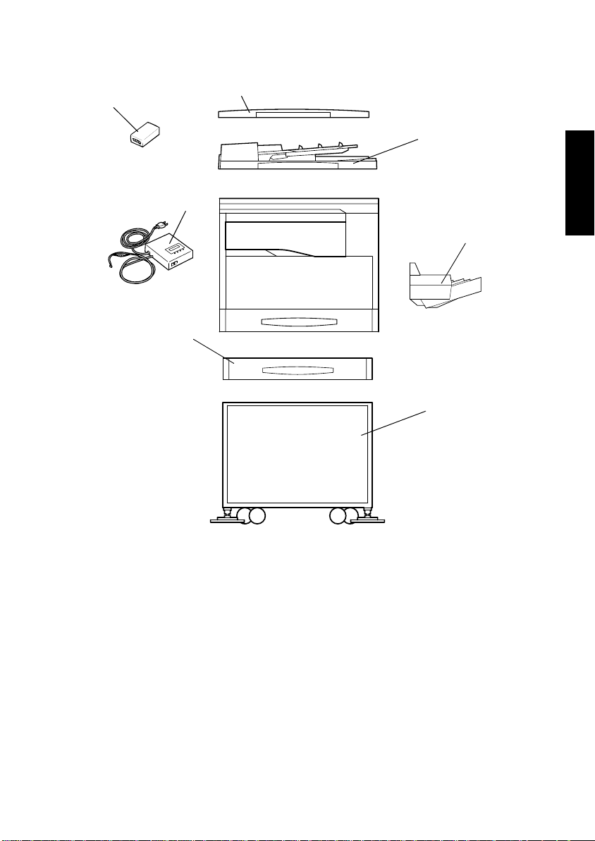
2. COPY PROCESS
4021M065CB
1. PC Drum
• Used as the medium on which a visible developed image of the original is formed.
2. Drum Charging
• A uniform negative DC charge is deposited across the entire surface of the PC Drum.
3. Photoelectric Conversion
• CCD converts the image data represented by light reflected off the original to a corresponding electrical signal which, in turn, is output to IR image-processing section.
4. IR Image-Processing
• The electrical signal is converted to an 8-bit digital image signal (A/D conversion) which,
in turn, goes through appropriate correction before being output to the PH Image Processing.
5. PH Image Processing
• After going through corrections, the digital image signal is converted to a corresponding
electrical signal (D/A conversion) that controls the intensity of the light from the laser
diode.
6. Laser Exposure
• The laser beam strikes the surface of the PC Drum, forming an electrostatic latent image.
7. Developing
• Toner negatively charged in the Developer Mixing Chamber is attracted onto the electrostatic latent image changing it to a visible, developed image.
• An AC/DC negative bias voltage is applied to the Sleeve/Magnet Roller to prevent toner
from being attracted onto those areas of the PC Drum which correspond to the background areas of the original.
8. Paper Feed
• Paper is fed from the drawer.
M-2
Page 19

9. Bypass Paper Feed
• Feeds paper from the Manual Bypass Tray, one piece at a time.
• The optional Multiple Bypass T ray (MB-5), when mounted on the machine, permits continuous paper feeding.
10. Image Transfer
• A DC positive charge is applied to the Image Transfer Roller to transfer the visible image
on the surface of the PC Drum onto the paper.Paper Separation.
11. Paper Separation
• The PC Drum Paper Separator Fingers remove paper from the surfa ce of the PC Drum.
• The Charge Neutralizing Plate neutralizes any charge left on the paper.
12. Cleaning
• Residual toner on the surface of the PC Drum is scraped off.
• The toner is then recycled back to the Developing Unit.
13. Main Erase
• Light is directed to the surface of the PC Drum to neutralize any surface potential remaining there after cleaning.
14. Paper Transport
• The paper is fed to the Fusing Unit.
15.Fusing
• The developed image is permanently fused to the paper by a combination of heat and
pressure applied by the Right and Left Fusing Rollers.
16. Paper Exit
• The paper is fed out onto the Exit Tray.
• When the optional Job Tray (JS-202) is mounted, the specific tray into which paper is f ed
is selected according to the application mode.
• The optional Shifting Unit (OT-103), when mounted, permits different finishing functions
set on the machine (Non-Sort, and Sort) .
M-3
Page 20
3. DRIVE SYSTEM
1
Paper Exit Roller Gear
Transport Roller Gear
Fusing Roller Gear
1. Scanner Motor M5
2. Main Motor M1
PC Drum
Synchronizing Roller Clutch
Paper Take-Up Roller Gear
2
4021M003AA
M-4
Page 21
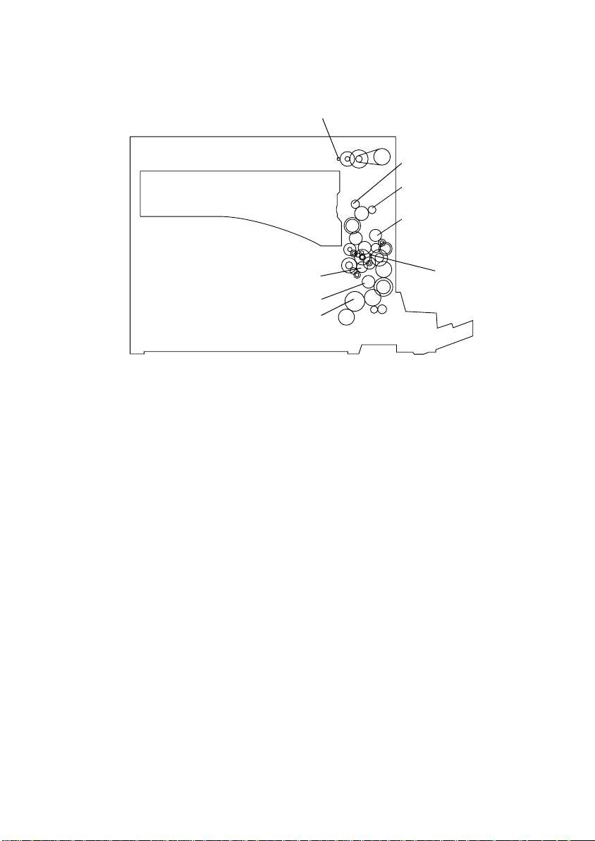
4. SEQUENTIAL EXPLANATION
4021M510CA
Power Switch ON Start Key ON
Polygon Motor M2
Predrive
150 ˚C Warm-up completed
Exposure Lamp LA2
Main Motor M1
Paper Take-Up Solenoid SL1
Synchronizing Roller Sensor PC1
Synchronizing Roller Clutch CL1
Developing Bias (VB) DC
Developing Bias (VB) AC
Image Transfer Bias (+)
Image Transfer Bias (–)
Exit Paper Sensor PC3
M-5
Full speed
Full speed
Speed reduction
Speed reduction
Power Supply Cooling
Fan Motor M4
Fusing Cooling Fan
Motor M3
Page 22

5. WATCHDOG FUNCTION (CPU OVERRUN MONITOR)
• The watchdog function, or CPU overrun monitor function, monitors whether any of the
CPUs mounted in the copier overruns.
• If the function detects that a CPU overruns, the copier automatically resets the CPU,
thereby restarting the logic circuit and mechanism.
5-1. Watchdog Function Post-Processing
The following processing is performed if a faulty condition is detected in the CPU.
When the copier CPU is found faulty:
• All CPUs are reset and the system is restarted.
• If the CPU is found faulty during a copy cycle, the system attempts to feed all sheets of
paper out of the copier before restarting. (If paper is left inside the copier, the copier
detects it as a misfeed as it is restarted.)
M-6
Page 23

6. IMAGE STABILIZATION SYSTEM
The following image stabilization controls are provided to ensure stabilized copy image.
Purpose Means Control
The Vg/Vb control voltage is varied to bring
Vg/Vb to an appropriate level according to
the following settings.
To stabilize image density. Vg/Vb control
To stabilize image transfer.
Image transfer
output control
• Tech. Rep. Choice: ID Adjustment
• Tech. Rep. Choice: VG Adjustment
• User's Choice: Print Density
• IU Life Counter
• Paper type
The image transfer output is varied to bring
the image transfer current to an appropriate
level according to the following conditions.
• Paper type
• Paper width
• B/W ratio of image
M-7
4021M066CA
Page 24

7. IMAGING UNIT (I/U)
• The IU integrates the PC Drum, Developing Unit, PC Drum Charge Corona, and the PC
Drum Cleaning Mechanism, all in one body.
PC Drum
PC Drum Cleaning Mechanism
4021M006AB
PC Drum Charge Corona
Developing Unit
4021M007AB
M-8
Page 25

7-1. Imaging Unit (IU) Drive Mechanism
• The IU is driven by the Main Motor.
Main Motor M1
4021M008AB
Elevtrical Component Control Signal
M1
PWB-A PJ7A-5 L L H
PWB-A PJ7A-7 H L H
Forward
Rotation
M-9
Backward
Rotation
OFF Wiring Diagram
17-G
Page 26

8. PC DRUM SECTION
• The PC Drum consists of layers of semiconductive materials placed on an aluminum
alloy base, on which an electrostatic latent image is formed.
PC Drum
(PC Drum Cross-Section)
Charge Transport Layer
Charge Generation Layer
1167M007AA
8-1. PC Drum Drive Mechanism
• The PC Drum is rotated by drive from a motor.
PC Drum
Aluminum Base
1139M007AA
Main Motor M1
Elevtrical Component Control Signal
M1
PWB-A PJ7A- 5 L H
PWB-A PJ7A- 7 H H
Forward
Rotation
M-10
4021M009AA
OFF Wiring Diagram
17-G
Page 27

8-2. Grounding of the PC Drum
• The potential on the surface of the PC Drum exposed to the light is grounded to the
frame.
PC Drum
Frame
Ground Plate
4021M010AA
M-11
Page 28

9. PC DRUM CHARGING SECTION
• The PC Drum Charge Corona has a scorotron grid to deposit a charge evenly across the
surface of the PC Drum.
• The corona unit has a comb electrode that discharges only toward the grid mesh, thus
minimizing the amount of ozone produced.
Comb Electrobe
Grid Mesh
Elevtrical Component Control Signal ON OFF Wiring Diagram
HV1 PWB-A PJ8A-8 L H 5-C
4021M011AA
M-12
Page 29

10. IMAGE READING SECTION
6
5
1. Scanner /Motor M5
2. CCD Board PWB-J
3. Size Reset Switch S10
1
4. Scanner
5. 2nd/3rd Mirrors Carriage
6. Scanner Home Position Sensor PC6
2
3
4
4021M012AB
M-13
Page 30

10-1. Image Processing Process
1. Photoelectric Conversion
• Light reflected off the original is read by the CCD Sensor which converts the data to a
corresponding analog signal.
2. Analog-to-Digital Conversion
• The analog signal output from the CCD Sensor is converted to a corresponding 8-bit digital signal.
3. Shading Correction
• An error is corrected that occurs due to variations in sensitivity of each CCD chip and the
light distribution varying along the length of the Exposure Lamp.
• The data obtained through actually illuminating the shading sheet with the Exposure
Lamp is compared with the shading sheet reading reference value (white = max. data
value) to make the necessary correction.
4. Zoom Processing
• The synchronous timing of the input data (read) and output data (read) is varied to
decrease (reduction) or increase (enlargement) the number of data readings, thereby
reducing or enlarging the image in the main scanning direction.
5. Data is sent to the PH.
M-14
Page 31

10-2. Exposure Components Section
1
2
4021M013AA
3
1. Auxiliary Reflector
When a book or other bound original is copied, the paper in the area near the binding
generally fails to come flush against the glass, so that the copy of these areas is generally too dark. The Auxiliary Reflector reduces this problem by reflecting light from the
Exposure Lamp onto these areas of the original.
2. Exposure Lamp LA2
A fluorescent lamp is used to illuminate the original.
3. 1st Mirror
Directs the light reflected off the original to the 2nd Mirror.
M-15
Page 32

10-3. Scanner and Mirrors Carriage Movement Mechanism
(1) Scanner Movement Mechanism
• The Scanner is driven by the Scanner Motor.
(2) 2nd/3rd Mirrors Carriage Movement Mechanism
• The 2nd/3rd Mirrors Carriage moves at a speed half that of the Scanner, thereby keeping
constant the optical path length between the original and the CCD Board.
Scanner Motor M5
2nd/3rd Mirrors Carriage
CCD Board PWB-J
Scanner
4021M014AB
M-16
Page 33

10-4. Scanner Motor Drive Control
• The speed at which the Scanner is moved is controlled by varying the period of the motor
drive pulse that is timed with the reference clock.
High Speed
Low Speed
Period
• The distance over which the Scanner travels is controlled by the number of motor drive
pulses that correspond to each paper size and zoom ratio.
Elevtrical Component Control Signal ON OFF Wiring Diagram
M5 PWB-C JP5C-1 to 4 Pulse output 11-B
M-17
Page 34

11. MEMORY STORAGE IMAGE PROCESSING SYSTEM
• Based on the image data output from the IR, a laser light is projected onto the surface of
the PC Drum to form a corresponding latent image.
PH Unit
4021M015AA
M-18
Page 35

11-1. Laser Exposure Process
1. The Start key is pressed.
2. The laser diode is forced to turn ON and the laser intensity is automatically adjusted.
3. The SOS Sensor Board is illuminated by the laser beam, which generates an SOS sig-
nal.
4. The SOS signal determines the laser emission timing for each main scanning line.
5. The surface of the PC Drum is illuminated by the laser beam corresponding to the
image data, which forms an electrostatic latent image.
Polygon Motor M2
LD Board PWB-B
SOS Mirror
PC Drum
SOS Board
PC Drum
SOS Mirror
DCBA
SOS
Sensor
4021M016AA
SOS Signal
1171M038AA
A to B: LD activation
B to C: LD OFF
C to D: Laser beam exposure area according to the image data
Elevtrical Component Control Signal ON OFF Wiring Diagram
M2 PWB-A PJ13A-3 L H 8-D
M-19
Page 36

12. DEVELOPING UNIT SECTION
The Developing Unit agitates and triboelectrically charges toner so that it sticks to the electrostatic latent image formed on the surface of the PC Drum, then changing the image to a
visible, developed one.
1
14
13
1. Spent Toner Recycling Coil
2. PC Drum Charge Corona
3. Spent Toner Conveying Screw 2
4. Cleaning Blade
5. Spent Toner Conveying Screw 1
6. PC Drum Paper Separator Finger
7. PC Drum Protective Shutter
12
3
2
11
10
8. PC Drum
9. Sleeve/Magnet Roller
10. 1st Toner Conveying Roller
11. ATDC Sensor UN1
12. 2nd Toner Conveying Roller
13. 3rd Toner Conveying Roller
14. Spent Toner Recycling Duct
4
5
6
7
8
4021M017AA
9
M-20
Page 37

12-1. Developing Unit Drive Mechanism
The rollers are driven through a gear train from the motor.
Sleeve/Magnet Roller
Main Motor M1
1st Toner Conveying Roller
2nd Toner Conveying Roller
4021M008AB
Elevtrical Component Control Signal
M1
PWB-A PJ7A-5 L H
PWB-A PJ7A-7 H H
Forward
Rotation
3rd Toner Conveying Roller
OFF Wiring Diagram
17-G
M-21
Page 38

12-2. Sleeve/Magnet Roller
• The Sleeve/Magnet Roller, which consists of an outer sleeve roller and an inner magnet
roller, conveys developer to the point of development.
• The magnetic force of the magnet roller at the point of development is the strongest so
that the developer brush stands straight up to deliver the greatest amount of toner to the
point of development.
Sleeve/Magnet Roller
PC Drum
Sleeve/Magnet Roller
1171M027AA
4021M062AA
1st Toner Conveying Roller
12-3. Developing Bias
• Vb (-DC, AC) is applied to the Sleeve/Magnet Roller.
• Vb (-DC) is applied to prevent toner from sticking to the background of the image.
• Vb (AC) is applied to enhance good separation of toner from carrier.
• The amount of toner sticking to the surface of the PC Drum is varied according to the difference in potential between the voltage (Vi) on the surface of the PC Drum and
Vb (-DC).
✽
Large difference = A greater amount of toner sticks.
✽
Small difference = A smaller amount of toner sticks.
PC Drum
Sleeve/Magnet Roller
Elevtrical Component Control Signal ON OFF Wiring Diagram
Vb (-DC) PWB-A PJ8A-9 L H
Vb (AC) PWB-A PJ8A-10 L H
Developing Bias Terminal
4021M018AB
6-B
M-22
Page 39

12-4. ATDC Sensor
The ATDC Sensor detects the toner-to-carrier ratio (T/C) of the developer in the Developer
Mixing Chamber.
2nd Toner Conveying Roller
ATDC Sensor UN1
4021M019AA
(1) ATDC Sensor Automatic Adjustment
The reference value for the ATDC Sensor is automatically adjusted as detailed below using
the ATDC Sensor Automatic Adjustment mode.
With the copier set in the ATDC Sensor Automatic Adjustment mode, press the Start key.
The developer is mixed.
The ATDC Sensor converts the reference T/C (14 %) to a corresponding voltage
value and outputs it.
Does the output voltage fall within the range from 2.36 to 2.44 V?
YES NO
The voltage input to the ATDC Sensor from the
Master Board at this time is fixed as the reference
voltage.
The voltage input to the ATDC Sensor from
the Master Board is varied.
2.45 V or more: Decrease the voltage.
2.35 V or less: Increase the voltage.
M-23
Page 40

12-5. Toner Replenishing Mechanism
• Toner is supplied from the Toner Bott le to the Developer Mixing Chamber.
1. The coupling is turned by the motor, which turns the Toner Bottle.
2. To regulate the amount of toner supplied from the Toner Bottle, there is a Metering
Chamber provided in the outer race of the coupling.
3. When the Toner Bottle turns, toner in the Metering Chamber drops.
4. Toner from the metering chamber is conveyed by the Toner Conveying Screw into the
Developer Mixing Chamber.
5. The Toner Conveying Screw is turned by the motor.
coupling
4021M022AA
Toner Bottle
Metering
Chamber
4021M020AB 4021M021AB
Toner Conveying Screw
Developer Mixing Chamber
Elevtrical Component Control Signal ON OFF Wiring Diagram
M6 PWB-A PJ19A-6 L H 4-B
4021M023AA
M-24
Page 41

12-6. Toner Replenishing Control
• Replenishing of the supply of toner is determined based on the T/C ratio and B/W ratio.
• If T/C is 14 % or more, toner replenishing is not carried out regardless of the B/W value.
• If T/C is less than 14 %, toner replenishing is determined according to the B/W value.
• Toner is replenished until T/C becomes 14 %.
T/C ratio (%) B/W ratio toner replenishing
More than 14 — not supply
13.5 to 14 More than 2000 supply
13 to 13.5 More than 1000 supply
12.5 to 13 More than 500 supply
12 to 12.5 More than 500 supply
10 to 12 More than 0 supply
Less than 7 Proceeds to the T/C recovery mode
✽
The greater the value of B/W in the table, the higher the B/W ratio (high image density
original).
M-25
Page 42

12-7. T/C Recovery Mode
The machine enters the T/C recover mode when a T/C of 10 % or less is detected.
Toner is replenished for 90 sec.
T/C is recovered by 1 % or more. T/C is not recovered by 1 % or more, or T/C
Toner is replenished for 60 sec.
T/C is recovered by 2 % or more, or is 12 % or more. T/C is not recovered by 2 % or
Toner is replenished for 30 sec. to complete the A toner-empty condition is detected.
T/C recovery mode.
A toner-empty-stop condition results and the initiation
of any new copy cycle is prohibited.
✽
A toner-empty condition is reset when the Front Cover is opened and closed after a T/C
of 10 % or more is detected with the supply of toner replenished.
✽
A toner-empty-stop condition is reset when the Front Cover is opened and closed after a
T/C of 8 % or more is detected with the supply of toner replenished. A toner-empty condition results, howev er, if T/C falls within the range between 8 % and 10 % when the Front
Cover is opened and closed.
is less than 12 %.
more, or T/C is less than 12 %.
T/C is less than 8 %.
M-26
Page 43

12-8. Toner Bottle Home Position Detection Mechanism
• The Toner Bottle is at its home position (where it remains stationary) when its Toner Supply Port faces up. This position is detected by a sensor.
Toner Bottle Home Position Sensor PC7
Toner Supply Port
4021M024AA
Elevtrical Component Control Signal Activated Deactivated Wiring Diagram
PC7 PWB-A PJ19A-10 L H 4-B
M-27
Page 44

13. PAPER TAKE UP/FEED SECTION
1
2
1. Paper Size Detecting Board PWB-I
2. Paper Size Detecting Sensor S11
3. Paper Empty Sensor PC4
3
4
5
6
4021M025AA
4. Paper Take-Up Roll
5. Separator Roll
6. Paper Lifting Plate
M-28
Page 45

13-1. Drawer In Position Detection
• When the drawer is slid into the copier, the light blocking plate blocks the Set Sensor.
The copier then knows that the drawer has been slid in position.
Drawer Set Sensor PC5
Elevtrical Component Control Signal Activated Deactivated Wiring Diagram
PC5 PWB-A PJ15A-10 L H 1-I
4021M026AA
13-2. Paper Empty Detection Mechanism
• The Paper Empty Sensor detects a paper-empty condition in the drawer.
Paper Empty Sensor PC4
1167M073AD
Elevtrical Component Control Signal Activated Deactivated Wiring Diagram
PC4 PWB -A PJ6A-6 L H 1-I
M-29
Page 46

13-3. Paper Lifting Plate
• The Paper Lifting Plate is locked into position when it is pressed down. It is unlocked
when the tray is slid into the unit.
• The Paper Lifting Plate is pushed upward by the Paper Lifting Springs at all times.
Paper Lifting Plate
Spring
4021M063AA
13-4. Universal Tray Paper Size Detection Mechanism
• Both the width (in the crosswise direction) and length (in the feeding direction) of the
paper are detected and the copier CPU determines the paper size based on the combination of the two readings.
• The width (CD) of the paper is detected when the lever that is operatively connected to
the Edge Guide activates or deactivates the Paper Size (CD) Detection Sensor.
• The length (FD) of the paper is detected when the lever that is operatively connected to
the Trailing Edge Stop actuates or deactuates the switches on the Paper Size (FD)
Detection Board.
Paper Size Detecting Board PWB-I
Paper Size Detecting Sensor S11
12 34
4011M009AA
M-30
Page 47

Paper Size Detecting Board
PWB-I
SW1 SW2 SW3 SW4
— — — — — B4L, 8-1/2 × 14
— — — — Activated 11 × 14
— — — ON Activated A3L, 11 × 17
— — ON ON — A5L, 5-1/2 × 8-1/2 L
— — ON ON Activated A4C, 8-1/2 × 11 C
— ON — — — A5C, 5-1/2 × 8-1/2 C
— O N ON ON — A5L, 5-1/2 × 8-1/2 L
— ON ON ON Activated A4C, 8-1/2 × 11 C
ON — — — — FLS
ON ON — — — FLS
ON ON ON ON — A4L, 8-1/2 × 11 L
Elevtrical Component Control Signal ON OFF Wiring Diagram
PWB-I SW1 PWB- A PJ15A-1 L H
PWB-I SW2 PWB- A PJ15A-2 L H
PWB-I SW3 PWB- A PJ15A-3 L H
PWB-I SW4 PWB- A PJ15A-4 L H
Elevtrical Component Control Signal Activated Deactivated Wiring Diagram
S11 PWB-A PJ15A-7 H L 1-H
Paper Size Detecting
Sensor S11
Paper Size
2-H
M-31
Page 48

13-5. Paper Take Up Mechanism
• Drive for the paper take-up sequence is transmitted via t he P aper Take-Up Solenoid from
a motor.
Main Motor M1
Paper Take-Up Roll
Paper Take-Up Solenoid SL1
(1) Paper Separating Mechanism
• The coefficient of friction between the Paper Take-Up Roll and Separator Roll is effectively used to prevent double feed of paper.
When one sheet of paper is taken up:The coefficient of friction on the front side of the
When two or more sheets of paper are taken up:The coefficient of friction between the
Paper Take-Up Roll
sheet of paper taken up and fed through the space
between the Paper Take-Up Roll and Separator Roll
is the same as that on the backside of the sheet of
paper, allowing the paper to be properly fed into the
machine.
paper and the Separator Roll is greater
than that between the sheets of paper,
which allows only the top sheet of paper to
be fed into the machine.
Paper
Separator Roll
4021M060AB
4021M027AA
M-32
Page 49

13-6. Paper Take Up Control
Start Key ON
Main Motor M1
Paper Take-Up
Solenoid SL1
Synchronizing Roller
Sensor PC1
Elevtrical Component Control Signal
M1
Elevtrical Component Control Signal ON OFF Wiring Diagram
SL1 PWB-A PJ5A-2 L H 1-I
Elevtrical Component Control Signal Activated Deactivated Wiring Diagram
PC1 PWB -A PJ6A-3 L H 1-F
(1) Paper Take Up Retry Control
• To minimize the occurrence of a paper misfeed, the paper take-up sequence is temporarily halted if the paper fails to reach the Synchronizing Roller Sensor within a given
period of time after the sequence has been started. The paper take-up sequence is then
performed again. These paper take-up sequences are repeated a given number of times.
ON
OFF
ON
OFF
H
L
Forward
Rotation
PWB-A PJ7A-5 L H
PWB-A PJ7A-7 H H
4021M515CA
OFF Wiring Diagram
17-G
Paper Take-Up Retry 2
Paper Take-Up
Solenoid SL1
Synchronizing Roller
Sensor PC1
ON
OFF
H
L
M-33
No. of Paper Take-Up
Retry Sequences
1st Paper Take-Up
Retry Sequence
Successful paper take-up
4021M514CA
Page 50

14. MANUAL BYPASS SECTION
14-1. Paper Take Up Drive Mechanism
• Drive for paper take-up from the Manual Bypass is transmitted from a motor via the Solenoid.
Main Motor M1
Manual Feed Paper Sensor PC2
Manual Bypass Solenoid SL2
4021M028AA
14-2. Paper Detection Mechanism
• The Sensor detects a sheet of paper on the Manual Bypass.
<When Paper is not Present><When Paper is Present>
Manual Feed Paper Sensor PC2
Paper
M-34
4021M029AA4021M061AA
Page 51

14-3. Manual Feed Take Up Control
Paper Set
Manual Feed
Paper Sensor PC2
Main Motor M1
Manual Bypass
Solenoid SL2
Elevtrical Component Control Signal
M1
Elevtrical Component Control Signal ON OFF Wiring Diagram
SL2 PWB-A PJ4A-2 L H 1-B
Elevtrical Component Control Signal Activated Deactivated Wiring Diagram
PC2 PWB -A PJ4A-5 L H 1-A
H
L
ON
OFF
ON
OFF
Paper drawing-in sequence completed
PWB-A PJ7A-5 L H
PWB-A PJ7A-7 H H
Start Key ON
Forward
Rotation
4021M511CA
OFF Wiring Diagram
17-G
M-35
Page 52

15. MULTIPLE BYPASS SECTION
1
2
4021M031AA
1. Paper Take-Up Roll
2. Multiple Bypass Solenoid SL21
3
3. Multiple Bypass Paper Empty Sensor
PC21
15-1. Paper Take Up Drive Mechanism
• Drive for paper take-up from the Multiple Bypass is transmitted from a motor via the Solenoid.
Main Motor M1
Multiple Bypass Solenoid SL21
Paper Take-Up Roll
4021M032AA
Multiple Bypass Paper Empty Sensor PC21
M-36
Page 53

15-2. Paper Take-Up Mechanism
• The Paper Lifting Plate is raised to press the paper stack on the tray up against the
Paper Take-Up Roll.
• The Paper Lifting Plate is raised and lowered in time with a paper take-up sequence.
• The ascent and descent motion of the P aper Li fting Plate is accomplished when the drive
from the motor is transmitted to the cam through a solenoid to rotate the cam.
Drive from Main Motor
Paper Take-Up Roll
Cam
<Ascent/Descent Motion>
Main Motor (M1) is energized.
Paper Take-Up Roll is turned.
Multiple Bypass Solenoid (SL21): Energized
Cam: Rotates
Tray: Raised
Multiple Bypass Solenoid (SL21): Deenergized
Multiple Bypass Solenoid SL21
4021M033AA
Paper Take-Up Roll
Cam
Paper
Tray
Paper take-up
Multiple Bypass Solenoid (SL21): Energized
Cam: Rotates
Tray: Lower ed
Multiple Bypass Solenoid (SL21): Deenergized
M-37
4021M059AA
Page 54

15-3. Paper Empty Detection Mechanism
• The Paper Empty Sensor detects a sheet of paper on the Multiple Bypass.
<When Paper is not Present><When Paper is Present>
Multiple Bypass Paper Empty Sensor PC21
Paper
4021M034AA
4021M035AA
15-4. Paper Take Up Control
Paper Set Start Key ON
ON
OFF
ON
OFF
H
L
4021M512CA
Forward
Rotation
OFF Wiring Diagram
17-G
Multiple Bypass Paper
Empty Sensor PC21
Main Motor M1
Multiple Bypass Solenoid
SL21
Elevtrical Component Control Signal
M1
Elevtrical Component Control Signal ON OFF Wiring Diagram
SL21 PWB-A PJ4A-2 L H 17-F
Elevtrical Component Control Signal Activated Deactivated Wiring Diagram
PC21 PWB-A PJ4A-5 L H 17-F
PWB-A PJ7A-5 L H
PWB-A PJ7A-7 H H
M-38
Page 55

15-5. Paper Take Up Retry Control
• To minimize the occurrence of a paper misfeed, the paper take-up sequence is temporarily halted if the paper fails to reach the Synchronizing Roller Sensor within a given
period of time after the sequence has been started. The paper take-up sequence is then
performed again. These paper take-up sequences are repeated a given number of times.
No. of Paper Take-Up
Retry Sequences
Paper Take-Up Retry 2
1st Paper Take-Up
Retry Sequence
Multiple Bypass
Solenoid SL21
Synchronizing
Roller Sensor PC1
ON
OFF
H
L
Successful paper take-up
4021M516CA
M-39
Page 56

16. IMAGE TRANSFER AND PAPER SEPARATION SEC-
TION
✽
Image Transfer
• A positive charge is applied to the Image Transfer Roller to transfer the toner image
formed on the surface of the PC Drum onto the paper.
• The charge applied to the Image Transfer Roller is varied according to the following conditions to ensure that image transfer efficiency is stabilized.
Paper Type: The amount of charge is made less for OHP transparencies.
Paper width: The greater the paper width, the more the amount of charge.
B/W ratio of the image: The higher the B/W ratio, the more the amount of charge.
• A negative charge is applied to the Image Transfer Roller to return toner sticking to the
Image Transfer Roller to the PC Drum. It is performed in the following timings:
• A copy cycle is started and completed, The Power Switch is turned ON, A misfeed or a
malfunction is reset.
✽
Paper Separation
• The PC Drum Paper Separator Fingers mechanically separate paper from the surface of
the PC Drum to ensure good and positive paper separation.
• The Charge Neutralizing Plate is used to neutralize any charge left on the paper , to which
image has been transferred, thereby preventing discharge noise that occurs when paper
is separated.
PC Drum Paper Separator Fingers
PC Drum
Charge Neutralizing Plate
4021M037AA
Image Transfer Roller
Elevtrical Component Control Signal ON OFF Wiring Diagram
HV1 PWB-A PJ8A-8 L H 6-C
M-40
Page 57

17. PC DRUM CLEANING SECTION
• The Cleaning Blade is used to scrape residual toner off the surface of the PC Drum.
• The spent toner is conveyed through the Recycling Duct and eventually back to the
Developer Mixing Chamber.
• To prevent paper dust from being compacted on the edge of the Cleaning Blade, the PC
Drum is turned backward (by turning the Main Motor backward) when the cumulative
time through which the PC Drum has turned reaches a predetermined value. When the
PC Drum is turned backward, a backlash in gears prevents drive from being transmitted
to other drive mechanisms.
Cumulative Time Through Which PC Drum
Has Been Driven
Approx. 330 sec 50 ms
PC Drum
4021M039AA
Spent Toner Recycling Coil
Spent Toner Recycling Duct
Cleaning Blade
PC Drum Backward
Rotation Time
Spent Toner Conveying Screw 1
Spent Toner Conveying Screw 2
M-41
4021M038AB
Page 58

18. MAIN ERASE SECTION
• Any potential remaining on the surface of the PC Drum is neutralized by both light from
the Main Erase and a negative voltage applied by the Charge Neutralizing Sheet.
• A negative charge is applied to the Charge Neutralizing Sheet to neutralize a positive
charge on the surface of the PC Drum. The Main Erase then illuminates the surface of
the PC Drum to neutralize the charge left on it.
Main Erase LA1
Charge Neutralizing Sheet
PC Drum
4021M040AA
Elevtrical Component Control Signal ON OFF Wiring Diagram
LA1 PWB-A PJ7A-12 L H 4-A
M-42
Page 59

19. FUSING UNIT SECTION
• The Fusing Unit fixes permanently the developed image to the paper by applying heat
and pressure to the toner and paper.
1
10
9
8
1. Paper Exit Roller
2. Transport Roller
3. Fusing Paper Separator Finger
4. Exit Paper Sensor PC3
5. Right Fusing Roller
2
3
7
6. Pressure Spring
7. Fusing Heater Lamp H1
8. Thermistor TH1
9. Thermoswitch TS1
10. Left Fusing Roller
4
5
4021M041AD
6
M-43
Page 60

19-1. Fusing Unit Drive Mechanism
• The Fusing Unit is driven by a motor.
Left Fusing Roller
Main Motor M1
Right Fusing Roller
4021M042AA
19-2. Fusing Rollers Pressure Mechanism
• To ensure that there is a certain width of area of contact between the Right and Left Fusing Rollers, a pressure spring is used to press the Lower Fusing Roller up against the
Upper Fusing Roller.
Right Fusing Roller
Left Fusing Roller
4021M043AA
Pressure Spring
M-44
Page 61

19-3. Fusing Temperature Control
• The Fusing Roller Heater Lamp is turned ON and OFF to keep a set temperature on the
surface of the Fusing Roller.
• The Fusing Roller surface temperature is detected by using a thermistor that translates
the temperature to a corresponding electrical signal.
• If the Fusing Roller temperature becomes excessively high, the Fusing Roller Heater
Lamp is shut down.
<Temperature Control in Standby State>
(˚C)
200
190
180
Warm-up completed
170
155
30 sec.
or less
Mode 1
5 min
Mode 2
1 min
Mode 3
4021M513CA
Machine Condition or Paper Type Mode 1 Mode 2 Mode 3
Standby 180 °C 180 °C → 170 °C 170 °C
Plain paper (width 251 mm or more) 190 °C 190 °C → 170 °C 170 °C
Plain paper (width 250 mm or less) 160 °C 160 °C 160 °C
Thick paper (width 251 mm or more) 210 °C 210 °C → 190 °C 190 °C
Thick paper (width 250 mm or less) 200 °C 200 °C → 190 °C 190 °C
OHP transparencies (width 251 mm or more) 180 °C 180 °C → 165 °C 165 °C
OHP transparencies (width 250 mm or less) 155 °C 155 °C 155 °C
Elevtrical Component Control Signal ON OFF Wiring Diagram
H1 PWB-A PJ10A-7 L H 1-D
19-4. CPM Control
• If paper of a small size (width of 250 mm or less) or thick paper is used to run a multicopy cycle, the temperature on the edges of the Fusing Rollers tends to run high, meaning that the temperature of the Fusing Rollers varies among different spots of the rollers.
• When the cumulative number of copies made through continuous copy cycles* exceeds
30, the paper take-up interval is made longer, thereby allowing the temperatures of the
Fusing Rollers at different spots to be uniform.
✽
Continuous copy cycle: Continuous copy cycles run with an interval of 2 min. or less
between cycles.
M-45
Page 62

20. JOB TRAY (JS-202): Option
1
1. Job Tray
2. Main Board PWB-A
3. Paper Empty Sensor PC35
4. Full Detecting Sensor PC34
2
5. Upper Home Position Sensor PC32
6. Lower Home Position Sensor PC33
7. Paper Detecting Board PWB-B
8. Bin Switching Motor M1
3
4
6
5
4021M045AC
7
8
M-46
Page 63

20-1. Tray Selecting Mechanism
• Paper is fed into either the Exit Tray of the machine or the Job Tray. Either is selected
according to the application mode (fax, copier, or printer).
• The specific tray in which paper is fed is selected by a motor and a sensor.
<When feeding paper into the Exit Tray: Copier>
Upper Home Sensor PC32: Activated
Paper
(M1: Backward Rotation)
<When feeding paper into the Job Tray: fax/printer>
Lower Home Sensor PC33: Activated
Paper
Bin Switching Motor M1
4021M046AB
Job Tray
4021M047AB
Elevtrical Component Control Signal O N OFF Wiring Diagram
M1 PWB-A PJ2A-1 to 4 Pulse output 16-A
Elevtrical Component Control Signal Activated Deactivated Wiring Diagram
PC32 PWB-A PJ4A-3 L H
PC33 PWB-A PJ4A-6 L H
16-B
M-47
Page 64

20-2. Tray-Full Detecting Mechanism
• Tray-full detection is valid only when paper is fed into the Job Tray (Job Tray in the lowered position).
• A tray-full condition is detected when the sensor is block ed for a continuous given period
of time (approx. 20 sec.).
Paper
Full Detecting Sensor PC34
Exit Roller
Job Tray
4021M049AA
Elevtrical Component Control Signal Activated Deactivated Wiring Diagram
PC34 PWB-A PJ4A-9 L H 16-C
20-3. Job Tray Paper Detecting Mechanism
• If paper is fed into the Job Tray when the machine is in a mode in which paper is fed into
the Exit Tray (Job Tray in the raise position), the indicator lamp on the Paper Detecting
Board lights to warn the user that there is paper in the Job Tray.
• A sensor is provided for detecting paper in the Job Tray.
<When Paper is Present>
Paper Empty Sensor PC35
Paper Detecting
Job Tray
Paper
<When Paper is not Present>
4021M051AA
Board PWB-B
4021M050AA
4021M052AA
Elevtrical Component Control Signal Activated Deactivated Wiring Diagram
PC35 PWB-A PJ3A-3 L H 18-A
M-48
Page 65

21. SHIFTING UNIT (OT-103): Option
1
2
3
4021M053AB
1. Main Board PWB-A
2. Home Sensor S31
3. Shift Motor M1
M-49
Page 66

21-1. Exit Position Shifting Mechanism
• Paper is fed into the Shifting Unit along a straight path or shifted from the reference
straight path position. This exit position shifting mechanism allows different finishing
functions offered by the machine (Non-Sort, Sort, and Group) to be effected.
<Straight Feeding>
• The paper that travels along a straight path is fed straight into the Shifting Unit without
being shifted sideways as the Exit Roller turns.
Exit Roller
Paper
4021M054AA
<Shifted Feeding>
• When the trailing edge of the paper transported to the exit section moves past the Fusing
Roller, the Shift Motor is energized to move the Transport Roller sideways.
• The paper is fed into the Shifting Unit as it is shifted sideways.
• The Exit Roller is moved sideways by turning the motor forward or backward.
• The Exit Roller is detected at its home position by a sensor.
Shift Moto r M1
Paper
4021M055AA
Home Sensor S31
Exit Roller
4021M056AB
M-50
Page 67

Elevtrical
Component
M1 PWB-A PJ2A-1 to 4 Pulse output 16-C
Elevtrical Component Control Signal Activated Deactivated Wiring Diagram
S31 PWB-A PJ3A-3 L H 17-D
Control Signal
Forward
Rotation
Backward
Rotation
OFF Wiring Diagram
M-51
Page 68

22. OTHER MECHANISM
22-1. Cooling Mechanism
(1) Power Supply Section Cooling Mechanism
• A cooling fan motor draws air from the area around the Power Supply Unit to the outside
to prevent the Power Supply Unit temperature from running high.
• The cooling fan motor is turned at full speed when the Main Motor turns and at a speed
reduction during other timings, thereby making the machine quieter without sacrificing
cooling performance.
4021M057AA
Power Supply Cooling F an Motor M4
Elevtrical Component Control Signal ON OFF Wiring Diagram
M4 PWB-A PJ19A-1
analog voltage
output
H 11-I
M-52
Page 69

(2) Fusing Sect ion Cooling Mechanism
• A fan motor draws air from the area around the Fusing Unit to the outside to prevent the
machine interior temperature from running high. In addition, the fan motor pulls paper
being transported up through suction force to help stabilize paper transport.
• Ozone produced from the PC Drum Charge Corona is absorbed by the Ozone Filt er from
the air drawn by a fan motor to the outside.
• The fan motor is turned at full speed during a print cycle and at a speed reduction during
other timings, thereby making the machine quieter without sacrificing cooling performance.
Fusing Cooling Fan Motor M3
Ozone Filter
4021M058AB
Elevtrical Component Control Signal ON OFF Wiring Diagram
M3 PWB-A PJ10A-4
analog voltage
output
H1-C
M-53
Page 70

Service Manual [General]
Di152/Di183
Service Manual
[General]
Di152/Di183
2001 MINOLTA CO., LTD.
Copyright
Printed in Japan
Use of this manual should be strictly supervised to
avoid disclosure of confidential information.
MINOLTA Co.,Ltd.
4021-7990-11 01100500
 Loading...