

Page 1
Adjustment Item List.fm Page 1 Wednesday, September 12, 2001 10:53 PM
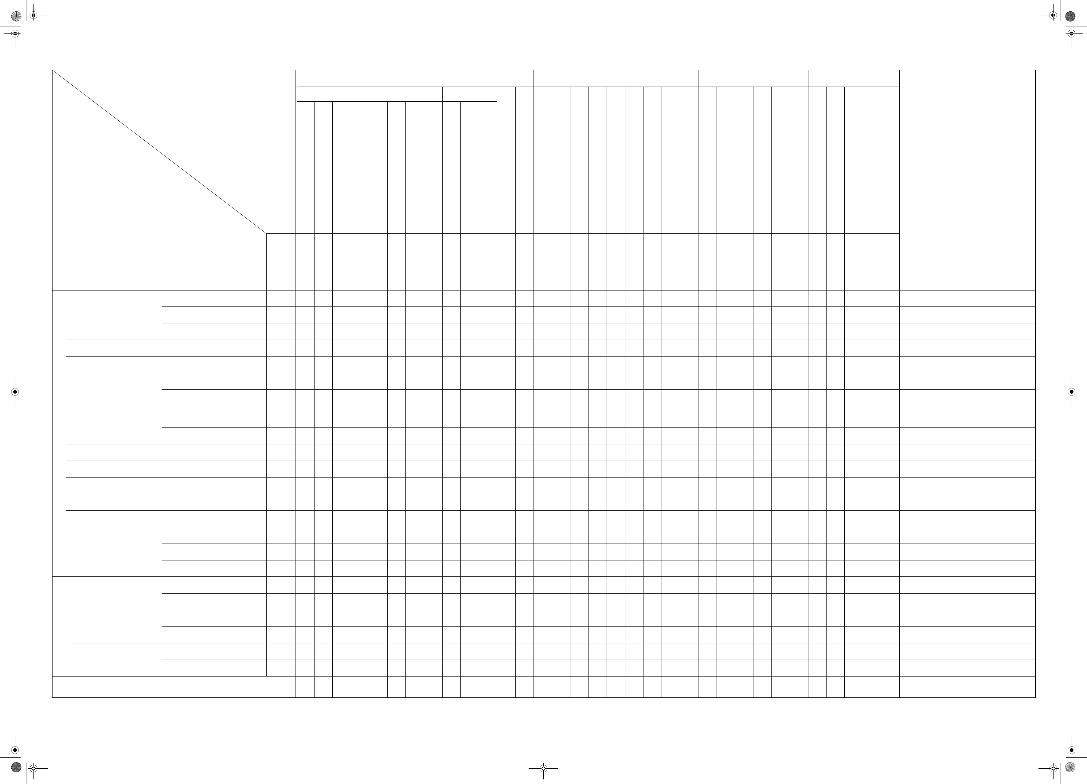
Service/Adjustment Item List
Adjustment/Setting Items
Tech.Rep.Mode Adjust Mode Mechanical Others
Function Tech.Rep.Choice Counter
Note
Service Items
Check
Items
Paper Take-Up Roll (1st Tray) Replace
Paper Take-Up/Transport Section
Optical Section Scanner Rail/Bushing Clean
Paper Separator Roll Assy (1st Tray) Replace
Paper Dust Remover Assy Replace
PC Drum Replace
ADF Document Passage Test
Paper Passage Test
ATDC Se nsor Automatic Adjustment
Test Pattern Output
ID Adjustment
VG Adjustment
Loop Length Adjustment (1st Tray)
Loop Length Adjustment (2nd- 5th Tray)
Loop Length Adjustment (Bypass Tray)
PM Counter
Maintenance Counter
IU Life Counter
|
||||||
Automatic Adjustment
Clear Counter
Clear Counter
||
Clear Counter
Scanner Drive Chec k
23*1
23*1
1*
31 2
Printer CD Registration Adjustment
20±2.0 mm
Printer FD Registration Adjustment
20±1.5 mm
Scanner CD Zoom Adjustment
Scanner FD Zoom Adjustment
Scanner CD Registratio n Adjustm ent
Scanner FD Registration Adjustment
ADF FD Zoom Adjustment
ADF CD Registration Adjustment
ADF FD Registration Adjustment
Application of toner to PC Drum
Focus-Positioning of Scanner and 2nd/3rd Mirrors Carriage
Scanner Motor timing belt tension adjustment
CCD Unit position adjustment
Multiple Bypass position adjustment
Manual Bypass registration adjustment
Re-setting of various functions
Remount EEP ROM (U29)
Adjust Label
Change of developer
Application of lubricant
|
20±2.0 mm
200±2.0 mm
300±3.0 mm
20±1.5 mm
20±2.0 mm
300±4.5 mm
20±2.5 mm
|
Jig
Jig
Re-input
200±2.0 mm
0±2.0 mm
Remount
||
write down the data
* Check when setting is changed.
* Check when setting is changed.
* When maintenance counter is set.
1
Cleaning Blade R epl ac e
Imaging Unit Section
PM
Image Transfer Section Image Transfer Roller Assy Replace
Fusing Section Fusing Unit Replace
Multiple Bypass (Option)
Paper Feed cabinet (Option) Paper Take-Up Roller Replace
Automatic Document Feeder (Option)
PC Drum Charge Corona Assy Replace
Developer Replace
Ozone Filter Replace
Paper Take-Up Roll Replace
Paper Separator Roll Assy Replace
Pick-Up Roller Replace
Paper Take-Up Roller Replace
12
32* 1
2*,4 3* 1 4
1
1
1
45*1 23
23*1
23*1
12
12
* Check when setting is changed.
2* Run F8 twice before removing the PC Drum Unit.
3* Check when setting is changed.
* Check when setting is changed.
* Check when setting is changed.
* Check when setting is changed.
Electrical Parts
Units
Others
Parts other than PM Parts
Paper Separator Roller Replace
ATDC Sensor Replace
Control Board (PWB-C) Replace
PH Unit Replace
CCD Unit Replace
Memory Clear
Scanner Drive Cable Install
Ref.Page S-13
1*,3 42
D-30
S-13 S-13 S-13 D-54 D-54 D-54 S-13 S-13 S-13 S-1* S-13 D-55 D-56 D-59 D-60 D-57 D-58 D-8* D-9* D-10* D-34 D-64 D-51 D-65 D-42 D-63
D-61
12
123456789
23 4 1
345 21
NOTES: Before executing a Memory Clear, be sure to take notes of the settings and adjustment data of Utility, Tech. Rep., Security, and Adjust modes. Aft er the Memory Clear has been executed, re-enter those data.
: The following data of Adjust mode are indicated at the factor y on the Adjust Label located inside the Front Door: Printer CD Registration (1st Tray), Printer FD Registration, Scanner CD Zoom, Scanner FD Zoom, Scanner CD Registration, and Scanner FD Registration.
: The ATDC value at the time of setting up of the PC Drum Unit is also entered on the Adjust Label at installation.
* Run F8 twice before removing the PC Drum Unit.
1
1
|
D-70
|
D-30 D-22 * Ref. page of AF-10 Service Manual.
4021-7993-11
Page 2
Page 3
Page 4

Electrical.fm Page 1 Wednesday, September 12, 2001 10:46 PM
123456789101112131415
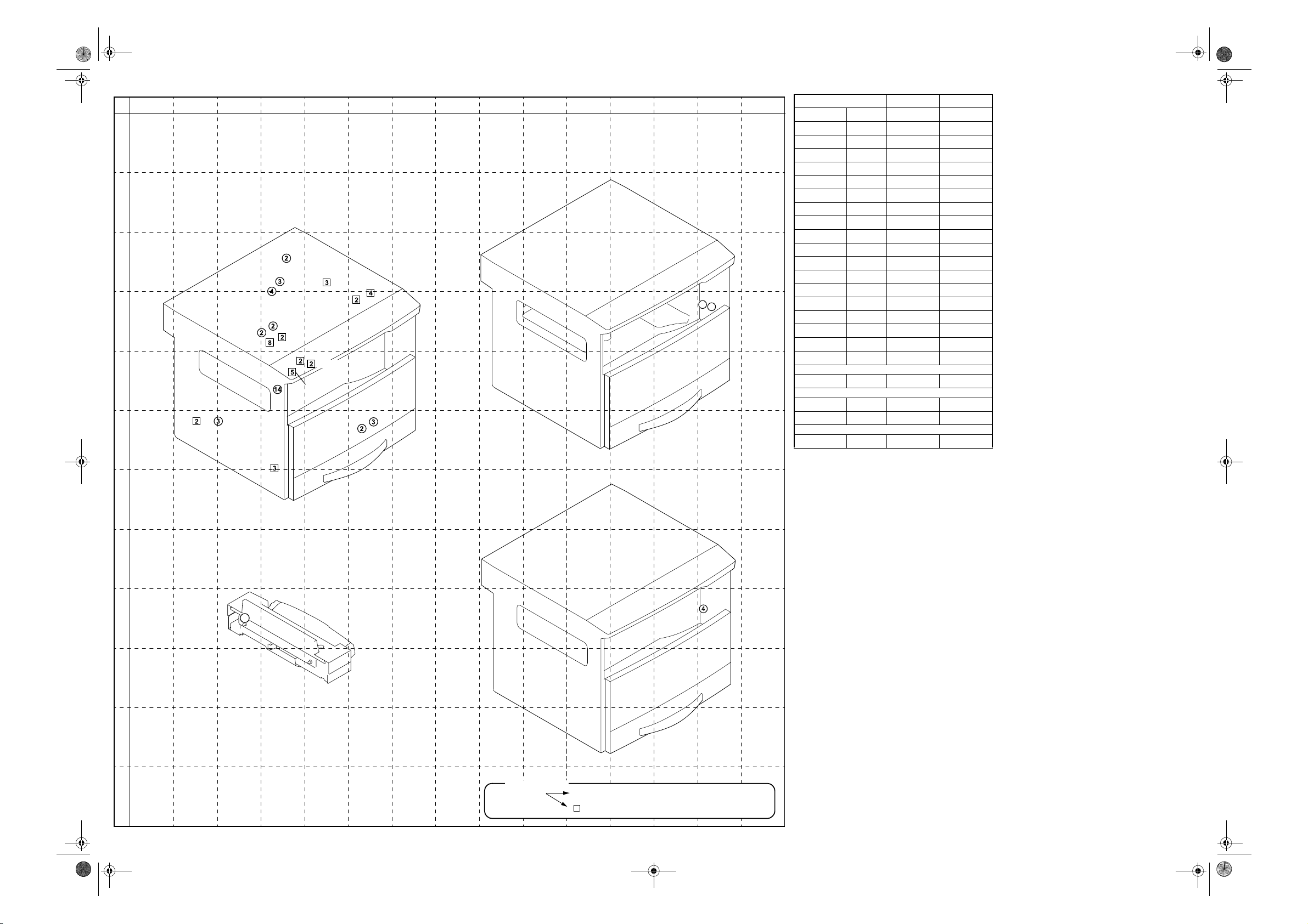
ELECTRICAL PARTS LAYOUT
A
Job Tray (JS-202)
PC35
PWB-A
PC32
PC33
PC34
M1
4689M002AB
M1
S11
M5
S2
PWB-R1
CL1
SL2
PC3
PWB-R2
PC1
UN1
PU1
TH1
PWB-J
PC4
TS1
M3
S10
UN2
PC2
PC7
S4
4021M064AA
H1
LA1
S3
M6
B
PU2
LA2
PC6
PWB-C
SL1
C
D
PWB-A
R1
E
HV1
PWB-I
PC5
S1
F
PH
M4
G
Shifting Unit (OT-103)
H
MultipIe Bypass (MB-5)
PWB-A
SL21
M1
I
S31
J
PC21
K
L
4687M001AB
4690M001AA
PWB-B
SYMBOL PART NAME LOCA TION GRID
CL1 Synchronizing Roller Clutch 1-E 4-D
CNT1 Total Counter (Option) 17-I —
CNT2 Key Counter (Option) 17-I —
H1 Fusing Heater Lamp 1-D 4~6-C~D
HV1 High Voltage Unit 4~5-C~D 3~4-D~E
LA1 Main Erase 4~5-A 5~6-D~E
LA2 Exposure Lamp 11-F 2~4-C~D
M1 Main Motor 16~17-G 4-C~D
M2 Polygon Motor
M3 Fusing Coolin g Fan Motor 1- C 5~6-C
Power Supply Cooling Fan
M4
Motor
M5 Scanner Moto r 11-B 4-B
M6 Toner Replenishing Motor 4-B 6-E
PC1 Synchronizing Roller Sensor 1-E~F 5-E
PC2 Manual Feed Paper Sensor 1~2-A 6-E
PC3 Exit Paper Sensor 1-F 5-C
PC4 Paper Empty Sensor 1-I 5-E
PC5 Drawer Set Sensor 1-I 3-E
Scanner Home Position
PC6
Sensor
Toner Bottle Home Position
PC7
Sensor
PU1 DC Power Supply 10~12-G~I 3~5-E~F
PU2 Inverter Board 12~13-F 3-C~D
PWB-A Master Board 4~8-E~H 3-D~E
PWB-B LD Board
PWB-C Control Board 11~14-A~E 3-C~D
PWB-I Paper Size Detecting Board 1~2-H 2~3-E
PWB-J CCD Board 7~8-A~B 5~6-B~C
PWB-R1 Fusing Board 1~2-D~E 4-C
PWB-R2 Pre-Image Transfer Board 1~2-G 5-D
R1 Flickerless Resistor
S1 Main Switch 16~17-G 3-E
S2 Fusing Unit Interlock Switch
S3 Front Door Interlock Switch 16~17-H 6-E
S4 Right Door Interlock Switch 16~17-H 6-E
S10 Size Reset Switch 9-C 6-C
S11 Paper Size Detecting Sensor 1-H 3-E
SL1 Paper Take-Up Solenoid 1-I 4-D
SL2 Manual Bypass Solenoi d 1-B 4-D
TH1 Thermistor 2-C 5-C
TS1 Thermoswitch 2-D 5~6-D
UN1 ATDC Sensor 4~A 5-D
UN2 Control Panel 7~8-B~C 4~7-C~D
Multiple Bypass (Option)
Multi Feed Bypass Paper
PC21
Empty Sensor
SL21 Multiple Bypass Solenoid 17-F 3-I
Job Tray (Option)
M1 Bin Switchin g M otor 16-A 1 4-D
PC32 Upper Home Position Sensor 16-B 13-D
PC33 Lower Home Position Sensor 16-B~C 13-D
PC34 Full Detecting Sensor 16-C 12-C
PC35 Paper Empty Sensor 17~18-A 12-C
PWB-A Main Board 16~17-A~C 12-C
PWB-B Paper Detecting Boa rd 18-C 14-D
Shifting Unit (Option)
PWB-A Main Board 16~17-D~E 12 ~13-I
M1 Shift Motor 16-D 13-I
S31 Home Sensor 17-D 13-I
✽
1: Components used in the PH Unit
✽
2: 200 V AREAS Only
✽1
✽1
✽2
8-D —
11-I 3~4-F
14-A 2-C
4~5-B 6-E
10~11-E~F —
12-G 2-D~E
16~17-G~H
16~17-F 5-J
4-C
4021-B301-0A
Page 5
Connect.fm Page 1 Wednesday, September 12, 2001 10:47 PM
12345678910111213 1514
CONNECTORS LAYOUT
A
Job Tray (JS-202)
B
CN2
C
CN17
CN15
D
CN13
E
CN3
CN1
CN12
CN25
CN14
CN22
CN21
CN11
CN26
CN16
CN19
CN18
CN20
CN24
F
CN56
CN27
4
2
4689M001AA
CN No. LOCATION GRID
CN1 3P 11-I 2~3-F
CN2 2P 2-D 4-C
CN3 2P 11-G 2-F
CN11 5P 2-A 4-E
CN12 8P 5-A 4-D
CN13 2P 2-I 3~4-D
CN14 2P 2-E 4-D
CN15 4P 2-C~D 4-C~D
CN16 3P 2-C 5-C
CN17 3P 2-F 4-C
CN18 2P 5-B 6-F
CN19 2P 16-I 6-D
CN20 4P 16-I 6-C~D
CN21 2P 2-B 4-E
CN22 2P 5-A 4-D
CN23 3P 11-I 4-F~G
CN24 3P 5-B 6-F
CN25 14P 13-H 4-E
CN26 2P 2-B 5-E
Multiple Bypass (Option)
CN54 2P 16-F 3-I
Job Tray (Option)
CN27 2P 18-C 14-D
CN56 4P 16-A 14-D
Shifting Unit (Option)
CN55 4P 16-C~D 14-I
CN23
G
H
I
Multiple Bypass (MB-5)
CN54
2
4021D004AA
Shifting Unit (OT-103)
CN55
J
4687M002AC
K
4690M002AB
Description
L
Number of Pin Possible to confirm by removing external cover.
➀
Not possible to co nf i rm by removing external cover.
1
4021-B401-0A
Page 6

Page 7

Page 8

Page 9

Page 10

 Loading...