

Page 1

EP1054/EP1085/EP2030
MECHANICAL/
ELECTRICAL
I
MINOLTA
Page 2
COTNENTS
I. CROSS-SECTIONAL VIEW
l-l. Cross-Sectional View of 23 cpm
I-2. Cross-Sectional View of I8 cpm Copier
l-3. Cross-Sectional View of 15 cpm
2. COPY PROCESS
3. DRIVE SYSTEM
4. SEQUENTIAL EXPLANATION
5. IMAGING UNIT
5-l. Imaging Unit Drive
5-2.
Imaging Unit Toner
5-3. Imaging Unit Fuse
6. PC DRUM
7. DRUM CHARGING
8. IMAGE ERASE LAMP
9. OPTICAL SECTION
9-I. Exposure Lamp
9-2. AE Sensor
9-3. Lamp Reflectors
9-4. Aperture Plates
9-5.
Scanner and 2nd/3rd Mirror Carriage Movement
9-6. 4th Mirror Movement
9-7. Lens
IO. ORIGINAL SIZE DETECTING SENSORS (23 cpm COPIER ONLY) . . . . . . . . . . . . . . M-28
1 O-I. Original Size Detecting Sensors
1 O-2. Original Size Detecting Operation
I O-3. Sensor Locations
1 O-4. Size Detection
1 O-5. Original Size Detection Timing
I O-6. Original Cover Angle Detection (23 cpm Copier Only)
11. DEVELOPMENT
11-l.
ATDC Sensor
I I-2. Magnet Roller
I l-3. Developing Bias
I I-4. Doctor Blade
1 I-5. Sleeve/Magnet Roller Lower Filter
12. TONER HOPPER
12-l. Toner Hopper Locking/Unlocking
12-2. Toner Replenishing
12-3. Shutter
12-4. Toner Hopper Home Position Detection
12-5.
Toner Bottle Vibration
12-6. Toner Replenishing Control
13. PAPER TAKE-UP/FEED SECTION (2ND DRAWER: 23 cpm
COPIER ONLY)
13-I
.Edge
13-2.Drawer Positioning
. . . . . . . . . . . . . . . . . . . . . . . . . . . . . . . . . . . . . . . . . . . . . . . . . . . . . . . . . . . . . . . . . . . . . . . . . . . . . . . . . . . . . . . . . . . .
. . . . . . . . . . . . . . . . . . . . . . . . . . . . . . . . . . . . . . . . . . . . . . . . . . . . . . . . . . . . . . . . . . . . . . . . . . . . . . . . . . . . . . . . . . . . . .
*...............................................................................................
. . . . . . . . . . . . . . . . . . . . . . . . . . . . . . . . . . . . . . . . . . . . . . . . . . . . . . . . . . . . . . . . . . . . . . . . . . . . . . . . . . . . . . . . . . . . . . . . . . . . . . . .
. . . . . . . . . . . . . . . . . . . . . . . . . . . . . . . . . . . . . . . . . . . . . . . . . . . . . . . . . . . . . . . . . . . . . . ...*....
. . . . . . . . . . . . . . . . . . . . . . . . . . . . . . . . . . . . . . . . . . . . . . . . . . . . . . . . . . . . . . . . . . . . . . . . . . . . . . . . . . . . . . . . . . . . . . .
Movement
. . . . . . . . . . . . . . . . . . . . . . . . . . . . . . . . . . . . . . . . . . . . . . . . . . . . . . . . . . . . . . . . . . . . . . . . . . . . . . . . . .
. . . . . . . . . . . . . . . . . . . . . . . . . . . . . . . . . . . . . . . . . . . . . . . . . . . . . . . . . . . . . . . . . . . . . . . . . . . . . . . .
. . . . . . . . . . . . . . . . . . . . . . . . . . . . . . . . . . . . . . . . . . . . . . . . . . . . . . . . . . . . . . . . . . . . . . . . . . . . . . . . . .
. . . . . . . . . . . . . . . . . . . . . . . . . . . . . . . . . . . . . . . . . . . . . . . . . . . . . . . . . . . . . . . . . . . . . . . . . . . . . . . . . . . . . . . . . . . . . . . . . . . .
. . . . . . . . . . . . . . . . . . . . . . . . . . . . . . . . . . . . . . . . . . . . . . . . . . . . . . . . . . . . . . . . . . . . . . . . . . . . . . . . . . . . . . . . . . . . . . .
Guide and Trailing Edge Stop
. . . . . . . . . . . . . . . . . . . . . . . . . . . . . . . . . . . . . . . . . . . . . . . . . . . . . . . . . . . . . . . . . . . . . . . . . . . .
. . . . . . . . . . . . . . . . . . . . . . . . . . . . . . . . . . . . . . . . . . . . . . . . . . M-I
Copier
. . . . . . . . . . . . . . . . . . . . . . . . . . . . . . . . . . . . . . . . . . . . . . . . . .
Copier
. . . . . . . . . . . . . . . . . . . . . . . . . . . . . . . . . . . . . . . . . . . . . . . . . . M-3
. . . . . . . . . . . . . . . . . . . . . . . . . . . . . . . . . . . . . . . . . . . . . . . . . . . . . . . . . . . . . . . . . . . . . . . .
. . . . . . . . . . . . . . . . . . . . . . . . . . . . . . . . . . . . . . . . . . . . . . . . . . . . . . . . . . . . . . . . . . . . . . . . . . . . . . . . . . .
Recycling
. . . . . . . . . . . . . . . . . . . . . . . . . . . . . . . . . . . . . . . . . . . . . . . . . . . . . . . . . . . . . . . . . . . . . . . . . . .
. . . . . . . . . . . . . . . . . . . . . . . . . . . . . . . . . . . . . . . . . . . . . . . . . . . . . . . . . . . . . . . . . . . . . . . . . . . . . . . . . . . . .
. . . . . . . . . . . . . . . . . . . . . . . . . . . . . . . . . . . . . . . . . . . . . . . . . . . . . . . . . . . . . . . . . . . . . . . . . .
. . . . . . . . . . . . . . . . . . . . . . . . . . . . . . . . . . . . . . . . . . . . . . . . . . . . . . . . . . . . . . . . . . . . . . . . . . .
. . . . . . . . . . . . . . . . . . . . . . . . . . . . . . . . . . . . . . . . . . . . . . . . . . . . . . . . . . . . . . . . . . . . . . . . . . . . . . . . . . . . . .
. . . . . . . . . . . . . . . . . . . . . . . . . . . . . . . . . . . . . . . . . . . . . . . . . . . . . . . . . . . . . . . . . . . . . . . . . . .
. . . . . . . . . . . . . . . . . . . . . . . . . . . . . . . . . . . . . . . . . . . . . . . . . . . . . . . . . . . . . . . . . . . . . . . . . . . . . . .
. . . . . . . . . . . . . . . . . . . . . . . . . . . . . . . . . . . . . . . . . . . . . . . . . . . . . . . . . . . . . . . . . . . . . . . . . . . . . . . . . . . . . . M-27
. . . . . . . . . . . . . . . . . . . . . . . . . . . . . . . . . . . . . . . . . . . . . . . . . . . . . . . . . . . . . . . . . . . . . . . . . . . . . . . . . . . .
. . . . . . . . . . . . . . . . . . . . . . . . . . . . . . . . . . . . . . . . . . . . . . . . . . . . . . . . . . . . . . . . . . . . . . . . . . . . . . . . . . . . . . . .
. . . . . . . . . . . . . . . . . . . . . . . . . . . . . . . . . . . . . . . . . . . . . . . . . . . . . . . . . . . . . . . . . . . . . . . . . . . . . . . . . . . . . . . . .
. . . . . . . . . . . . . . . . . . . . . . . . . . . . . . . . . . . . . . . . . . . . . . . . . . . . . . . . . . . . . . . . . . . . . . . . . . . . .
. . . . . . . . . . . . . . . . . . . . . . . . . . . . . . . . . . . . . . . . . . . . . . . . . . . . . . . . . . . . . . . . . . . . . . . . . . . . . . . . . . . . . .
. . . . . . . . . . . . . . . . . . . . . . . . . . . . . . . . . . . . . . . . . . . . . . . . . . . . . . . . . . . . . . . . . . . . . . . . . . . . . . . .
. . . . . . . . . . . . . . . . . . . . . . . . . . . . . . . . . . . . . . . . . . . . . . . . . . . . . . . . . . . . . . . . . . . . . . . . . . . . . . . . . .
. . . . . . . . . . . . . . . . . . . . . . . . . . . . . . . . . . . . . . . . . . . . . . . . . . . . . . . . . . . . . . . . . M-I 4
. . . . . . . . . . . . . . M-20
. . . . . . . . . . . . . . . . . . . . . . . . . . . . . . . . . . . M-24
. . . . . . . . . . . . . . . . . . . . . . . . . . . . . . . . . . . . . . . . . . . . . . . . . . . . . . . . . . . . .
. . . . . . . . . . . . . . . . . . . . . . . . . . . . . . . . . . . . . . . . . . . . . . . . . . . . . . . . . .
. . . . . . . . . . . . . . . . . . . . . . . . . . . . . . . . . . . . . . . . . . . . . . . . . . . . . . . . . . . . . . .
. . . . . . . . . . . . . . . . . . . . . . . . . . . M-32
. . . . . . . . . . . . . . . . . . . . . . . . . . . . . . . . . . .
. . . . . . . . . . . . . . . . . . . . . . . . . . . . . . . . . . . . . . . . . . . . . . . . . . . . . . . . . . .
. . . . . . . . . . . . . . . . . . . . . . . . . . . . . . . . . . . . . . . . . . . . . . . . .
. . . . . . . . . . . . . . . . . . . . . . . . . . . . . . . . . . . . . . . . . . . . . . . . . . . . . . . . . . . . . . . . . . . . . . . . . . . . . M-41
. . . . . . . . . . . . . . . . . . . . . . . . . . . . . . . . . . . . . . . . . . . . . . . . . . . . . . . . . . . . . . . . . . . .
. . . . . . . . . . . . . . . . . . . . . . . . . . . . . . . . . . . . . . . . . . . . . . . . . . . . . . . .
M-l
M-2
M-4
M-6
M-7
M-12
M-13
. . . . . . . . . M-14
M-15
. . . . . . . . . . . . M-16
M-17
. . . . . . . . . . . . M-21
M-22
M-23
. . . . . . . . . . . . M-23
M-26
M-28
M-28
M-29
M-30
M-31
. . . . . . . . . . . . M-33
M-34
. . . . . . . . . . . . M-36
M-37
. . . . . . . . . . . M-38
.._...................
M-38
. . . . . . . . . . M-39
M-39
M-39
M-40
M-40
M-42
M-43
M-44
M-45
Page 3
13-3.Paper Lifting Plate
13-4.Drawer-in-Position Detection
13-5.Universal Tray (1 st Drawer) Paper Size Detection
13-6.Paper Empty Detection
13-7.Paper Separating Mechanism
13-8.Paper Take-Up Roll
13-9.Paper Take-Up Retry Control
13-lO.VERTICAL
14.
MULTI BYPASS TABLE
14-1 .Paper Take-Up
14-2.Paper Take-Up Retry Control
14-3.Paper Separating Mechanism
14-4.Paper
15.
SYNCHRONIZING
15-l .Upper Synchronizing Roller Positioning
15-2.Paper Dust Remover
15-3.Synchronizing
16. IMAGE TRANSFER AND PAPER SEPARATION
17. MAIN ERASE LAMP
18. PAPER SEPARATOR FINGERS
19.
CLEANING
19-l .Cleaning Bias
20. PAPER TRANSPORT
21. FUSING UNIT
21-1. Fusing Temperature Control
21-2.Fusing
21-3.Cleaning
22. EXIT UNIT
22-l .Upper/Lower Separator
22-2.Paper Exit Sensor
23. EXIT/DUPLEX SWITCHING UNIT (OPTION)
24. DEHUMIDIFYING SWITCH
25. COOLING
26. OPTICAL SECTION COOLING FAN
27. MEMORY BACKUP
Empty
UNIT
..................................................................................................
Rollers Pressure
Roller
.......................................................................................................
FAN
...................................................................................
...................................................................
............................................................................
.................................................................
.................................................................................
..................................................................
PAPER TRANSPORT
..................................................................................
Mechanism .....................................................................
Detection
ROLLERS
Roller Control
.............................................................................................
................................................................................................
............................................................................
.........................................................................
...............................................................................
........................................................................................
..........................................................................................
.....................................................................................
Mechanism
........................................................................................
Fingers
....................................................................................
(OPTION)
.........................................................................................
.........................................................
..................................................................
.................................................................
..................................................
...................................................................
....................................................................
...................................................................
.......................................................
..............................................................
............................................................
...............................................................
..................................
...........................................
.................................................
M-45
M-46
M-47
M-40
M-49
M-50
M-51
M-52
M-53
M-54
M-55
M-56
M-56
M-57
M-58
M-58
M-59
M-60
M-62
M-63
M-64
M-65
M-66
M-67
M-68
M-69
M-69
M-70
M-70
M-71
M-72
M-73
M-74
M-75
M-76
ii
Page 4
FrameMaker Ver.5.5(PC) EP1054/EP1085/EP2030 MECHANICAL/ELECTRICAL
98.04.24
1174SBM0100A
1 CROSS-SECTIONAL VIEW
1174SBM0101A
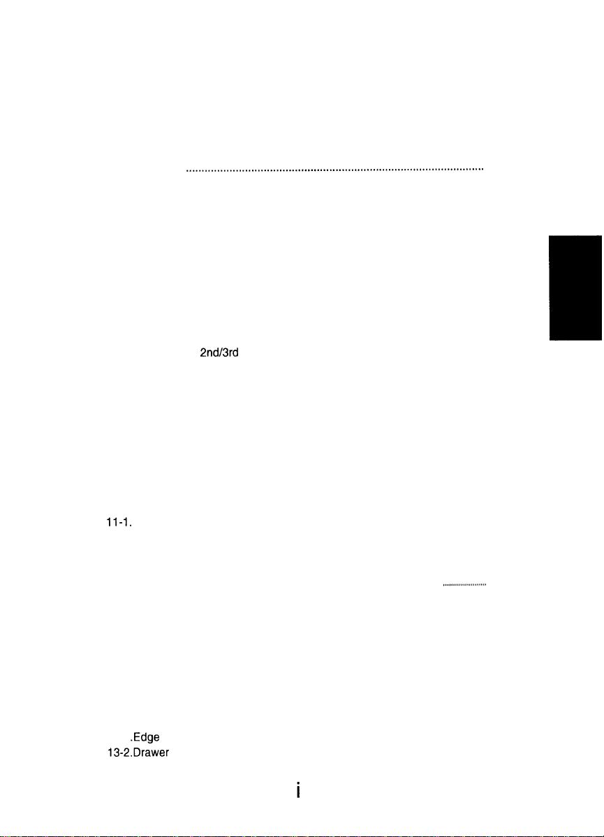
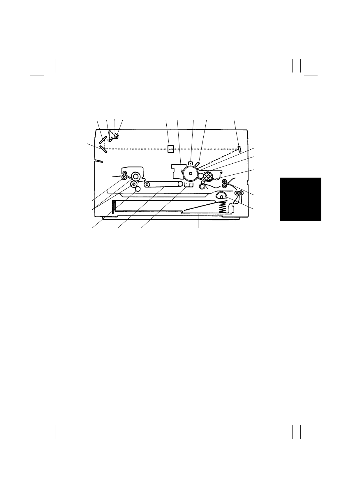
1-1. Cross-Sectional View of 23 cpm Copier
2345 6 7 8 9 10
1
22
21
20
23
19
18
24
1. 3rd Mirror
2nd Mirror
2.
3. 1st Mirror
4. Exposure Lamp
5. Lamp Reflector
6. Lens
7. Cleaning Blade
8. PC Drum Charge Corona
9. Image Erase Lamp
10. 4th Mirror
11. PC Drum
12. Sleeve/Magnet Roller
13. Synchronizing Roller
14. Trans port Roller
15. 1st/2nd Drawer Paper Take-Up Roll
16. 1st/2nd Drawer
1617
17. Image Transfer/Paper Separator
Coronas
18. Suction Unit
19. Cleaning Roller
20. Upper/Lower Fusing Roller
21. Paper Exit Rol ler
22. Exit/Duplex Switching Guide
(for optional Duplex Uni t and Sorter)
23. Duplex Unit Vertical Tr ansport Roller 1
(for optional Duplex Unit )
24. Duplex Unit Vertical T ransport Roller 2
(for optional Duplex Unit )
1174M005AB
11
12
13
14
15
M-1
Page 5
FrameMaker Ver.5.5(PC) EP1054/EP1085/EP2030 GENERAL, MECHANICAL/ELECTRICAL
98.04.24
1174SBM0102A
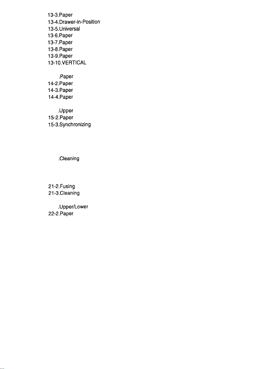
1-2. Cross-Sectional View of 18 cpm Copier
2345 6 7 8 9 10
1
23
22
21
20
19 18 17 16
1. 3rd Mirror
2. 2nd Mirror
3. 1st Mirror
4. Exposure Lamp
5. Lamp Reflector
6. Lens
7. Cleaning Blade
8. PC Drum Charge Corona
9. Image Erase Lamp
10. 4th Mirror
11. PC Drum
12. Sleeve/Magnet Roller
13. Synchronizing Roller
14. Trans port Roller
15. Paper Take-Up Roll
16. Drawe
17. Image Transfer/Paper Separator
18. Suction Unit
19. Cleaning Roller
20. Upper/Lower Fusing Roller
21. Paper Exit Rol ler
22. Exit/Duplex Switching Guide
23. Paper Exit Roller in Exit/Duplex
11
12
13
14
15
1174M004AB
Coronas
(for optional Sorter)
Switching Guide Unit
(for optional Sorter)
M-2
Page 6
FrameMaker Ver.5.5(PC) EP1054/EP1085/EP2030 MECHANICAL/ELECTRICAL
98.04.24
1174SBM0103A
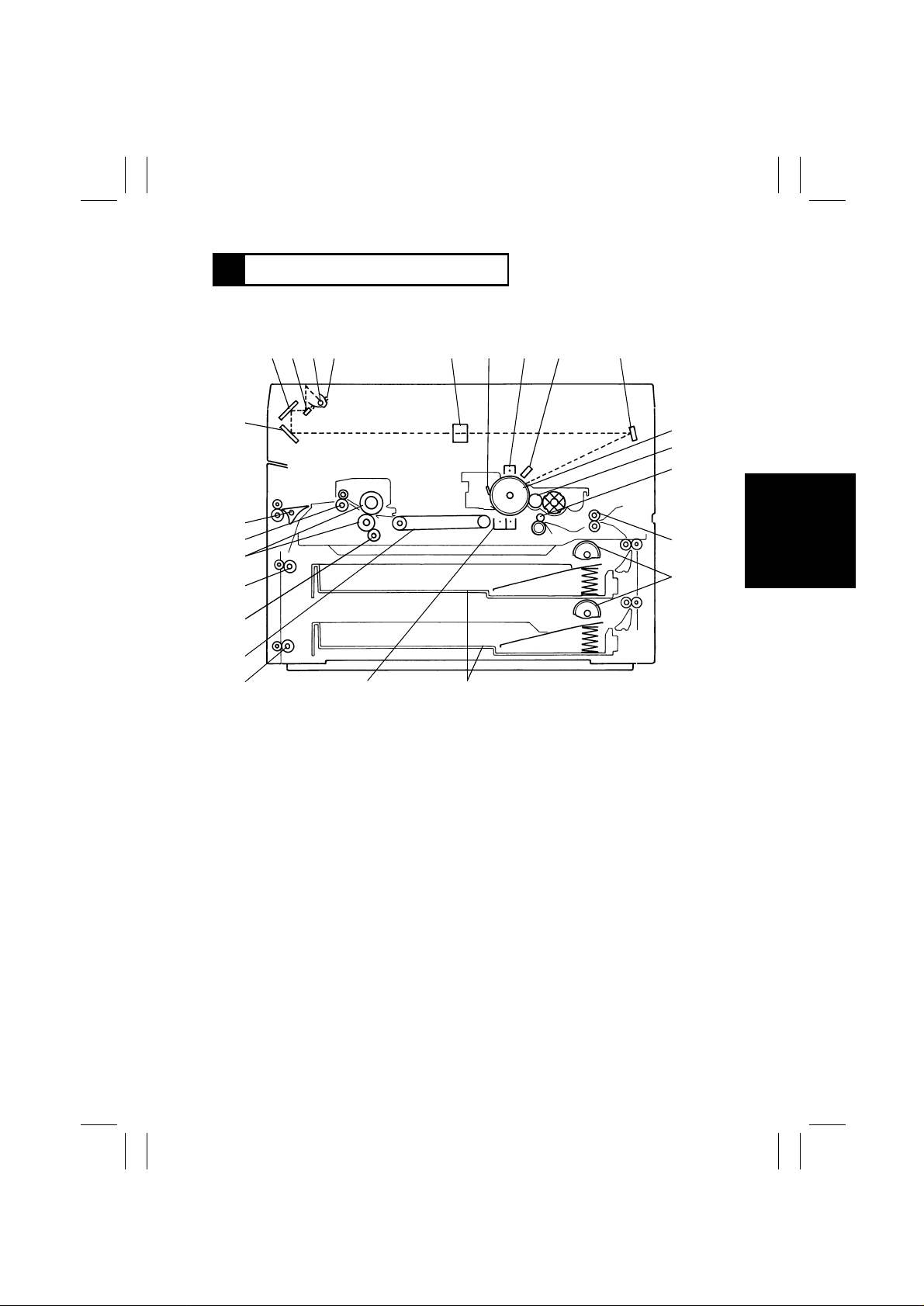
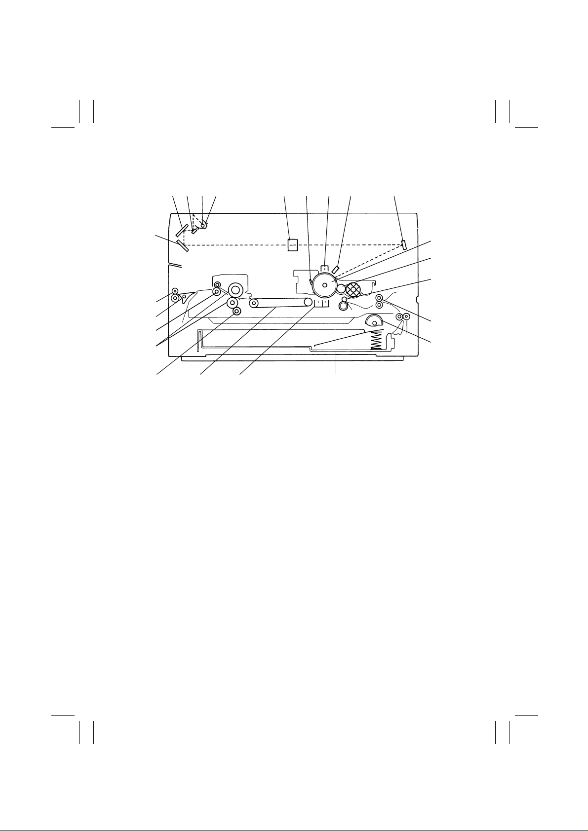
1-3. Cross-Sectional View of 15 cpm Copier
Except U.S.A., Canada
✽
2345 6 7 8 9 10
1
21
20
19 18 17 16
1. 3rd Mirror
2. 2nd Mirror
3. 1st Mirror
4. Exposure Lamp
5. Lamp Reflector
6. Lens
7. Cleaning Blade
8. PC Drum Charge Corona
9. Image Erase Lamp
10. 4th Mirror
11. PC Drum
12. Sleeve/Magnet Roller
13. Synchronizing R ol ler
14. Transport Roller
15. Paper Take-Up Roll
16. Drawer
17. Image Transfer/Paper Separator
18. Suction Unit
19. Cleaning Roller
20. Upper/Lower Fusing Roller
21. Paper Exit Rol ler
11
12
13
14
15
1174M011AA
Coronas
M-3
Page 7
FrameMaker Ver.5.5(PC) EP1054/EP1085/EP2030 GENERAL, MECHANICAL/ELECTRICAL
98.04.24
1174SBM0200A
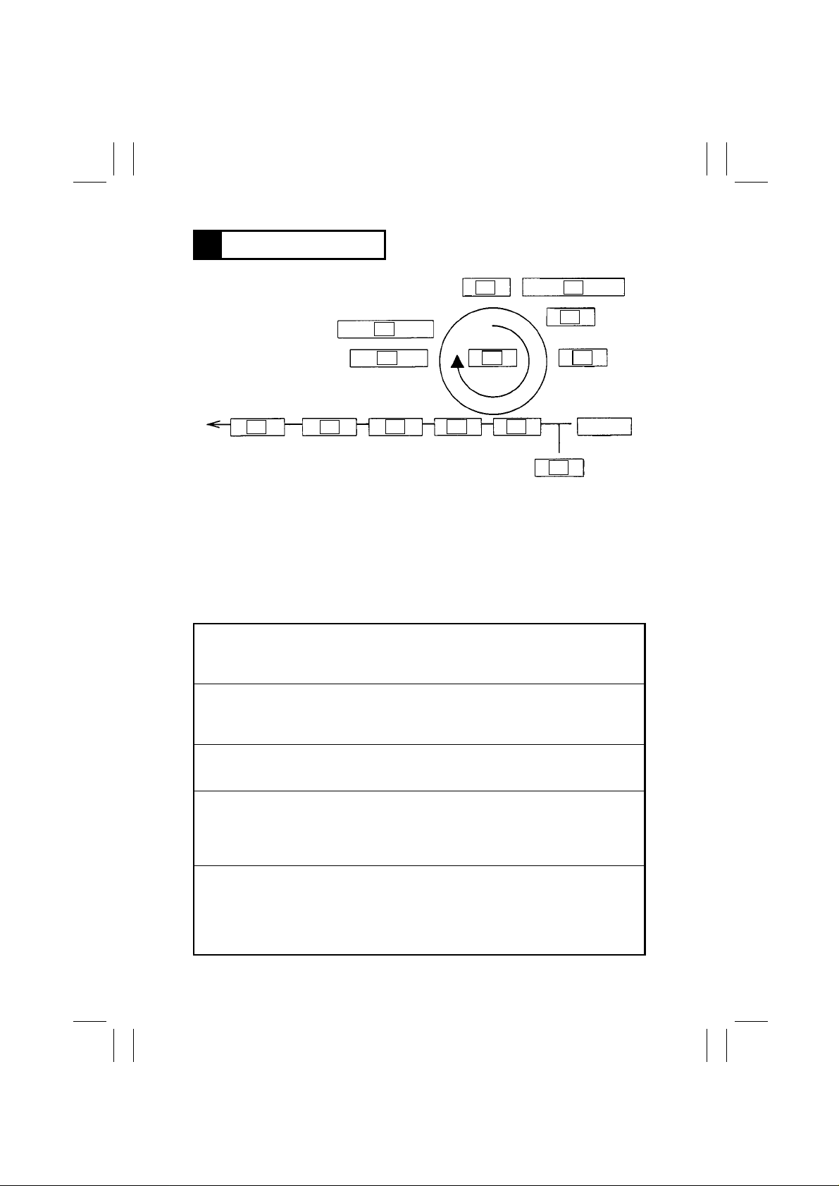
2 COPY PROCESS
2 3
6
4
5
5
MULTI BYPASS
T ABLE
1139M002AA
13
1. PC DRUM
2. DRUM CHARGING
3. IMAGE ERASE
4. EXPOSURE
5. DE VELOPING
6. PAPER FEEDING
10
9
12
11
1
8
8
7
7
8. PAPER SEPARAT ION
9. CLEANING
10.MAIN ERASE
11. TRANSPORT
12. FUSING
13.PAPER EXIT
7. IMAGE TRANSFER
1. PC Drum
The PC Drum is an aluminum cylinder coated with a photosensitive semiconductor.
It is used as the medium on which a visib l e developed image of the original is formed.
(For more details, see “6. PC DRUM”.)
2. Drum Charging
The PC Drum Charge Coron a U nit is equipped wit h a Co mb Electrode and a Scorotron
Grid to deposit a uniform negative charge across th e entire surf ace of the PC Drum.
(For more details, see “7. DRUM CHARGING”.)
3. Image Erase
Any areas of charge which are not to be developed are neutralized by lighting up LED s.
(For mor e details, see “8. IMAGE ERASE LAMP”. )
4. Exposure
Light from the Exposure Lamp reflect ed off the original is gui ded to the surface of the PC
Drum and reduces the level of the negative charges, thereby forming an electrostatic
latent image.
(For mor e details, see “9. OPTICAL SECTION”.)
5. Developing
Toner positively charged in the Developer Mixi ng Chamber is attracted onto the electrostatic lat ent i mage c ha ngin g it to a v is ib le , devel oped i ma ge. A DC negat ive bias v oltag e i s
applied to t he Sle eve/Magn et Roller to pr event toner from being a ttr ac te d onto th os e area s
of the PC Drum which correspond to the background areas of the original .
(For mor e details, see “11. DEVELOPMENT”.)
M-4
Page 8

FrameMaker Ver.5.5(PC) EP1054/EP1085/EP2030 MECHANICAL/ELECTRICAL
98.04.24
6. Paper Feeding
Pape r is fed either au tomatically fro m the 1st or 2nd Drawer, or manually via the Multi
Bypass Table or Manual Bypass Table. Each Dra wer has fingers that function to separate
the top sheet of paper from the rest at take-up. (2nd Drawer: 23 cpm Copier Only )
(For more details, see “13. PAPER TAKE-UP/FEED SECTION”.)
7. Image Transfer
The single-wir e Image Transfer C orona Uni t ap plies a DC neg ati v e c orona emi ssi on to t he
underside of the paper, thereby attracting toner onto the surface of the paper.
(For more details, see “16. IMAGE TRANSFER AND PAPER SEPARATION”.)
8. Paper Separation
The single-wire Paper Separator Cor ona Unit applies an AC corona emission to the
underside o f the p ape r to neutr al i ze t he pap er. In addition, mechanic al paper s epa rati o n is
provided by the two PC Drum Paper Separator Fingers fitted to the Imaging Unit.
(For more details, see “16. IMAGE TRANSFER AND PAPER SEPARATION”.)
9. Cleaning
Residual toner on the surface of the PC Drum is scraped off by the Cleani ng Blade.
(For mor e details, see “19. CLEANING UNIT”.)
10.Main Erase
Light from the Main Erase Lamp neutralizes an y surface potential remaining on the surface of the PC Drum after cleaning.
(For mor e details, see “17. MAIN ERASE LAMP”.)
11. Transport
The paper is fed to the Fusing Unit by the Suction Belts.
(For more details, see “20. PAPER TRANSPORT”.)
12. Fusing
The developed imag e is permanently fused to the paper by a combi nation of heat and
pressure applied by the Upper and Lower Fusing Rolle rs.
(For more details, see “21. FUSING UNIT”.)
13.Paper Exit
After the fusing process the paper is fed out by the Paper Exit Roller onto the Copy Tray.
(For mor e details, see “22. EXIT UNIT”.)
M-5
Page 9
FrameMaker Ver.5.5(PC) EP1054/EP1085/EP2030 GENERAL, MECHANICAL/ELECTRICAL
98.04.24
1174SBM0300A
3 DRIVE SYST EM
This copier is equipped with two main drive motors, the PC Drive Motor that drives the
upper half of the copier (Imaging Unit) and the Main Drive Motor which gives drive for the
lower half of the copier (paper take-up/feeding, transport mechanism and Fusing Unit).
Each has its o wn drive transmitting gears and timing belts as illustrate d bel ow.
Drive Train for Lower Half of Copier
Coupled to Paper
Take-Up Unit
Drive Train for
Paper Take-Up Unit
<23 cpm Copier>
Coupled to Copier Gear
1st Vertical
Transport Roller
2nd Vertical
Transport Roller
1139M004AA
Coupled to Exit/Duplex
Switching Unit
Paper Exit Roller Drive
Suction Unit
Drive
Synchronizing Roller Clutch CL 1
Pape r Transport
Clutch CL 2
<15/18 cpm Copier >
1st Draw er Paper
Take-Up Roll
Vertical
Transport Roller
2nd Drawer P ape r
Take-Up Roll
Main Drive Motor M2
1151M001YB
Drive Train for Upper
Half of Copier
PC Drum Drive
Imaging Uni t
Drive
1139M005 AA
PC Drive Motor M1
Coupled to Copier Gear
Paper D rawer Paper
Take-Up Roll
1142M002AA
Upper Fusing
Roller Drive
M-6
Page 10

FrameMaker Ver.5.5(PC) EP1054/EP1085/EP2030 MECHANICAL/ELECTRICAL
98.04.24
1174SBM0400A
4 SEQUENTIAL EXPLANATION
Numbers given in rectangles in the following flowchart are timer values in seconds.
✽
A The power cord is plugged into the outle t.
Power cord is plugged in.
ON
AC24V for Drum heating (Transformer)
ON
B Power Switch is turned ON.
Power Switch ON
ON
ON
ON
ON
Drum Dehumidifying
Heater
ON
Paper Dehumidifying
Heater
DC5V (Power Supply Unit)
DC24V (Power Supply Unit)
Control panel
The Cooling Fan turns at full speed.
Approx. 3
Approx. 1
ON
ON
ON
The Cooling Fan turns at half speed.
Fusing Heater Lamp
Scanner Reference Position Sensor
Only when Dehumidifying
Switch is ON
✽If the S cann er i s n ot at the home posi ti on, Scan ner Mot or i s
energi z ed to move the Scanner to the home position.
ON
Lens Reference Position Sens or
✽If the Lens is not at the home position, Lens Motor is
ON
energized to move the Lens to the home position.
Mirror Reference Position Sensor
✽If the 4th Mirror is not at the home position, Mirror
Motor is energized to move the Mirror to the home
Start er setup and ATDC Sensor a ut omatic adjustment
position.
✽Only when the Imaging Unit is new. I/U Fuse blows when the
starter setup sequence is completed normally.
M-7
Page 11

FrameMaker Ver.5.5(PC) EP1054/EP1085/EP2030 GENERAL, MECHANICAL/ELECTRICAL
98.04.24
C The Fusing Unit temperature reaches 205°C.
Fusing Thermistor detects 205°C.
ON/OFF
Fusing Heater Lamp
✽The Fusing Unit temperature control is started.
M-8
Page 12

FrameMaker Ver.5.5(PC) EP1054/EP1085/EP2030 MECHANICAL/ELECTRICAL
98.04.24
D The Start Key is pressed.
Start Key ON
ON
PC Drive Motor
ON
ON
ON
Main Erase Lamp
Main Drive Motor
Image Erase Lamp
✽All LEDs are turned ON.
ON
ON
ON
Developing Bias (High Voltage Unit)
Paper Separator Corona (High Voltage Unit)
Cleaning Bias (High Voltage Unit)
✽Some model s ha v e n o Bia s Seal ins tal led de pendi ng o n
ON
their marketing areas.
Synchronizing Roller Clutch ✽For appr ox 0.2 sec. onl y
Approx. 0.3
Approx. 0.2
ON
1st/2nd Drawer Paper Take-Up Solenoid
1st/2nd D r awer Paper Take-Up
Approx. 0.1
ON
PC Drum Charge Corona/Image Transfer Corona
OFF
Solenoid (2nd Drawer Paper TakeUp Solenoid: 23 cpm copier only)
Approx. 0.2
Approx. 2.5
ON
Paper Transport Clutch
ON
Synchr onizing Roller C lutch
E Paper is taken up.
1st/2nd Drawer Paper Take-Up Solenoid ON
(2nd Drawer Paper Take-Up Solenoid: 23 cpm copier only)
Approx. 0.4
1
ON
1st/2nd Drawer Paper Take-Up Sensor
1st Drawer :
Approx. 0.7
2nd Drawer:
Approx. 1.4
(23 cpm copier
Only)
ON
Approx. 0.5
Approx. 0.2
M-9
Transport Roller S ensor
ON
Paper Leading Edge
Detecting Sensor
Approx. 0.2
ON
Exposure Lamp
OFF
Paper
Transport
Clutch
Page 13

FrameMaker Ver.5.5(PC) EP1054/EP1085/EP2030 GENERAL, MECHANICAL/ELECTRICAL
98.04.24
1
ON
Approx. 0.5
Scanner Motor
OFF
Scanner Reference Position Sensor
Approx. 0.2
Approx. 0.5
F A scan motion is completed.
SCEND signal: LOW
Approx. 0.2
Approx. 0.3
ON
All LEDs of Image Erase Lamp ON
Scanner starts return motion.
Approx. 0.6
✽For A4 crosswise, ×1.000
Approx. 0.3
OFF
Exposure Lamp
Image Erase Lamp LEDs ON/OFF control is started.
ON
Synchronizing Roller Clutch
ON
Paper Transport Clutch
ON
Scanne r Reference Positio n Sensor
M-10
Page 14

FrameMaker Ver.5.5(PC) EP1054/EP1085/EP2030 MECHANICAL/ELECTRICAL
98.04.24
G The last paper moves past Transport Roller Sensor.
Transport Roller Sensor OFF
Approx. 0.6
Approx. 0.9
Approx. 1.2
OFF
Paper Leading Edge Detecting Sensor
OFF
Approx. 0.4
Approx. 0.7
Approx. 0.5
ON
1st Paper Exit Sensor
OFF
Paper Transport Clutch
Synchronizing Roller Clutch
OFF
PC Drum Charge Corona/Image Transfer
Corona (High Voltage Unit)
Approx. 0.7
OFF
OFF
OFF
OFF
PC Drive Motor
OFF
Main Erase Lamp
OFF
Image E ra se Lamp
Developing Bias (High Voltage Unit)
Cleaning Bias (High Voltage Unit)
✽Some mode ls have no Bias Seal installed
depending on their marketing areas.
Paper Separator Corona (High Voltage Unit)
H The paper moves past 1st P aper Exit Sensor.
1st Paper Ex i t S ensor OFF
Approx. 1.5
OFF
Main Drive Motor
M-11
Page 15
FrameMaker Ver.5.5(PC) EP1054/EP1085/EP2030 GENERAL, MECHANICAL/ELECTRICAL
98.04.24
1174SBM0500A
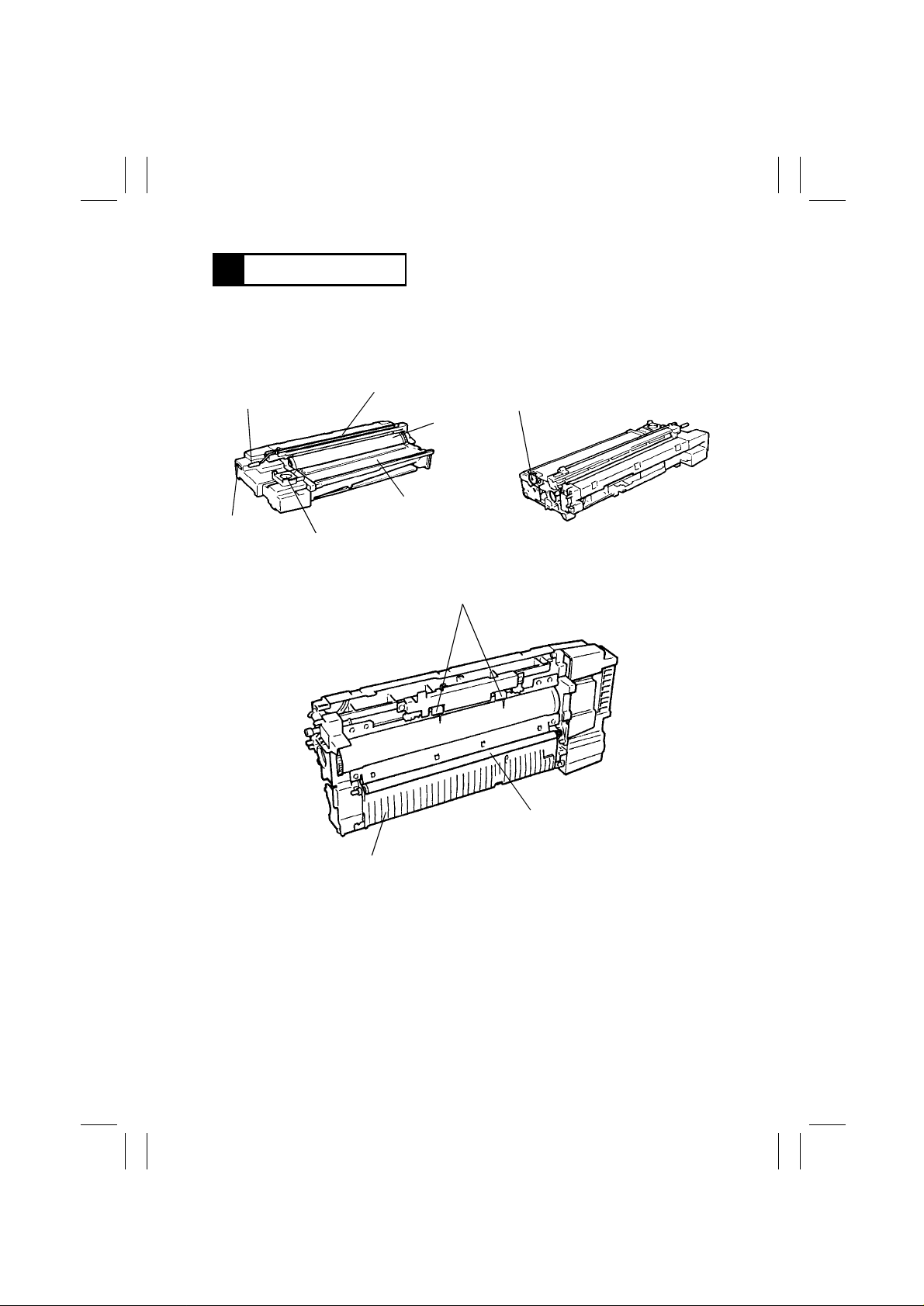
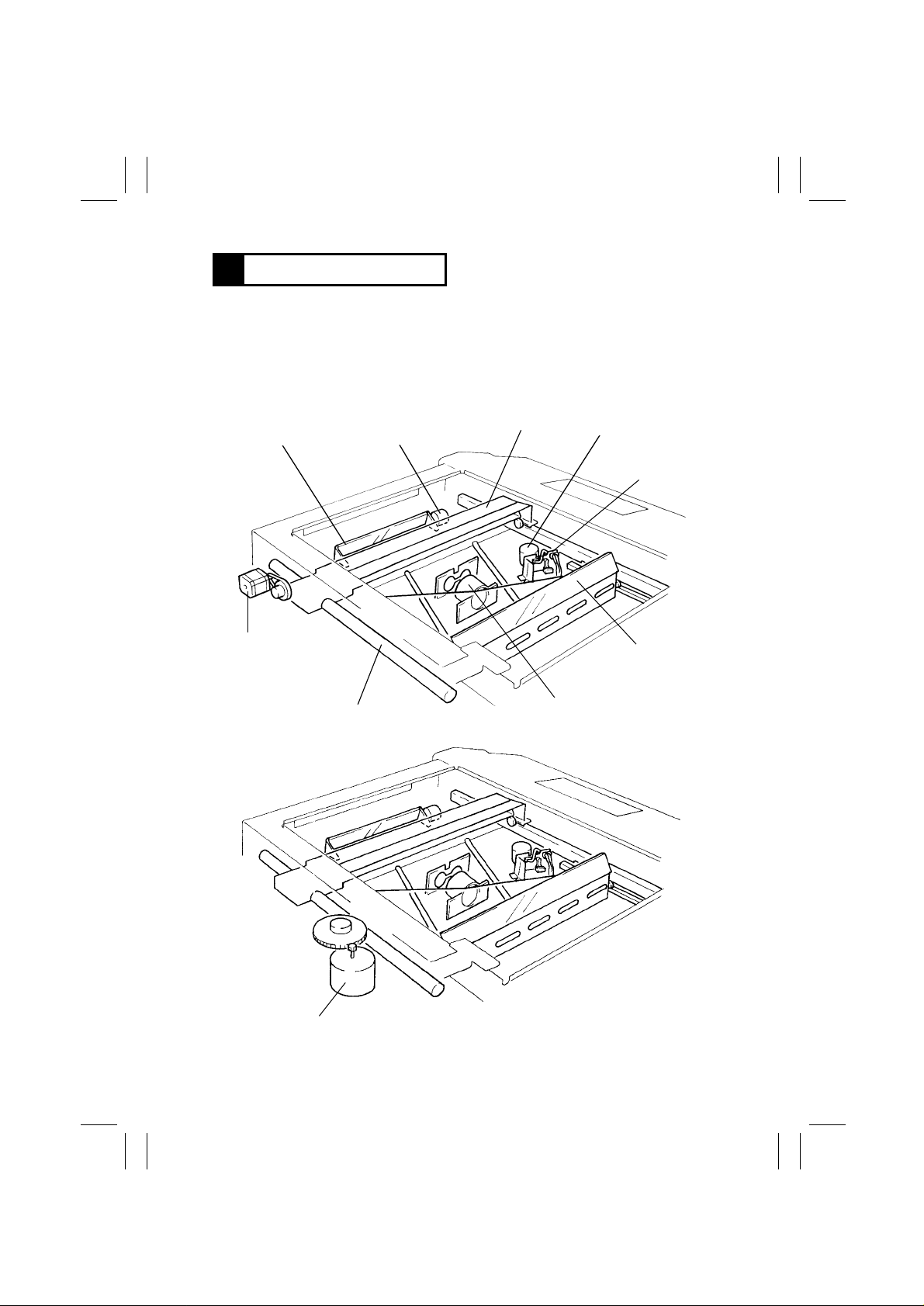
5 IMAGING UNI T
This copier is equipped w ith an Imagi ng U nit, or IU, which in tegrates a PC Drum, PC Drum
Charge Corona, Developing Unit, Cleaning Unit, and Toner Recycling mechanism into one
assembly. The Unit also includes the Upper Synchronizing Roller which facilitates clearing
of a paper misfeed.
Corona Unit Cleaning
Lever
Counter
Toner Supply Port
PC Drum
Charge Corona
Coupled to Gear in
Copier
PC Drum
Developer Mixing Chamber
1139M009AA 1139M010AA
Paper Separator Fingers
Upper Synchronizing Roller
1174M014AA
Paper Guide Plate
M-12
Page 16

FrameMaker Ver.5.5(PC) EP1054/EP1085/EP2030 MECHANICAL/ELECTRICAL
98.04.24
1174SBM0501A
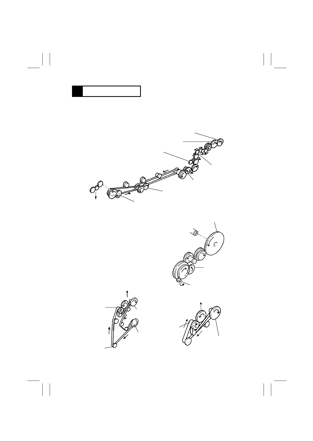
5-1. Imaging Unit Drive
Drive for the Imaging Unit is transmitte d by one of the gears on the Unit.
This particular gear is in mesh with the Imaging Unit Drive Gear in the copier.
Dev eloper Mixing Screw Drive Gear
Bucket Roller Drive Gear
Imaging Unit Drive
Gear (in Copier)
Sleeve/Magnet Roll er
Drive Gear
Coupling (in Copier)
1139M012AA
T oner Recycling Coil
Drive Gears
M-13
Page 17
FrameMaker Ver.5.5(PC) EP1054/EP1085/EP2030 GENERAL, MECHANICAL/ELECTRICAL
98.04.24
1174SBM0502A
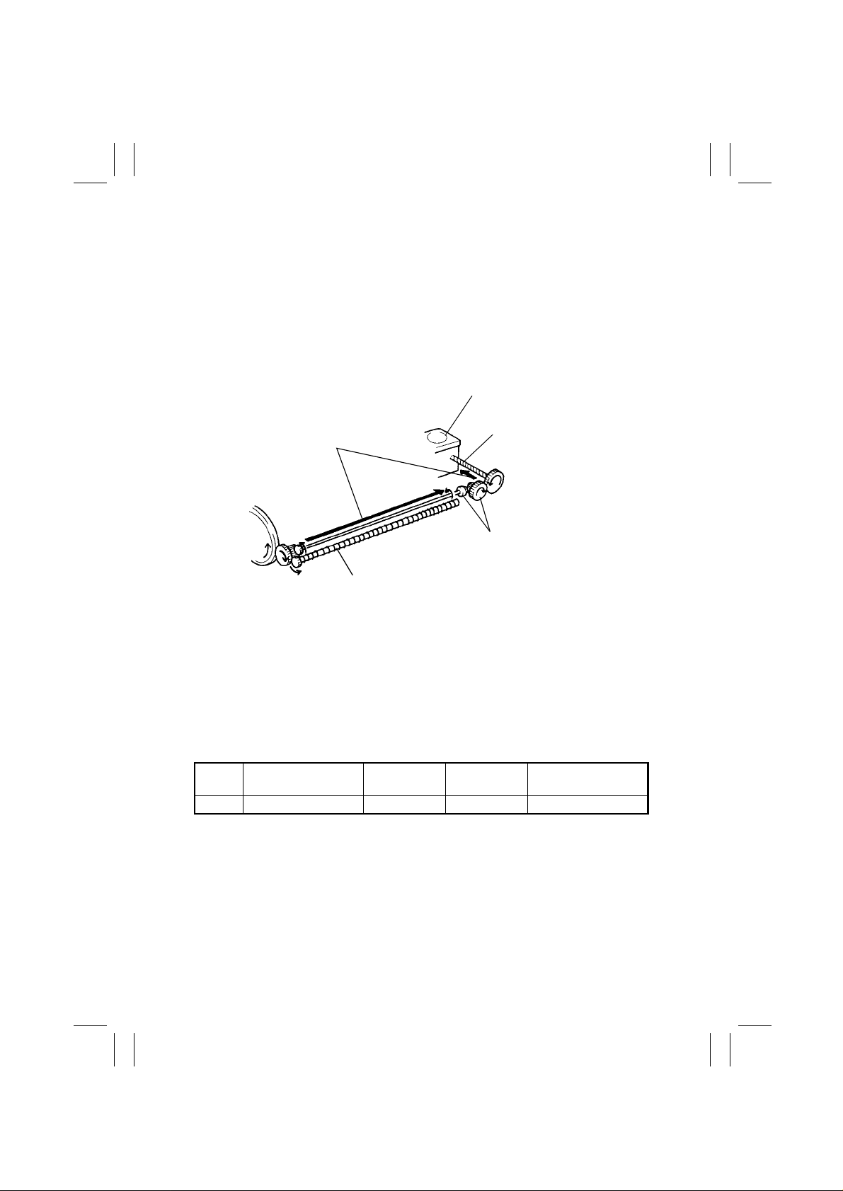
5-2. Imaging Unit Toner Recycling
The copier is provided with a ton er recycling mechanism . The toner, which has been
scraped o ff t he surface of the PC Drum by the C lean ing Bla de and c olle cted in t he Clean ing
Unit, is conv e y ed by the tw o Toner Recycling Coils t o the Toner Supply Port and, fr om there ,
it is returned back to the Developer Mixing Chamber of the Developing Unit.
One of the gears of the Toner Recycling mechanism rece ives drive through a gear at the
rear end of the PC Drum.
Toner Supply Port
Toner Recycling Path
Toner Recycling Coil
Bev el Gears
1139M013AA
Toner Recycling Coil
1174SBM0503A
5-3. Imaging Unit Fu se
The Imaging Unit is provided with a fuse called the I/U Fuse. When a new Imaging Unit is
installed in the copier and the Power Switch turned ON, an I/U Set signal is output c ausing
the copier t o st art the starter setup sequence and ATDC Sensor automatic adjustment.
When the starter setup sequence is compl eted normally, an I/U Fuse Blow signal is output
to blow the I/U Fuse. Once the I/U Fuse is b lown, the I/U Set signals are no longer output.
This means that the starter setup sequence and ATDC Sensor automatic adjustment will
not be carried out w hen the Po w er Switch is ther eafter turned ON.
Control Signal
When Fuse is
not Blown
Fuse PWB- A PJ 1 0 A- 6 H L 2-I
When Fuse is
Blown
WIRING DIAGRAM
M-14
Page 18
FrameMaker Ver.5.5(PC) EP1054/EP1085/EP2030 MECHANICAL/ELECTRICAL
98.04.24
1174SBM0600A
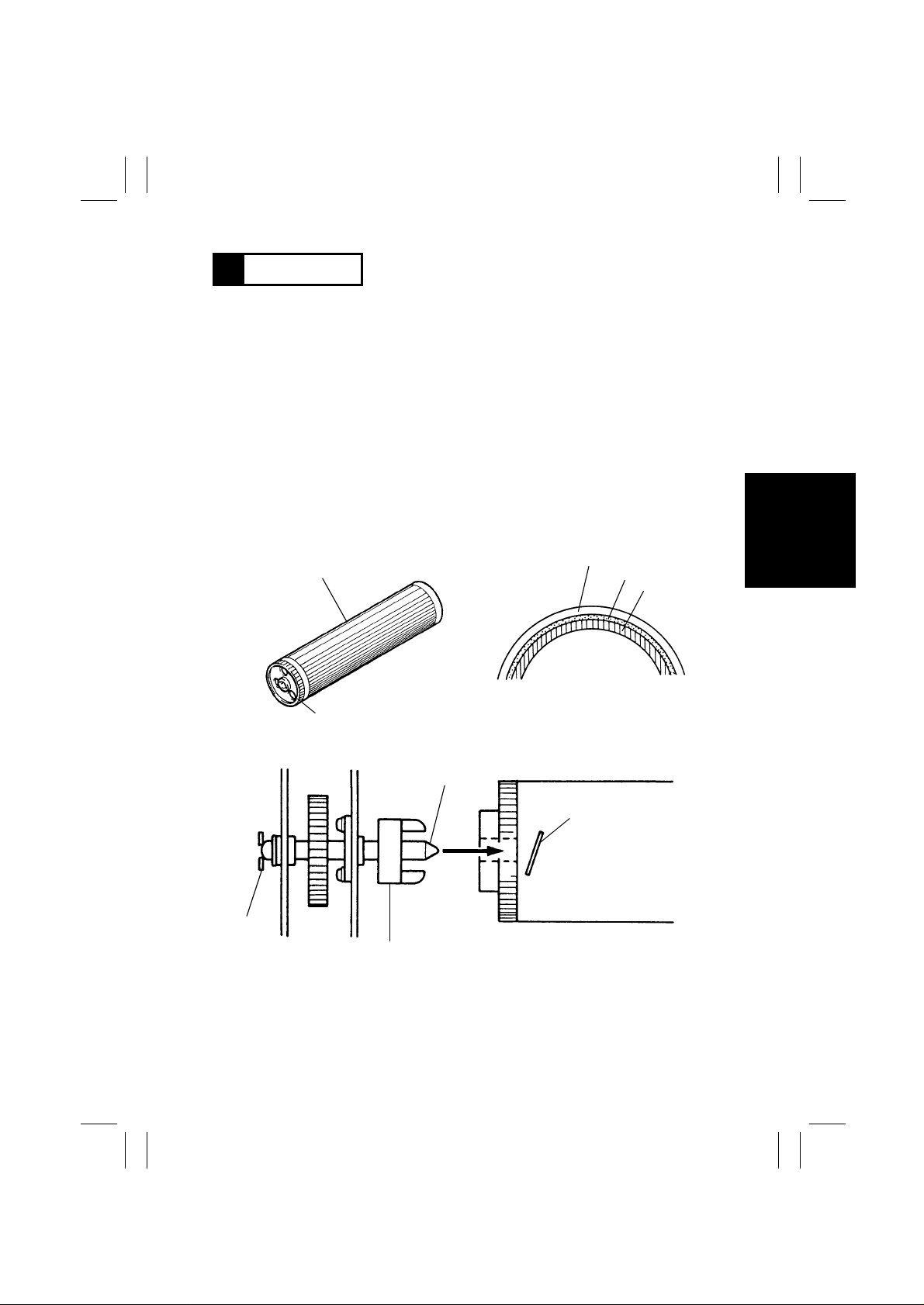
6 PC DRUM
The photoconductive drum used in t his copier is the organi c photoconductor (OPC) type.
The drum is made up of two disti nct, semiconductive materials on an aluminum all oy base.
The outer of the tw o l a yers is calle d the C har ge Transport Lay er ( CTL ), wh il e the i nner layer
is called the Ch arge Generating Layer (CGL).
The PC Drum has its grounding point in side at its rear end. When the Imaging Unit is
installed in the copier, the shaft on which the PC Drum Drive Coupling Gear is mounted
contacts this grounding point.
Handling Precautions
This photoconductor exhibits greatest light fatigue after being exposed to light over an
extended period of time. I t must theref ore be protected from light by a clean, s oft cloth
whenever the Imaging U ni t has been removed from the copier. Further, use utmost care
when handling the PC Drum to prevent it from being contaminated.
PC Drum Cross-Sectional View
Grounding
Plate
PC Drum
Gear
1139M006AA
PC Drum Drive Coupling Gear
CTL
CGL
Aluminum
Cylinder
1139M007AA
Shaft
Grounding Point
1139M008AA
M-15
Page 19
FrameMaker Ver.5.5(PC) EP1054/EP1085/EP2030 GENERAL, MECHANICAL/ELECTRICAL
98.04.24
1174SBM0700A
7 DRUM CHARGING
The PC Drum Charge Cor ona ha s a Scor otron grid t o depo si t a negat iv e D C charg e evenly
across the surface of the PC Drum. The grid voltage (VG) applied to the grid mesh is
selected bet w een - 650V i n the no rmal mode and -520V in th e Ph ot o mode b y the Co nsta ntVoltage Circui t in the High Voltage Unit.
The Corona Unit has a Comb Electrode which minimizes the amount of ozone produced.
The conventional wire type corona unit pro duces a large amount of ozone due to corona
discharge in ra di al dir ecti ons. The comb electro de t ype , on the ot he r hand, di sc har ges only
toward the Grid Mesh, meaning a reduced amount of ozone is produced.
The Comb Electrode can be cleaned by the user who pulls out to the front the shaft on
which a Cleaning Roller is mounted.
PC Drum
Charge Corona
Grid Voltage
(VG)
Holder
Comb Electrode
Spring
Holder
1139M030AA
Grid Mesh
Control Signal ON OF F WIRING DIAGRAM
PWB-A PJ11A-9A L H 4-C
Control Signal
Normal
Mode
Photo Mode WIRING DIAGRAM
PWB-A PJ11A-10A L H 4-C
1174T20MCA
M-16
Page 20
FrameMaker Ver.5.5(PC) EP1054/EP1085/EP2030 MECHANICAL/ELECTRICAL
98.04.24
1174SBM0800A
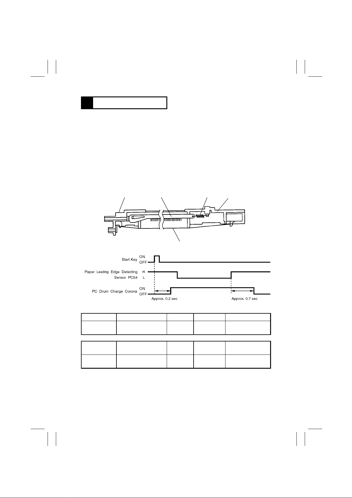
8 IMAGE ERAS E LAMP
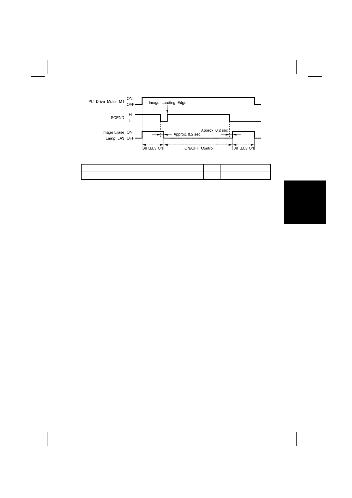
To prevent a b lack band fro m occ urring across both the leading and trailing edges, and
along the front and rear edges, of the electrostatic latent i m age, 31 LEDs of the Im age
Erase Lamp are turned ON before development takes place, thereby reducing to a minimum the unnecessary potential on the surface of t he PC Drum. Because of the light path
involved, this copier has the edge erasing cycle between drum chargi ng and exposure.
PC Drum Charge Corona
Image Erase Lamp LA3
Exposure
1139M031AA
The position of the Image Eras e Lamp can be adjusted using the adjusting screw on the
front of the copier.
Copier F r ont Frame
Copier Rear
Frame
Compression
Spring
Image Erase Lamp
1139M032AA
Image Erase La mp
Adjusting Screw
M-17
Page 21
FrameMaker Ver.5.5(PC) EP1054/EP1085/EP2030 GENERAL, MECHANICAL/ELECTRICAL
98.04.24
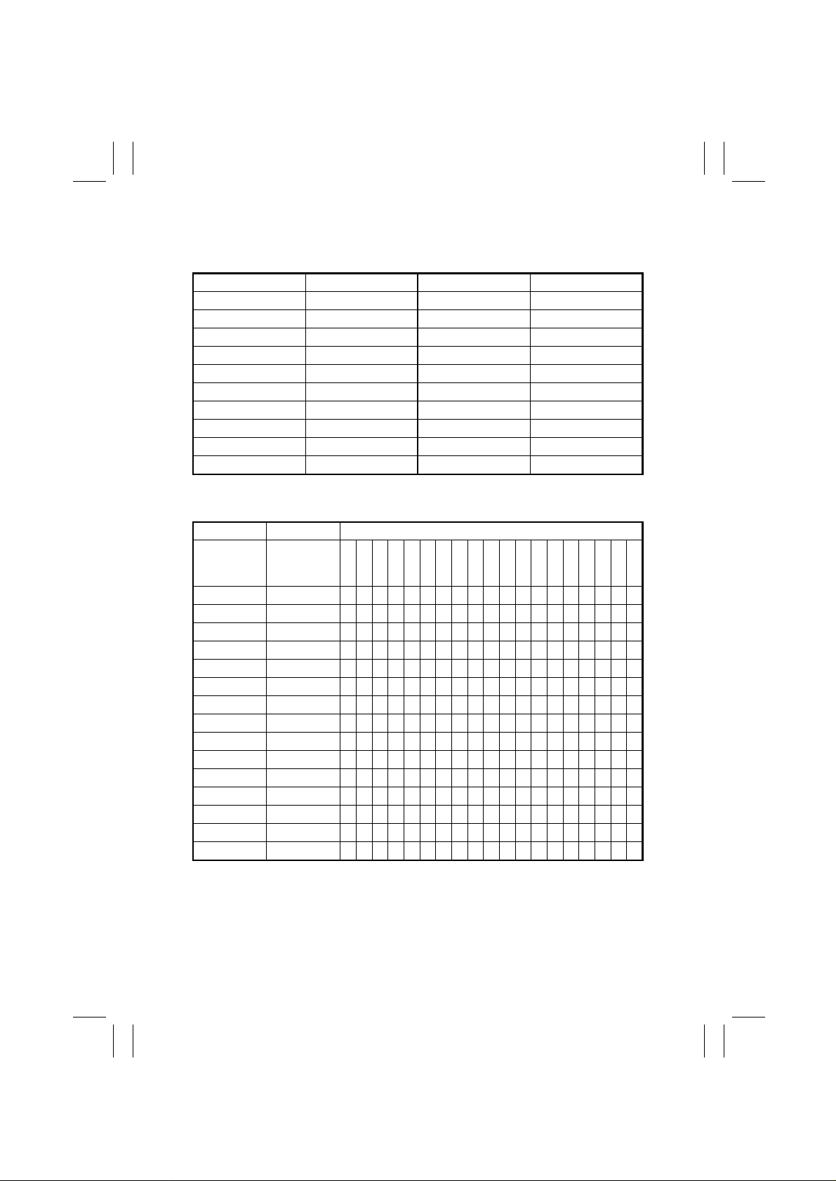
The 31 LEDs of the Image Erase Lamp are grouped as shown below. The table at the bot tom of this pag e sho ws wh ich LE Ds turn ON and OFF f o r dif f ere nt paper s iz es an d dif f e rent
zoom r atio s.
LED Group No. LED No. LED Group No. LED No.
00 LED 1 10 LED 23
01 LED 2 to 6 11 LED 24
02 LED 7 to 11 12 LED 25
03 LED 12 to 16 13 LED 26
04 LED 17 14 LED 27
05 LED 18 15 LED 28
06 LED 19 16 LED 29
07 LED 20 17 LED 30
08 LED 21 18 LED 31
09 LED 22
The smaller the number , the nearer the LED i s to the front side of the copier.
✽
LED ON/OFF Pattern
Zoom Ratio Paper Width LED Group No.
From - To
Less Than
(%)
50~53 to 152
53~57 152 to 163
57~61 163 to 173
61~64 173 to 183
64~67 183 to 192
67~70 192 to 201
70~74 201 to 212
74~78 212 to 223
78~82 223 to 235
82~86 235 to 247
86~90 247 to 259
90~93 259 to 270
93~96 270 to 281
96~99 281 to 291
99~ 291 to
: ON;
–
❍
Max. width (291 mm or more) applies to manu al bypass copying in which the copier is
✽
unable to detect paper width.
: OFF
From - To
Less Than
(mm)
00 01 02 03 04 05 06 07 08 09 10 11 12 13 14 15 16 17 18
–––
❍
––––
❍
–––––
❍
––––––
❍
–––––––
❍
––––––––
❍
–––––––––
❍
––––––––––
❍
–––––––––––
❍
––––––––––––
❍
–––––––––––––
❍
––––––––––––––
❍
–––––––––––––––
❍
––––––––––––––––
❍
–––––––––––––––––
❍
❍❍❍❍❍❍❍❍❍❍❍❍❍❍❍
❍❍❍❍❍❍❍❍❍❍❍❍❍❍
❍❍❍❍❍❍❍❍❍❍❍❍❍
❍❍❍❍❍❍❍❍❍❍❍❍
❍❍❍❍❍❍❍❍❍❍❍
❍❍❍❍❍❍❍❍❍❍
❍❍❍❍❍❍❍❍❍
❍❍❍❍❍❍❍❍
❍❍❍❍❍❍❍
❍❍❍❍❍❍
❍❍❍❍❍
❍❍❍❍
❍❍❍
❍❍
❍
M-18
Page 22
FrameMaker Ver.5.5(PC) EP1054/EP1085/EP2030 MECHANICAL/ELECTRICAL
98.04.24
Control Signal ON OFF WIRING DIAGRAM
LA3 PWB-A PJ16A-4A ~ 9A L H 1-G
1174T22MCB
M-19
Page 23
FrameMaker Ver.5.5(PC) EP1054/EP1085/EP2030 GENERAL, MECHANICAL/ELECTRICAL
98.04.24
1174SBM0900A
9 OPTICAL SECTION
As the Scanner is moved by the Scanner Motor, the light from the Exposure Lamp is
reflecte d off the original and gui ded through the four Mirrors onto the surface of the PC
Drum to form the electrostatic la tent image.
The image is enlarged or reduced as necessary by changing the position of the Lens and
4th Mirror and varying the angle of the 4th Mirror.
23 cpm Copier
•
4th Mirr o r
Mirror Motor M7
Scanner
Lens Motor M6
AE Sensor Board
(PWB-H)
Scanner Motor M5
15/18 cpm Copier
•
Scanner Motor M5
Scanner Shaft
Lens
2nd/3rd Mirrors
Carriage
1149M008AA
1139M033AA
M-20
Page 24
FrameMaker Ver.5.5(PC) EP1054/EP1085/EP2030 MECHANICAL/ELECTRICAL
98.04.24
1174SBM0901A
9-1. Exposure Lamp
An AC halogen lamp is used as the Exposure Lamp.
As the exposure le vel is adjust ed on the control panel, the duty ratio of the pulse of AVR
Remote from the Master Board changes t o i ncrease or decrease the Exposure Lamp v oltage, the r eby changing the image density.
In Photo mode , the v ol tage s are varied on a level 5V lo w er th an the ma n ual Ex posu re L amp
voltage s .
Manual EXP Setting9876 5 432✽1
Lamp Voltage
Diffe rence (V)
At Manual Exp osure Setting 1 only VG is reduced, thereby gi ving a lamp Voltage differ-
✽
ence equivalent to +8V.
–8 –4 –2 –1 Reference +1 +2 +4 +4
1174T13MCA
Control Signal ON OFF WIRING DIAGRAM
AVR Remote
Signal (LA1)
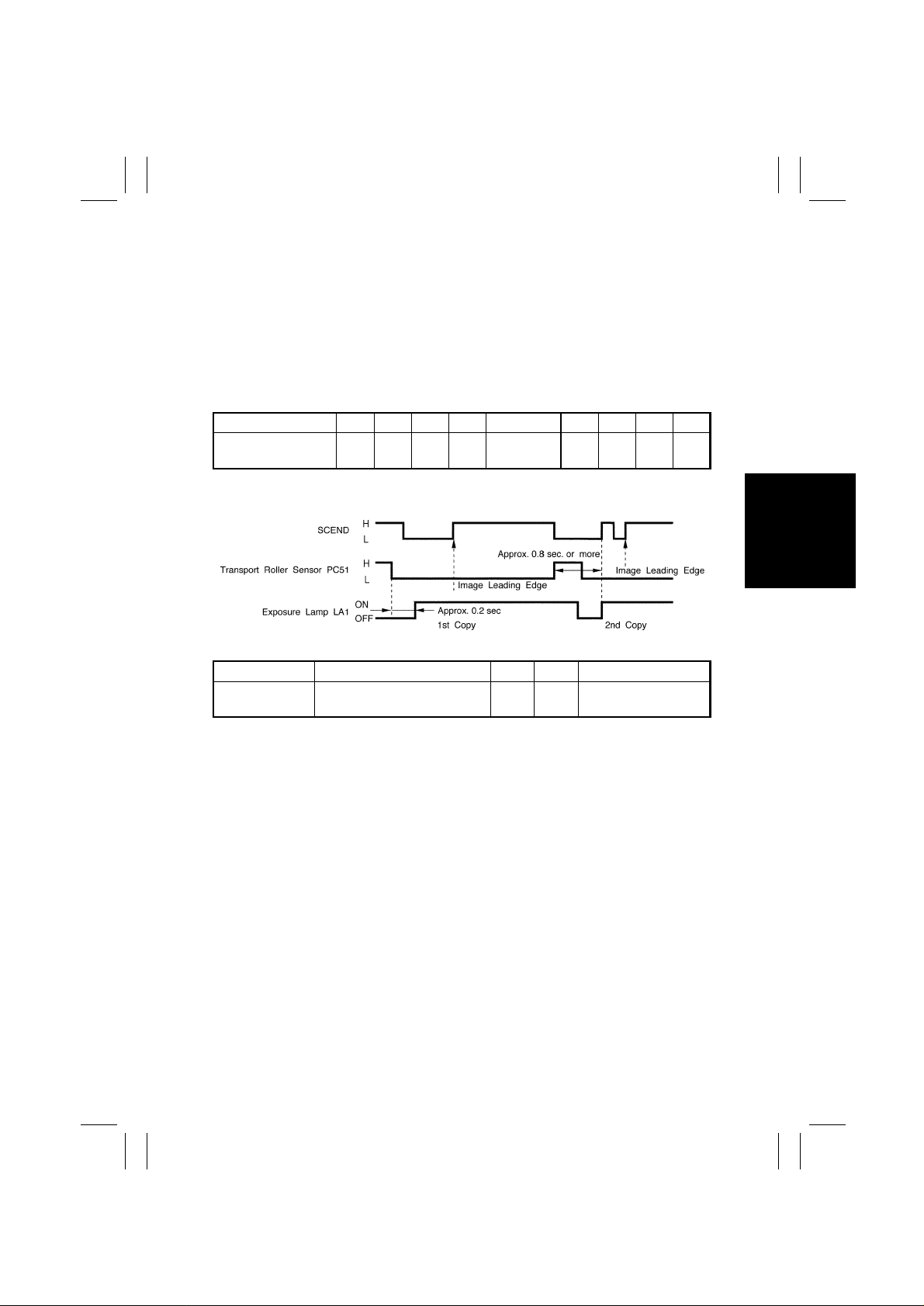
If reduction copie s are made using large size pa per, the trailing edge of the first copy
✽
moves past the Transport Roller Sensor after the SCEND signal for the second copy has
been generated. If the Exposure Lamp is turned ON for the sec ond copy at the same timing as the first one, therefore, the imag e for the second copy is produced on the trailing
edge of the fi rs t copy. T o p revent thi s f rom o ccurrin g, th e E xpos ure Lamp i s tu rned ON for
the second and subs equent copies whe n all of the foll owing conditions are met:
Approx. 0.8 sec. or more have elapsed after the first cop y deactiva ted the Transport
•
Roller Sensor.
The Transport Roller Sensor output i s HIGH.
•
The SCEND signal for the secon d copy is output.
•
PWB-A PJ14A- 3 L H 6-D
M-21
Page 25

FrameMaker Ver.5.5(PC) EP1054/EP1085/EP2030 GENERAL, MECHANICAL/ELECTRICAL
98.04.24
1174SBM0902A
9-2. AE Sensor
In the A u to Ex pos ure Mode , the A E Sens or on the AE Sen sor B oar d me asure s th e i nte nsit y
of the light reflected off the original, which results in the black/white ratio of a 210-mm-wide
area from the reference position of the origin al being measur ed. According to this measure ment, th e Exp osure La mp v o lta ge i s au to matica lly in creas ed or dec re ased so t ha t co pies of
consistent quality are produced.
The output from the AE Sensor is appl i ed to the Master Board which, in turn, varies the
duty rati o of the AVR Remote from it to vary accordingly the Exposure Lamp voltage.
Original Density (B/W Ratio) High Low
Intensity of Reflected Light Low High
AE Sensor Board Output High Low
AVR Duty Increased Decreased
Exposu r e La m p Voltage Increase d Decre ased
Control Signal ON OFF WIRING DIAGRAM
PWB-H
(AE Sensor)
AVR Remote
Signal (LA1)
PWB-A PJ9A-3 L H 4-F
PWB-A PJ14A- 3 L H 6-D
M-22
Page 26

FrameMaker Ver.5.5(PC) EP1054/EP1085/EP2030 MECHANICAL/ELECTRICAL
98.04.24
1174SBM0903A
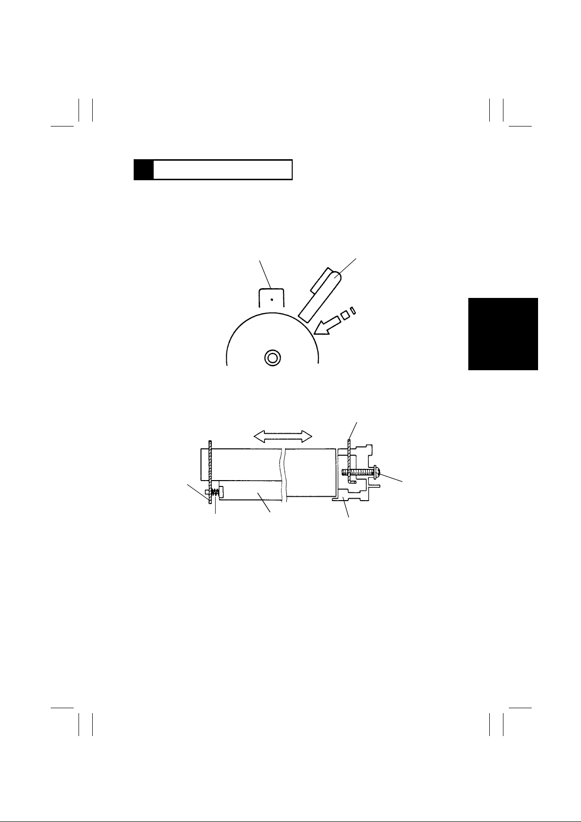
9-3. Lamp Reflectors
The Main Reflector ensures that light from the Exposure Lamp exposes all areas of the
original. Th e Auxiliary Ref lect or r efl ects l ight o nt o t he are as that the Ex posu re Lamp cann ot
illuminate when an original that does not lie flat on the Original Glass (such as a book) is
being used. This reduces shadows which would otherwise be transferred to the co py.
The Main Reflector is of aluminum, while the Auxiliary Reflector is aluminum to which film
has been deposi ted. The same fi lm as that used on th e A uxiliary Refl ector is affix e d to both
ends of the frame to compensate for the redu ced intensity of li ght around both ends of the
Exposure Lamp.
Auxiliary Reflector
Main Reflector
Exposure Lamp LA1
1151M021AA
1174SBM0904A
9-4. Aperture Plates
Four Aperture Plates are moved to the right or left to ens ure ev en l i ght distribut i on.
M-23
Aperture
1151M020AA
Page 27

FrameMaker Ver.5.5(PC) EP1054/EP1085/EP2030 GENERAL, MECHANICAL/ELECTRICAL
98.04.24
1174SBM0905A
9-5. Scanner and 2nd/3rd Mirror Carriage Movement
The Scanner and 2nd/3rd Mirrors Carriage are moved by the Scanner Drive Cable fitted in
the rear side of the copier. The Cable is driven by the Scanner Motor.
Both the Scanner and 2nd/3rd Mirrors Carriage slide along th e Scanner Shaft at the rear
side. At the front side, there is a Slide Bushing attached to the underside of each of the
bodies and th at Bushing slides over the Slid e R ail. The speed of the Scanner and 2nd/3rd
Mirrors Carriage varies with different zoom rati os.
The Scanner Reference Position Sensor detects the home position of the Scanner and
2nd/3rd Mirr ors Carriag e . If the y ar e not a t th e home po si tio n whe n t he co pier is tu rned ON,
the Scanner Motor is energized to move them to the home position.
23 cpm Copier
•
Scanner
Slide Rail
2nd/3rd Mirrors
Carriage
15/18 cpm Copier
•
Scanner Shaft
Scanner Drive Cable
Scanner Motor M5
Scanner Motor M5
Scanner
Reference
Position
Sensor PC81
1149M009AA
1151M022YA
M-24
Page 28

FrameMaker Ver.5.5(PC) EP1054/EP1085/EP2030 MECHANICAL/ELECTRICAL
98.04.24
The Scanner starts the scan motion as a Scan signal is output from the Master Board. At
the start of a scan motion and other heavy load conditions, the Scanner Motor requires a
large amount of current. The Current 1 or 2 signal from the Motor Drive Board is selected
accordingly to vary the amount of current supplied to the Scanner Motor.
The Current signal selection timing is control led by software.
✽
Current 1 H H L
Current 2 H L H
Operation
On receiving the Scan signal, the Motor Drive Board applies motor drive pulses, which are
out-of-phas e wit h each other, to the Scanner Motor . Th e mot or spee d is varied by changi ng
the width of the pulses applied to the Scanner Motor.
M5
Scan Signal
M5
Current
Switching
Signal 1
M5
Current
Switching
Signal 2
When the scan
speed reaches a
given level.
Control Signal Energized Deenergized WIRING DIAGRAM
PWB-F (23 cpm Copier)
PWB-E (15/18 cpm
Copier)
PWB-F (23 cpm Copier)
PWB-E (15/18 cpm
Copier)
PWB-F (23 cpm Copier)
PWB-E (15/18 cpm
Copier)
At scan start and during scan deceleration.
LH
LH
LH
At return start and
during return motion.
8-D/8-H
Control Signal Blocked Unblocked WIRING DIAGRAM
PC81 PWB-A PJ17A-7B L H 11-A
M-25
Page 29

FrameMaker Ver.5.5(PC) EP1054/EP1085/EP2030 GENERAL, MECHANICAL/ELECTRICAL
98.04.24
1174SBM0906A
9-6. 4th Mirror Mo vement
The 4th Mirror is moved to vary the conj ugat e dist ance for a particular zo om ra ti o by drivin g
the rack -and-pinion gears at the front and rear ends of the mirror using the Mirror Motor
(stepping motor). The Levers of the Holder t o w hi ch the Mirror is mounte d slide along a
tilted r ail to chang e t he Mirro r angl e. Thi s ensur es that the li ght stri ke s th e sur face of th e PC
Drum in the direction of the normal, thereby preventing resolut i on from being degraded.
The Mirror Reference P osition Sens or i s used to control th e position of the 4th Mi rror. It
ensures that the Mirror is located at the home position when the copier is turned ON.
Mirror Reference
Position Sensor (PC86)
Levers
Mirror
Drive Shaft4th Mirror
Motor
M7
Lever
Tilt Adjusting Screw
1139M038AA
1139M037AA
Control Signal Energized Deenergized WIRING DIAGRAM
M7 PWB-A PJ16A - 2B L H 8-B/8-F
Control Signal Blocked Unblocked WIRING DIAGRAM
PC86 PWB-A PJ22A-5 L H 12-A
M-26
Page 30

FrameMaker Ver.5.5(PC) EP1054/EP1085/EP2030 MECHANICAL/ELECTRICAL
98.04.24
1174SBM0907A
9-7. Lens Movement
The Lens is mo ved by the Lens Drive Cable whi ch is driven by the Lens Motor (stepping
motor). The motor drive pulses sent from the Motor Drive Board drive the Lens Motor to
move the Lens a given di stance, corresponding to the zoom ratio , from the reference position determined by the Lens Reference Position Sensor.
There is a fixed-type Lens Aperture Cover provided at the rear of the Lens (on the 4th Mirror end). It limits the amount of li ght striking the surface of the PC Drum.
Lens Reference Position Sensor PC 90
Lens Base Bra cket
Shaft
Lens
Spring
Lens Drive Cable
Lens Motor M6
Lens Aperture Cover
Lens
Lens Aperture Cover
Cam
1151M023AA
1149M010AA
Control Signal Energized Deenergized WIRING DIAGRAM
M6 PWB-A PJ16A - 1B L H 8-B/8-F
Control Signal Blocked Unblocked WIRING DIAGRAM
PC90 PWB-A PJ22A-8 L H 12-B
M-27
Page 31

FrameMaker Ver.5.5(PC) EP1054/EP1085/EP2030 GENERAL, MECHANICAL/ELECTRICAL
98.04.24
1174SBM1000A
10
ORIGINAL SIZE DETECTING S ENSORS (23 cpm COP IER ONLY)
The four sensors fixed in the optical section receive the light reflected off the original t o
determine the size of the original in the Auto Paper and Auto Size mode. (The i m age density of the origi nal, or OD, that can b e detected is 0.6 or l ess.)
1174SBM1001A
10-1. Original Size Detecting Sensors
Original Size Detecting
Sensor CD1 PC11 4
Original Size Detecting
Sensor CD2 PC116
Size Reset Switch
S108
1174SBM1002A
Original Size Detecting
Board UN2
Original Cover Detecting
Sensor PC111
Original Size Detecting
Sensor FD3 PC115
Original Size Detecting
Sensor FD2 PC113
1174M009AA
10-2. Original Size Detecting Operation
Each photo receiver of the original size detecting sens ors responds to reflected light of a
given intensity with reference to the i ntensity of the light emitted by each LED. This allows
the Original Size Detecting Board to determine whet her or not there is an ori ginal within a
set distanc e.
Photo Receiver
Original
Original Glass
Set Distance
LED
1136M020AA
M-28
Page 32

FrameMaker Ver.5.5(PC) EP1054/EP1085/EP2030 MECHANICAL/ELECTRICAL
98.04.24
1174SBM1003A
10-3. Sensor Locations
The number and lo cation of the Original Size Detecting Sensors vary depending on the
•
marketing area as shown below.
Sensors
Areas
Metric Areas
Inch Areas
Mixed inc h/ m etric Are as
U.S.A and Canada Areas
: Standard●: Optional
❍
NOTE
If the optional sensors are installed, set Jumper Connector JP2 on the Original Size Detect ing Board as illustrated below and run the F7 operation.
CD1
(PC114)
CD2
(PC116)
FD2
(PC113)
FD3
(PC115)
❍●❍●
❍●❍●
❍❍❍❍
●●●●
Width (Metric)
A5L
B5L
A4L
B4L, B5C
A3L, A4C
Length (Metric)
Length (Inch)
CD1
CD2
LED1 LED2
Letter C
Letter L
FD2 FD3
B5C A4C,
A5L
Original Size Detecting Board UN2
Legal
FLS
B5L A4L B4L A3L
CN1
JP1
JP2
CD2 and FD3
Position
of JP2
are mounted
CN4
CN3
CN2
11”×17”
Width (Inch)
L: Lengthwise
C: Crosswise
CD2 and FD3
are not mounted
Invoice
Legal,
Letter L
Letter C,
11”×17”
M-29
1174M012AB
Page 33

FrameMaker Ver.5.5(PC) EP1054/EP1085/EP2030 GENERAL, MECHANICAL/ELECTRICAL
98.04.24
1174SBM1004A
10-4. Size Detection
The Original Size Detecting Board reads the output data provided by the original size
•
detecting sensors. By comparing the data from each sensor with the threshold level, it
determines whether there is an original placed on the Orig i nal Glass. The Origi nal Size
Detecting Board then determines the size of the original according to the combination of
the data.
Metric Area
FD2 FD3 CD1 CD2
Original Size
A3L A3L (A3L)
B4L B4L (B4L)
A4L A4L (A4L)
A5L A5L (A5L)
A4C A4C (A4C)
Letter L:
8-1/2”×11”
11”×17” 11”×17” (A3L)
Legal:
8-1/2”×14”
FLS:
8-1/2”×13”
Letter C :
11”×8-1/2”
No Original A5L
Inch Area
Original Size
11”×17” 11”×17” (11”×17”)
Legal:
8-1/2”×14”
Letter L:
8-1/2”×11”
Letter C :
11”×8-1/2”
FLS:
8-1/2”×13”
Invoice:
5-1/2”×8-1/2”
No Original Invoice
: Original Present
✽❍
If no optional sensors are mounted, data is processed as i ndicated in ( ) and the original
✽
sizes determined by the Size Detecting Board are as indicated in ( ).
The Original Size Detecting Board does not use the d ata provided by LED2 of Original
✽
Size Detecting Sensor CD2 f or the determination of the original size.
Any non-standard size is rounded off to the n earest standard size.
✽
When all sensors detect no original , the Original Siz e Detecting Board determines that
✽
A5L or Invoice size is present.
Size Determined
by UN2
Letter L (Letter L)
Legal (A4L)
FLS (A4L)
Letter C (A4C)
Size Determined
by UN2
Legal (Legal)
Letter L (Letter L)
Letter C (Letter C)
FLS (Legal)
Invoice
●
LED1 LED2 LED1 LED2 LED1 LED2 LED1
❍❍❍(❍)❍(●)❍❍❍(❍
❍❍❍(❍)❍(●)●❍●(●
❍❍●(●)●(●)●●●(●
●●●(●)●(●)●●●(●
●●●(●)●(●)❍❍❍(❍
❍●●(●)●(●)●●●(●
❍❍❍(❍)❍(●)❍❍●(❍
❍❍❍(●)❍(●)●●●(●
❍❍❍(●)●(●)●●●(●
●●●(●)●(●)❍❍●(❍
●●●(●)●(●)●●●(●
FD2 FD3 CD1
LED1 LED2 LED1 LED2 LED1 LED2
❍❍❍
❍❍❍
❍●●
●●●
❍❍❍
●●●
●●●
: Original No t Present
(❍)❍(❍)
(❍)❍(❍)
(●)●(●)
(●)●(●)
(❍)●(❍)
(●)●(●)
(●)●(●)
❍❍
●●
●●
❍❍
●●
●●
●●
)
)
)
)
)
)
)
)
)
)
)
M-30
Page 34

FrameMaker Ver.5.5(PC) EP1054/EP1085/EP2030 MECHANICAL/ELECTRICAL
98.04.24
1174SBM1005A
10-5. Original Size Detection Timing
Master CPU on the Master Board affirms and resets t he readings of the original size at the
followin g timi ngs.
Takes size readings : When the Original Cover is r aised to an angle of 15° or more (Origi-
•
nal Cover Detecting Sensor is deactivated).
Affirms size readings: When the Original C over is lo wered to an angle of 15° or less
•
(Original Cover Detecti ng Sen s or is just acti v a te d); or, when the Start key is p ress ed wit h
the Original Cover Detecting Sensor in the deactivated state.
Resets size readings: When the Original Cover is raised (Size Reset Switch is deactu-
•
ated).
M-31
Page 35

FrameMaker Ver.5.5(PC) EP1054/EP1085/EP2030 GENERAL, MECHANICAL/ELECTRICAL
98.04.24
1174SBM1006A
10-6. Original Cover Angle Detection (23 cpm Copier Only)
The Original Cover De tecting Sensor detects the angle of the Ori gi nal Cover as it is raised.
The following control is provided.
Original Cover raise d to an angle of 15° or more:
The size of the original is read by the Original Size Detecting Sensors.
Original Cover raised to an angle of less than 15 °:
When the Origin al Co v e r Det ect ing Senso r is act iv at ed , the origina l siz e da ta is lat ched and
Original Size Detecting Board UN2 transmits the size data to the Master Board. As soon as
the Size Reset Switch is turned ON, the size data is validated and the paper size is shown
on the control panel.
The paper size selected is reset when the Size Res e t Switch is turned OFF.
Original Cover Detecting
Sensor PC111
Size Reset
Switch S108
Magnet
1139M093AA
Control Signal Blocked Unblocked WIRING DIAGRAM
PC111 PWB-A PJ18A-2 L H 12-B
Control Signal ON OF F WIRING DIAGRAM
S108 PWB-A PJ23A-11B L H 6-C
M-32
Page 36

FrameMaker Ver.5.5(PC) EP1054/EP1085/EP2030 MECHANICAL/ELECTRICAL
98.04.24
1174SBM1100A
11 DEVELOPMENT
The Developing Unit built into the Imaging Unit performs the following functions:
Mixes the t oner and carrier well to ensure that a suffici ent amount of toner is positively
•
charged.
Detects the tone r-to-carrier ratio of the developer by means of the ATDC Sensor and
•
replenishes the supply of toner as necessary.
Detects a toner em pty condition by means of the ATDC Sensor.
•
Ensures that a proper amount of toner is attracted to the PC Drum by means of its
•
Sleeve/Magnet Roller, Developing Bias, and Doctor Blade.
PC Drum
Devel oper Mixing Screw
Doctor Blade
M-33
1139M015AA
ATDC Sensor (UN3)Sleeve/Magnet Roller Bucket Roller
Page 37

FrameMaker Ver.5.5(PC) EP1054/EP1085/EP2030 GENERAL, MECHANICAL/ELECTRICAL
98.04.24
1174SBM1101A
11-1. ATDC Sensor
The ATDC Sensor instal l ed on the underside of the Developer Mi xing Chamber det ects the
varying ton er-to- carrie r r ati o of t he devel oper w hi ch fl ow s o ver it in th e Ch amber. The copier
CPU compares the detected ratio with the ratio set by the ATDC Detection Level Mode
(Tech. Rep. Choice C-90) to control toner r epl enishment.
Set T/C (%) ATDC Output Voltage (V)
6.0 2.5 (Standard)
Toner is replenished for 5 seconds (the Toner Bottle is t urned one turn, which is equivalent
to a run of 2 copy cyc l es) for each Toner Replenishing signal.
If the toner-to-carrier ratio becomes lower than 3.5% in a ton er-empty condition, the copier
inhibits the initiation of a new copy cycle (this feature can be enabled or disabled by a Tech.
Rep. Choice mode). When a ratio of 4% or more is recovered as a result of Auxiliary Toner
Replenishi ng, the copier permits the initiation of a new copy cycle.
If the Front Door is swung open and closed with a T/C ratio of less than 4%, t he copier initiates an Auxiliary Toner Replenishing sequence. (It stops the sequence as soon as a T/ C
ratio of 4.5% is reached.)
ATDC Sensor Automatic Adjustment
An automatic adjustment of the ATDC Sensor is made in the F8 Test Mode operation and
when a new Im agi ng Unit is instal led in the copier.
When a New Imag ing Unit is Installed in the Copier:
✽
Follo wing th e ex ec ution of the starter setup mod e upon pow er-up , the copier CPU read s the
output value of the ATDC Sensor and estab l ishes the reading as the reference value.
When F8 is Run after St arter Has Been Changed:
✽
Follo wi ng t he e xecution of the starter setup mode upo n pr essi ng o f the St art Key, the copier
CPU reads the out put value of the ATDC Sensor and establishes the reading as the reference value.
NOTE
If an F8 operation is run at a time w hen the starter has not been changed, it ca n result in a
wrong T/C reference val ue being set by the copier. Av oid casual use of F8.
If the setti ng value has been cleared because of the R AM Board being replaced, however,
enter the ATDC control value before the repla cement using the Zoom Up/Down Keys in the
F8 operation (without pressing the Start Key).
M-34
Page 38

FrameMaker Ver.5.5(PC) EP1054/EP1085/EP2030 MECHANICAL/ELECTRICAL
98.04.24
Toner Empty Detection
The copier has no toner empty detect ing sensor and, instead, the ATDC Sensor performs
that functi on. The ATDC Sensor checks the toner-to-carrier ratio and, if it reads a T/C ratio
lower than the set level for 37 copies and, f urther, if it next reads a ratio 1% lower than the
setting , this is a toner-emp ty condition. The toner-empty cond ition is canceled after detection under any of the following conditions when the Fr ont Door is sw ung open and closed:
T/C is 4% or more: The toner-empty condit i on is canceled.
•
T/C is less than 4%: The copier initiates an Auxiliary Toner Replenishing sequence and
•
cancels the toner-empty condition as soon as T/C reaches 4.5%.
Standard
Control Signal Set T/C
UN3 PWB-A PJ10A-3 6.0% 2.5 2-H
Output
Voltage
WIRING DIAGRAM
M-35
Page 39

FrameMaker Ver.5.5(PC) EP1054/EP1085/EP2030 GENERAL, MECHANICAL/ELECTRICAL
98.04.24
1174SBM1102A
11-2. Magnet Roller
The Magnet Roller of the Sleeve/Magnet Rol ler of this copier has the following magnetic
characte rist ic s. P art of pol e S2 b efore the princ ipa l N1 pol e (i.e., the area mark e d as S2b in
the Fig. below) provides a very weak magnetic force. If developer i s compacted and clogs
at the Doctor Blade and, as a result, part of the surface of the Sleeve/M agnet Roller is not
covered with developer, the nearby developer around S2b goes to those uncovered areas
because of it s weak magnetic force. This helps prevent blank lines from occurring on the
copy .
The Sleeve Roller, onto which developer is attracted by the magnetic fields of force set up
by the poles of the Magnet Roller, turns to convey the developer toward the po i nt of development.This al so means that de veloper fresh from the Developer Mixing Cha m ber is
alwa ys brought to the point of development.
As noted ea rlie r , t he Ima ging Uni t i nte gr at es t he Developing U nit w ith t he PC Dr um in to one
body. Because of that, it is impossible to move the Developing Unit against the PC Drum,
thereb y providing a certain d istance between the PC Drum and Sleeve/Magnet R oller . The
Sleeve/Magnet Roll er has therefore been made mov able: the Bushing is pressed by compression springs thereby pressing the Positioning Collars on both ends of the Sleeve/Magnet Roller ag ai nst the PC Drum. This ensures a given distance between the PC Drum and
the Sleeve/Magnet Roller.
Magnetic Pole Positioning
Pole Having Wea k
Magnetic Force
Movable Bushi ng
Compression Spring
Fixed Bushing
M-36
PC Drum
1139M016AA
1139M017AA
Page 40

FrameMaker Ver.5.5(PC) EP1054/EP1085/EP2030 MECHANICAL/ELECTRICAL
98.04.24
1174SBM1103A
11-3. Developing Bias
A negativ e v ol tag e (Vb = De v e lopin g Bi as vo lt age) is a pplie d to th e Sl ee ve Roller to prevent
a foggy background on the cop y. The amount of toner attracted onto the surface of the PC
Drum depends on how much lower the PC Drum surface potential (Vi) is than Vb (i.e., the
potential difference).
When the potential difference is large, a greater amount of toner is attracted.
•
When the potenti al difference is small, a small er amount of toner is attracted.
•
Because the Sl eeve/Magnet Roller of this copier is mov able, a flat s pri ng is used as the
Bias Terminal which fol l ows the movement of the Sleeve/Magnet Roller.
Sleeve/Magnet R oller
Bias Terminal
1139M018AA
1151T01MCA
Control Signal ON OFF WIRING DIAGRAM
Developing Bias PWB-A PJ11A-8A L H 2-H
M-37
Page 41

FrameMaker Ver.5.5(PC) EP1054/EP1085/EP2030 GENERAL, MECHANICAL/ELECTRICAL
98.04.24
1174SBM1104A
11-4. Doctor Blade
The Doctor Bl ade installed over the Sleeve/Magnet Roller regulates the height of the developer brush on the surface of the Sleeve Roller. The Blade is perpendicular to t he di rection
of movement of the Sleeve/Magnet R ol ler to minimiz e variations in the distance betw een
the Doctor Bl ade and Sleeve/Magnet Roller as the Sleeve/Magnet Roller moves .
Doctor Blade
Direction of Magnet
Roller Movement
Sleeve/Magnet Roller
1139M019AA
1174SBM1105A
11-5. Sleeve/Magnet Roller Lower Filter
Except the U.S.A., Canada, and Europe
✽
There is a slit provided under t he Sleeve/Magnet Roller to collect insu fficiently charged
toner in the grounded Toner Antispill Trap. This effectively prevents the toner from spilling
onto the mechanisms inside the co pier.
Sleeve/Magnet Roller
Slit
1139M020AA
M-38
Page 42

FrameMaker Ver.5.5(PC) EP1054/EP1085/EP2030 MECHANICAL/ELECTRICAL
98.04.24
1174SBM1200A
12 TONER HOPPER
1174SBM1201A
12-1. Toner Hopper Locking/Un locking
The Toner Hopper is not inte grated into the Imaging Unit; instead, it is secured to the
copier. To replace an empty Toner Bottle, the user first nee ds to swing the Toner Bottle
Holder out 40° to th e f ron t. T he Ho lder pi v ots abo ut th e Toner Suppl y Port as it is swung out
or in, which effectively prevents toner from spilling when the Holder is swung out or in.
Copier Frame
Lock
Toner Replenishing
Motor M8
Toner Supply Port
1139M024AA
1174SBM1202A
40°
Toner B ottle
Toner Bottle Holder
12-2. Toner Replenishing
Drive from the Toner Replenishing Motor is tr ansmitted via the mot or shaft to the Bottle
•
Cap Claw, which turns the Toner Bottle. As the Toner Bottle is fitted to the Coupling, both
turn together during t oner replenishing.
A Metering Chamber pr ovided at the toner supply port of the Coupling regulates the
•
amount of toner that falls through the port.
There is a supply port for the exclusive use of the starter. The starter does n ot pass
•
through the Metering C hamber, which means that it takes a shorter time to loa d the
starter.
Starter
Supply Port
Metering Chamber
Coupling
Opening
1139M025AA
Bottle Cap Cla w
Toner Replenishing Motor M8
1151M018YA
M-39
Page 43

FrameMaker Ver.5.5(PC) EP1054/EP1085/EP2030 GENERAL, MECHANICAL/ELECTRICAL
98.04.24
1174SBM1203A
12-3. Shutter
The connection between the Toner Hopper and I maging Unit is provided with a Shutter
which prevents toner from spilling when the Imaging Unit is slid out of the copier.
Imaging Unit Out of Copier Imaging Unit i n Position in Copier
Shutter
1139M026AA
1139M027AA
Imaging Unit
1174SBM1204A
12-4. Toner Hopper Home P osition Detection
The Coupling is fitted with a Home Position Plate which is detect ed by the Toner Hopper
Home Position Sens or. This ensures that the Toner Bottle is located so that it s opening is
positione d on top whenever the Toner Replenishing Motor is deenergized.
Toner Replenishing Motor M8
Home Position Plate
1151M019AA
Toner Hopper Home
Position Sensor PC 112
M-40
Page 44

FrameMaker Ver.5.5(PC) EP1054/EP1085/EP2030 MECHANICAL/ELECTRICAL
98.04.24
1174SBM1205A
12-5. Toner Bottle Vibration
When the indentations at three places on the left-hand end ( as viewed when the Toner Bottle is in position) of the Toner Bottle move past the protrusion in the Toner Bottle Holder, the
Toner Bottle is vibrated to prevent some of the toner from remaining unconsumed in the
Bottle.
Toner Bottle
Indentations
Protrusion
1139M029AA
Toner Bottle Holder
M-41
Page 45

FrameMaker Ver.5.5(PC) EP1054/EP1085/EP2030 GENERAL, MECHANICAL/ELECTRICAL
98.04.24
1174SBM1206A
12-6. Toner Replenishing Control
1. The ATDC Sensor installed in the Imaging Unit reads the toner-to-carrier rati o of the
developer in the Developer Mixing Chamber for each copy cycle.
2. It samples the ratio 16 times and compares each with the preset level.
3. If eight or more readings out of the total 16 are lower than the preset level, a Toner
Replenishi ng signal is output.
4. The Toner Replenishing Motor is turned one complete turn for each Toner Replenishing
signal (which is equivale nt to a supply of 0.3 to 0.6 g toner).
The readings taken while the Toner Replenishing Motor is turning (it takes 5 seconds for
✽
the Toner Replenishing Motor to turn one complete turn) are igno red. This mean s that, in
a multi-copy cycle, the ATDC Sensor may take readings as the next copy cycle is started
while the Toner Replenishi ng Motor is turning; but, those readings are ignored.
Control Signal Energiz ed Deenergized WIRING DIAGRAM
M8 PWB-A PJ5A-6 H L 2-D
Control Signal Blocked Unblocked WIRING DIAGRAM
PC112 PWB-A PJ17A-2B L H 2-D
Control Signal Set T/C
UN3 PWB-A PJ10A-3 6.0% 2.5 2-H
Reference
Voltage
WIRING DIAGRAM
M-42
Page 46

FrameMaker Ver.5.5(PC) EP1054/EP1085/EP2030 MECHANICAL/ELECTRICAL
98.04.24
1174SBM1300A
PAPER T AKE-UP/FEED SECTION (2ND DRAWER: 23 cpm COPIER ONLY)
13
The copier is equipped with two Paper Drawers, 1st and 2nd, that can be slid out to the
front of th e copier. Each can hold up to 250 sheets of paper.
The 1st Drawer is a universal paper size type, whi le the 2nd Drawer is a fix ed paper size
type.
Paper Take-up
Solenoids (SL2, SL3)
1st Drawer Set
Detecting Switch
S65
Marketing
Area Switch
S66
Pape r Size
Detecting Switches
(S61 ~ S64)
2nd Draw er Set
Sensor PC69
Paper Sizes That Can be Loaded
Marketing
Area
Switch
S66
Inch
Inch
Areas
Metric
Paper
Take-Up Rolls
5.5” × 8.5”, 8.5” × 11”, 8.5” × 14”,
11” × 8.5”, 11” × 14”, 11” × 17”
A5L, A4L, A4 C, A3L
8” × 13”, 8.5” × 13” [G.LEGAL]
8-1/4” × 13”
Paper Take-Up Sensors (PC55, PC56)
Paper Empty Sensors (PC101, PC102)
1st Drawer
(Universal Paper Size)
2nd Drawer
(Fixed Paper Size)
1151M004YA
1st Drawer 2nd Drawer
8.5” × 11” [LETTER], 11” × 8.5”
[LETTER], 8. 5” × 13” [G.LEGAL],
8.5” × 14” [LEGAL],
11” × 17”, 5.5” × 8.5” [INVOICE],
8” × 10.5” [G.LETTER]
10.5” × 8” [G.LETTER], 8-1/4” × 13”,
10” × 14”, 11” × 14”, 210 × 280,
280 × 210, 216 × 297, 216 × 320,
220 × 280, 220 × 330, 280 × 420
M-43
Page 47

FrameMaker Ver.5.5(PC) EP1054/EP1085/EP2030 GENERAL, MECHANICAL/ELECTRICAL
98.04.24
Marketing
Area
Switch
1st Drawer 2nd Draw er
S66
Metric
Metric
Areas
Inch
Except Taiwan
✽
1174SBM1301A
A3L, B4L, A4L, A4C, A5L, B5C,
B5L (Taiwan Only), 8” × 13”,
8.5” × 13”✽, 8-1/4” × 13”
5.5” × 8.5” [INVOICE],
8.5” × 11” [LETTER]✽,
8.5” × 14” [LEGAL]✽, 11” × 17”
A3L, B4L, A4L, A 4C, A5L, 8” × 13”
8-1/4” × 13”, 10” × 8” [QUARTO],
210 × 280, 216 × 297, 297 × 216,
216 × 320, 220 × 280, 297 × 430
✽
13-1. Edge Guide and Trailing Edge Stop
1st Drawer
The 1st Drawer is a universal type allowing the user to slide freely the Edge Gui de and
Trailing Edge Stop to accommodate paper of different sizes.
The Edge Gu ide and Trailing Edg e S to p can be lo cked into po si tio n b y meshi ng t he no tche s
in the Lock Lever wi t h t h ose in the Drawe r.
Draw er Side
Lock Lever
Trailing Edge Stop
1139M053AA
1139M052AA
Edge Guide
1139M054AA
2nd Drawer
The 2nd Dr awer is a fixed paper size typ e, in which the Edge Guide and Trailing Edge Stop
are screwed into fi xed positions.
The Edge Guid e is provided wit h an Edge Pad (whi ch is Velcro) that prevents double feed
and ensures that the paper stack keeps its correct alignment with regard to the paper path
reference positio n.
M-44
Page 48

FrameMaker Ver.5.5(PC) EP1054/EP1085/EP2030 MECHANICAL/ELECTRICAL
98.04.24
1174SBM1302A
13-2. Drawer P ositioning
Each of the 1st and 2nd Drawers is positioned by fitting its Positioning Plat e on the paper
take-up end into the groove in the Drawer Frame. It is then secured in positi on by the magnet insta lled in t he Dr a we r Front Cov er on the paper tak e- up end . The tabs on both sid es at
the front of the Draw er ensure that the Drawer cl i cks into p osition. Any deviation in the
paper path reference position can be adjusted within ±2 mm by movin g the Fron t C over of
the Drawer to the front or rear.
Tab
Rear End
Positioning
Plate
Front End
1139M056AA
Position
Plate
1151M024AA
1139M057AA
1174SBM1303A
13-3. Paper Lifting Plate
The Paper Lifting Plate of each Drawer is raised at all times by two Paper Lifting Springs.
For the 2nd Drawer, the type and position of the Paper Lifting Springs must be changed
according to the paper size. (For details, see DIS/R EASSEMBLY, ADJUSTMENT.)
Paper Lifting Plate
Pape r Li fting Springs
M-45
1139M058AA
Page 49

FrameMaker Ver.5.5(PC) EP1054/EP1085/EP2030 GENERAL, MECHANICAL/ELECTRICAL
98.04.24
1174SBM1304A
13-4. Drawer-in-Position Detection
The copier detects that the Drawer is slid into position as follows.
1st Drawer
When the 1st Drawer is slid into the copier, the Drawer Fr ame presses the 1st Drawer Set
Detecting Switch installed on the back panel of the copier.
2nd Drawer
When the 2nd Drawer is slid into the copier, the Rib on the Drawer Frame blocks the 2nd
Drawer Set Sensor.
Paper Size
Detecting Switches
S61
S62S63
1st Drawer Set
Detecting Switches S65
1139M060AA
Drawer Frame
2nd Drawer Set Sensor PC69
<Control>
Control Signal ON OF F WIRING DIAGRAM
S65 PWB-A PJ15A-11 L H 15-B
Control Signal Blocked Unblocked WIRING DIAGRAM
PC69 PWB-A PJ2A-2 L H 17-A
1139M061AA
M-46
Page 50

FrameMaker Ver.5.5(PC) EP1054/EP1085/EP2030 MECHANICAL/ELECTRICAL
98.04.24
1174SBM1305A
13-5. Universal Tray (1st Drawer) Paper Size Detection
The length (feeding direction) and width (crosswise direction) of the paper are independently detec ted and the copier determines the paper size by combining the two separate
detections made.
On the bottom of the tray is a le v er fit ted to the Trailing Edge Stop and another lev er f itted to
the Edge Guide. These le vers actuat e and deactuate Paper Size Det ecting Switches to
allow the copier to determine a particular paper size.
The Marketing Area Switch is used t o set the type of paper to be used (inch or metric).
S62
Marketing Area
Switch S66
S61
S63
S64
Drawer Set Detecting
Switch S65
NOTE
The number and the installed position of
the Pap er Take-Up Roll s vary depe nding o n
the marketing areas: inch or metric. See
pp. M-43 and M-44 for the sizes of the
paper that can be taken up and f ed out of
the drawer.
1151M003AA
Paper Size Detecting Switches
Length (FD) Width (CD)
S61 S62 S63 S64
ON ON ON – 402.0~402.0 A3 11” × 17”
ON ON OFF
ON OFF OFF
OFF OFF OFF – 317.2~272.0 A4L Letter L
OFF OFF ON
OFF ON ON
OFF O N OFF
The 2nd Dra w e r acc epts only pa per of a fi x ed s iz e an d ha s no pa per si z e de te ctin g syst em.
(The paper size is input from the control panel using a Tech. Rep. Mode.)
OFF
ON 11” × 14”
OFF
ON 11” × 14”
OFF
ON Letter C
OFF
ON A4L Letter C
OFF
ON Letter L
Paper Length
402.0~349.2 B4
349.4~317.2 FLS
272.0~222.0 B5L
222.0~195.0
195.0~195.0 B5C
Inch/Metric Setting Switch S66
Metric Inch
8-1/2” × 14”
8-1/2” × 14”
Letter L
A5L Invoice L
Letter C
M-47
Page 51

FrameMaker Ver.5.5(PC) EP1054/EP1085/EP2030 GENERAL, MECHANICAL/ELECTRICAL
98.04.24
<Control>
Control Signal ON OF F WIRING DIAGRAM
S61 PWB-A PJ15A-1 L H 14-A
S62 PWB-A PJ15A-3 L H 14-A
S63 PWB-A PJ15A-6 L H 15-A
S64 PWB-A PJ15A-9 L H 15-A
S66 PWB-A PJ2A-4 L H 17-B
1174SBM1306A
13-6. Paper Empty Detection
When the Dr a we r runs ou t of p ape r, the Ac tuat or for the Paper Empty Sens or drops int o the
cutout in the Paper Lifting Plate. This activates the Paper Empty Sensor and the copier
detects that the Drawer has run out of paper.
As noted ea rlie r , t he Paper Lif tin g Pl ate is ra ised a t all t imes b y the Paper Lifting Springs. To
prevent the Actuator for the Paper Empty Sensor from being caught by the paper stack
when the Drawer is slid out of the copier, it is tilted slightly. This, however, results in the
operating stroke of the Actuator becoming small, which increases the possibility of the
Actuator activating the Sens or by the flexing of a sheet of paper a s it is ta ken up and fed in.
To prevent thi s false detection of a paper-empty condition, the paper empty detection is
enabled only when the P aper Take-Up Roll is in the retracted positio n.
Paper Empty Sensor (PC101, PC102)
1139M062AA
Actuator
<Control>
Control Signal Blocked Unblocked WIRING DIAGRAM
PC101 PWB-A PJ4A-6 L H 17-F
PC102 PWB-A PJ3A-4 L H 17-D
M-48
Page 52

FrameMaker Ver.5.5(PC) EP1054/EP1085/EP2030 MECHANICAL/ELECTRICAL
98.04.24
1174SBM1307A
13-7. Paper Separat ing Mechanism
Each Dra wer has Fingers that separate the top sheet of paper from the rest of the paper
stack at paper take-up. The Fingers are fi tted to the right front and rear corners of the
Drawer. When the Paper Take-Up Rol l starts turning to tak e up the top sheet of paper, its
turning f orce is di rectl y t r ansmit ted t o the to p she et of pa per as it is in dire ct con tact wit h the
Pape r Take-Up Roll. That force overcomes the block of the Fingers, causi ng the top sheet
of paper to ride over the Finge rs and be fed out of the Drawer into the copier.
As to the s econ d s hee t of pap er, the paper transport f orce obt ain ed t hro ugh fri cti on w it h the
top sheet of pa per is weak and does not al l ow the second sh eet of paper to ride over the
bloc k of the Fingers. Hence, the second sheet of paper remains stationary with the rest of
the paper s ta ck in t h e D rawe r.
When there are only two sheets of paper left in the Drawer, the bottom sheet can be fed
with the top one if the fricti on of the Paper Lifting Plate is weak. The F r iction Plate affixed to
the Paper Lifting Plate prevents this from happening.
Paper Take-Up Roll
Paper
Paper Lifting PlateFriction Plate
Separator Finger
1139M063AA
M-49
Page 53

FrameMaker Ver.5.5(PC) EP1054/EP1085/EP2030 GENERAL, MECHANICAL/ELECTRICAL
98.04.24
1174SBM1308A
13-8. Paper Take-Up Roll
Since the Paper Lifting Plate is raised at all times by the Paper Lifting Springs, paper is
wedged in the mec hanism when the Drawer is slid out of the copier if the Paper Take-Up
Roll is rou nd in s hape . So t he Take-Up Ro ll i s s emici rcula r a nd th e circ u lar part of th e Roll i s
positioned on top at times other than take-up. For convenience, we call this position of the
Paper Take-Up Roll the “retracted” position.
The Pap er Take-Up Roll is g rooved to k eep good friction e ven under hea vy l oadi ng. T he 1st
Draw er, which is a universal type to accommodate paper of di fferent sizes, is provided with
five (four in areas usi ng only inch paper) Paper Take-Up Rolls. T he 2nd Drawer accommodating paper of a fixed size only is equip ped with two Rolls whose positions must be
changed acc ording to the paper size. (F or the positions, see DIS/REASSEMBLY, ADJUSTMENT.)
The Paper Take-Up Roll is driven wh en the Paper Take-Up Solenoid is energized. The Roll
is turned one complete turn for each s i ngle sheet of paper.
The Paper Take-Up Sensor is used to detec t whether a sheet of paper has been properly
taken up or not .
Paper Take-Up Roll
Ratchet
1139M064AA
Paper Take-Up Sensor (PC55, PC56)
Actuator
Paper Take-Up Solenoid (SL2, SL3)
Ratchet
1151M025AA
Vertical Transport Roller
1139M066AA
M-50
Page 54

FrameMaker Ver.5.5(PC) EP1054/EP1085/EP2030 MECHANICAL/ELECTRICAL
98.04.24
1174T21MCA
Control Signal Energized Deenergized WIRING DIAGRAM
SL2 PWB-A PJ4A-9 L H 17-F
SL3 PWB-A PJ3A-2 L H 17-D
Control Signal Blocked Unblocked WIRING DIAGRAM
PC55 PWB-A PJ4A-2 H L 17-F
PC56 PWB-A PJ3A-7 H L 17-E
1174SBM1309A
13-9. Paper Take-Up Retry Control
To minimize the occurrence of paper misfeed due to a slippery Paper Take-Up Roll, the
Pape r Take-Up Sol enoid is energized a second time if a sheet of paper fails to reach the
Pape r Take-Up Sens or wit hi n T s ec. after th e s ole noid has b een deen ergi ze d. The sol enoi d
is energized this second time 0.5 sec. after the above-mentioned period of T sec. has
elapsed. (This is referred to as the paper take-up retry function.)
A misfeed res ults if the sh eet of pap er do es not reac h th e P a per Take-Up S ensor even af te r
three paper take-up sequences (i nitial take-up plus two retries).
Here is the control timing chart.
1174T15MCA
1st Drawer 2nd Drawer
T 1.3 sec. 1.6 sec.
M-51
Page 55

FrameMaker Ver.5.5(PC) EP1054/EP1085/EP2030 GENERAL, MECHANICAL/ELECTRICAL
98.04.24
1174SBM1310A
13-10.VERTICAL PAPER TRANSPORT
The sheet of paper taken up by the Paper Take-Up Roll from the Drawer is fed along the
Pape r Guide to the Vertical Transport Rollers. The paper fed by the Vertical Transport Rollers reache s t he Transport Roll ers and is then fed up to the Synchronizing Rollers. The
Transport Rollers are turned and stopped by the Paper Transport Clutch. The Transport
Roller Sensor i mmediately before the Transport Rollers detects a sheet of paper fed from
the Vertical Transport Section or Manual Bypass Table.
The Cov er for the Vertical Transport Section (i .e . , the S ide Door) can be open ed a nd cl ose d
for clearing misfeeds. The Side Door Dete ct i ng Sensor detects whether or not this Cover is
open.
<23 cpm Copier> <15/18 cpm Copier>
Transport
Rollers
Actuator
Transport Roller
Sensor PC51
<Control>
Transport
Rollers
Side Door
Detecting
Sensor PC57
Vertical
Transport
Rollers/Rolls.
1139M067AA
Actuator
Transport Roller
Sensor PC51
Side Door
Detecting
Sensor PC 5 7
Vertical
Transport
Rollers/Rolls.
1142M006AA
1174T16MCA
Control Signal Energized Deenergized WIRING DIAGRAM
CL2 PWB-A PJ5A-2A L H 4-B
Control Signal Blocked Unblocked WIRING DIAGRAM
PC54 PWB-A PJ17A-2A L H 4-D
M-52
Page 56

FrameMaker Ver.5.5(PC) EP1054/EP1085/EP2030 MECHANICAL/ELECTRICAL
98.04.24
1174SBM1400A
14 M ULTI BYPASS TABLE
The optional Mul ti Bypass Table permits the user to make multiple copies (up to 50) on
paper that cannot be fed automatically via any built-in paper drawer of the copier.
Standard on 23 cpm co pier, optional on 18 cpm copier and 15 cpm copier.
✽
Lever
Manual Feed
Paper Empty
Sensor
PC31
Paper Take-Up
Clutch CL51
Paper Take-Up Roll
Manual Fe ed Paper Take-Up Solenoi d
SL51
1139M087AA
M-53
Page 57

FrameMaker Ver.5.5(PC) EP1054/EP1085/EP2030 GENERAL, MECHANICAL/ELECTRICAL
98.04.24
1174SBM1401A
14-1. Paper Take-Up Mechanism
The Paper Take-Up Rolls are normally in their raised (retracted) position so that they will
not hamper proper loading of paper. When the Start Key is pressed, the Manual F eed
Pape r Take-Up Sol enoid is deenergized causing the Paper Take-Up Rolls to press the
paper stack downward and take up a sheet of paper.
Pape r Stoppers are provided that block the leading edge of the paper stack as it is loaded
on the Table, preventing any portion of the lea di n g edge of the paper from getting inside.
These Stoppers are unlocked at paper take-up, allo w ing paper into the copier.
Manual F eed Paper Take-Up Clutch controls the turni ng and stop of the P aper Take-Up
Rolls.
In Standby
At Take-Up
Lock Levers Lever
Paper Take-Up
Rolls
Pape r Stoppers
Rack Gear
1139M088AA
1139M089AA
Manual Feed
Paper Take-Up
Solenoid SL51
M-54
Page 58

FrameMaker Ver.5.5(PC) EP1054/EP1085/EP2030 MECHANICAL/ELECTRICAL
98.04.24
1174T18MCA
Control Signal Energized Deenergized WIRING DIAGRAM
CL51 PWB-A PJ5A-4B L H 17-H
SL51
DOWN
SL51
UP
1174SBM1402A
PWB-A PJ5A-2B L H
17-H
PWB-A PJ5A-3B L H
14-2. Paper Take-Up Retry Control
To minimize the occurrence of a paper misfeed due to a slippery Paper Take-Up Roll, the
Manual Feed Paper Take-Up Clut ch is kept deenergized for a giv en period of time before it
is energized again, if a sheet o f paper fails to reach the Transport Roller Sensor e ven after
the lapse of a g iv en p eriod of ti me aft er the c lutc h ha s first been energi z ed. (T his i s referred
to as the pap er take-up re try function.)
A misfeed results if the sheet of paper does not reach the Transport Roller Sensor even
after three paper take-up sequences (initial take-up plus two retries).
Here is the control timing chart.
1174T19MCA
M-55
Page 59

FrameMaker Ver.5.5(PC) EP1054/EP1085/EP2030 GENERAL, MECHANICAL/ELECTRICAL
98.04.24
1174SBM1403A
14-3. Paper Separat ing Mechanism
The paper separating mechanism ensures that only the top sheet of paper is fed in by separating the second sheet of paper from the top one. This is accomplished by th e Torque
Limiter fitted to the Separator Roll shaft which stops the Separator Roll when there is a
change in friction between the Feed and Separator Rolls.
1174SBM1404A
14-4. Paper Empty Detection
The Multi Byp ass Table is equi pped wi th a Man ual F e ed P a per Emp ty Sen sor wh ic h d etec ts
a sheet of paper at the manual bypass port.
Manual Feed
Pape r Empty Sensor
PC31
Paper Take-Up Roll
Pape r Stopper
Actuator
1139M092AA
Control Signal Blocked Unblocked WIRING DIAGRAM
PC31 PWB-A PJ5A-6B L H 17-H
M-56
Page 60

FrameMaker Ver.5.5(PC) EP1054/EP1085/EP2030 MECHANICAL/ELECTRICAL
98.04.24
1174SBM1500A
15 SYNCHRONIZING ROLLERS
The Synchroni zing Rollers, operating in phas e w ith the Scanner’s scan motion and paper
feed ing, synchr oniz e the lead ing edge of the cop y paper accur atel y with the leading edge of
the toner image on the PC Drum.
The Upper Synchronizing Roller is a metal roller covered with a polyvinyl chloride tubing,
while the Lower one is a rubber roller.
Synchronizing
Upper Synchronizing Roller
Lower Synchronizing Roller
Paper Leading Edge Detecting
Sensor PC54
Roller Clutch CL1
1151M026AA
To facilitate clearing of misfeeds, the Upper Synchronizing Roller is installed in the Ima gi ng
Unit. It i s fitted to the Guide Frame of the Imaging Unit and the Compression Springs at the
front and rear ends press the Roller downward so that it makes c ontact with the Lower S ynchronizing Roller. The Lower Rol l er is driven by the drive source, while there is a gear train
that tra nsmits th e rotation of the Low er Roller to the Upper Rolle r , thus en suring good pa per
transport performance.
To ensure good image transfer during conditions of high humidity, the Pre-Synch Guide
Plate is elect rical ly fl oated b y a plas ti c spac er, grounded through an 82MΩ resistor an d 1k V
varistor.
Upper Synchronizing Roller
Compression Spring
Pre-Image Transfer
Guide Plate
Guide Frame
Pre-Synch Guide Plate
Paper Leading Edge
Detect i ng Sensor PC 5 4
Lower Synchronizing Roller
1139M069AA
Actuator
M-57
Page 61

FrameMaker Ver.5.5(PC) EP1054/EP1085/EP2030 GENERAL, MECHANICAL/ELECTRICAL
98.04.24
1174SBM1501A
15-1. Upper Synchronizi ng Roller Positioni ng
Since the Upp er Synchronizing R ol l er is fitted to the Imaging Unit, i t must be correctly positioned with reference to t he Lower Synchroni zing Roller when the Upper Half of the copier
is swung down into the locked position. For this purpo se, slits are cut in the lower copier
frame and the Bushings of the Upper Synchronizing Roller fit in to these slits.
The Upper Synchronizing Roller is grounded through the Bushings which are in contact
with the frame. To positively ground the Rol ler, the Ground Plate fitted to the l ower frame
makes contact with the Shaft of the Upper Synchronizing Roller.
Upper Synchronizing shaft
Lower Copier Frame
Ground Plate
1151M027YA
1174SBM1502A
15-2. Paper Dust Remover
The Pa per Du st R emover is inst alle d so t hat it mak es c ontac t wi th the U pper Sy nchr oni zin g
Roller. Since the Upper Synchronizing Roller is cove red with a vinyl tubing, triboelectric
charging occ urs as the Roller turns in contact with the Paper Dust Remover . As paper is
then f ed between the Synchronizing Rollers, the charges on the tubing attract paper dust
from the paper. The dust is then transferred onto the Paper Dust Remover.
Upper Synchronizing Roller
Lower Synchronizing Roller
Paper Dust Remover
1139M071AA
M-58
Page 62

FrameMaker Ver.5.5(PC) EP1054/EP1085/EP2030 MECHANICAL/ELECTRICAL
98.04.24
1174SBM1503A
15-3. Synchronizing Roller Control
The Synchroni zing Rollers are started as the Synchronizing Roller Clutch is energ i zed
upon recepti on of a signal from the Master Board.
1174T17MCA
t: The value of t depends on the settings made in Adjust Mode.
Control Signal Energized Deenergized WIRING DIAGRAM
CL1 PWB-A PJ5A-4A L H 4-A
Control Signal Blocked Unblocked WIRING DIAGRAM
PC54 PWB-A PJ17A-2A L H 4-D
M-59
Page 63

FrameMaker Ver.5.5(PC) EP1054/EP1085/EP2030 GENERAL, MECHANICAL/ELECTRICAL
98.04.24
1174SBM1600A
16 IMA GE TRANSFER AND PAPER SEPARA TI ON
Image Transfer
The Image Transf er Corona appl i es a DC negative corona emission to the underside of the
paper there b y at tr act ing the pos it iv ely cha rged to ner o nto th e surface of the paper to fo rm a
visible, dev eloped image of the ori gi nal. The Corona Unit is provided with a Corona Wire
cleaning mechanism: the opera tor has only to pull out the Lever on which the Cleaner is
mounted from the front of the copier, which cleans the Wire.
Paper Separation
The Paper Separator Corona showers the u nderside of the paper with both positive and
negative charges so that the paper can be easily separated from the PC Drum. In additi on,
two Paper Separator Fingers physically peel the paper off the surface of the PC Drum. (For
details, see PAPER SEPARATOR FINGERS.)
The Image Transfer /Paper Separator Coronas Unit is provided with a Pre-Image Transfer
Guide Plate t hat determines the angle at w hi ch the paper comes into contact with the PC
Drum and keeps an optimum distance between the paper an d the PC Drum so that the
image may b e properly transferred onto the pa per.
The Image Transfer/Paper Separator Coronas Unit is grounded via a 2.6MΩ resistor, which
improves its effici ency to discharge to the PC Drum side, thus reducing the output current
from the High V oltage Unit.
Housing
Paper Se parator
Corona Wire
Resistor
M-60
1149M013AA
Image Transfer
Corona Wire
CleanerCleaner Lever
PC Drum
Pre-Image
Transfer Guide
Plate
1139M047AA
Page 64

FrameMaker Ver.5.5(PC) EP1054/EP1085/EP2030 MECHANICAL/ELECTRICAL
98.04.24
Control Signal ON OFF WIRING DIAGRAM
Image Transfer
Corona
Paper S epara tor
Corona
PWB-A PJ11A-9A L H 4-C
PWB-A PJ11A-8A L H 4-C
1174T14MCA
M-61
Page 65

FrameMaker Ver.5.5(PC) EP1054/EP1085/EP2030 GENERAL, MECHANICAL/ELECTRICAL
98.04.24
1174SBM1700A
17 MAIN ERASE LAMP
The Main Erase Lamp is turned ON to neutralize an y surface potential remaini ng on the
surface of the PC Drum after cleaning.
Mounting Bracket Main Erase Lamp LA2
Slit
PC Drum
1139M044AA
The Main Erase Lamp consists of five tungsten-filament lamps mounted on a Board.
Slit
Tungsten-Filament Lamp
Mounting Bracket
1174M001AA
Copier
Front Frame
1151T06MCA
Control Signal ON OFF WIRING DIAGRAM
LA2 PWB-A PJ10A-7 H L 2-I
M-62
Page 66

FrameMaker Ver.5.5(PC) EP1054/EP1085/EP2030 MECHANICAL/ELECTRICAL
98.04.24
1174SBM1800A
18 PAP ER SEPARATOR FINGERS
After image transfer , an AC c orona emission is applied to the undersi de of the paper by the
Pape r Separator Corona to neutralize the paper so that it can be easily separated from the
PC Drum. To further ensure that the paper is p ositively separated from the PC Drum, there
are two Paper Separat or Fingers attached to the Imaging Unit. They physically peel the
paper off th e surface of th e PC D rum.
The Paper Separator Fingers are made of plastic and are kept in constant contact w i th the
surface of the PC Drum.
PC Drum
Separator Finger
1174M006AA
The Paper Separator Fingers are also moved back and forth over a given distance so that
they will make contact with a wider surface area of the PC Drum, thus preventing localized
damage to the PC Drum surface. This lateral movement is done by the Lever connec ted to
the Cleaning Bl ade and , when the C l eani ng B lad e is moved, t he Separ at or Finge rs are al so
moved back and fo rth.
Lateral Movement: 3.7 mm
✽
Cleaning Blade
Lever
100mm
1139M050AA
Finger Positions
Holder
80mm
Paper Path
Refere nce Posit i on
M-63
Page 67

FrameMaker Ver.5.5(PC) EP1054/EP1085/EP2030 GENERAL, MECHANICAL/ELECTRICAL
98.04.24
1174SBM1900A
19 CLEANING UNIT
The Cleaning Bl ade is pressed tightly against the surface of the PC Drum and scrapes of f
any toner remaining on the surface after image transfer and paper separati on have been
completed.
The Cleaning Blad e is mov ed bac k and f orth to prev ent the PC Drum from deterio rati ng and
the Cleanin g Bl ade from warping away from the surface of the PC Dru m .
A Toner Antispill Mylar is affixed to the Imaging Unit. It prevents toner scraped off the surface of the PC Drum from falling down onto the surface of the copy paper or the paper path.
In additio n, a Si de S eal a nd B rush Sea l are af fi x ed to bot h ends of the I mag ing Un i t on b oth
sides of the Cleaning Blade. They pre vent toner from spilling from both ends of the Cleaning Blade.
Cleaning Blade
Tension Spring
Side Seal
Brush Se a l
1139M021AA
Toner Antispill Mylar
Blade Lateral
Movement Cam
1139M022AA
M-64
Page 68

FrameMaker Ver.5.5(PC) EP1054/EP1085/EP2030 MECHANICAL/ELECTRICAL
98.04.24
1174SBM1901A
19-1. Cleaning Bias
Except the U.S.A., Canada, and Europe
✽
A Cleaning Bias Seal is installed to minimize damage to the PC Drum from acid paper.
Toner Antispill Mylar
PC Drum
1139M023AA
Cleaning Bias Seal
1151T02MCA
Control Signal ON OFF WIRING DIAGRAM
Cleaning Bi as PWB-A PJ11A-8A L H 2-H
M-65
Page 69

FrameMaker Ver.5.5(PC) EP1054/EP1085/EP2030 GENERAL, MECHANICAL/ELECTRICAL
98.04.24
1174SBM2000A
20 PAPER TRANSPORT
After hav ing go ne th rou gh the i mage trans f e r and pa per sepa ra ti on pro cesse s, the paper is
then transported to the Fusing Unit by the Suction Belts of the Suction Deck dri ven directly
by the Main Drive Motor.
The Suction Fan Motor dr a ws th e paper o nt o th e t urning Suc ti on Bel ts f or po s itive transport
of the paper.
The Suction Fan Motor is turned on/off at the same timing as the Main Motor.
Suction Fan Motor M4
Suction Belt s
1151M005AA
Control Signal Energized Deenergized WIRING DIAGRAM
M2 PWB-A PJ11A - 14A L H 25-F
M4 PWB-A PJ5A-9A L H 4-B
M-66
Page 70

FrameMaker Ver.5.5(PC) EP1054/EP1085/EP2030 MECHANICAL/ELECTRICAL
98.04.24
1174SBM2100A
21 FUSING UNIT
The Upper Fusing Roller and Lower Fusing Roller to gether apply heat and pressure to the
toner and pape r to permanently fix the develope d i m age to the paper.
Drive for the Upper Fusing Roller is transmitted from the Main Drive Motor to the Upper
Fusing Roller Drive Gear. The Lower Fusing Roller and Cleaning Roller are driven by the
respective Rollers in contact with them.
Fusing Thermistor TH1
Fusing Thermoswitch TS1
Fusing Heater Lamp H1
Paper Exit Roll
Upper Fusing Roller
Lower Fusin g Roller
Cleaning RollerPressur e Sp ring
1174M002AA
Paper Exit Roller Drive Gear
Upper Fusing Roller Drive Gear
M-67
1151M007AA
Page 71

FrameMaker Ver.5.5(PC) EP1054/EP1085/EP2030 GENERAL, MECHANICAL/ELECTRICAL
98.04.24
1174SBM2101A
21-1. Fusing Tem perature Control
The Upper Fusing Roller i s heate d b y a Fusing H eater La mp which is an AC hal ogen lamp .
The Fusing Thermistor inst alled on the U pper Fusing Roller helps keep the optimum fus ing
temperature.
The fusing temperature is normally controlled at 195°C. To ensure good fusing performance, however, even when the Lower Fus i ng Roller remains cool immediately after warmup in the early morning, the temperature is controlled as follows when the copier is turned
ON:
If the initial fus i ng temperature is less than 90°C:
✽
Temperature is controlled at 205°C f o r 3 min . aft er the c opi er has complet ed w arming up,
which is foll owed by a temperature control at 195°C.
If the initial fus i ng temperature is less than 150°C:
✽
Temperature is controlled at 205°C f o r 1 min . aft er the c opi er has complet ed w arming up,
which is foll owed by a temperature control at 195°C.
If the initial fusing temperature is more than 150°C:
✽
Temperature is controlle d at 195°C after the copier has completed warming up.
TH1 is positioned at a point 84 mm from the paper path reference position, thereby preventing offset c aused by low te mperature and degraded fusing performance for small-size
paper.
The control t emperature in the Energy Saving Mode is 100°C.
The Fusing Thermoswitch, installed above the Upper Fusing Roller, cuts off the power to
the Fusing Unit if the temperature of the Upper Fusing R oller becomes e xcessively high. It
eliminates the possibility of a fire that could occur when the Fusing Heater Lamp remains
ON due to a faulty temperat ure control circuit.
1174M008CC
M-68
Page 72

FrameMaker Ver.5.5(PC) EP1054/EP1085/EP2030 MECHANICAL/ELECTRICAL
98.04.24
1174SBM2102A
21-2. Fusing Rollers Pressure Mechanism
Pressure Springs are installed at bot h ends of the Lower F using Roller. These springs contact the bearings mounted on both ends of the Lower Fusing Roller and exert pressure
through the Lower Fusing Roller to the U pper Fusing Roller which is instal led in the Fusi ng
Unit.
The Fusing Unit is divided i nto an upper and a lower half, and the upper half can be s wung
open. The Upper Half of the copie r, when locked in posi tion, presses t he upper half of the
Fusing Unit down onto its lower half.
Upper Copier Frame
Upper Fusing Roller
Pressure Spring
1139M076AA
1174SBM2103A
Lower Fusing Roller
21-3. Cleaning Roller
The Cleaning Roll er i s made up of a core al umin um roll er aro und which a high t empe ra ture
resistant paper based material i s wound. As well as serving to clean the surface of th e
Upper and Lower Fusing Rollers, the Cleaning Roller also ensures that the temperatu re
along the ent ire length of the Fusing Rollers does not rise excessively when, f or example,
continou sly feeding small size paper.
Upper Fusing Roller
Lower Fusing Roller
Cleaning Roll er
1174M003AA
M-69
Page 73

FrameMaker Ver.5.5(PC) EP1054/EP1085/EP2030 GENERAL, MECHANICAL/ELECTRICAL
98.04.24
1174SBM2200A
22 EXIT UNIT
The Paper Exit Roller/ R o l ls feed the paper , to which the developed image has been fixed,
out of the Fusing Unit onto the Copy Tray. The Charge Neutralizing Brush touches the surface of the sheet of paper being fed out of the Fusing Unit to neutraliz e any static charge
left on it. The Up per and Lower Separator Fingers strip the paper from the surface of the
Upper/Lower Fusing Rollers .
Paper Exit Roll
Charge Neutr al i zing Brush
Upper Separator Finger
Paper Exit Roller
Lower Separator Finger
1174SBM2201A
1139M078AA
22-1. Upper/Lower Separator Fingers
The Upper and Lo wer Sepa ra tor F inge rs are la id out as s ho wn be lo w to cop e with many dif ferent paper sizes.
B5
175.6
158
A5
B6
122.6
A6
106
19
Pape r Path Reference
36.6
Position
Unit: mm
✽
Lower Separator Fingers
1139M079AA
A3
273
A4
B4
231
250.6
Upper
Separator
Fingers
M-70
Page 74

FrameMaker Ver.5.5(PC) EP1054/EP1085/EP2030 MECHANICAL/ELECTRICAL
98.04.24
1174SBM2202A
22-2. Paper Exit Sensor
1st Paper Exit Sensor i nstalled in the paper exit section of the lower half of the copier
detects the s heet of paper being fed out of the Fusin g Unit onto the Copy Tray.
Actuator
Paper Exit Roller
1139M080AA
Paper Exit Sensor PC53
Control Signal Blocked Unblocked WIRING DIAGRAM
PC53 PWB-A PJ17A-8A L H 2-B
M-71
Page 75

FrameMaker Ver.5.5(PC) EP1054/EP1085/EP2030 GENERAL, MECHANICAL/ELECTRICAL
98.04.24
1174SBM2300A
23 EXIT/DUPLEX SWITCHING UNIT (OPTION)
If the copier is configured w i th an optional Sorter or Staple Sorter, or Duplex Unit (i nstalled
in the Cabinet), the Exit/Duplex Switching Unit must be fitted to the exit section of the
copier.
Exit/Duplex Switching Plate
Drive Transmitting Gear
(coupled to a ge ar in the
Exit Section of the copier)
1139M081AA
The Master Board outputs a signal to energize th e Exit/Duplex Switching Solenoid, which
switches the position of the Exit/Duplex Switchi n g Plate. The Unit has a 2nd Paper Exit
Sensor b uilt into it which detects a sheet of paper being fed out of the Unit. ( For more
details of switching control, see the Service Manual for “DUPLEX U N IT.”)
2nd Paper Exit Sensor PC30
Paper Exit Roller/Rolls
Exit/Duplex Switching Solenoid SL61
Exit/Duplex Switching Plate
1139M082AA
M-72
Page 76

FrameMaker Ver.5.5(PC) EP1054/EP1085/EP2030 MECHANICAL/ELECTRICAL
98.04.24
1174SBM2400A
24 DEHUMIDIFYING SWITCH (OPTION)
To prevent imag e tr an sf er ef f ici ency fr om bei ng redu c ed du e to damp pa per in hi ghly hu mid
weather, a Paper Dehumidifying Heater is install ed on the base frame of the copier under
the 2nd Drawer.
A Drum Dehumidifying Heater is located under the Lo wer Guide Plate t o pr even t the PC
Drum from forming condensation.
Both Drum and Paper Dehumidify i ng H eaters are ON when the Dehumidifying Swi tc h i s
ON and the power cord plugged in. They are OFF it the Dehumidifying Switch is OFF.
Drum Dehumidifying H eater H2
Lower
Synchronizing
Roller
1174M013AC
Dehumidifying
Switch S3
Paper Dehumidifying Heater H3
1149M023AA
Base frame
M-73
Page 77

FrameMaker Ver.5.5(PC) EP1054/EP1085/EP2030 GENERAL, MECHANICAL/ELECTRICAL
98.04.24
1174SBM2500A
25 COOLING FAN
Ozone produc ed by the PC Drum Charge Co rona and Image Transfer/Paper Separator
Coronas is dr awn out of the co pier by the Cooling Fan Motor and absorbed by the Ozone
Filter.
The Cooling Fan Motor is turned either at high or lo w speed. It turns at high speed during
the time the main mo tor is on and for 3 sec onds after the power switch is turned on.
Cooling Fan Motor M9
PC Drum Charge Corona
Image Transfer/Paper
Separator Coronas
Control Signal Energized Deenergized WIRING DIAGRAM
M9 PWB-A PJ20A - 3 H L 11-A
Duct
1151M009AA
M-74
Page 78

FrameMaker Ver.5.5(PC) EP1054/EP1085/EP2030 MECHANICAL/ELECTRICAL
98.04.24
1174SBM2600A
26 OPTICAL SECTION COOLING FAN
The Optical Section Cooling Fan Motor draws outside air into the copier and blows it
against the Original Glass which is heated by the lit Exposure Lamp.
The Filter at the intake port of the Fan prevents dust and dirt fr om entering the Optic al Section of the copier.
The Optica l Section Cooling Fan Motor turns only while the Main Dri ve Motor is being energized.
<23 cpm copier>
Filter O riginal Glass
Rear of
Copier
Optical Section Cooling
Fan Motor M3
1149M024AA
<15/18 cpm copier>
Fron t of Copier
Outside Air
Filter
Optical Section Cooling
Fan Motor M3
Original Glass
1139M095AA
Control Signal Energized Deenergized WIRING DIAGRAM
M3 PWB-A PJ22A- 2 L H 5-F/5-G
Front of
Copier
M-75
Page 79

FrameMaker Ver.5.5(PC) EP1054/EP1085/EP2030 GENERAL, MECHANICAL/ELECTRICAL
98.04.24
1174SBM2700A
27 MEMORY BACKUP
IC1 (RAM) of the RAM Board connected to the Master Board s tores the setting/adjustme nt
values set in the Tech. Rep. Mode s as well as the counter counts. The Backup Battery i s
mounted on the RA M Board to prevent the content s of memory from being lost when the
power cord is unplugged or the RAM Board removed from the copier. The Backup Battery
requires a voltage of 2V or more to retain the conten ts of memory.
Important
As noted above, the RAM stores critical data. If the RAM Board has been replaced with a
new one, memory must first be cleared and then all settings be made again. It sh ould also
be noted that the RAM Board should not be replaced at the same time when the Master
Board is replaced.
M-76
 Loading...