

Page 1

FrameMaker Ver.5.5(PC) EP1054/EP1085/EP2030 SWITCHES ON PWBs/TECH. REP. SETTINGS
98.06.09
EP1054/EP1085/EP2030
SWITCHES ON PWBs/
TECH. REP. SETTINGS
17196
Page 2

I I
FrameMaker Ver.5.5(PC) EP1054/EP1085/EP2030 SWITCHES ON PWBs/TECH.
98.06.09
CONTENTS
PRECAUTIONS FOR HANDLING THE PWBs
1.
1-l. Precautions for Transportation and Storage
1-2. Precautions for Replacement and Inspection
CONTROL PANEL KEYS AND
2.
2-l. 15 cpm Copier
2-2. 18 cpm Copier
2-3. 23 cpm
FUNCTIONS OF SWITCHES AND OTHER PARTS ON
3.
3-l.
PWB
Location ..........................................................................................
3-2. Tech. Rep. Setting Switches Board
USER MODE
4.
4-l. Functions Available from the User Mode
4-2. User Mode Setting Procedure
4-3. User Mode Setting Details
SERVICE MODE
5.
.
Service Mode
5-l
.
Entering the Service Mode
5-2
.
Settings in the Service Mode
5-3
Test
(1)
Tech. Rep. Choice
(2)
Altering Fixed Zoom
(3)
PM
(4)
Paper Size Counter
(5)
Misfeed Counter
(6)
Malfunction Counter
(7)
Parts/Supplies Life Counter
(8)
Paper Size Input (For 23 cpm Copier Only)
(9)
Display
(IO)
ADJUST MODE
6.
6-l. Functions Available
6-2. Entering the Adjust Mode
6-3.
Settingsinthe Adjust
FUNCTION SETTING REQUIREMENTS AT REPLACEMENT OF PARTS
7.
.........................................................................................
.........................................................................................
Copier .........................................................................................
...................................................................................................
.............................................................................................
Function
..................................................................................................
Counter and
.............................................................................................
...............................................................................................
INDICATORS
.................................................................
.......................................................................
Tree ....................................................................
......................................................................
...................................................................
...........................................................................
Ratios (For 23 cpm Copier Only) ....................
Ports/Options Counter
.........................................................................
..............................................................................
........................................................................
in the Adjust Mode ...................................................
........................................................................
Mode .....................................................................
................................................
............................................
..........................................
................................................
PWBs
.........................................................
.................................................
..........................................
.............................................................
.................................... s-30
REP. SETTINGS
S-l
S-l
S-l
S-2
s-2
s-4
S-6
.....................
S-8
S-8
S-8
S-IO
s-10
S-IO
S-l 1
S-16
S-l 6
s-17
S-18
S-18
s-20
S-25
S-25
S-26
S-27
S-28
s-29
s-30
s-31
S-31
s-31
S-32
.
..S-3 4
I
I
I I
I I
Page 3

FrameMaker Ver.5.5(PC) EP1054/EP1085/EP2030 SWITCHES ON PWBs/TECH. REP. SETTINGS
98.06.09
1 PRECAUTIONS FOR HANDLING THE PWBs
1-1. Precautions for Transportation and Storage
A. Before transporting or storing the PWBs, put them in protective conductive cases or
bags so that t hey are not subjected to high temperatur e ( and they are not exposed to
direct s u nl i g ht).
B. Protect the PWBs from any external force so that th ey are not bent or damaged.
C. Once the PWB has been removed from its c onductive case or bag, never plac e it
directly on an object that is easily charged with static electricity (such as a carpet or
plastic ba g).
D. Do not touch the parts and printed patterns on the PWBs with bare hands.
1-2.
Precautions for Replacement and Inspection
A. Whenever replacing the PWB, make sure that the power cord of the copier has been
unplugged.
B. When the power is on, the connectors should ne ver be plugged in or unplugged.
C. Use care not to strap the pins of an IC with a metal tool.
D. When touching the PWB, wear a wrist strap and conn ect its cord to a sec urely
grounded place whenever possible. If y ou cannot wear a wrist strap, touch the metal
part to discharge static electricity bef ore touching the PWB.
S-1
Page 4

FrameMaker Ver.5.5(PC) EP1054/EP1085/EP2030 SWITCHES ON PWBs/TECH. REP. SETTINGS
98.06.09
2 CONTROL PANEL KEYS AND INDICATORS
For more details, see the “Operator’s Manual” shipped with the copier.
✽
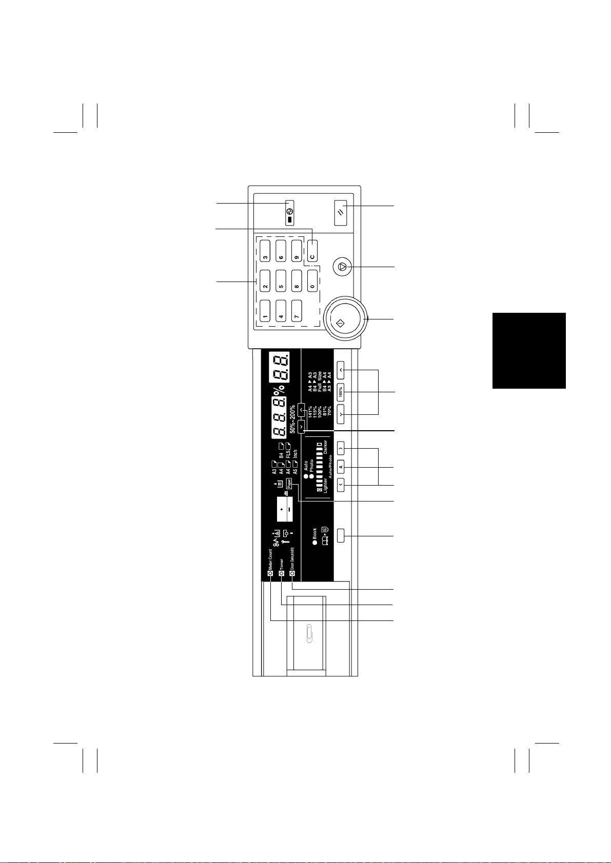
2-1.
15 cpm Copier
1. 10-Keys
Numeric keypad used for setting the num-
•
ber of copi es to be made, zoom ratio, and
Tech. Rep. mode set ti ngs.
2. Clear Key
Clear the number-of-copies setting, zoom
•
ratio, choice modes setting.
3. Energy Saver Key
Sets the copier into the Energy Saver
•
mode.
4. Panel Reset Key
Resets the copier to the initial mode.
•
5. Stop Key
Stops a multi-copy cycle or a test (F
•
operation.
6. Start Key
Starts a multi -copy cycle or a t e s t (F
•
operation.
7. Z o om R a t i o Se l e c t Key
Selects a fi xed zoom ratio.
•
8. Zoom Up/Down Keys
Changes the zoom ratio manu ally.
•
9. Auto Exposure Mod e Key
Selects either the Auto or Manual Expo-
•
sure, or Phot o mode.
10.Exposure Control Keys
Selects the exposure level .
•
11.Paper Select Key
Selects the pa per source.
•
12.Book Key
Selects the Book mode.
•
13.Drum Dehumidify Key
Runs a Drum Dehumidify cycle.
•
14.Auxiliary Toner Replenishing Key
✽
✽
Starts an auxiliary toner replenishing
•
)
sequence.
15.Meter Count Key
Gives a display of the current copy count.
•
)
NOTE
15 cpm Copier is Except for U.S.A. and Canada Areas .
S-2
Page 5
FrameMaker Ver.5.5(PC) EP1054/EP1085/EP2030 SWITCHES ON PWBs/TECH. REP. SETTINGS
98.06.09
3
2
1
4
5
6
7
8
9
10
11
S-3
12
13
14
15
1158O001DA
Page 6

FrameMaker Ver.5.5(PC) EP1054/EP1085/EP2030 SWITCHES ON PWBs/TECH. REP. SETTINGS
98.06.09
For more details, see the “Operator’s Manual” shipped with the copier.
✽
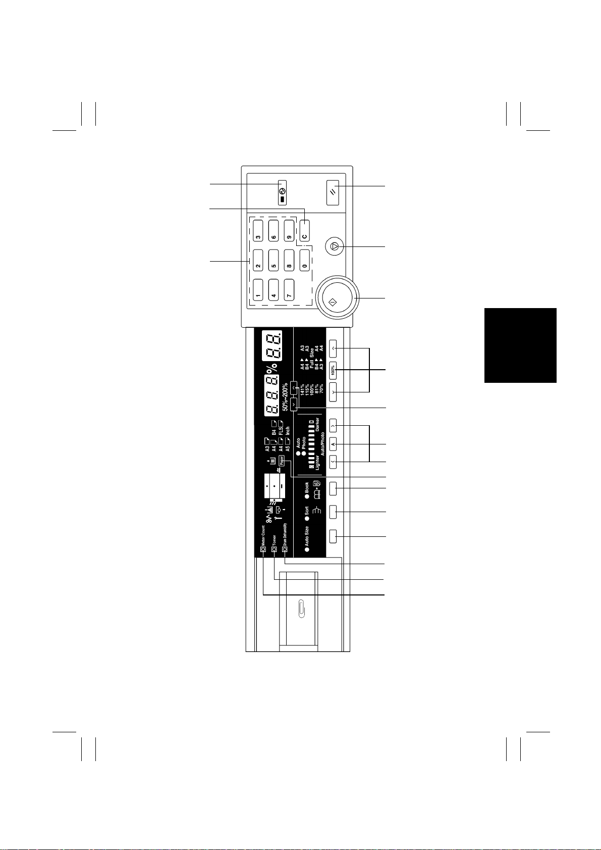
2-2. 18 cpm Copier
1. 10-Keys
Numeric keypad used for setting the num-
•
ber of copies to be made, and Tech.
Rep. mode settings.
2. Clear Key
Clear the number-of-copies setting,
•
choice modes setting.
3. Energy Saver Key
Sets the copier into the Energy Saver
•
mode.
4. Panel Reset Key
Resets the copier to the initial mode.
•
5. Stop Key
Stops a multi-copy cycle or a test (F
•
operation.
6. Start Key
Starts a multi -copy cycle or a t e s t (F
•
operation.
7. Z o om R a t i o Se l e c t Key
Selects a fi xed zoom ratio.
•
8. Zoom Up/Down Keys
Changes the zoom ratio manu ally.
•
9. Auto Exposure Mod e Key
Selects either the Auto or Manual Expo-
•
sure, or Phot o mode.
10.Exposure Control Keys
Selects the exposure level .
•
11.Paper Select Key
Selects the pa per source.
•
12.Book Key
Selects the Book mode.
•
13.Finishing Mode Select K ey
Selects the Sort mode.
•
14.Auto Size Key
✽
)
Selects the Auto Size mode.
•
15.Drum Dehumidify Key
Runs a Drum Dehumidify cycle.
•
✽
)
16.Auxiliary Toner Replenishing Key
Starts an auxiliary toner replenishing
•
sequence.
17.Meter Count Key
Gives a display of the current copy count.
•
S-4
Page 7
FrameMaker Ver.5.5(PC) EP1054/EP1085/EP2030 SWITCHES ON PWBs/TECH. REP. SETTINGS
98.06.09
3
2
1
4
5
6
7
8
9
10
11
12
S-5
13
14
15
16
17
1174S001AA
Page 8

FrameMaker Ver.5.5(PC) EP1054/EP1085/EP2030 SWITCHES ON PWBs/TECH. REP. SETTINGS
98.06.09
For more details, see the “Operator’s Manual” shipped with the copier.
✽
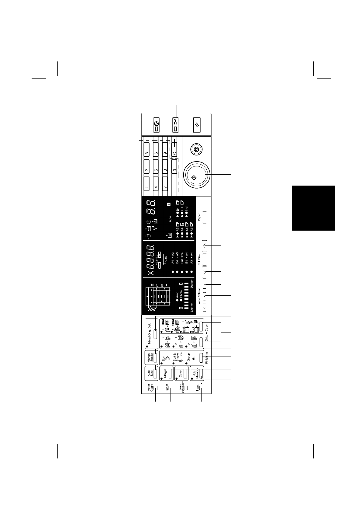
2-3. 23 cpm Copier
1. 10-Keys
Numeric keypad used for setting the num-
•
ber of copi es to be made, zoom ratio, and
Tech. Rep. mode set ti ngs.
2. Clear Key
Clear the number-of-copies setting, zoom
•
ratio, choice modes setting.
3. Energy Saver Key
Sets the copier into the Energy Saver
•
mode.
4. Interrupt Key
Sets the copier into, or lets it leave, the
•
Interrup t m ode.
5. Panel Reset Key
Resets the copier to the initial mode.
•
6. Stop Key
Stops a multi-copy cycle or a test (F
•
operation.
7. Start Key
Starts a multi -copy cycle or a t e s t (F
•
operation.
8. Paper Select Key
Selects the pap er source.
•
13.Mixed Original Detection Key
Selects the Mixed Original mode.
•
14. Orig. Copy Ke y
Selects the original-and-copy type.
•
15.Manual Staple Key
Effects manual stapling of copies.
•
16. Fi ni s h i n g Key
Selects the finishing type.
•
17.Auto Size Key
Selects the Auto Size mode.
•
18. File Margin Key
Selects the Margi n mode.
•
19. Cove r Key
Selects the Cover mode.
•
✽
20. Job Memory Select Key
)
Calls up a job program previously stored
•
in memory.
Stores a job pro gram when used in com-
•
✽
bination with the Input key.
)
21.Job Memory Input Key
Stores a j ob program in, or erases it from,
•
memory.
9. Z o om R a t i o Se l e c t Key
Selects a fi xed zoom ratio.
•
10. Zoom Up/Down Keys
Changes the zoom ratio manu ally.
•
11.Auto Exposure Mode Key
Selects either the Auto or Manual
•
Exposure, or Photo mode.
12. Exposure Control Keys
Selects the exposure level.
•
22.Drum Dehumidify Key
Runs a Drum Dehumidify cycle.
•
23.Auxiliary Toner Replenishing Key
Starts an auxiliary toner replenishing
•
sequence.
24.Meter Count Key
Gives a display of each of the current
•
counts of different electronic c ounters of
the copier.
S-6
Page 9
FrameMaker Ver.5.5(PC) EP1054/EP1085/EP2030 SWITCHES ON PWBs/TECH. REP. SETTINGS
98.06.09
45
3
2
6
1
7
8
S-7
9
10
11
12
13
14
15
16
17
18
19
20
1151O041DA
21222324
Page 10
FrameMaker Ver.5.5(PC) EP1054/EP1085/EP2030 SWITCHES ON PWBs/TECH. REP. SETTINGS
98.06.09
3
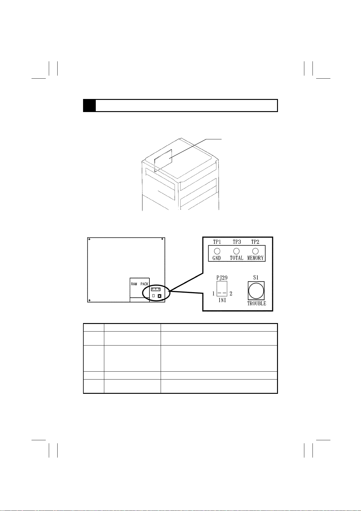
FUNCTIONS OF SWITCHES AND OTHER PARTS ON PWBs
3-1. PWB Location
PWB-A BoardTech. Rep. Setting Switches Board
1151S001AA
3-2. Tech. Rep. Setting Switches Board
Symbol Name Description
Trouble Reset Swi tc h Resets all malfu nctions including Exposure Lamp
S1
Initialize Points Forcibly resets a misfeed or malfunction that occurred
PJ2
TP1 GND Test Point Ground terminal used for memory clear.
Memory Clear Test Poi nt Initializes all data except those counted by the elec-
TP2
(C04XX) and fusin g (C 05XX) malfunctions.
due to incorrect operation, etc. when it c annot be
reset by op eni ng and closing the Front Door and turning ON S1.
tronic counters.
S-8
1151S002AA
Page 11
FrameMaker Ver.5.5(PC) EP1054/EP1085/EP2030 SWITCHES ON PWBs/TECH. REP. SETTINGS
98.06.09
<Clearing Procedures>
Initialize P oin ts PJ2
•
1. Turn OFF the Power Switch.
2. With PJ2 closed, t urn ON the Power Switch .
3. In approx. 5 sec ., open PJ2.
Memory Clear Test Point TP2
•
1. Turn OFF the Power Switch.
2. With the circuit acros s TP1 and 2 closed, t urn ON t he Power Switch.
3. In approx. 5 sec ., open the circu i t across TP1 and 2.
NOTE
If an erratic operation or display occurs, perform the clearing procedures in the order of
•
PJ2 and TP2.
When memory clear has been performed, make the necessary settings again.
•
<List of Data Cleared by Switches and Points>
Clearing Means
Data Cleared
Misfeed display
Malfunction display
(excluding Exposure
Lamp and fusing
malfunctions)
Malfunction display
(including Exposure
Lamp and fusing
malfunctions)
Erratic operation/display
User mode
Serv ice mode
F3/5/8 adjustment values
Adjust mode
: Cleared− : Not cleared
❍
Front Door
Open/Clos e
❍❍❍❍
❍❍❍❍
− ❍❍❍
−−❍❍
−−−❍
−−−❍
−−−❍
−−−❍
Trouble Reset
Switch
(S1)
Initialize
Points
(PJ2)
Memory Clear
Test Point
(TP2)
S-9
Page 12

FrameMaker Ver.5.5(PC) EP1054/EP1085/EP2030 SWITCHES ON PWBs/TECH. REP. SETTINGS
98.06.09
4 USER MODE
This mode is used to make various settings according to the user’s needs.
•
4-1. Functions A vailable from the User Mode
No. Function No. Function
✽
Mixed Original Detection
0
✽✽
Lightweight Original 20 Auto clear ON/OFF
4
✽
Smaller Originals 21 Energ y Saver ON Timing
6
7 Auto Power OFF Disabling
✽
File Margin
9
✽
Priority Paper Size/Source 28 Auto Power OFF Timing
10
✽✽
APS/AMS/Manual Priority
12
13 Optimum Ex posure Level
Priority Manual Ex posure
14
Level
✽✽
Finishing Mod e Priority
15
✽
Priority Orig. Copy type
18
✽✽
✽✽
✽
For 23 cpm Copier only
✽✽
For 18/23 cpm Copier only
Auto Clear for Plug-In
23
Counter
Sort/Non-Sort Switching
24
ON/OFF
Special Paper Setting
✽
51
(1st Drawer)
Special Paper Setting
✽
52
(2nd Drawer)
Special Paper Setting
✽
53
(3rd Drawer)
Special Paper Setting
✽
54
(4th Drawer)
4-2. User Mode Setting Procedure
<Setting Pro cedure>
1. Hold down the Panel Reset key for about 3 sec onds to set the copi er into the User
mode. (“U” appears on the Zoom Ratio Indicator.)
2. From the 10-Keys, enter the number assigned to the desired function. (The number
entered appears following the letter “U” on the Zoom Ratio Indicator.)
3. Press the Start ke y. (Then, the curr ent set tin g f or tha t particul ar functi on app ears on th e
Multi-Copy Display.)
4. Press the Clear key.
5. M ak e a new setting.
6. Press the Start key to vali date the entry of the ne w setting.
Note
If the sett in g dat a ente red i s ou tsi d e the s peci fi cat ions , it is not validated and is shown b l i nking.
<Resetting Procedure>
Press the Panel Reset key to return to the Basic screen.
•
S-10
Page 13

FrameMaker Ver.5.5(PC) EP1054/EP1085/EP2030 SWITCHES ON PWBs/TECH. REP. SETTINGS
98.06.09
[User Mode]
4-3. User Mode Setting Details
Function N o.
U-0
✽
For 23 cpm
Copier only
U-4
✽✽
For 18/23 cpm
Copier only
U-6
✽
For 23 cpm
Copier only
Setting (The default is .)
<Mixed Original Detection>
Select whethe r to turn ON the Mix e d Original D etectio n func tion or no t
(high-speed proce ssing).
ON: The copier enables its A uto Paper Selection (APS) or Auto Size
Selection (AMS) function for a ll originals loaded in the ADF (i.e.,
it can make copies from original s of assorted sizes loaded in a
set).
OFF:The copier enables its APS/AMS function only for the first
original loaded in the ADF.
Data 0
Mixed Original Detection
Description
Select whether to turn ON the Lightw eight Original function or not
when the ADF is used.
Data 1
Description
Select whether to enable (“ON”) a copy cycle or not (“OFF”) when it is
initiated by pressing the Start key with an original of the smallest
detectable size (metric areas: A5 or smaller; inch areas: Letter or
smaller) placed on the Original Glas s.
The copy cycle is run using the
paper loaded in th e def aul t pap er
source.
function ON
<Lightweight Original>
0
Normal
The original is pres sed
against th e Original Width
Scale when stopped.
<Smaller Originals>
ON OFF
Highlighted
1
Mixed Original Detection
function OFF (high-speed
processing )
Lightweight Original
The original is not
pressed against the Origi-
nal Width Scale when
stopped.
A warning message is given and
the copier i nhibits the start of t his
copy cycle.
NOTE
The default setting is OFF for the metric areas and ON for the inch
areas.
S-11
Page 14

FrameMaker Ver.5.5(PC) EP1054/EP1085/EP2030 SWITCHES ON PWBs/TECH. REP. SETTINGS
98.06.09
[User Mode]
Function N o.
U-7 <Auto Power OFF Disabling>
Select whether to enable or disable the setting of “0: Disabled” for
“Auto Power OFF Timing” available from the User mode.
Data 1
Description Disabled Enabled
U-9
✽
For 23 cpm
Copier only
U-10
✽
For 23 cpm
Copier only
Select the margin making method in the File Margin mode.
Data 1
Description
Select the priority paper size or paper source selected when the
copier is set into the AMS or Manual mode.
Data Description Data Description
0
1
2
3
4
5
6
7
Default: 15 (i nch areas) / 6 (met ric areas)
L: lengthwise; C : c r osswise
Setting (The default is .)
0
<File Margin>
0
File Margin mode when
the original has a file mar-
gin.
<Priority Paper Size/Source>
A3 (L)
B4 (L)
A4 (L)
B5 (L)
A5 (L)
FLS (L)
A4 (C)
B5 (C)
10
11
12
13
14
15
20
21
22
23
Highlighted
File Margin mode when
the original does not hav e
a file margin.
11” × 17” (L)
11” × 14” (L)
Legal (L)
Letter (L)
5-1/2” × 8-1/2” (L)
Letter (C)
1st Drawer
2nd Drawer
3rd Drawer
4th Drawer
U-12
✽✽
For 18/23 cpm
Copier only
NOTE
If a paper size or s ource tha t does not e xis t is selec ted, the 1st Draw er
(20) is automatically selected.
<APS/AMS/M anual Priority>
Select the priority copying mode that is automatically selected when
the Power Switch is turned ON or Panel Reset key is pressed.
[23 cpm Copier]
Data 1 2
Description APS AMS Manual
[18 cpm Copier]
Data 1
Description AMS Manual
0
2
S-12
Page 15

FrameMaker Ver.5.5(PC) EP1054/EP1085/EP2030 SWITCHES ON PWBs/TECH. REP. SETTINGS
98.06.09
[User Mode]
Function N o.
U-13 <Optimum Exposure Level>
Determine the optim um e xp osure level in the Auto as w ell as the Manual Exposure mode.
Data Description Data Description
46
47
48
49
U-14 <Priority Manual Expos ure Level>
Determine the priority exposure level for the Manual Exposure mode.
The level determines the priority exposure level selected when the
exposure mode is switched from the initial Auto to Manual, and when
Manual Exposure is initially selected when power is turned ON.
Data Description Data Description
0
1
2
3
4
5
6
7
8
Setting (The default is .)
Low level 4: – 2.0 steps
Low level 3: – 1.5 steps
Low level 2: – 1.0 steps
Low level 1: – 0.5 steps
[Auto Manual]
EXP.1
Auto
Auto EXP.2
Auto
EXP.3
Auto
EXP.4
Auto EXP.5
Auto
EXP.6
Auto
EXP.7
Auto EXP.8
Auto
EXP.9
50
51
52
Highlighted
10 Manual EXP.1
11 Manual EXP.2
12 Manual EXP.3
13 Manual EXP.4
14 Manual EXP.5
15 Manual EXP.6
16 Manual EXP.7
17 Manual EXP.8
18 Manual EXP.9
Standard ±0 steps
High level 1: +0.5 steps
High level 2: +1.0 steps
[Manual]
U-15
✽✽
For 18/23 cpm
Copier only
Determine the priority fi nishing mode sele ct ed when the copier is
equipped with a finishing opti on.
[23 cpm Copier]
Data 1 2 3
Description Non-Sort Sort Group
[18 cpm Copier]
Data 1
Description Non-Sort Sort
<Finishing Mode Priority>
0
Sort-and-
Staple
0
S-13
Page 16

FrameMaker Ver.5.5(PC) EP1054/EP1085/EP2030 SWITCHES ON PWBs/TECH. REP. SETTINGS
98.06.09
[User Mode]
Function N o.
U-18
✽
For 23 cpm
Copier only
Determine the orig. copy type automatically selected when t he
Power Switch is turned ON or Panel Reset k ey is p ressed. The setting
made in “C-40 (Orig. Copy Type)” available as one of the Tech.
Rep. Choice functio ns determines the details of orig. copy type
selected by the setting of this function.
[When “0” is set for C-40] [When “1” is set for C-40]
Data Description Data Description
0 0
1
2
3
4
Setting (The default is .)
<Priority Orig. Copy Ty pe >
1 ➡ 1
1 ➡ 2
2 ➡ 2
1 ➡ 1 2in1
1 ➡ 2 2in1
NOTE
2in1 = Enabled when an ADF is mounted.
2 = Enabled when a Duplex Unit is mounted.
U-20 <Auto Clear ON/OFF>
Select whether o r not to activate the auto clea r ( panel reset) function
after the lapse of a given perio d of time after a copy cycle has been
completed or a key on the control panel has been operated.
Data 0 1
Description Disabled Enabled: 30 sec. Enabled: 1 min.
Highlighted
1
2
3
4
1 ➡ 2
1 ➡ 2
2 ➡ 2
1 ➡ 2 2in1
1 ➡ 2 2in1
2
U-21 <Energy Saver ON Timing>
Select whether o r not to set the copi er i nto the Energy Saver mode
after the lapse of a given perio d of time after a copy cycle has been
completed or a key on the control panel has been operated.
Data Description Data Description
15
1
2
.
.
.
Enabled: 1 min.
Enabled: 2 min.
.
.
.
Enabled: 15 min.
.
.
.
97
98
99
NOTE
Except for 99, the setting data equals the ti me i n minutes.
S-14
.
.
.
Enabled: 97 min.
Enabled: 98 min.
Enabled: 240 min.
Page 17

FrameMaker Ver.5.5(PC) EP1054/EP1085/EP2030 SWITCHES ON PWBs/TECH. REP. SETTINGS
98.06.09
[User Mode]
Function N o.
U-23
✽✽
For 18/23 cpm
Copier only
Select w hether to ac t i vat e the auto clear (panel reset) func ti o n w hen
the Plug-In Counter is pulled out.
Setting (The default is .)
<Auto Clear for Plug-In Counter>
Data 0
Description Auto clear is not activated. Auto clear is activated.
U-24
✽✽
For 18/23 cpm
Copier only
Select wheth er to enable or disable the function that automatically
switches between the Sort and Non-Sort mode depending on the
number of origi nal s loaded in the ADF when the copier is equipped
<Sort/Non-Sort Switching ON/OFF>
with an ADF and finishing opti on.
Data 0
Description OFF (disabl ed) O N ( enabled)
U-28 <Auto Power OFF Timing>
Select whether or not to enable the auto power OFF function that
turns power o ff automatica l ly after the lapse of a given period of time
after a copy cycle has been completed or a key on the control panel
has been oper ated.
Data Description Data Description
0
1
2
.
.
✽
30
✽
30: 15/18 cpm Copier 60: 23 cpm Copier
Disabled
Enabled: 1 min.
Enabled: 2 min.
.
.
Enabled: 30 min.
Highlighted
✽
60
.
.
97
98
99
1
1
Enabled: 60 min.
.
.
Enabled: 97 min.
Enabled: 98 min.
Enabled: 240 min.
U-51 to 54
✽
For 23 cpm
Copier only
NOTES
1. Except for 0 and 99, the setting data equals the time in minutes.
2. “0” cannot be selected for this function if U-7 (Auto Power OFF
Disabling) ava ilable as one of the User Mode functions is set to
“0.”
<Special Paper Setting>
Designates each drawer of the copier f or special pap er.
U-51: 1st Drawer
U-52: 2nd Draw er
U-53: 3rd Drawer
Data 1
Description Plain paper Special paper
0
U-54: 4th Drawer
NOTE
The APS mode is disabled if “1” is set.
S-15
Page 18

FrameMaker Ver.5.5(PC) EP1054/EP1085/EP2030 SWITCHES ON PWBs/TECH. REP. SETTINGS
98.06.09
5 SERVICE MODE
This mode is used by the Tech. Rep. to set, check, adjust, and/or program various ser-
•
vice functions.
5-1. Service Mode Function Tree
F1 : Paper passage test
F2 : PC Drum Charge/Image Transfer Coronas output
F3 : Exposure Lamp voltage adjustment
F4 : Paper Separator Corona output
F5 : AE Sensor automatic adjustment
F6 : Edge Er ase Lamp check
✽
F7 : Original Size Detecting Unit adjustment
F8 : ATDC Sensor automatic adjustment
F9 : IU check, optimum exposure adjustment
FA : Scanner/Image Erase Lamp operation check
✽
C-0 : Plug-In Counter counting
C-1 : Size Counter counting
C-2 : Total Counter counting
C-4 : Maintenance Call Reminder ON/OFF
C-5 : PM Counter
✽✽
C-6 : Plug-I n Counter c opyi ng enable/dis abl e
C-7 : IU 60K stop
C-15 : Toner empty stop
C-20 : Leading edge er ase
C-21 : Trailing edge erase
C-23 : Loop length adjustment
✽✽
C-31 : 1-sided original stop position adjustment
✽
C-32 : 2-sided original stop position adjustment
✽
C-33 : 2-in-1 original stop position adjustment
✽
C-34 : 2-in- 1 original d istance adjust ment
✽✽
C-37 : S-AD F mode ori ginal stop position adjustm ent
✽✽
C-38 : AD F Registration Loop adjust ment
✽
C-40 : Orig. copy type
C-90 : ATDC detection level
✽
For 23 cpm Copier only
✽✽
For 18/23 cpm Copier only
Service
Mode
Test
Service Mode No. 1
Te ch. Rep.
Choice
Service Mode No. 2
Altering Fixed Zoom Ratios
✽
For 23 cpm Copier only
Service Mode No. 3
~
S-16
Page 19

FrameMaker Ver.5.5(PC) EP1054/EP1085/EP2030 SWITCHES ON PWBs/TECH. REP. SETTINGS
98.06.09
~
PM Counter and Ports/Options Counter
Paper Size Counter
Service
Mode
Misfe ed C ounter
Malfunction Counter
Parts/Supplies Life Counter
Paper Size Input
✽
For 23 cpm Copier only
Display
5-2. Entering the Service Mode
Service Mode No. 4
Service Mode No. 5
Service Mode No. 6
Service Mode No. 7
Service Mode No. 8
Service Mode No. 9
Service Mode No. 0
<Procedure>
1. Press the Meter Count key. Then, press the followi ng keys in this order.
Press the
Stop key.
Press “0.”➡Press “0.”
➡
➡
Press the
Stop key.
Press “0.”➡Press “1.”
➡
2. From the 10-Keys, press the nu mber corresponding to the service mode no. assigned.
3. Perform the necessary steps for the function selected.
<Leavin g the Service Mode>
Press the Panel Reset key twice to go back to the Basic screen.
•
S-17
Page 20

FrameMaker Ver.5.5(PC) EP1054/EP1085/EP2030 SWITCHES ON PWBs/TECH. REP. SETTINGS
98.06.09
5-3. Settings in the Service Mode
(1) Test
This function allows the Tech. Rep. to perform various functional tests and adjustments.
•
<Setting Pro cedure>
1. Enter the number assigned to the desired test from the 10-Keys. (The number appears
on the Multi-Copy Display.)
2. Press the Start key to start the test.
3. Press the Stop key to stop the test.
<Test Copy>
A test copy can be made by entering “F3, F5” of the Test No., holdin g down the Stop key
•
and pressing the Start key.
<Leaving the Functi on>
Press the Panel Reset key twice to go back to the Basic screen.
•
[Service Mode Test]
Test No. Description
F1 <Paper Passage Test>
F2 <PC Drum Charge/Image Transfer Coronas Output>
F3 <Exposure Lamp Voltage Adjustment>
A paper passage test is carried out to check for correct sensor operation without having to wait for th e copier to compl ete warming up. It
provides the following two modes:
1. Normal mode (The Zoom Ratio Indicator shows “On.”)
2. Load OFF mode, in which some parts are put in an inactive state
(The Zoom Ratio Indicator shows “Off.”)
<Procedure>
1. Using the Zoom Up /Down key, select either one of the two modes.
2. Pr e ss th e St art key.
<To quit>
Press the Stop key, or the test stops when paper runs out.
•
Do not use this test as it is only for factory adjustment.
This test allows the Tech. Rep. to adjust the maximum Exposure
Lamp voltage and the optimum exposure setting in the Manual Exposure mode. (It runs for 30 sec.)
NOTE
For details, see DIS/REASSEMBLY, ADJUSTMENT.
F4 <Paper Separator Corona Output >
Do not use this test as it is only for factory adjustment.
F5 <AE Sensor Automatic Adjustment>
This test automatically adjusts the AE Sensor. (It runs for 5 sec .)
NOTE
For details, see DIS/REASSEMBLY, ADJUSTMENT.
S-18
Page 21

FrameMaker Ver.5.5(PC) EP1054/EP1085/EP2030 SWITCHES ON PWBs/TECH. REP. SETTINGS
98.06.09
[Service Mode Test]
Test No. Description
F6 <Image Erase Lamp Check>
This test checks whether the Image Erase Lamp turns ON and OFF
properly.
(It runs for one complete copy cycle.)
<Procedure>
Press the Start key after the copier has compl eted warming up.
•
This causes th e l amp to make a checkered pattern.
F7
✽
For 23 cpm
Copier only
This test automatically adjusts the Original Size Detecting Sensors,
starting when the Start key is pressed. (It runs for 5 sec.)
<Original Size Detecting Unit Adjustment>
F8 <ATDC Sensor Automatic Adjustment>
This test automatically adjusts the ATDC Sensor. (It runs for about 5
min.)
NOTE
For details, see DIS/REASSEMBLY, ADJUSTMENT.
F9 <IU Check, Optimum Exposure Adjustment >
Do not use this test as it is only for factory adjustment.
FA <Scanner/Image Erase Lamp Operation Check>
Do not use this test as it is only for factory adjustment.
– Components Energized in the Tests –
Component
Test Operation
Main Drive Motor
PC Drum Drive Motor
Fan Motors
Toner Replenishing Motor
HV (PC Drum Charge, Image
Transfer, grid)
Bias (Developing, Separator, seal)
Scanner
Paper Take-Up Roll
Paper Transport Rollers
Synchronizi ng R ol lers
Exposu r e La m p
Main Erase Lamp
Image Erase Lamp
PC Drum Paper Separator Fingers
Misfeed detection
Malfunction detection
: Energized − : Remain deenergized
❍
✽
F1 : Deenergized in the load OFF mode.
✽
F3/5 : The Scanne r st ops at the TRO N position.
✽
F6 : Turned ON and OFF alternately to make a checkered pattern.
F1 F2 F3 F4 F5 F6 F7 F8 F9 FA
❍❍❍❍❍❍−❍❍
❍❍❍❍❍❍−❍❍
❍❍❍❍❍❍−❍❍
−−−−−−−❍−−
✽
✽
❍
❍
❍
❍
✽
❍❍❍❍❍❍−❍❍
✽
❍
❍
❍❍❍❍❍❍❍❍❍❍
−−−❍−
❍
−
❍❍❍❍−❍❍
✽
−
−−−−❍−−−−
−−−−❍−−−−
−−−−❍−−−−
−
❍
−
❍❍❍
−−−−❍−−−−
−−−−❍−−−−
−
−
✽
❍❍
−−
❍
−−❍−
✽
−
❍❍
❍❍
−
❍
−
−
−
−
−
−
❍
S-19
Page 22

FrameMaker Ver.5.5(PC) EP1054/EP1085/EP2030 SWITCHES ON PWBs/TECH. REP. SETTINGS
98.06.09
(2) Tech. Rep. Choice
This function allows the Tech. Rep. to make various settings and ad jus tm e nts.
•
<Setting Pro cedure>
1. Press “2” from the 10-Keys. (The Zoom Ratio Indicator shows “C.”)
2. Press the number assigned to the desired Tech. Rep. Choice. (The Zoom Ratio Indicator shows “C” pl us the number of the chosen functi on.)
3. Press the Start key. (The Multi-Copy Display shows the current setting for the chosen
function.)
4. Clear the current setting using the Clear key and enter the new setting from the 10-Key
Pad.
5. Press the Start key to vali date the new setting.
NOTE
If the setting is illegal, it is not validated and is show n blinking.
<Test Copy>
A test copy can be made by entering “C” of the Tech. Rep. Choice No., holding down the
•
Stop key and pressing the Start key.
<Leaving the Functi on>
Press the Panel Reset key twice to go back to the Basic screen.
•
[Service Mode Tech. Rep. Choice]
Choice No.
C-0
✽
For 23 cpm
Copier only
Select the condition by which the Plug-In Counter coun t is increased.
Data 1
Description
Setting (The default is .)
<Plug-In Counter Counting>
0
Counts the number of
sheets of paper fed out.
NOTE
See the Count-up Table for d etails.
C-1 <Size Counter Counting>
Select the size of the paper to be counted by the Siz e Counter.
Data 0 2 3
Description
(Metric
areas)
Description
(Inch areas)
No count A3 A3/B4 A3/B4/FLS
No count 11” × 17”
1
NOTE
See the Count-up Table for d etails.
Highlighted
Counts the number of
copy proc esses carried
11” × 17”,
8-1/2” × 14”
out.
8-1/2” × 14”,
11” × 17”,
11” × 14”
S-20
Page 23

FrameMaker Ver.5.5(PC) EP1054/EP1085/EP2030 SWITCHES ON PWBs/TECH. REP. SETTINGS
98.06.09
[Service Mode Tech. Rep. Choice]
Choice No.
C-2 <Total Counter Counting>
Select the conditions (paper size and 2-sided copying) by which the
Total Counter count is increased.
Data 1 2
Description
Setting (The default is .)
0
1 count per 1
copy cycle
Highlighted
Multiple count-up Mu ltiple count-up
NOTE
See the Count-up Table for d etails.
<Count-up Table>
Copying 1-Sided 2-Sided
Sizes
Size
Total
Total (mechani-
cal, electronic)
Size
(electronic)
2-Sided Total
(electronic)
2-Sided Size
(electronic)
Plug-In
(mech
anical)
0: No count 1: 1 coun t 2: 2 counts 4: 4 counts
C-4 <Maintenance Call Reminder ON/OFF>
Select whether to enable or disable the maintenance call reminder.
Data 1
Description
other than
those set
Mode Mode Mode Mode
012012012012
Count-
ing
copies
Count-
ing
copy
cycles
The maintenance call
reminder is not given.
Set sizes
112222441
011202200
0 0 112114 0
0 0 0 114 0
1 122122144 1
112222441
0
Sizes
other than
those set
Set sizes
The maintenance call
reminder is given.
Manual
Bypass
S-21
Page 24

FrameMaker Ver.5.5(PC) EP1054/EP1085/EP2030 SWITCHES ON PWBs/TECH. REP. SETTINGS
98.06.09
[Service Mode Tech. Rep. Choice]
Choice No.
C-5 <PM Counter>
Select either PM Counter or Copy Kit Counter.
Data Description
0
1
2
Setting (The default is .)
Copy Kit Counter: Copying not inhibited after the
Copy Kit Counter: Copying inhibited after the counter
Highlighted
PM Counter
counter has counted down to zero.
has counted do wn to zero.
NOTE
If this function is set to “2,” the copier gives an i n dication to replace
the IU and inhibits the initiation of a new copy cycle even if C-4 is set
to “0.”
C-6
✽✽
For 18/23 cpm
Copier only
Select wheth er to enable or di sable copying according to whethe r the
Plug-In Counter is plugged in or not.
Description
<Plug-In Counter Copying Enable/Disable>
Data 1
Permits copying even
when the Plug-In Counter
0
is not plugged in.
NOTE
Be sure to set this function to “1” when the Plug-In Counter is
installed.
C-7 <IU 60K Stop>
C-15 <Toner Empty Stop>
Select whether or not to inhibit copying when IU Counter has counted
60K.
Data 0 1
Description Permits copying. Inhibits copying.
Default: 0 (inch areas) / 1 (metric areas)
Select whether or not to inhibit copying when a toner-empty condition
is detected.
Data 1
Description Permits copying. Inhibits copying.
0
NOTE
If “1” is set, the copier inhibit s copying w hen it detects a T/C of 3.5%
or lower .
Inhibits copying when the
Plug-In Counter is not
plugged in.
S-22
Page 25

FrameMaker Ver.5.5(PC) EP1054/EP1085/EP2030 SWITCHES ON PWBs/TECH. REP. SETTINGS
98.06.09
[Service Mode Tech. Rep. Choice]
Choice No.
Setting (The default is .)
Highlighted
C-20 <Leading Edge Erase>
V aries the width of er ase on the leading e dge.
Data 0
1
Description Smaller width Greater width
NOTE
When the setting is changed, it results in the erase width being
changed by about 3 mm.
C-21 <Trailing Edge Erase>
Varies the width of erase on the trailing edge.
Data 0
Description Smaller width Greater width
NOTE
When the setting is changed, it results in the erase width being
changed by about 3 mm.
C-23 <Loop Length Adjustment>
Adjust the length of the loop to be formed in paper before the Synchronizing Rollers.
Data Description Data Description
Loop length about 4.9 mm
47
Loop length about 5.6 mm
48
Loop length about 6.3 mm
49
Loop length about 7.0 mm
50
C-31 to 34
✽
For 23 cpm
Copier only
✽✽
For 18/23 cpm
Copier only
Adjust th e po siti on at whic h to s top th e o rig inal in each of t he f o llo w ing
ADF modes.
✽✽
C-31: 1-sided original stop position adjustment
✽
C-32: 2-sided original stop position adjustment
✽
C-33: 2-in-1 original stop position adju stment
✽
C-34: 2-in-1 original distance adjustment
✽✽
C-37: S-ADF mode original stop position adjustment
✽✽
C-38: ADF Registration Loop adjustment
Data
Adjustment
Value
<Original Stop Position Adjustment>
43.................................... .................................58
7 mm
−
.............................±
1
Loop length about 7.7 mm
51
Loop length about 8.4 mm
52
Loop length about 9.1 mm
53
50
0 mm........................+8 mm
NOTE
The stop posit ion is farther away from the Original Width Scale (or a
greater distance betwee n 2-i n-1 originals ) i n the + direction.
S-23
Page 26

FrameMaker Ver.5.5(PC) EP1054/EP1085/EP2030 SWITCHES ON PWBs/TECH. REP. SETTINGS
98.06.09
[Service Mode Tech. Rep. Choice]
Choice No.
C-40
✽
For 23 cpm
Copier only
Determine the orig. copy types that can be selecte d i n the “Priority
Orig. Copy Type” available from the User mode .
Data 0
Description
Setting (The default is .)
<Orig. Copy Type>
All orig. copy types can
be selected.
Highlighted
Only the types involving
2-sided copy can be
selected.
1
C-90 <ATDC Detection Level>
Select the ATDC control level (T/C ratio).
Data Description Data Description
48
49
50
T/C ratio 5.0 %
T/C ratio 5.5 %
T/C ratio 6.0 %
51
52
53
T/C ratio 6.5 %
T/C ratio 7.0 %
T/C ratio 7.5 %
S-24
Page 27

FrameMaker Ver.5.5(PC) EP1054/EP1085/EP2030 SWITCHES ON PWBs/TECH. REP. SETTINGS
98.06.09
(3) Altering Fixed Zoom Ratios (For 23 cpm Copier Only)
This function allows the Tech. Rep. to ch ange the fixed zoom ratios ove r the range
•
between ×0.500 and ×2.000 according to the needs of the user.
<Setting Pro cedure>
1. Se l ect the Altering Fixed Zo om R atios func ti o n.
2. Select the particular fixed zoom ratio to be changed and press the Clear key to clear it.
NOTE
If the zoom ratio is cleared mistakenly, press the Panel Reset k ey to undo the clearing operation.
3. Enter the desired z oom ratio from the 10-Keys.
4. Press the Start key to vali date the new zoom ratio.
(4) PM Counter and Ports/Options Counter
This function shows the counts of the PM Counter (IU) and Ports/Options Counter. The
•
particular port or option is i ndi cated by the c orresponding LED of the Misfeed Monitor.
The count is shown across the “Zoom Ratio Indicator” and “Multi-Copy Display.”
NOTE
The PM Counter is indicated by the IU Service Life Indicator LED.
Example) Count: 12345
Multi-Copy Display
123
Zoom Rat i o I n di cator
45
Counting System
PM Counter: Count- do wn t ype (Whe n th e count er has count ed dow n to zero, a − (minus)
•
sign appears in the Zoom Ratio Indicator and the count is thereafter incremented.
Ports/Options Counter: Count-up type
•
<Setting Pro cedure>
1. Select the PM Counter and Ports/Options Counter func tion.
2. Each press of the Paper Select key lights up a new LED representing the ne w counter
in the following order.
[23 cpm Copier]
Order Description Order Description
Manual bypass
PM Counte r
1
1st Drawer
2
2nd Draw er
3
3rd Drawer (Paper Feed Cabinet)
4
4th Drawer (Paper Feed Cabinet)
5
6
7
8
9
10
Duplex take-up
Sorter
Stapling
ADF
NOTE
PF-112, if the copier is so equipped, is indicated by the 3rd Drawer LED only.
[18 cpm Copier] [15 cpm Copier]
Order Description Order Description
1
PM Counter
1
Copier paper source
2
Manual by pa s s
3
Sorter
4
ADF
5
PM Counter
2
Copier paper source
3
Manual bypass
S-25
Page 28

FrameMaker Ver.5.5(PC) EP1054/EP1085/EP2030 SWITCHES ON PWBs/TECH. REP. SETTINGS
98.06.09
<Setting a PM Counter Count>
1. Show the count of t he PM C ounter (IU Service Life Indicator) and clear it.
2. Enter the desired count from the 10-Keys.
NOTE
Press the Sto p key to undo the clearing command.
3. Press the Start key to vali date the new count setting.
<Clearing a Count>
Show the count of the counter to be cleared and press the Clear key. If a count is mistak-
•
enly cleared , press the Stop key to undo the clearing command.
(5) Paper Size Counter
This function shows the counts of different sizes of paper.
•
The paper size is indicated by the Paper Select LE D. The count is shown across the
“Zoom Ratio Indicator” and “Multi-Copy Display.”
Example
Count: 12345
<Setting Pro cedure>
1. Select the P aper Size Count er function.
2. Each press of the Paper Select key lights up a new LED representing the ne w counter
in the following order.
[23 cpm Copier: Metric are as] [23 cpm Copier: Inch areas]
Order Description Order Description
1
2
3
4
5
6
[15/18 cpm Copi er: Metric areas] [15/18 cpm Copier: Inch areas]
Order Description Order Description
1
2
3
4
5
6
<Clearing a Count>
Show the count of the counter to be cleared and press the Clear key. If a count is mistak-
•
enly cleared , press the Stop key to undo the clearing command.
Multi-Copy Display
123
A3
A4
A5
B4
FLS
Inch
A3
A4
A5
B4
FLS
Inch
Zoom Ratio Indicator
45
1
2
3
4
5
6
1
2
3
4
5
6
Legal
Letter
11” × 17”
11” × 14”
Invoice
Metric
Legal
Letter
11” × 17”
11” × 14”
Invoice
Metric
S-26
Page 29

FrameMaker Ver.5.5(PC) EP1054/EP1085/EP2030 SWITCHES ON PWBs/TECH. REP. SETTINGS
98.06.09
(6) Misfeed Counter
This function shows the number of misf eeds that have occurred at different locations in
•
the copier (count-up type counter). The Monitor Dis play tells the location of the misfeed
by a lit LED. The count is sho w n o n the Zoom Ratio Indicator and the mi sfeed code is
given on the Mul ti-Copy Display.
Example
Misfeed location: Manual bypass
Count: 123
<Setting Pro cedure>
1. Se l ect the Misfeed Counter f un ction.
2. Each press of the Paper Select key lights up a new LED representing the ne w counter
in the following order.
[23 cpm Copier]
Order Description Order Description
Manual bypass
1
1st Drawer
2
2nd Draw er
3
3rd Drawer (Paper Feed Cabinet)
4
4th Drawer (Paper Feed Cabinet)
5
Duplex take-up/tr ansport
6
Paper ta ke-up/transport
7
Separator
8
Exit
9
Zoom Ratio Indicator
123
Storage/transport
10
J
Storage
11
J
J
J
J
J
J
J
J
Sorter
12
ADF (take-up)
13
ADF (transport)
14
ADF (exit)
15
ADF (turnover)
16
ADF (single feed)
17
Multi-Copy Display
J
JA
Jb
Jc
Jd
JE
NOTE
PF-112, if the copier is so equipped, is indicated by the 3rd Drawer LED.
[15 cpm Copier] [18 cpm Copier]
Order Description Order Description
Manual bypass
1
Copier paper take-up/
2
transport
Take-up/transport
3
Separator
4
Exit
5
Sorter
6
ADF
7
J0
J0
J1
J2
J3
JA~JE
Manual bypass
1
Copier paper take-up/
2
transport
Take-up/transport
3
Separator
4
Exit
5
J
J0
J0
J1
J2
J3
J
J
J
<Clearing a Count>
Show the count of the counter to be cleared and press the Clear key. If a count is mistak-
•
enly cleared , press the Stop key to undo the clearing command.
S-27
Page 30

FrameMaker Ver.5.5(PC) EP1054/EP1085/EP2030 SWITCHES ON PWBs/TECH. REP. SETTINGS
98.06.09
(7) Malfunction Counter
This function shows the number of malfuncti ons that have occurred at di fferent locations
•
in the copier (count-up type counter). The Zoom Ratio Indicator shows the malfunction
code, while the Multi-Copy Display shows the count.
Example
ATDC Sensor malfunction (F30)
Count: 12
Zoom Ratio Indicator
F30
Multi-Copy Display
12
<Setting Pro cedure>
1. Se l ect the Malfunction Counter f u nc t i on.
2. Each press of the Paper Select key shows the count of a ne w counter in the following
order.
NOTE
The count is gi ven only if it is not “0.” If all counts are “0,” the message “All 0” is shown.
Order Malfunction Co de Descrip ti on
1
2
3
4
5
6
7
8
9
10
11
12
13
14
15
16
17
18
19
20
21
22
23
24
25
26
27
28
29
30
31
32
33
For 18 cpm Copi er, the counter counts are shown in the order of 1 to 11, 18, 19, 25 and
✽
000
010
04C
070
400
500
510
520
600
610
620
900
950
990
998
99E
F02
F10
F30
F79
FE1
b10
b30
b50
b60
d00
d20
d50
E1
E2
Ar1
Ar2
Ar3
A Main Drive Motor malfunction
A PC Drive Moter malfunction
A Cooling Fan Motor malfunction
A Toner Replenishing Motor malfunction
An Exposure Lamp malfunction
An abnormally low fusing temperature during warm-up
An abnormally low fusing temperature after completion of warm-up
An abnormally high fusing temperature
A Scanner drive system malfunction
A Lens drive system malfunction
A Mirror drive system malfunction
A 1st Drawer malfunction
A 2nd Drawer malfunction
A Paper Feed Cabinet Main Tray malfunction
A Paper Feed Cabinet Shift Tray malfunction
A Paper Feed Cabinet
An Original Size Detecting Unit malfunction
An AE Sensor malfunction
An ATDC Sensor malfunction
A Paper Empty Sensor malfunction
An Original Size Detecting Sensor malfunction
A Sorter Paper Clamp Unit moving malfunction
A Sorter Paper Aligning Motor malfunction
A Sorter Staple Unit malfunction
A Sorter Bin moving mechanism malfunction
A Duplex Unit Guide Plates malfunction
A Duple x Uni t entrance port switching failure
A Duplex Drive Motor malfunction
A star t er charging failure
An ATDC automatic adjustment/IU fuse blowing failure
Copier watchdog
ADF watchdog
Sorter watchdog
29 to 33.
15 cpm Copier, the counter counts are shown in the order of 1 to 11, 18, 19 and 29 to 31.
<Clearing a Count>
Show the count of the counter to be cleared and press the Clear key. If a count is mistak-
•
enly cleared , press the Stop key to undo the clearing command.
S-28
Page 31

FrameMaker Ver.5.5(PC) EP1054/EP1085/EP2030 SWITCHES ON PWBs/TECH. REP. SETTINGS
98.06.09
(8) Parts/Supplies Life Counter
This function shows the number of cop y processes to w h i ch different parts or supplies
•
have been subjected (count-up type). Each count is given as shown bel ow.
Example
IU Counter
Count: 1234567
Zoom Ratio
Indicator
IU
345
Multi-Copy
Display
12
Shown alternately
67
<Setting Pro cedure>
1. Select the Parts/Supplies Life Counter function.
2. Each press of the Paper Select key shows the count of a ne w counter in the following
order.
Order Zoom Ratio I ndi cator Description
1
2
3
4
5
IU
Pc
St
Cb
Fu
IU Counter
PC Drum Counter
Developer Counter
Cleaning Blade C ounter
Fusing Unit Counter
<Clearing a Count>
Show the count of the counter to be cleared and press the Clear key. If a count is mistak-
•
enly cleared , press the Stop key to undo the clearing command.
NOTE
The IU Counter cannot be cleared under this function. However , the counts of al l counters
except the Fusing Unit Counter under this counter function are cleared when the starter
charging sequence is completed.
S-29
Page 32

FrameMaker Ver.5.5(PC) EP1054/EP1085/EP2030 SWITCHES ON PWBs/TECH. REP. SETTINGS
98.06.09
(9) Paper Size Input (For 23 cpm Copier Only)
This function allows the Tech. Rep. to enter the size of the paper loaded in each drawer
•
(except the 1st Drawer which is a Universal Tray).
<Setting Pro cedure>
1. Select the Paper Size Input function.
2. Each press of the Paper Select key sho w s a new paper si ze in the following order.
Order Zoom Ratio Indicator Multi-Copy Displa y Description
1
2 2C 2nd Drawer width
33F
43C
Current paper size
54F
64C
7 5F (Japan Only)
8 5C (Japan Only)
2F 2nd Drawer length
3rd Drawer (Paper Feed Cabinet)
length
3rd Drawer (Paper Feed Cabinet)
width
4th Drawer (Paper Feed Cabinet)
length
4th Drawer (Paper Feed Cabinet)
width
NOTE
For PF-1 12, use 3F and 3C for the size i nput.
3. Show the paper size to be set and press the Clear key to clear the cu rrent size.
4. From the 10-Keys, enter the new paper size.
(10) Display
This function is used to check the time it takes the copier to complete different functions
•
and to make a control panel display test and sensor check.
<Setting Pro cedure>
1. Select the Display funct ion.
2. From the 10-Keys, enter the number (0, 1, 2, 6, or 7) corresponding to the item to be
checked/set.
[Service Mode Displ ay]
Displa y Function Setting
d0
d1
d2
d6
d7
The warm-up time is shown on the Zoom Ratio Indicator
The first copy time is shown on the Zoom Ratio Indicator
The multiple copy time is shown on the Zoom Ratio Indicator
All LEDs on the control panel are turned ON and OF F (blinking) for
checking op erations.
When a misf eed or mal fu nctio n o ccurs , t hi s fu nc ti on i s us ed t o ma k e a
sensor check to isolate the possible faulty spot.)
<Warm-up time>
<First copy time>
<Multiple copy time>
<Display test>
<Sensor check >
NOTE
For details, see TROUBLESHOOTING.
S-30
Page 33

FrameMaker Ver.5.5(PC) EP1054/EP1085/EP2030 SWITCHES ON PWBs/TECH. REP. SETTINGS
98.06.09
6 ADJUST MODE
The Adjust mode is used to adjust the optical system at the factory. Use this mode only
•
when the RAM Board (PWB-Y) has been replaced and memory clear performed. Whenever PWB-Y has been replaced or memory clear performed, be sure to input the values
indicated on the Adjust Mode Label on the inside of the Front Door.
6-1. Functions Available in the Adjust Mode
Function
Code
A0 Lens focal length correction A5
Lens full size position cor-
A1
rection
Mirror full size position cor-
A2
rection
Feeding-direction zoom
A3
ratio correction
Full size registration adjust-
A4
ment
Name
Function
Code
A6
A11
A12
A13
Name
Reduction registration
adjustment
Book-B scan registration
adjustment
Enlargement registration
adjustment
Leading edge erase width
adjustment
Trailing edge erase width
adjustment
6-2. Entering the Adjust Mode
<Procedure>
1. Show the Service Mode Menu on the Touch Panel and then press the following keys in
this order.
Press the Stop key.
2. From the 10-Keys, press the number corresponding to the adjust mode function to be
used.
(The function code appears on the zoom ratio indicator.)
3. Press the Start key. Then, the adjustment data appears on the Multi-Copy Display.
4. Using the Clear key, clear the current adjustment data setting and enter the desired
data from the 10-Keys.
5. Press the Start key to validate the new data.
NOTE
If the setting is illegal, it is not validated and is show n blinking.
Press the Start key.
➡
<Test Copy>
A test cop y can be made by en tering “A” of the Adj ust Mode No., holding down the Stop
•
key and pressing the Start key.
<Leavin g the Adjust Mode>
Press the Panel Reset key twice to go back to the Basic screen.
•
S-31
Page 34

FrameMaker Ver.5.5(PC) EP1054/EP1085/EP2030 SWITCHES ON PWBs/TECH. REP. SETTINGS
98.06.09
6-3. Settings in the Adjust Mode
[Service Mode Adjust Mode]
Adjust Mode Setting
A0 Lens f ocal le ngth
correction
Corrects variations in the Lens focal l ength (according to the
grouping of the Lenses).
Data 49 50 51
Description
Short focal
length (−)
Standard (0)
Long focal
length (+)
A1 Lens full size
posi t ion correction
A2 Mirror full size
posi t ion correction
A3 Feeding-direc-
tion zoom r atio
correction
A4 Full size
registration
adjustment
Correc ts the zoom ra t i o i n the crosswise directi o n by varying th e
Lens full size position.
Data 42 .... 50 .... 57
Description
Corrects the optical path length of the Mirror for the Lens focal
length.
Data 42 .... 50 .... 57
Description
Correct the zo om r ati o in th e f e edin g di rect ion by varying the scan
speed.
Data 42 .... 50 .... 58
Description
Corrects regi str ati on bet w een t he l eadi ng edge of th e origin al an d
that of the imag e in the full size mode by varying the Synchronizing Roller start timing.
Data 30 .... 50 .... 70
Description
+26 steps
(Reduction
direction)
+46 steps
(Reduction
direction)
–3.2%
(Reduction
direction)
5.6 mm
−
(Smaller
deviation)
.... +58 steps .... +86 steps
(Enlargement
direction)
.... +110 steps .... +166 steps
(Enlargement
direction)
.... ±0% .... +3.2%
(Enlargement
direction)
.... ±0 mm .... +5.6 mm
(Greater
deviation)
S-32
Page 35

FrameMaker Ver.5.5(PC) EP1054/EP1085/EP2030 SWITCHES ON PWBs/TECH. REP. SETTINGS
98.06.09
[Service Mode Adjust Mode]
Adjust Mode Setting
A5 Reduction
registration
adjustment
Corrects regi str ati on bet w een t he l eadi ng edge of th e origin al an d
that of the image i n a reduction mode by varying the Synchronizing Roller start timing.
Data 30 .... 50 .... 70
Description
5.6 mm
−
(Smaller
deviation)
.... ±0 mm .... +5.6 mm
(Greater
deviation)
A6 Book-B scan
registration
adjustment
A11 Enlargement
registration
adjustment
A12 Leading edge
erase width
adjustment
A13 Trailing edge
erase width
adjustment
Corrects th e registration between the leading edge of the original
and that of the image in Book-B scan by varying the Synchronizing Roller start timing.
Data 30 .... 50 .... 70
5.6 mm
Description
Corrects regi str ati on bet w een t he l eadi ng edge of th e origin al an d
that of the image i n an enlargement mode by varying the Syn chronizing Roller start timing.
Data 30 .... 50 .... 70
Description
Corrects the l eading edge erase width by v arying the Image
Erase Lamp ON timing.
Data 42 .... 50 .... 58
Description
Corrects the trailing edge erase width by v arying the Image Erase
Lamp ON timing .
Data 40 .... 50 .... 60
Description
−
(Smaller
deviation)
5.6 mm
−
(Smaller
deviation)
7.5 mm
−
(Smaller
width)
7.5 mm
−
(Smaller
width)
.... ±0 mm .... +5.6 mm
(Greater
deviation)
.... ±0 mm .... +5.6 mm
(Greater
deviation)
.... ±0 mm .... +7.5 mm
(Greater
width)
.... ±0 mm .... +7.5 mm
(Greater
width)
S-33
Page 36

FrameMaker Ver.5.5(PC) EP1054/EP1085/EP2030 SWITCHES ON PWBs/TECH. REP. SETTINGS
98.06.09
7
FUNCTION SETTING REQUIREMENTS AT REPLACEMENT OF PARTS
If a part is replaced as part of tro ubleshooting and other service jobs, some parts require
•
that a Test operation be run and data values reentered and/or cleared.
Replacement Part
RAM
Board
Function
Memory clear
Initialize
Job program
User mode
Tech. Rep. Choice
Test F3
Test F5
Test F8
PM Counter
Clearing Parts/
Supplies Life
Counter “Pc”
Clearing Parts/
Supplies Life
Counter “St”
Service mode
Clearing Parts/
Supplies Life
Counter “Cb”
Clearing Parts/
Supplies Life
Counter “Fu”
Adjust mode
: Required
❍
✽
1 : Including the replacement of t he ATDC Sens or.
✽
2 : Including the cleaning of Lamp Regulator and optical system.
IU
❍
❍
❍
❍
❍
❍❍
❍❍
❍❍ ❍
❍
❍
PC
Drum
❍
Developer
Cleaning
✽
1
Blade
❍
Fusing
Rollers
Exposure
Lamp
❍
✽
2
S-34
 Loading...