

Page 1

FrameMaker Ver.5.5(PC) EP1054/EP1085/EP2030 TROUBLESHOOTING
98.05.15
EP1054/EP1085/EP2030
TR OUBLESHOOTING
10794
Page 2
I I
FrameMaker Ver.5.5(PC) EP1054/EP1085/EP2030
98.05.15
TROUBLESHOOTING
CONTENTS
1.
INTRODUCTION
l-l.General Precautions
l-2. How to Use This Book
l-3. Reading the Text
2.
I/O PORT CHECK
2-l.Controlled Parts Check Procedure
2-2.
Port Check
3.
PAPER TRANSPORT FAILURE
3-l. Paper Misfeed
3-2.
Misfeed Detected Types and Detection Timings
3-3. Misfeed Clearing Procedures
(1)
(2)
(3)
(4)
(5)
(6)
(7)
(8)
4.
MALFUNCTIONS
4-l. Self-Diagnostic Function
4-2. Troubleshooting Procedures
(1)
(2)
(3)
(4)
(5)
(6)
CO500:
(7)
(8)
(9)
.............................................................................................
................................................................................
.............................................................................
.....................................................................................
...........................................................................................
........................................................................................
List
.....................................................................
..........................................................................................
..................................................................
Copier Take-Up
PF-206 Take-Up Misfeed (23 cpm Copier)
PF-112 Take-Up Misfeed (23 cpm Copier)
Port
Bypass
Transport/Separator Misfeed
Fusing/Exit Misfeed
Duplex Unit Vertical Transport/Storage Misfeed (23 cpm Copier)...T-2 8
Duplex Unit Take-Up Misfeed (23 cpm Copier) ...............................
COOOO: Main Drive Motors failure to turn
COO01 : Main
COOlO:
PC Drive Motors failure to turn
COO1 1: PC Drive Motor turning at abnormal timing
COO4C:
Cooling Fan Motors failure to turn
COO70:
Toner Replenishing Motors failure to turn
CO071: Toner Replenishing Motor turning at abnormal timing
CO400:
Exposure Lamps failure to turn ON
CO41 0: Exposure Lamp turning ON at abnormal timing
Warm-up failure
CO51 0: Abnormally low fusing temperature
CO520:
Abnormally high fusing temperature
CO600:
Scanner Motor malfunction
CO61 0: Lens Motor malfunction
CO620:
Mirror Motor malfunction .....................................................
CO900:
3rd Drawer Paper Lift-Up Sensor malfunction
CO904:
3rd Drawer Paper Lift-Up Motor malfunction
CO950:
4th Drawer Paper Lift-Up Sensor malfunction
C0954: 4th Drawer Paper Lift-Up Motor malfunction
CO990:
Main Tray Upward Motion Failure
CO991:
Main Tray Downward Motion Failure
C0992: Main Tray Downward Motion Failure
C0993: Main Tray Upward Motion Failure
Misfeed ................................................................. T-l 5
Misfeed ........................................................................
.........................................................................
............................................................................................
..........................................................................
....................................................................
Drive Motor turning at abnormal timing
*Only when options are used
..........................................................
.....................................
......................................
......................................
........................................................... T-24
......................
.........................
.....................................
..................
...................................
....................... T-49
......
T-l
T-l
T-l
T-l
T-2
T-2
T-3
T-l 1
T-11
T-l 3
T-15
T-18
T-20
T-22
T-26
T-31
T-33
T-33
T-39
T-39
T-40
T-41
..T-4 2
T-43
T-45
T-47
I I
I
Page 3
I I
FrameMaker
98.0515
Ver.5.5(PC)
EP1054/EP1085/EP2030 TROUBLESHOOTING
I I
C0994: Main Tray Elevator
(10) C0998: Shifter Transfer Failure
CO999:
Shifter Return Failure
C099A:
Shifter Return Failure
C099b:
Shifter Transfer Failure
CO99c:
Shifter Motor
(11)
C099E:
Shift Gate Position Detecting Failure
CO99F:
Shift Gate Position Detecting Failure
C0996: 3rd Drawer Lock Release Failure
COF79:
Paper
Empty
(12)
COdOO:
Duplex Unit Front/Rear Edge Guide Plates home position
. . . . . . . . . . . . . . . . . . . . . . . . . . . . . . . . . . . . . . . . . . . . . . . . . . . . . . . . . . . . . . . . . . . . . . . . . . . . . . . . . . . . . . . . . . . . . . . . . . . . . . . . . .
detection failure
COd20: Duplex Unit Trailing Gate Unit home position detection failure
COd50: Duplex Unit Drive Motors failure to turn
COd51: Duplex Unit Drive Motor turning at abnormal timing
(13)
COFl
0: Faulty AE Sensor level
COF30:
ATDC
Sensor malfunction
(14) COF02: Original size detection error (Defective CPU)
COFE2 to COFFE: Original Size Detecting Sensor failure
(15)
Power is not TurnedON. . . . . . . . . . . . . . . . . . . . . . . . . . . . . . . . . . . . . . . . . . . . . . . . . . . . . . . . . . . . . . . . . . T-61
(16) El, E2
5. IMAGE FAILURES
5-l. Image Failure Troubleshooting
5-2. Initial Checks
5-3.
Troubleshooting Procedures Classified by Image Failures
(1)
(2)
(3)
(4)
(5)
(6)
(7)
(8)
(9)
. . . . . . . . . . . . . . . . . . . . . . . . . . . . . . . . . . . . . . . . . . . . . . . . . . . . . . . . . . . . . . . . . . . . . . . . . . . . . . . . . . . . . . . . . . . . . .
. . . . . . . . . . . . . . . . . . . . . . . . . . . . . . . . . . . . . . . . . . . . . . . . . . . . . . . . . . . . . . . . . . . . . . . . . . . . . . . . . . . . . . . . . . .
. . . . . . . . . . . . . . . . . . . . . . . . . . . . . . . . . . . . . . . . . . . . . . . . . . . . . . . . . . . . . . . . . . . . . . . . . . . . . . . . . . . . . . . . . . .
Blank copy .......................................................................................
Black copy
Low Image Density
Foggy background
Black
Black Spots
Blank Streaks
Void Areas
Smear on Back
.......................................................................................
or
Streaks
......................................................................................
or
.......................................................................................
M26s
Failure to Turn
M27s
Failure to Turn
Sensor Failure
. . . . . . . . . . . . . . . . . . . . . . . . . . . . . . . . . . . . . . . . . . . . . . . . . . . . . . . . . . . . . . . .
..........................................................................
...........................................................................
Bands
...................................................................
Bands
...................................................................
................................................................................
. . . . . . . . . . . . . . . . . . . . . . . . . . . . . . . . . . . . . . . . . . . . . . . T-55
. . . . . . . . . . . . . . . . . . . . . . . . . . . . . . . . . . . . . . . . . . . . . . . . . . T-59
. . . . . . . . . . . . . . . . . . . . . . . . . . . T-51
. . . . . . . . . . . . . . . . . . . . . . . . . . . . . . . . . . . . . T-53
. . . . . . . . . ..T-57
. . . . . . . . . . . . . . . T-60
. . . . . . . . . . . . . . . . . . . . . T-65
T-63
T-64
T-64
T-64
T-66
T-66
T-67
T-68
T-69
T-69
T-70
T-71
T-7 1
ii
I
I
Page 4
FrameMaker Ver.5.5(PC) EP1054/EP1085/EP2030 TROUBLESHOOTING
98.05.15
1 INTRODUCTION
1-1. General Precautions
1. When servicing the co pier with its covers remo ved, use utmost c are to prev ent your
hands, clot hin g, and to ols from be ing caug ht in revol vin g parts includin g the chai ns and
gears.
2. Before attempting to replace parts and unplug connectors, make sure that the power
cord of the copier has been unplugged from the wall outlet.
3. Never cr ea te a closed c irc uit acros s connecto r pi n s except those s p ecified in the text
and on the printed circ ui t.
4. When creatin g a closed circuit and measuring a volt age across connector pins specified in the text, be sure t o use the green wire (GND).
5. When the user is us ing a word processo r or personal compute r from the wall outlet of
the same line, take necessary steps to prevent the circuit breaker from opening due to
overloads.
6. Keep all disassembled parts in good order and keep tools under control so that none
will be lost or damaged.
1-2. How to Use This Book
1. If a component on a PWB or any oth er func tio nal un it inc lud ing a motor is defectiv e , the
text only instructs you to replace the w hole PWB or functi onal unit and does not give
troubleshooting procedure applicable withi n the defect i ve unit.
2. All troub les hoo ti ng pr ocedu res c ontai ned h erei n as sume t hat t he re ar e no b rea ks in th e
harnesses and cords and all connectors are plugged into the right positions.
3. For the removal procedures of covers and parts, see DIS/REASSEMBLY, ADJUSTMENT.
4. The troub les hoo tin g pr ocedu res are given in the ord er of g rea te r f requ ency of t roub l e or
order of operation.
5. The procedures pre cl ude possi b le malf un ctio ns due t o nois e and ot her e xt ernal cau ses.
1-3. Reading the Text
1. The paper transport failure troubleshooting procedures are given according to the
symptom. First identify the location where the paper is present and start the procedure
for th at particular locatio n. For malfunction troubleshooting, start with step 1 and
onward.
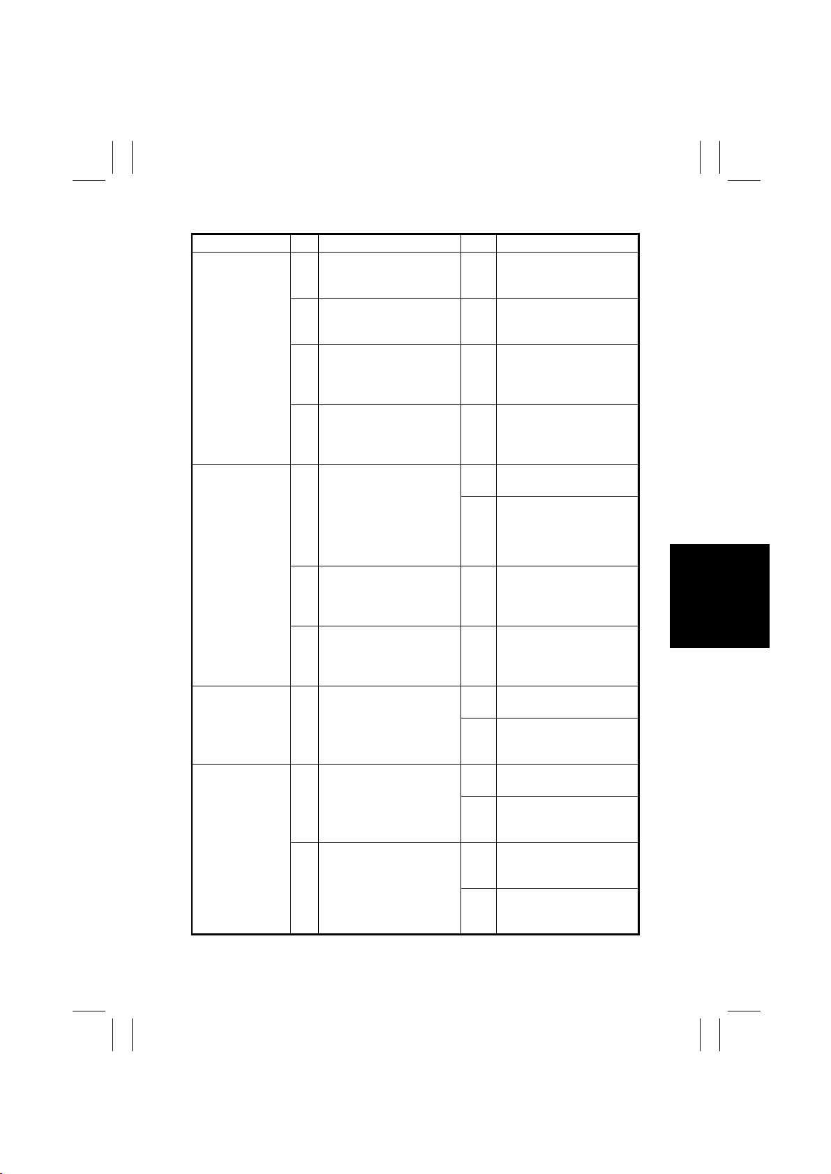
2. Make checks in numerical order of steps and, i f an item is checked okay, go to the next
step.
Patt ern 1
Step Check Item Result Action
1 Is ...? YES Do this.
2 Go to step 2 if it checks okay.
Pattern 2
Step Check Item Result Action
Is ...? YES Do this.
1
2
NO Check that.
Go to step 2 if i t
checks okay.
T-1
Page 5
FrameMaker Ver.5.5(PC) EP1054/EP1085/EP2030 TROUBLESHOOTING
98.05.15
2 I/O PORT CHECK
2-1. Controlled Parts Check Procedure
To al low the Tech. Rep . to easily and safely determine whether a particular c ontrolled part
is fully operational, this copier pro vides the follow ing provision: chec king of the data of the I/
O port on the board IC with the copier in the standby state (inc luding a misf eed, malfunction, and closure failure condition) allows the Tech. Rep. to determine whether a signal is
properly input to, and output from, a controlled part.
<Procedure>
1. When a paper misfeed or malfunction occurs, identify t he I/O port of the possibly defective cont rolled part by reviewing the text or I/ O port check list.
2. Select the I/O Check func tion of the Service mode and show on the Touch Panel the
status of the I/O port identified in step 1.
3. Check the input or output port data to determine whether the controlled part is opera tional and signals are properly input and output.
<Controlled Part Check Procedure by Changing Input P ort Data>
Example
When a paper misfeed occurs in the paper take-up section of the copier, 1st Dra wer Paper
Take-Up Sensor PC55 is considered to be res ponsible for it.
<Procedure>
1. Remove the sheet of paper misfed.
2. Fr om the I /O port che c k li st , i t is found that the H/L inpu t sig nal to P C55 i s sup pl ied fr om
PWB-A (IC4A) APA1.
3. Select the I/ O Chec k fu nc tio n fr om the S ervice mode me nu and, usin g th e P a per S elec t
key, show the status of PWB-A (IC4A) APA1 on the control panel.
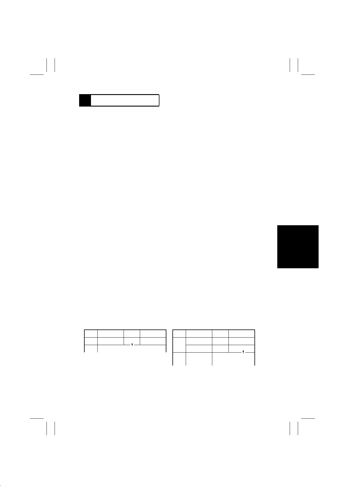
4. Check that the second LED from the right of the Exposure Level Display ligh ts up (sensor being unblocked).
Zoom Ratio Indicator
•
Multi-Copy Display
•
Exposure Level Display
•
5. Move the PC55 actuator to block the sensor .
6. Check at this time that the LED goes out.
ON: PC55 is faulty. OFF: PC55 is operational.
XAPA
4A
1234567 0
T-2
Page 6
2-2. Port Check List
Copier
Symbol Name
M1 PC Drive Motor P47 P4 1A OFF ON
M1 PC Drive Motor lock signal P67 P6
M2 Main Drive Motor P43 P4
M2 Main Drive Motor lock signal P66 P6
M3 Optical Section Cooling Fan Motor P43 P4
Optical Section Cooling Fan Motor
M3
T-3
lock signal
M4 Suction Fan Motor P43 P4
M5 Scanner Motor
M6 Lens Motor
M7 Mirror Motor
M8 T oner Replenishing Motor BPA5 BPA 4A OFF ON PJ5A-6A
M9 Cooling Fan Motor
M9 Cooling Fan Motor lock signal APC2 APC 4A
SL2
1st Drawer Paper Take-Up Solenoid
2nd Drawer Paper Take-Up Solenoid
SL3
✽
1st Drawer paper take-up LED on the Monitor Display lights up.
Port
Magnification
No.
Ratio Indic ator
P65 P6
P61 P6
P62
P61
P62
P61
P62
OUTO
BPA4 BPA 4A OFF ON PJ4A-9
BPA3
↑↑
↑↑
↑↑
↑↑
↑↑
OUT 5A OFF ON PJ20A-1
↑↑
Multi-Copy
Display
↑
↑
↑
↑
↑
↑
↑
Manual Exposure
Indicator
Operation Characteristics
ON OFF
When locked When turned PJ 11A-11A
OFF ON
When locked When turned PJ 11A-13A
OFF ON PJ22A-2
When locked When turned
OFF ON PJ5A-9A
OFF ON
ON OFF
OFF ON
OFF ON
ON OFF
OFF ON
When locked When turned
OFF ON PJ3A-2
CN/PJ
No.
PJ11A-12A
PJ11A-14A
PJ22A-3
PJ16A-3B
PJ16A-1B
PJ16A-2B
PJ20A-3
FrameMaker Ver.5.5(PC) EP1054/EP1085/EP2030 TROUBLESHOOTING
98.05.15
Page 7
FrameMaker Ver.5.5(PC) EP1054/EP1085/EP2030 TROUBLESHOOTING
98.05.15
No.
CN/PJ
PJ12A-4
When
blocked
PJ19A-2
When
blocked
PJ12A-3
When
blocked
When
5A
blocked
8A
PJ17A-
When
blocked
PJ17A-
PJ5A-6B
When
blocked
ON OFF
Operation Characteristics
Indicator
Manual Exposure
Display
Multi-Copy
Magnification
Ratio Indic ator
No.
Port
OFF ON PJ5A-3B
OFF ON PJ12A-5
↑↑
↑↑
PB0 PB 5A OFF ON PJ5A-2B
PB1
OFF ON PJ5A-2A
↑↑
When
When
unblocked
↑
PB2 PB 5A OFF OFF PJ5A-4B
When
unblocked
↑↑
unblocked
When
When
unblocked
↑
When
unblocked
unblocked
↑↑
↑↑
Symbol Name
Manual Feed Paper Take-Up Solenoid
(down)
Manual Feed Paper Take-Up Solenoid
(up)
SL51
SL51
SL61 Turnover/Exit Switching Soleno id PB3
Manual Feed Paper Take-Up
Clutch
CL1 Synchronizing Roller Clutch BPA0 BPA 4A OFF ON PJ5A-4A
CL2 Paper Transport Clutch BPA1
CL51
PC10 Left Door Detecting Sensor PA3 PA1
PC12 Duplex Vertical Transport Sensor PA2
PC30 2nd Paper Exit Sensor APB7 APB 4A
PC31 Manual Feed Paper Empty Sensor APC3 APC
PC53 1st Paper Exit Sensor APC5
PC51 Transport Roller Sensor APC7
T-4
Page 8
FrameMaker Ver.5.5(PC) EP1054/EP1085/EP2030 TROUBLESHOOTING
98.05.15
2A
No.
CN/PJ
PJ17A-
PJ4A-2
When
When
blocked
ON OFF
When
Operation Characteristics
Manual Exposure
Multi-Copy
unbloc ked
Indicator
Display
↑↑
When
blocked
When
When
unblocked
↑
5B
PJ3A-7
PJ17A-
When
blocked
unbloc ked
When
blocked
When
When
unblocked
7B
PJ17A-
PJ12A-2
blocked
unbloc ked
PJ22A-5
When
When
blocked
blocked
When
When
unblocked
unbloc ked
↑↑
PJ4A-6
PJ22A-8
When
blocked
When
unblocked
PJ3A-4
When
When
blocked
blocked
When
When
unblocked
unbloc ked
↑
Magnification
Port
Symbol Name
Ratio Indic ator
No.
APC6
Paper Leading Edge Det ecting
Sensor
PC54
PC55 1st Drawer Paper Take-Up Sensor APA1 APA
PC56 2nd Drawer Paper Take-Up Sensor PA5 PA1 5A
PC57 Right Door Detecting Sensor APA0 APA 4A
APB0 APB 4A
Scanner Reference Position
Sensor
PC69 2nd Drawer Set Sensor PA7 PA1 5A
PC81
PC86 Mirror Reference P osition sensor APB2
PC90 Lens Reference Position Sensor APB1 APB 4A
PC101 1st Drawer Paper Empty Sensor APA2 APA
PC102 2nd Drawer P aper Empty Sensor PA6 PA1 5A
T-5
Page 9
FrameMaker Ver.5.5(PC) EP1054/EP1085/EP2030 TROUBLESHOOTING
98.05.15
No.
CN/PJ
When
ON OFF
When
Operation Characteristics
Indicator
Manual Exposure
Display
Multi-Copy
Magnification
Ratio Indic ator
2B
PJ17A-
PJ18A-2
When
blocked
unblocked
↑
When
blocked
When
When
unbloc ked
When
blocked
When
(blinking)
unbloc ked
When
blocked
When
(blinking)
unbloc ked
↑↑
When
blocked
unbloc ked
↑↑
blocked
When
(blinking)
(blinking)
unbloc ked
No.
CN/PJ
upward PJ10A-1
downward PJ10A-2
ON OFF
OFF ON PJ10A-1
stop/
Operation Characteristics
Indicator
Manual Exposure
Display
Multi-Copy
↑↑
3rd Drawer paper take-up LED on the Monitor Display lights up.
✽
Magnification
Ratio Indic ator
downward
stop/upward
↑↑
↑↑
Port
Symbol Name
No.
Toner Hopper Home Position
PC111 Original Cover Detecti ng Sensor PA2 PA0
PA6 PA0 5A
APB6 APB 4A
Sensor
Original Size Detecting Sensor
PC112
PC113
FD2
Original Size Detecting Sensor
PA5
PC114
CD1
Original Size Detecting Sensor
PA7
PC115
FD3
Original Size Detecting Sensor
PA4 PA0 5A
CD2
PC116
PF-206, PF-112
Port
Symbol Name
No.
PA2
Main Tray Elevator Motor (downward)
M24 3rd Drawer Paper Lift-Up Motor P A0 PA 1A OFF ON PJ10A-3
M25 4th Drawer Paper Lift-Up Motor PA2
M26
M26 Main Tray Elevator Mot or (upward) PA3
T-6
Page 10
FrameMaker Ver.5.5(PC) EP1054/EP1085/EP2030 TROUBLESHOOTING
98.05.15
No.
CN/PJ
return PJ10A-3
PJ9A-9
PJ3A-3
PJ3A-4
PJ3A-5
PJ9A-5
PJ9A-12
When
When
When
When
When
blocked
blocked
blocked
blocked
When
blocked
blocked
PJ5A-2
PJ8A-9B
When
blocked
PJ5A-5
When
When
blocked
blocked
ON OFF
Operation Characteristics
Indicator
Manual Exposure
Display
Multi-Copy
Magnification
Ratio Indic ator
No.
Port
OFF ON PJ10A-6
stop/return transfer PJ10A-4
stop/transfer
↑
↑↑
↑↑
When
When
When
When
When
When
When
When
unblocked
unblocked
unblocked
unblocked
unblocked
unblocked
unblocked
↑
↑↑
↑
↑
When
unbloc ked
unbloc ked
↑↑
Symbol Name
M27 Paper Shift Motor (transfer) PA1
M28 Shift Gate Motor PB2 PB
M27 Paper Shift Motor (return) PA0
PC1 Shift Tray Paper Empty Sensor PD1 PD 1A
PC2 Main Tray Lower Position Sensor PC 1 PC 2A
PC3 Shifter Home Position Sensor PC0
PC4 Shift Return Position Sensor PD1 PD
PC5 Elevator Motor Pulse Sensor PF2 PF 1A
PC6 Shift Motor Pulse Sensor PD0 PD
SL41 3rd Drawer Lock Solenoid PA1 PA 2A OFF ON PJ6A-2
PC7 3rd Drawer Set Sensor PG2 PG
PC11 Lower Left Door Set Sensor PB1 PB 2A
PC13 Duple x Uni t Turnover Path sensor PB0
T-7
Page 11
FrameMaker Ver.5.5(PC) EP1054/EP1085/EP2030 TROUBLESHOOTING
98.05.15
No.
CN/PJ
PJ8A-9A
PJ8A-5A
When
When
blocked
blocked
PJ8A-2B
PJ8A-12B
When
blocked
PJ8A-2A
When
When
blocked
blocked
PJ9A-2
PJ8A-12A
When
blocked
PJ9A-12
When
When
blocked
When
blocked
PJ9A-5
PJ8A-9B
When
blocked
blocked
ON OFF
When
When
unblocked
Operation Characteristics
Indicator
Manual Exposure
Display
Multi-Copy
Magnification
Ratio Indic ator
No.
Port
unblocked
↑
When
When
When
When
When
When
When
unblocked
unblocked
unblocked
unblocked
unblocked
↑
↑
↑
unblocked
↑
↑
When
unblocked
unblocked
↑
↑
Symbol Name
PC17 Vertical Transport Sensor 3 PC3 PC 1A
PC20 3rd Drawer Paper Empty Sensor PC0 PC
PC21 3rd Drawer Paper Take-Up Sensor PE3 PE
PC22 V ertical Transport Sensor 4 PC2 PC
PC23 4th Drawer Paper Li ft-Up Sensor PF3 PF
PC24 4th Drawer Paper Empty Sensor PD0 PD
PC25 3rd Drawer Set Sensor PG2 PG
PC18 Lower Righ t Door Set Sensor PE2 PE
PC19 3rd Drawer Paper Lift-Up Sensor PG3 PG 1A
PC26 4th Draw er Set Sensor PF2 PF
T-8
Page 12
FrameMaker Ver.5.5(PC) EP1054/EP1085/EP2030 TROUBLESHOOTING
98.05.15
No.
CN/PJ
ON OFF
Operation Characteristics
Indicator
Manual Exposure
PJ9A-9
PJ4A-2
PJ3A-7
PJ8A-5B
When
When
blocked
When
unblocked
When
blocked
blocked
When
When
unblocked
unblocked
PJ3A-6
When
When
blocked
blocked
When
When
unbloc ked
unbloc ked
PJ9A-2
When
blocked
When
unblocked
Multi-Copy
Magnification
Port
Symbol Name
↑
↑
Display
Ratio Indic ator
No.
PC1 PC
PD1 PD
3rd Drawer Paper Lift-Up Motor
Pulse Senso r
4th Drawer Paper Li ft-Up Motor
Pulse Senso r
PC27
PC28
PC29 4th Drawer Paper Take-Up Sensor PB3 PB 2A
PC34 Shift Gate Position Sensor PC1 PC 1A
2A OFF ON PJ3A-2
↑
PC35 Lower Position Sensor PB3 PB 2A
UN21 Paper Descent Key PC2
PWB-E Main Tray Paper Empty Board PF3 PF 1A
T-9
Page 13
T-10
AD-11/PF-6D
Symbol Name
M31 Duplex Unit Drive Motor PB3 PB 1A OFF ON PJ6G-2
M31 Duplex Unit Drive Motor lock signal PE1 PE
CL31 Duplex Unit Paper Take-Up Clutch PA3 PA
SL31
Duplex Unit Gate Switching Solenoid
SL32 Duplex Unit Rear Finger Solenoid PH0
PC8
Duplex Gate Home Position Sensor
Front/Rear Edge Guide Plate Home
PC9
Position Sensor
PC14 Duplex Unit Trailing Sensor PC1
PC15 Duplex Unit Paper Empty Sensor PC2
Duplex Unit Pap er Take-Up
PC16
Sensor
Port
No.
PH1 PH
PE0 PE
PC3 PC
PC0
The Duplex U nit LED on the Monitor Display lights up.
✽
Magnification
Ratio Indic ator
↑↑
↑↑
↑↑
↑↑
Multi-Copy
Display
↑
↑
↑
↑
↑
Manual Exposure
Indicator
Operation Characteristics
ON OFF
When locked When turned
OFF ON PJ2G-7
OFF ON PJ3G-5
OFF ON PJ3G-7
When
unblocked
When
unblocked
When
unblocked
When
unblocked
When
unblocked
When
blocked
When
blocked
When
blocked
When
blocked
When
blocked
CN/PJ
PJ6G-1
PJ7G-2
PJ7G-5
PJ3G-2
PJ2G-4
PJ2G-9
No.
FrameMaker Ver.5.5(PC) EP1054/EP1085/EP2030 TROUBLESHOOTING
98.05.15
Page 14
FrameMaker Ver.5.5(PC) EP1054/EP1085/EP2030 TROUBLESHOOTING
98.05.15
3 PAPER TRANSPORT FAILURE
3-1. Paper Misfeed
When a paper misfeed occurs in the copier, the corresponding Misfeed Location Mon itor
LED on the control panel blink s to let the user know where the misf eed has occurred. If an
LED lights up steadily, it indicates that there might be a sheet of paper present at that particular loc ation in the copier. If a paper misfeed occurs very frequently, carry out the nec essary troubleshooting proced ures according to the location of th e misfeed.
Blinking
LED
Copier take-up and vertical transport T-15~T-17
➁
Paper Feed Cabinet take-up and vertical trans-
➂
port
Bypass port T-22, T-23
➀
Transport/Separator T-24, T-25
➄
Fusing/Exit T-26, T-27
➅
➆ ➈
When option is installed
✽
Duplex Unit vertical transport T-28~T-30
Duplex Unit storage T-28~T-30
➇
Duplex Unit take-up T-31, T-32
➂
Sorter/Staple Sorter —
➉
Automatic/Duple xing Document Feeder —
➃
Blinking
Light
Steady
Light
1139T025AA
Misfeed Loc ation Ref. Page
There is a misf ee d at
that location.
There might be a
sheet of paper
stopped at that location.
T-1 8~ T-2 1
✽
✽
✽
✽
✽
✽
T-11
Page 15
FrameMaker Ver.5.5(PC) EP1054/EP1085/EP2030 TROUBLESHOOTING
98.05.15
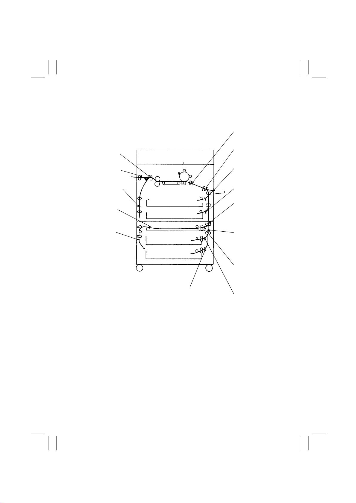
The paper misfeed, including a sheet of paper that is likely to be present, in the copier as
well as in t he paper feeder options is detected by the following sensors.
When options ar e i nstalled
✽
Paper Leading
Edge Detecting
Sensor PC54
Transport Roller
1st Paper Exit
Sensor PC53
2nd Paper Exit
✽
Sensor PC30
Duplex Vertical
✽
Transport
Sensor PC12
Duplex Uni t
✽
Trailing Sensor
PC14
Duplex Uni t
✽
Tu rnover Path
Sensor PC13
Sensor PC51
1st Drawer
Paper Take-Up
Sensor PC55
2nd Drawer
Paper Take-Up
Sensor PC56
Vertical
✽
Transport
Sensor 3
PC17
Vertical
✽
Transport
Sensor 4
PC22
✽
T-12
4425T201AA
4th Drawer
Paper Take-Up
Sensor PC29
Duplex Unit
✽
Paper Take-Up
Sensor PC16
3rd Drawer
✽
Paper Take-Up
Sensor PC21
Page 16
FrameMaker Ver.5.5(PC) EP1054/EP1085/EP2030 TROUBLESHOOTING
98.05.15
3-2. Misfeed Detected Types and Detection Timings
The foll ow ing tab le l ist s the t ypes of misfeed detection classifie d b y th e mis f eed locat ions
•
and their corre sponding detection timings.
Note
For the misfeed detection types and detection timings in the options, see the Service Manual for the options.
<Paper Take-up Misfeed>
Type Detection Timing
Pape r take-up failure
detection
Paper take-up trailing
edge detection
Leading edge detection
by Transport Roller Sensor PC51
1st Drawer Paper Take-Up Sensor PC55 is not blocked (L) after
the lapse of approx. 2.4 seconds after 1st Drawer Paper TakeUp Solenoid SL 2 has been energized during the third paper
take-up retry sequence.
2nd Draw er Paper T ake-Up Sensor P C56 i s n ot b lo c k e d (L) afte r
the lapse of approx. 2.4 seconds after 2nd Drawer Paper TakeUp Solenoid SL 3 has been energized during the third paper
take-up retry sequence.
PC55 is not unb l ocked (H) after the lapse of T seconds (which
varies for paper sizes) after it has been blocked (L).
PC56 is not unb l ocked (H) after the lapse of T seconds (which
varies for paper sizes) after it has been blocked (L).
PC51 is not b l ocked (L) after the lapse of approx. 1.7 seconds
after PC55 has been blocked (L).
PC51 is not b l ocked (L) after the lapse of approx. 2.5 seconds
after PC56 has been blocked (L).
<Multi-Bypass Misfeed>
Type Detection Timing
Pape r take-up failure
detection
Leading edge detection
by Paper Leading Edge
Detecting Sensor PC54
<Transport/Separator Misfeed>
Type Detection Timing
Trailing edge detection
by Transport Roller Sensor PC51
Leading edge detection
by Paper Leading Edge
Detecting Sensor PC54
Trailing edge detection
by PC54
PC51 is not b l ocked (L) after the lapse of approx. 2.7 seconds
after Manual Feed Paper Take-Up Clutch CL51 has been energized during t he third paper take-up retry sequence.
PC54 is not b l ocked (L) after the lapse of approx. 2.5 seconds
after Paper Transport Clutch CL2 has been energized.
PC51 is not unb l ocked (H) after the lapse of T seconds (which
varies for paper sizes) after the TRON signal has been input.
PC54 is not b l ocked (L) after the lapse of approx. 1.5 seconds
after PC51 has been blocked (L).
PC54 is not unb l ocked (H) after the lapse of approx. 1.6 seconds after PC51 has been unblocked (H) .
T-13
Page 17
FrameMaker Ver.5.5(PC) EP1054/EP1085/EP2030 TROUBLESHOOTING
98.05.15
<Fusing/Exit Misfeed>
Type Detection Timing
Leading edge detection
by 1st P aper Exit Sensor
PC53
Trailing edge detection
by PC53
Leading edge detection
by 2nd Paper Exit Sensor PC30
Trailing edge detection
by PC30
PC53 is not unb l ocked (H) after the lapse of approx. 4.5 seconds after the TRON signal has been input.
PC53 is not b l ocked (L) after the lapse of approx. 3.7 seconds
after PC54 has bee n unblocked (H).
PC30 is not b l ocked (L) after the lapse of approx. 2 seconds
after PC53 has bee n unblocked (H).
PC30 is not unb l ocked (H) after the lapse of approx. 2 seconds
after PC53 has been blocked (L).
T-14
Page 18
FrameMaker Ver.5.5(PC) EP1054/EP1085/EP2030 TROUBLESHOOTING
98.05.15
3-3. Misfeed Clearing Procedures
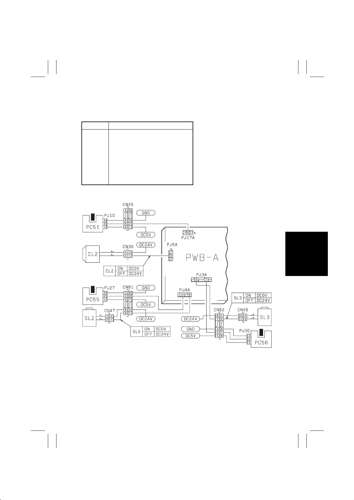
(1) Copier Take-Up Misfeed
Symbol Name
PC51
PC55
PC56
SL2
SL3
CL2
PWB-A
Transport Roller Sensor
1st Dra w er Paper Take-Up Sensor
2nd Drawer Paper Take-Up Sensor
(23 cpm Copier)
1st Dra w er Paper Take-Up Solenoid
2nd Drawer Paper Take-Up Solenoid
(23 cpm Copier)
Pape r Transport Clutch
Master Board
T-15
1174C01TAA
Page 19
FrameMaker Ver.5.5(PC) EP1054/EP1085/EP2030 TROUBLESHOOTING
98.05.15
Copier Take-Up Misfeed Clearing Procedure
Symptom
Paper is not
•
taken up at all.
Paper is st ation-
•
ary before the
Paper Take-Up
Sensor.
Continued on next page
Step
1
2
3
4
5
6
7
8
9
Check Item
Does the pap er being used
meet product specifications?
Is the paper curled, waved,
or damp? YES
Are the Separ ator Fingers
on both s ides of t he D rawer
in position?
Are the Separ ator Fingers
deformed?
Is the Trailing Edge Stop or
Edge Guide in good position?
Are the Paper Lifting
Springs positioned correctly?
Are the Paper Take-Up
Rolls deformed, worn, or
dirty with paper dust?
Is a signal being output
from PWB-A to the Paper
Take-Up Solenoid?
Does the voltage across
✽
PJ4A-9 (1st Drawer) or
PJ3A-2 (2nd Dra w er) on
PWB-A and GND cha nge
from DC24V to DC0V
when th e St art Key is
pressed?
Is the Clutch Spr ing
deformed or worn?
Result
NO
NO
YES
NO
NO
YES
YES
NO
YES
Instruct the user to use the
paper that meets product
specifications.
Change the paper.
Instruct the user in how to
store the paper.
Instruct the user to l oad the
paper so that it res ts under
the Fingers.
Replace the Fing e r s.
Instruct the user in how to
position the Edge Stop or
Guide.
Change the position of the
Springs or add one as necessary.
Clean or replace the Paper
Take- Up Rolls.
Adjust the Solenoid stroke.
Check the Solenoid.
Replace PWB-A.
Replace the Clut c h Spring.
Action
T-16
Page 20
FrameMaker Ver.5.5(PC) EP1054/EP1085/EP2030 TROUBLESHOOTING
98.05.15
Symptom
Paper is st ation-
•
ary before the
Vertical Transport Roller.
Paper is st ation-
•
ary at the Vertical Transport
Roller.
Paper is
•
stationary near
the Transport
Roller.
Step
10
11
12
13
14
15
Check Item
Check 1st/2nd Drawer
Pape r Take-Up Sensor
(PC55/PC56). See p.T-2.
PC55: PWB-A ( IC 4A) APA1
PC56: PWB-A ( IC 5A) PA5
Are the Vertical Transport
Rollers deformed, worn, or
dirty with paper dust?
Are the Paper Take-Up
Guide Plate and Vertical
Transport Guide Plate dirty
or defo rmed?
Is a signal being output
from PWB-A to the Clutch?
Does the voltage across
✽
PJ5A-2A on PWB- A and
GND change from
DC24V to DC0V when
the Start Key is pressed?
Check Transport Roller
Sensor PC51. See p. T-2
(PWB-A (IC4A) APC7).
Are the Transport Rollers
deformed, worn, or dirty
with paper dust?
Result
YES Replace PW B-A.
Check the Ac tuator for
operation.
NO
Check the Paper Take-Up
Sensor.
Clean or replace the
YES
V e rtical Transport Rollers.
Clean, correct, or replace
the Guide Plate.
YES
YES Check the Clutch.
Replace PWB-A.
NO
YES
Replace or check the PWB-A.
Check the Ac tuator for
NO
operation.
Check PC51.
Clean or replace the
YES
Transport Rollers.
Action
T-17
Page 21
FrameMaker Ver.5.5(PC) EP1054/EP1085/EP2030 TROUBLESHOOTING
98.05.15
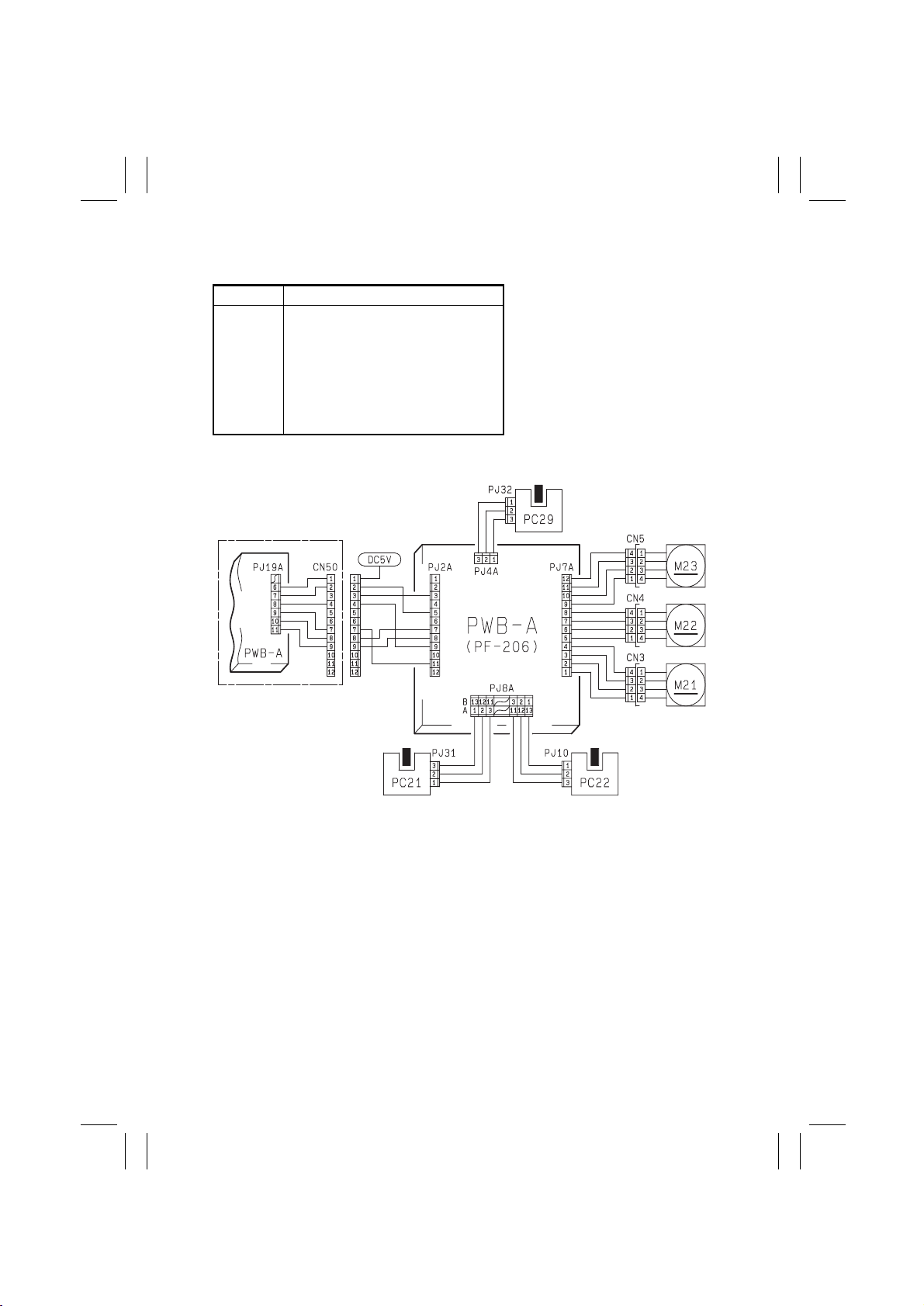
(2) PF-206 Tak e-Up Misfeed (23 cpm Copier)
Symbol Name
PC21
PC22
PC29
M21
M22
M23
PWB-A
PWB-A
3rd Drawer Paper Take-Up Sensor
Vertical Transport Sensor 4
4th Drawer Paper Take-Up Sensor
Vertical Transport Motor
3rd Drawer Paper Take-Up Motor
4th Drawer Paper Take-Up Motor
23 cpm Copier Master Board
PF-206 Master Board
T-18
1174C02TAA
Page 22
FrameMaker Ver.5.5(PC) EP1054/EP1085/EP2030 TROUBLESHOOTING
98.05.15
Pape r Feed Cabinet Take-Up Misfeed Clearing Procedure
Symptom
Paper is not
•
taken up at all.
Paper is st ation-
•
ary before the
Paper Take-Up
Sensor.
Paper is
•
stationary
before the
Vertical Transport Rollers.
Paper is
•
stationary near
Vertical Transport Sensor 4
PC22.
Paper is
•
stationary
before the
copier.
Step
1
2
3
4
5
6
7
8
9
10
Check Item
Does the pap er being used
meet product specifications?
Is the paper curled, waved,
or damp? YES
Is the P a per Take-Up Motor
turning when the Start Key
is pressed?
Is the Paper Take-Up Roll
or Separa tor Roll deformed,
worn, or dirty with paper
dust?
Check 3rd/4th Drawer
Pape r Take-Up Sensor
(PC21/PC29). See p. T-2.
PC21: (PF-206) PWB-A
IC1A PE3.
PC29: (PF-206) PWB-A
IC2A PB3.
Is Vertical Transport Motor
M21 turning when the Start
Ke y is pressed?
Is the Vertical Transport
Roller or Guide Plate
deformed, worn, or dirty
with paper dust?
Check Vertical Transport
Sensor 4 PC22.
See p. T-2 (PF-206) PWB-A
IC1A PC2.
Check Vertical Transport
Sensor 4 PC22.
See p. T-2 (PF-206) PWB-A
IC1A PC2.
Is the Vertical Transport
Roller or Guide Plate
deformed, worn, or dirty
with paper dust?
Result
NO
NO
YES
YES
NO
NO
YES
YES
NO
YES
NO
YES
NO
Instruct the user to use the
paper that meets product
specifications.
Change the paper.
Instruct the user in how to
store the paper.
Check for possible overload.
Replace PWB-A or PF-206
PWB-A.
Check the Motor.
Clean or replace the Paper
Take-Up or Separator Roll.
Replace PWB-A or P F- 206
PWB-A.
Check the Ac tuator for
operation.
Check the Paper Take-Up
Sensor.
Check for possible overload.
Replace PWB-A or PF-206
PWB-A.
Check the Motor.
Clean or replace the
V e rtical Transport Roller or
Guide Plate.
Replace PWB-A or P F- 206
PWB-A.
Check the Ac tuator for
operation and check the
Sensor.
Replace PWB-A or P F- 206
PWB-A.
Check the Ac tuator for
operation and check the
Sensor.
Clean or replace the Vertical Transport Roller or
Guide Plate.
Check the Paper Feed Cabinet for po sitive connection
to the co pi e r.
Action
T-19
Page 23
FrameMaker Ver.5.5(PC) EP1054/EP1085/EP2030 TROUBLESHOOTING
98.05.15
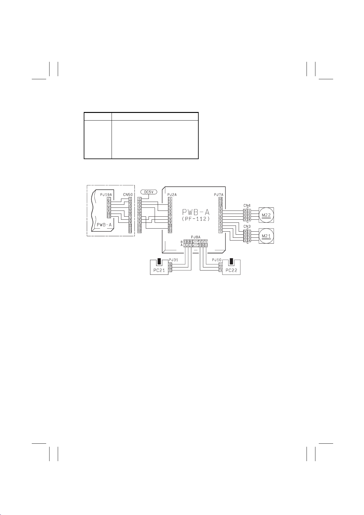
(3) PF-112 Tak e-Up Misfeed (23 cpm Copier)
Symbol Name
PC21
PC22
M21
M22
PWB-A
PWB-A
3rd Drawer Paper Take-Up Sensor
Vertical Transport Sensor 4
Vertical Transport Motor
3rd Drawer Paper Take-Up Motor
23 cpm Copier Master Board
PF-112 Master Board
T-20
1174C03TAA
Page 24

FrameMaker Ver.5.5(PC) EP1054/EP1085/EP2030 TROUBLESHOOTING
98.05.15
Pape r Feed Cabinet Take-Up Misfeed Clearing Procedure
Symptom
Paper is not
•
taken up at all.
Paper is st ation-
•
ary before the
Paper Take-Up
Sensor.
Paper is st ation-
•
ary before the
Vertical Transport
Rollers.
Paper is
•
stationary near
Vertical Transport Sensor 4
PC22.
Paper is
•
stationary
before the
copier.
Step
1
2
3
4
5
6
7
8
9
10
Check Item
Does the pap er being used
meet product specifications?
Is the paper curled, waved,
or damp? YES
Is the P a per Take-Up Motor
turning when the Start Key
is pressed?
Is the Paper Take-Up Roll
or Separa tor Roll deformed,
worn, or dirty with paper
dust?
Check 3rd Drawer Paper
Take-Up Sensor PC21 .
See p. T-2.
PC21: (PF-112) PWB-A
IC1A PE3.
Is Vertical Transport Motor
M21 turning when the Start
Ke y is pressed?
Is the Vertical Transport
Roller or Guide Plate
deformed, worn, or dirty
with paper dust?
Check Vertical Transport
Sensor 4 PC22.
See p. T-2 (PF-112) PWB-A
IC1A PC2.
Check Vertical Transport
Sensor 4 PC22.
See p. T-2 (PF-112) PWB-A
IC1A PC2.
Is the Vertical Transport
Roller or Guide Plate
deformed, worn, or dirty
with paper dust?
Result
NO
NO
YES
YES
NO
NO
YES
YES
NO
YES
NO
YES
NO
Instruct the user to use the
paper that meets product
specifications.
Change the paper.
Instruct the user in how to
store the paper.
Check for possible overload.
Replace PWB-A or PF-112
PWB-A.
Check the Motor.
Clean or replace the Paper
Take-Up or Separator Roll.
Replace PWB-A or P F- 112
PWB-A.
Check the Ac tuator for
operation.
Check the Paper Take-Up
Sensor.
Check for possible overload.
Replace PWB-A or PF-112
PWB-A.
Check the Motor.
Clean or replace the
V e rtical Transport Roller or
Guide Plate.
Replace PWB-A or P F- 112
PWB-A.
Check the Ac tuator for
operation and check the
Sensor.
Replace PWB-A or P F- 112
PWB-A.
Check the Ac tuator for
operation and check the
Sensor.
Clean or replace the Vertical Transport Roller or
Guide Plate.
Check the Paper Feed Cabinet for po sitive connection
to the co pi e r.
Action
T-21
Page 25

FrameMaker Ver.5.5(PC) EP1054/EP1085/EP2030 TROUBLESHOOTING
98.05.15
(4) Bypass Port Misfeed
Symbol Name
PC31
PC54
SL51
CL2
CL51
PWB-A
Manual Feed Paper Empty Sensor
Pape r Leading Edge Detecting Sensor
Manual F eed Paper Take-Up Solenoid
Pape r Transport Clutch
Manual Feed Paper Take-Up Clutch
Master Board
T-22
1174C24TAB
Page 26

FrameMaker Ver.5.5(PC) EP1054/EP1085/EP2030 TROUBLESHOOTING
98.05.15
Bypass Port Misfeed Clearing Procedure
Symptom
Paper is not
•
detected.
Paper is not
•
taken up at all. 2
Paper is
•
stationary near
the Transport
Roller.
Step
1
3
4
5
6
7
8
9
10
Check Item
Check Manual Feed Paper
Empty Sensor PC31. See
p. T-2 (PWB-A (IC4A) APC
3).
Does the paper being used
meet product specifications?
Is the paper curled, waved,
or damp? YES
Are the Paper Take-Up
Rolls pressed against the
paper stack when the Start
Ke y is pressed?
Does the voltage across
✽
PJ5A-2B on PWB-A and
GND change from
DC24V to DC0V when
the Start Key is pressed?
Does the voltage across
PJ5A-4B on PWB-A and
GND change from DC24V
to DC0V when the Start
Ke y is pressed?
Is the Pressure Pad or
Guide Plate deformed or
dirty?
Are the Paper Take-Up
Rolls deform ed, wor n, or
dirty with paper dust?
Check P aper Leading Edg e
Detecting Sensor PC54.
See p. T-2 (PWB-A (IC4A)
APC6).
Does the voltage across
PJ5A-2A on PWB-A and
GND change from DC24V
to DC0V when the Start
Ke y is pressed?
Is the Tr ansport Roller or
Guide Plate of the copier
deformed, worn, or dirty
with paper dust?
Result
YES Replace PWB-A.
NO
NO
YES
NO
YES Check the C l utch.
NO
YES
YES
NO
YES Check the C l utch.
NO
YES
Check the operation of the
actuator of PC31. If it operates properly, replace
PC31.
Instruct the user to use the
paper that meets product
specifications.
Change the paper.
Instruct the user in how to
store the paper.
Adjust the stroke of the
Solenoid.
Check the Solenoid .
Replace PWB-A.
Replace PWB-A.
Clean or replace the Pressure Pad or Guide Plate.
Clean or replace the Paper
Take-Up Rolls.
Check the Actuator for
operation.
Check PC54.
Replace PWB-A.
Clean or replace the Vertical Transport Roller or
Guide Plate.
Action
T-23
Page 27

FrameMaker Ver.5.5(PC) EP1054/EP1085/EP2030 TROUBLESHOOTING
98.05.15
(5) T ransport/Separator Misfeed
Symbol Name
PC51
PC54
CL1
M4
PWB-A
Transport Roller Sensor
Pape r Leading Edge Detecting Sensor
Synchronizi ng R oller Clutch
Suction Fan Motor
Master Board
T-24
1174C05TAA
Page 28

FrameMaker Ver.5.5(PC) EP1054/EP1085/EP2030 TROUBLESHOOTING
98.05.15
Transport/Separator Misfeed Clearing Procedure
Symptom
Paper is st ation-
•
ary before the
Synchronizing
Roller.
Paper is st ation-
•
ary near the PC
Drum.
Paper is wedged
•
at the Paper Separator Fi ng ers.
Paper is st ation-
•
ary before the
Suction Belts.
Step
1
2
3
4
5
6
7
8
9
10
11
12
13
14
Check Item
Is the paper curled, waved,
or damp? YES
Check Paper Leading Edge
Detecting Sensor PC54
See p. T-2 (PWB-A (IC4A)
APC6).
Check Synchronizing Roller
Clutch CL1.
Does the voltage across
✽
PJ5A-4A on PWB-A and
GND change from DC24V
to DC0V after the Start
Key has been pressed?
Is a given length of loop
formed before the Synchr o-
nizing Roller?
Is the Pre-Image Transfer
Guide Plate deformed or dirty?
Is the Corona Unit Cleaning
Lever (Lower) in correct
position?
Are the Image Transfer/
Paper Separator Corona
Wires deterior ated or dirty?
Are the Paper Guides
deformed or dirty?
Are the Synchronizing Roll ers deformed, worn, or dirty
with paper dust?
Are the Paper Separator
Fingers deformed or dirty? YES
Check Transport Roller
Sensor PC51. See p. T-2
(PWB-A (IC4A) APC7).
Check Paper Leading Edge
Detecting Sensor PC54.
See p. T-2
(PWB-A (IC4A) APC6).
Do the Suction Belts turn
properly?
Check Suction Fan Motor M4.
Does the voltage across
✽
PJ5A-9A on PWB- A and
GND change from
DC24V to DC0V when
the Start Key is pressed?
Result
Change the paper.
Instruct the user in how to
store the paper.
YES Replace PW B-A.
Check the Ac tuator for
NO
operation.
Check PC54.
YES Check the Clutch.
Replace PWB-A.
NO
Adjust the loop length or
NO
clean or replace the Transport Rollers.
Correct or clean the Guide
YES
Plate.
Place the Lever in position.
NO
Clean or replace the Wires.
YES
Clean or replace the Paper
YES
Guides.
Clean or replace the Syn-
YES
chronizing Rollers.
Correct or clean, or replace,
the Paper Separator Fingers.
Check the Ac tuator for
NO
operation.
Check PC51.
YES Replace PW B-A.
Check the Ac tuator for
NO
operation.
Check PC54.
Check the Belts and Drive
NO
Gear.
Check the DC24V line.
YES
Check M4.
Replace PWB-A.
NO
Action
T-25
Page 29

FrameMaker Ver.5.5(PC) EP1054/EP1085/EP2030 TROUBLESHOOTING
98.05.15
(6) Fusing/Exit Misfeed
Symbol Name
PC53
PC30
PC54
M4
PWB-A
1st Paper Exit Sensor
2nd Paper Exit Sensor
Pape r Leading Edge Detecting Sensor
Suction Fan Motor
Master Board
T-26
1174C06TAA
Page 30

FrameMaker Ver.5.5(PC) EP1054/EP1085/EP2030 TROUBLESHOOTING
98.05.15
Fusing/Exi t Misfeed Clearing Procedure
Symptom
Paper is st ation-
•
ary before the
Fusing Roller.
The leading
•
edge of the
paper is
stationary near
the Fusing
Roller.
Paper is
•
stationary afte r
the Paper Exit
Roller/Rolls.
Step
1
2
3
4
5
6
7
8
9
Check Item
Is the paper curled, waved,
or damp? YES
Is the Guide Plate di rty with
toner? YES
Do the Suction Belts turn
properly?
Check Suction Fan Motor
M4.
Does the voltage across
✽
PJ5A-9A on PWB- A and
GND change from
DC24V to DC0V when
the Start Key is pressed?
Are the Fusing Rollers
scratched or dirty? Or, has
the replacement time
arrived for the Rollers?
Are the Paper Separator
Fingers dirty with toner or
worn? Are their edges
damaged?
Is the Oil Roller dirty? Or,
has the re p l acement ti m e
arrived for the Roller?
Check 1st/2nd Paper Exit
Sensor (PC53/PC30). See
p. T-2.
PC53: PWB-A ( IC 4A)
APC5
PC30: PWB-A ( IC 4A) A PB7
Check Paper Leading Edge
Detecting Sensor PC54.
See p. T-2 (PWB-A (IC4A)
APC6).
Result
NO
YES
NO
YES
YES
YES
NO
YES Replace PW B-A.
NO
Change the paper.
Instruct the user in how to
store the paper.
Clean th e G u i d e Pl a t e.
Check for possible
scattering of toner.
Check the Belts and Drive
Gear.
Check the DC24V line.
Check M4.
Replace PWB-A.
Clean or replace the
Rollers.
Clean or replace the
Fingers.
Clean or replace the Roller.
Check the Ac tuator for
operation.
Check PC53 or PC30, or
both.
Check the Ac tuator for
operation.
Check PC54.
Action
T-27
Page 31

FrameMaker Ver.5.5(PC) EP1054/EP1085/EP2030 TROUBLESHOOTING
98.05.15
(7) Duplex Uni t Vertical Transport/Storage Misfeed (23 cpm Copier)
Symbol Name
PC12
PC13
PC14
PC15
PC53
SL31
SL61
M31
PWB-A
PWB-A
PWB-G
Duplex Vertical Transport Sensor
Duplex Unit Tur nover Path Sensor
Duplex Unit Trailing Sensor
Duplex Unit Paper Empty Sensor
1st Paper Exit Sensor
Duplex Unit Gate Switching Solenoid
Turnover/Exit Switching Solenoid
Duplex Unit Drive Motor
23 cpm Copier Master Board
Master Board of PF-206/PF112/PF-6D
Duplex Unit Master Board
T-28
1174C07TAB
Page 32

FrameMaker Ver.5.5(PC) EP1054/EP1085/EP2030 TROUBLESHOOTING
98.05.15
Duplex Unit Vertical Transport Misfeed C l eari ng Procedure
Symptom
Paper is st ation-
•
ary near the Exit
Section.
Paper is
•
stationary near
the Vertical
Transport Section of the
Duplex Unit.
Paper is st ation-
•
ary near the
Turnover Sec tion.
Continued on next page
Step
1
2
3
4
5
6
7
8
Check Item
Is the paper curled, waved,
or damp? YES
Does the voltage across
PJ12A-5 on PWB-A and
GND change from DC24V
to DC0V after the Start Key
has been pressed?
Are the Turnover/Exi t
Switching Plate and Upper
and Lower Guide Plates
deformed or dirty?
Is drive b eing tran smitt ed to
the V ertical Transport Roller
of the Duple x Unit? (Is
Duplex Unit Drive Motor
M31 turning after t he Start
Ke y has been pressed? )
Check Duplex Vertical
Transport Sensor PC12.
See p. T-2 (PWB-A (IC5A)
PA2) .
Check 1st Paper Exit Sensor PC53. See p. T-2
(PWB-A (IC4A) APC5).
Are the P addle Roller, Slip
Roller/Rolls, and Rolls B
Release Le ver deformed,
worn, or dirty with paper
dust?
Check Duplex Unit T urnove r
Pat h Sensor PC13. See p.
T -2 (PF- 206/PF-112/PF-6D)
PWB-A IC2 A PB 0 .
Result
YES
NO
YES
NO
NO
YES Replace PW B-A.
NO
YES
NO
YES
NO
Change the paper.
Instruct the user in how to
store the paper.
Adjust the stroke of the
Solenoid or check the
Solenoid.
Replace PWB-A.
Clean or replace the Plates.
Check for possible
overload.
Check the Duplex Un it drive
coupling or replace PWB-A
of PF-206/PF-112/PF-6D,
PWB-G, and/or M31.
Check the Ac tuator for
operation.
Check PC12.
Check the Ac tuator for
operation.
Check PC53.
Clean or replace the Roller
and/or Roll.
Check the Releas e Lever
mechanism.
Check th e drive coupl ing
from the Duplex Unit.
Replace PWB-A of PF - 20 6 /
PF-112/PF-6D.
Check the Ac tuator for
operation and PC13.
Action
T-29
Page 33

FrameMaker Ver.5.5(PC) EP1054/EP1085/EP2030 TROUBLESHOOTING
98.05.15
Symptom
The leading
•
edge of the
paper is
stationary inside
the Duplex Unit.
Paper is st ation-
•
ary near the
take-up port of
the Duplex Unit.
Step
9
10
11
12
Check Item
Is the Paper Guide Mylar
deformed or dirty?
Does the Gate Switching
Plate operate properly?
(Is Duplex Unit Gate
Switching Solenoid SL31
energized for a paper
length of 300 mm or
longer?)
Does the voltage across
✽
PJ3G-5 on PWB-G and
GND change from
DC24V to DC0V af ter th e
Start Key has been
pressed?
Check Duplex Unit Trailing
Sensor PC14. See p. T-2.
(AD-11) PWB- G IC1G PC1.
Check Duplex Unit Pa per
Empty Sensor PC15. See
p. T-2.
(AD-11) PWB- G IC1G PC2.
Result
YES Clean or replace the Mylar.
Check the Mylar moving
NO
mechanism.
Adjust the stroke of the
YES
Solenoid or check the Solenoid.
Replace PWB-G or PWB-A
of PF-206/PF-112/PF-6D.
NO
Check the Ac tuator for
YES
operation and PC14.
Replace PWB-G or PWB-A
NO
of PF-206/PF-112/PF-6D.
Check the Ac tuator for
YES
operation and PC15.
Replace PWB-G or PWB-A
NO
of PF-206/PF-112/PF-6D.
Action
T-30
Page 34

FrameMaker Ver.5.5(PC) EP1054/EP1085/EP2030 TROUBLESHOOTING
98.05.15
(8) Duplex Unit Take-Up Misfeed (23 cpm Copier)
Symbol Name
PC16
PC17
SL33
CL31
M21
PWB-A
PWB-G
Duplex Unit Paper Take-Up Sensor
Vertical Transport Sensor 3
Duplex Unit Pick-Up Solenoid
Duplex Unit Pa per Take-Up Clutch
Vertical Transport Motor
Master Board of
PF-206/PF-112/PF-6D
Duplex Unit Master Board
T-31
1174C08TAA
Page 35

FrameMaker Ver.5.5(PC) EP1054/EP1085/EP2030 TROUBLESHOOTING
98.05.15
Duplex Unit Take-Up Misfeed Clearing Procedure
Symptom
Paper is not
•
taken up at all. 1
Paper is
•
stationary near
the Vertical
Transport
Section.
Step
2
3
4
5
6
7
8
Check Item
Is the paper curled, waved,
or damp? YES
Is Duplex Unit Pick-Up Solenoid
SL33 energized when paper
take-up is about to occur?
Slide out the Duplex Unit and
✽
remove the PWB Cover.
Then, slide the Duplex Unit
back into the copier. D oes the
voltage across PJ2G-12 on
PWB-G and GND change
from DC24V to DC0V when
the Start Key is pressed in the
above condition?
Is Duplex Unit Paper Take-Up
Clutch CL31 energized when a
copy is taken up and fed into the
copier from the Duplex Unit?
Slide out the Duplex Unit and
✽
remove the PWB Cover.
Then, slide the Duplex Unit
back into the copier. D oes the
voltage across PJ2G-7 on
PWB-G and GND change
from DC24V to DC0V when
the Start Key is pressed in the
above condition?
Are the Take-Up Roll, Feed
Roll, and Separator Roll
deformed, worn, or dirty
with paper dust?
Is Vertical Transport Motor
M21 turning when a copy is
taken up and fed int o the
copier from the Dupl ex
Unit?
Are the Vertical Transport
Rollers and Guide Plate
deformed, worn, or dirty
with paper dust?
Check Duplex Unit Pa per
Take-Up Sensor PC16 .
(AD-11) PWB- G IC1G PC0.
Check Vertical Transport
Sensor 3 PC17.
See p. T-2
(PF-206/PF-112/PF-6D)
PWB-A IC1 A PC3 .
Result
Change the paper.
Instruct the user in how to
store the paper.
Adjust the stroke of the
YES
Solenoid or check the pickup mechanism.
Replace PWB-G or PWB-A
of PF-206/PF-112/PF-6D.
NO
YES Check the Clutch.
Replace PWB-G or PWB-A
of PF-206/PF-112/PF-6D.
NO
Clean or replace the Rolls.
YES
Check for possible overload.
Check the Duplex Unit drive
NO
coupling, or replace PWB-A
of PF-206/PF-112/PF-6D,
PWB-G, and/or M21.
Clean or replace the Vertical Transport Rollers and
YES
Guide Plate.
Check the Ac tuator for
NO
operation.
Check PC16.
Replace PWB-G or PWB-A
YES
of PF-206/PF-112/PF-6D.
Check the Ac tuator for
NO
operation.
Check PC17.
Action
T-32
Page 36

FrameMaker Ver.5.5(PC) EP1054/EP1085/EP2030 TROUBLESHOOTING
98.05.15
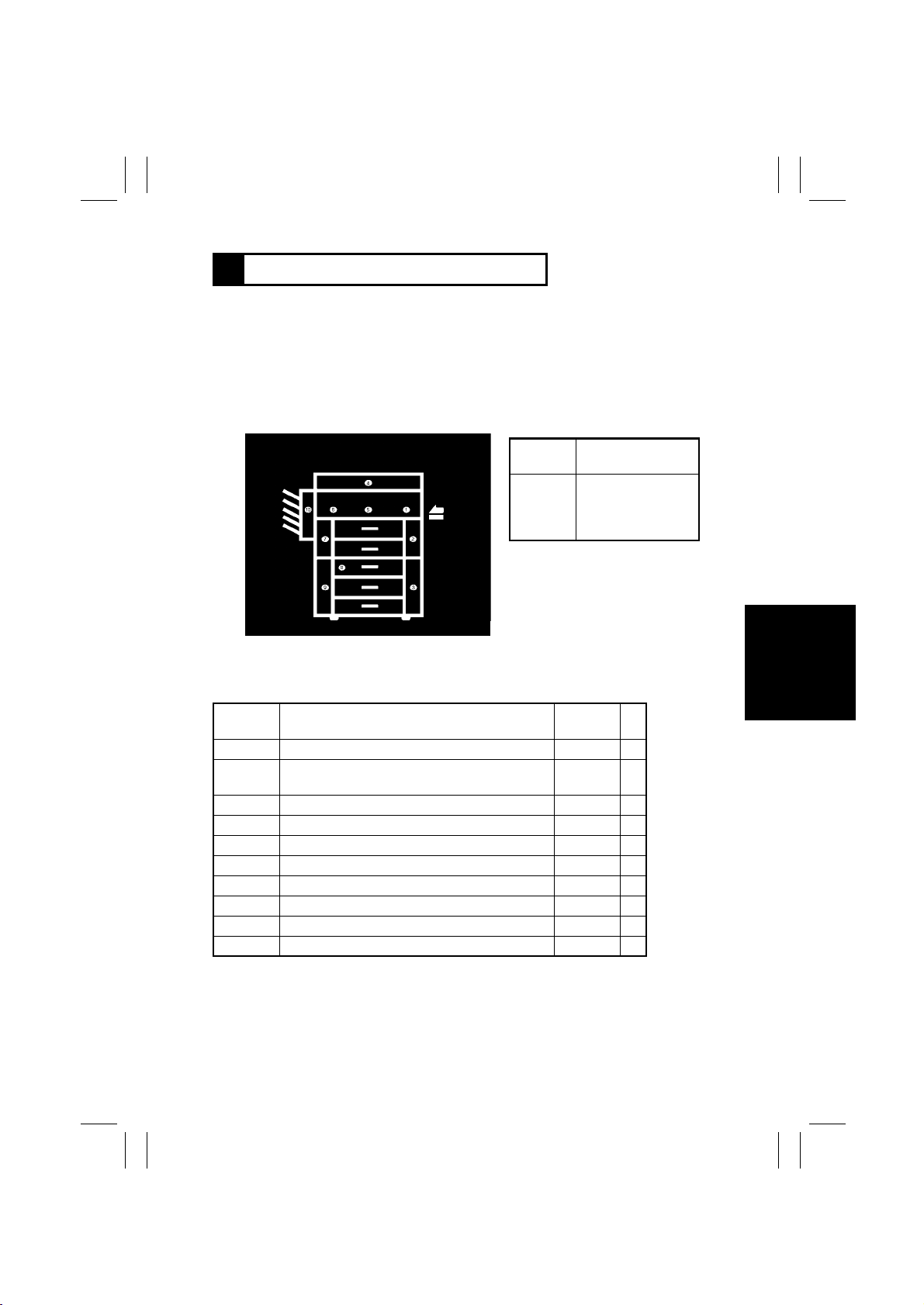
4 MALFUNCTIONS
4-1. Self-Diagnostic Function
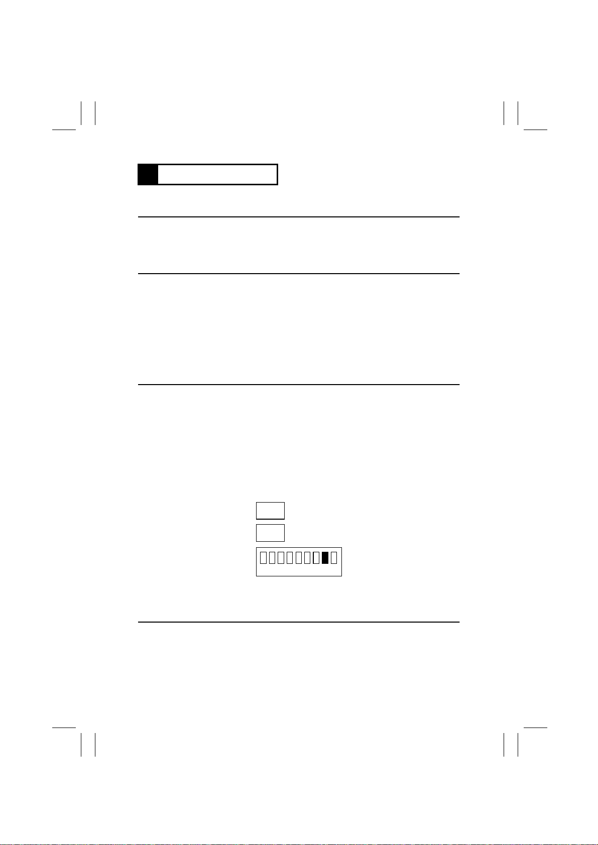
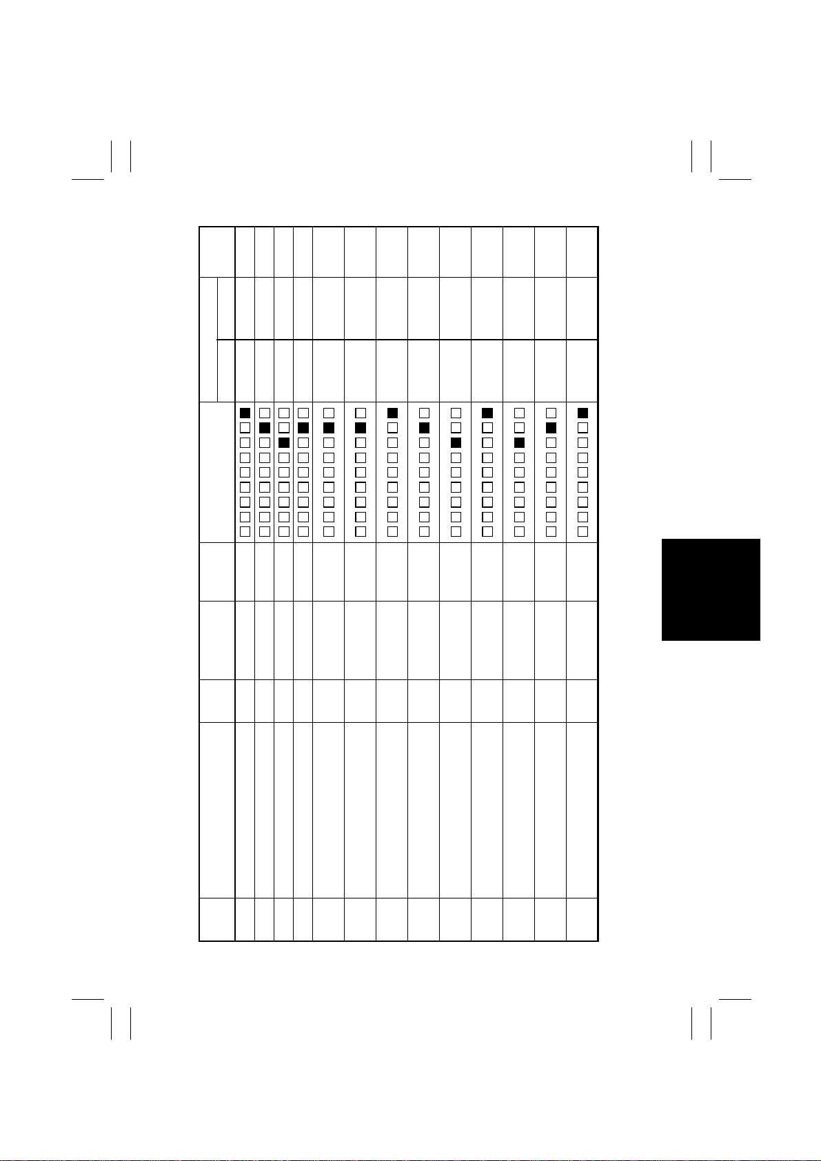
The copier CPU is capable of self-diagnosis of the copier conditions and, when detecting a
malfunction, it shows the corresponding malfunction code across the Zoom Ratio Indicator
and Multi-Co py Display. Each malfunction code indicates the particular part which has
developed a malfunction and the type of malfunction. A listing follo ws showing all malfunction codes and the description and possible causes of each malfunction.
Zoom Ratio Indicator Multi-Copy Display
C0
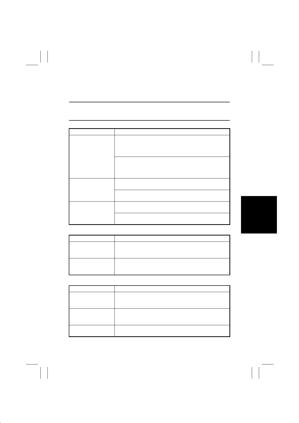
Malfunctions can be reset by the following procedure.
•
Malfunction Resetting Procedure
•
Open and clos e the Front Door. The Trouble Reset Switch must be pressed after the
Power is switched ON to reset the malfunc ti on of the Fusing a nd Exposure Lamp Sections.
•
Disconnect and connect t he option or open and close the option do or for malfunctions of
options.
×××
×××
××××××
Represents the detail of the malfunction.
Indicates the particular malfunctioning part of the
greater physical unit.
Indicates the malfunctioning physical unit.
Copier/Paper Feed C abinet (Option)
✽
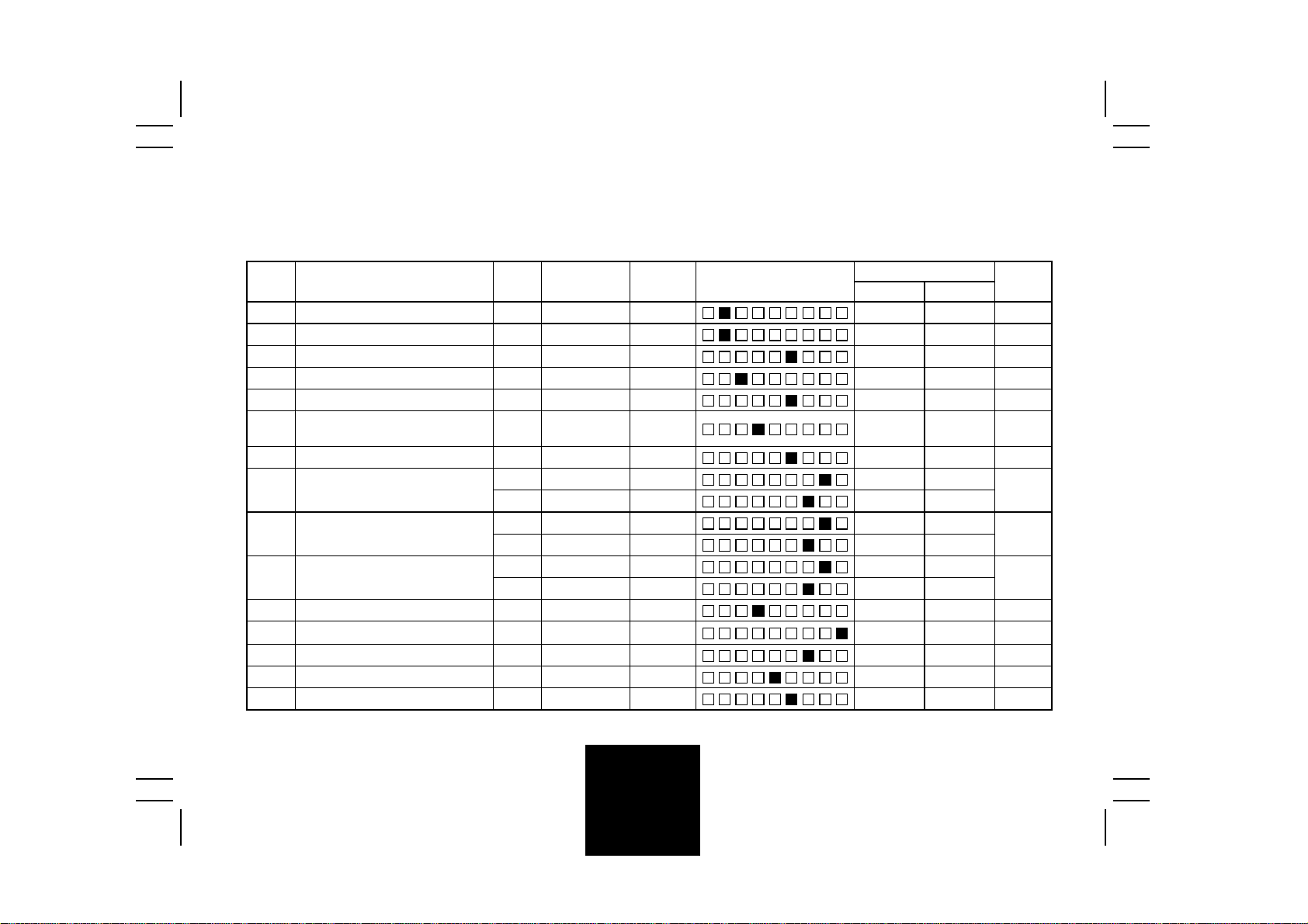
Code Description Detection Timing
C0000 Main Drive Motor's
failure to turn
C0001 Main Drive Motor turn-
ing at abnormal timing
C0010 PC Drive Motor's fa ilure
to turn
C0011 PC Drive Motor turning
at abnormal timing
C004C Cooling Fan Motor's
failure to turn
Drive
C0070 Toner Replenishing
Motor's failure to turn
C0071 Toner Replenishing
Motor turning at
abnormal timing
The lock signal remains HIGH for a continuous 1
second or more period while M2 is energized.
The lock signal remains LO W for a continuous 1
second or more period whil e M2 i s deenergized.
The lock signal remains HIGH for a continuous 1
second or more period while M1 is energized.
The lock signal remains LO W for a continuous 1
second or more period whil e M1 i s deenergized.
The lock signal remains HIGH for a continuous 3
second or more period while M9 is energized (it
turns at high speed).
Toner Hopper Home Pos i tion Sensor PC112
•
does not go from LOW to HIGH within 12 seconds after M8 has been energized.
PC112 does not go LOW within 12 seconds
•
after M8 has b een ene rgiz ed and PC1 12 g one
HIGH.
PC112 is HIGH 2 seconds afte r M8 has been de
energized.
T-33
Page 37

FrameMaker Ver.5.5(PC) EP1054/EP1085/EP2030 TROUBLESHOOTING
98.05.15
Copier/Paper Feed C abinet (Option)
✽
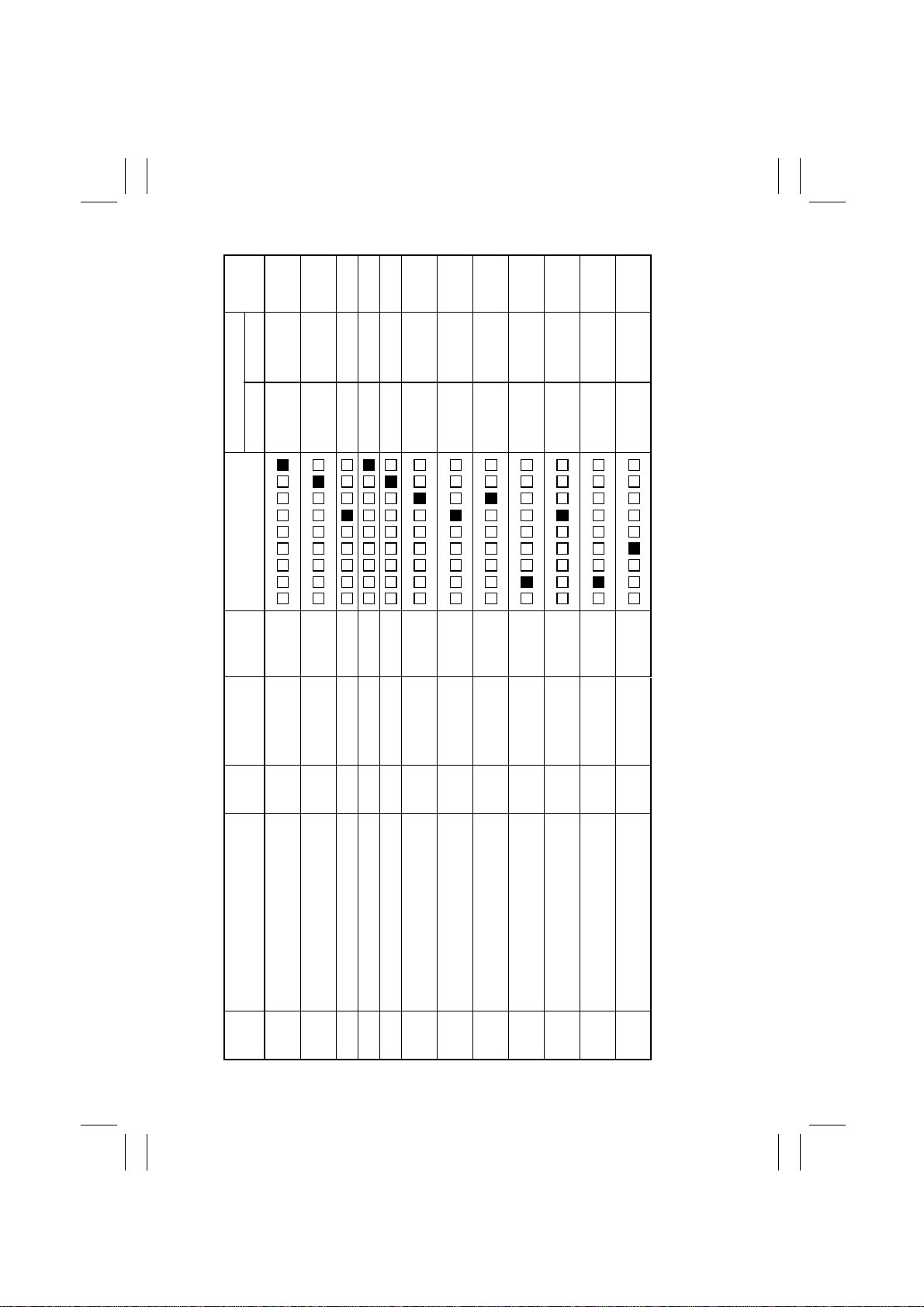
Code Description Detection Timing
C0400 Exposure Lamp's failure
to turn ON
C0410 Exposure Lamp turning
ON at abnormal timing
Exposure Lamp
C0500 Warm-up failure
C0510 Abnormally low fusing
Fusing Unit
C0520 Abnormally high fusing
C0600 Scanner Motor malfunc-
C0610 Lens Motor malfunction
Optical Section
C0620 Mirror Motor malfunction•The output from the Mirror Reference Position Sensor
C0F10 F aulty AE Sensor level
C0F30 ATDC Sensor malfunc-
Sensors
temperature
temperature
tion
tion
The output from AE Sensor Board PWB-H does not
become 4.3V or less for the period between when LA1
turns ON and the Scanner starts a scan motion and when
the Scanner reaches the Image Leading Edge position.
With LA1 OFF, the output from PWB-H remains 4.1V or
less for a continuous 2 second period at any timing while
the Scanner is at the home position or the Original Cover
is lowered.
If a given period of time has elapsed during warming-up,
the surface temperature of the Upper Fusing Roller does
not reach:
50°C within 20 seconds;
•
90°C within 20 seconds after it has reached 50°C; or
•
150°C within 20 seconds after it has reached 90°C.
•
The copier does not complete its warming-up cycle within
15 seconds after the above surface temperature has
reached 150°C.
The surface temperature of the Upper Fusing Roller
•
remains less than 135°C for a continuous 1 second or
more period after the copier has warmed up.
The surface temperature of the Upper Fusing Roller
•
remains less than 80°C for a continuous 1 second or
more period while in energy saving mode.
The surface temperature of the Upper Fusing Roller
remains 230°C or more after the copier has warmed up.
When the Scanner is at a position other than home,
•
Scanner Reference Position Sensor PC81 does not go
from HIGH to LOW after the lapse of 20 seconds after
the Power Switch has been turned ON.
When the Scanner is at the home position, PC81 does
•
not go from LOW to HIGH after the lapse of 5 seconds
after the Scanner has started a scan motion.
PC81 does not go from HIGH to LO W after the lapse of
•
20 seconds after the Scanner has started a scan
motion.
The output from Lens Reference Position Sensor PC90
does not go from HIGH to LOW, or vice versa, after the
lapse of 15 seconds after M6 has started turning.
PC86 does not go from HIGH to LO W after the lapse of
10 seconds after M7 has started turning.
The output from PC86 does not go from LOW to HIGH
•
after the lapse of 3 seconds after M7 has started turn-
ing.
The output from PWB-H does not fall within the 2V – 4V
range during the initial F5 mode.
The output from UN3 remains 0.4V or less, or 4.6V or
more, for a continuous 2 second period 2 seconds after
PC Drive Motor M2 has started turning.
T-34
Page 38

FrameMaker Ver.5.5(PC) EP1054/EP1085/EP2030 TROUBLESHOOTING
98.05.15
Malfunctions Detected by Copiers, Except in Europe
✽
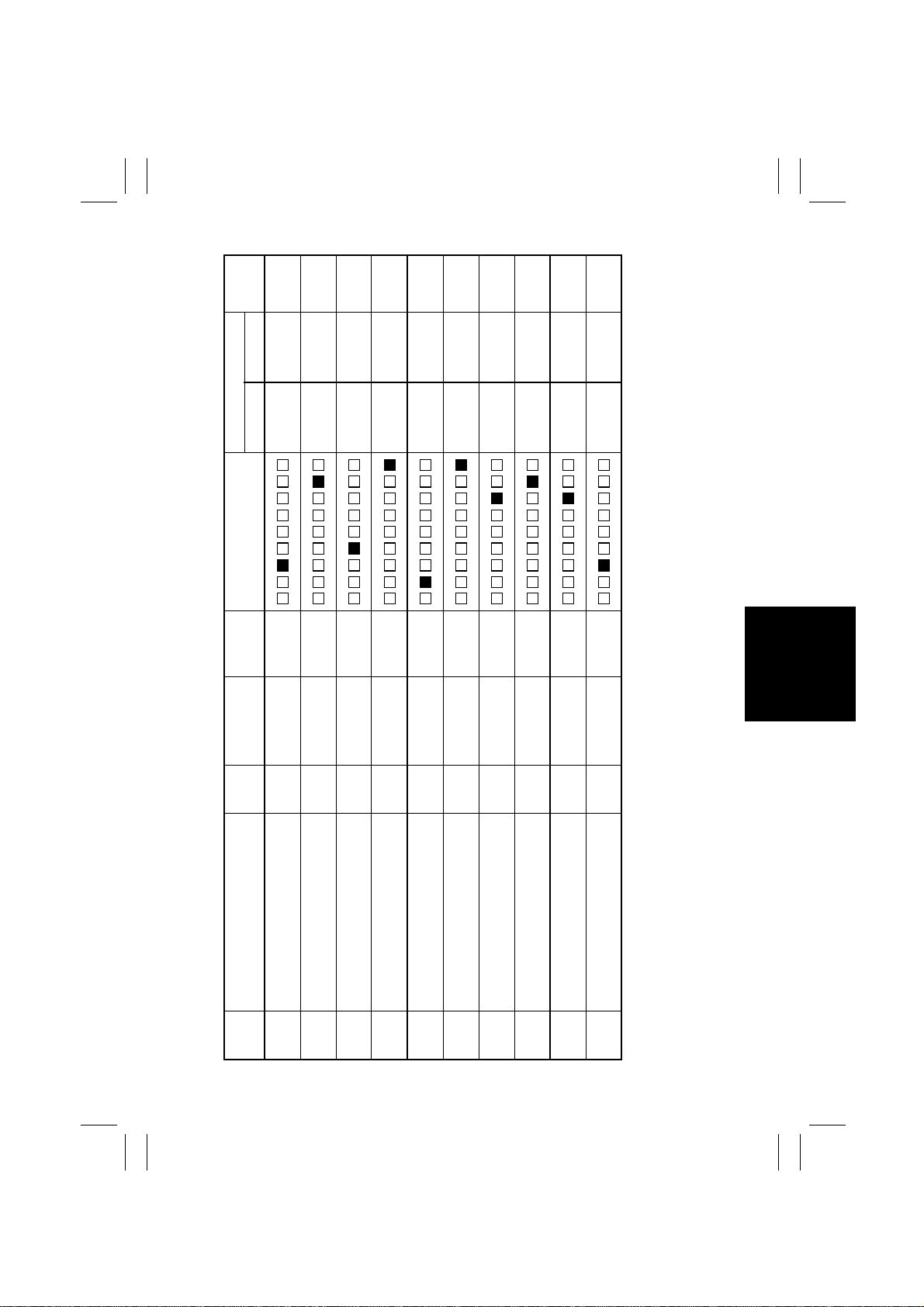
Code Description Detection Timing
C0F02 Original size detection
C0FE2 Original Size Detecting
C0FE4 Original Size Detecting
C0FE6 Original Size Detecting
C0FE8 Original Size Detecting
C0FEA Original Size Detecting
C0FEC Original Size Detecting
C0FEE Original Size Detecting
C0FF0 Original Size Detecting
C0FF2 Original Size Detecting
Original Size Detecting Board
C0FF4 Original Size Detecting
C0FF6 Original Size Detecting
C0FF8 Original Size Detecting
C0FFA Original Size Detecting
C0FFC Original Size Detecting
C0FFE Original Size Detecting
error (Defective CPU)
Sensor ➋ failure
Sensor ➌ failure
Sensors ➋ and ➌ failure
Sensor ➍ failure
Sensors ➋ and ➍ failure
Sensors ➌ and ➍ failure
Sensors➋, ➌ and ➍ failure
Sensor ➎ failure
Sensors ➋ and ➎ failure
Sensors ➌ and ➎ failure
Sensors ➋, ➌ and ➎ failure
Sensors ➍ and ➎ failure
Sensors ➋, ➍ and ➎ failure
Sensors ➌, ➍ and ➎ failure
Sensors ➋, ➌, ➍ and ➎
failure
Either UN2 is faulty or a commu ni cation error
•
occurs w ith PW B-A.
Under normal conditions :
•
The fixed-cycle pulse signal (Busy) remains
HIGH or LOW for 3 seconds or more.
When the Power Switch is ON:
•
The Busy signal r emai ns HIGH or LOW for 5
seconds or more.
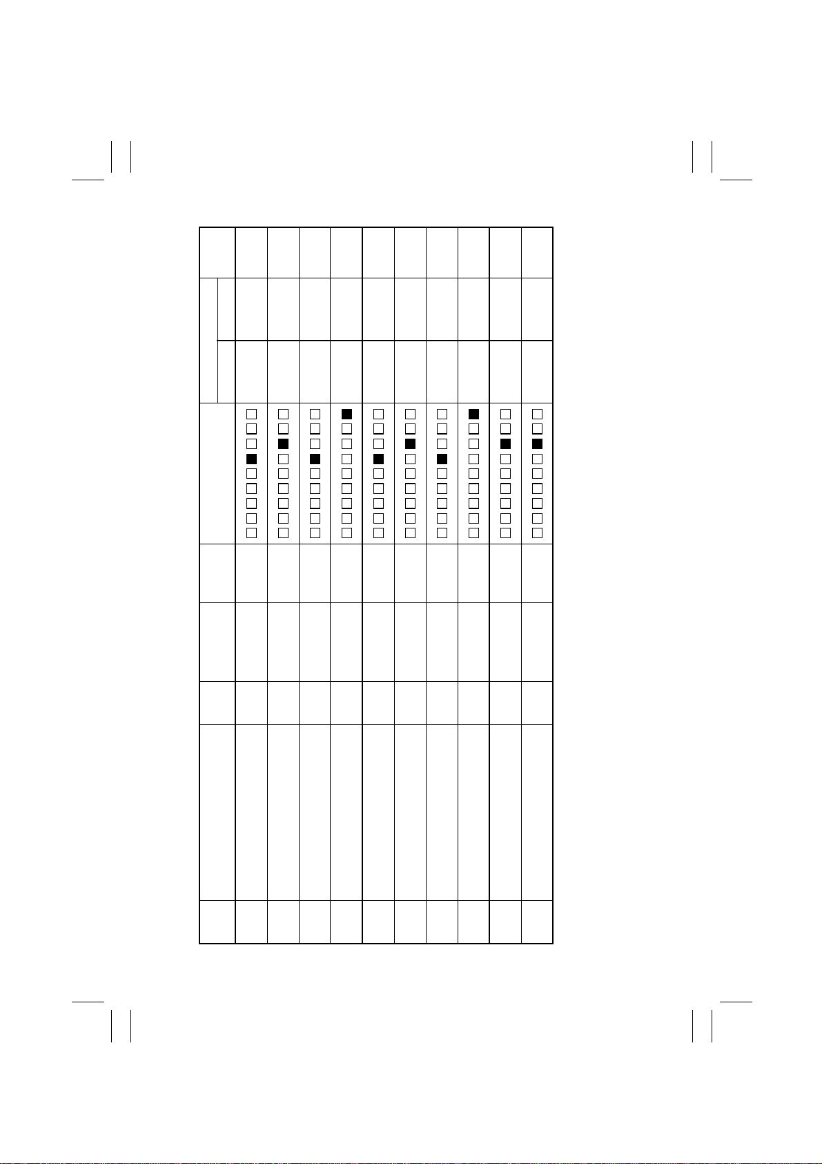
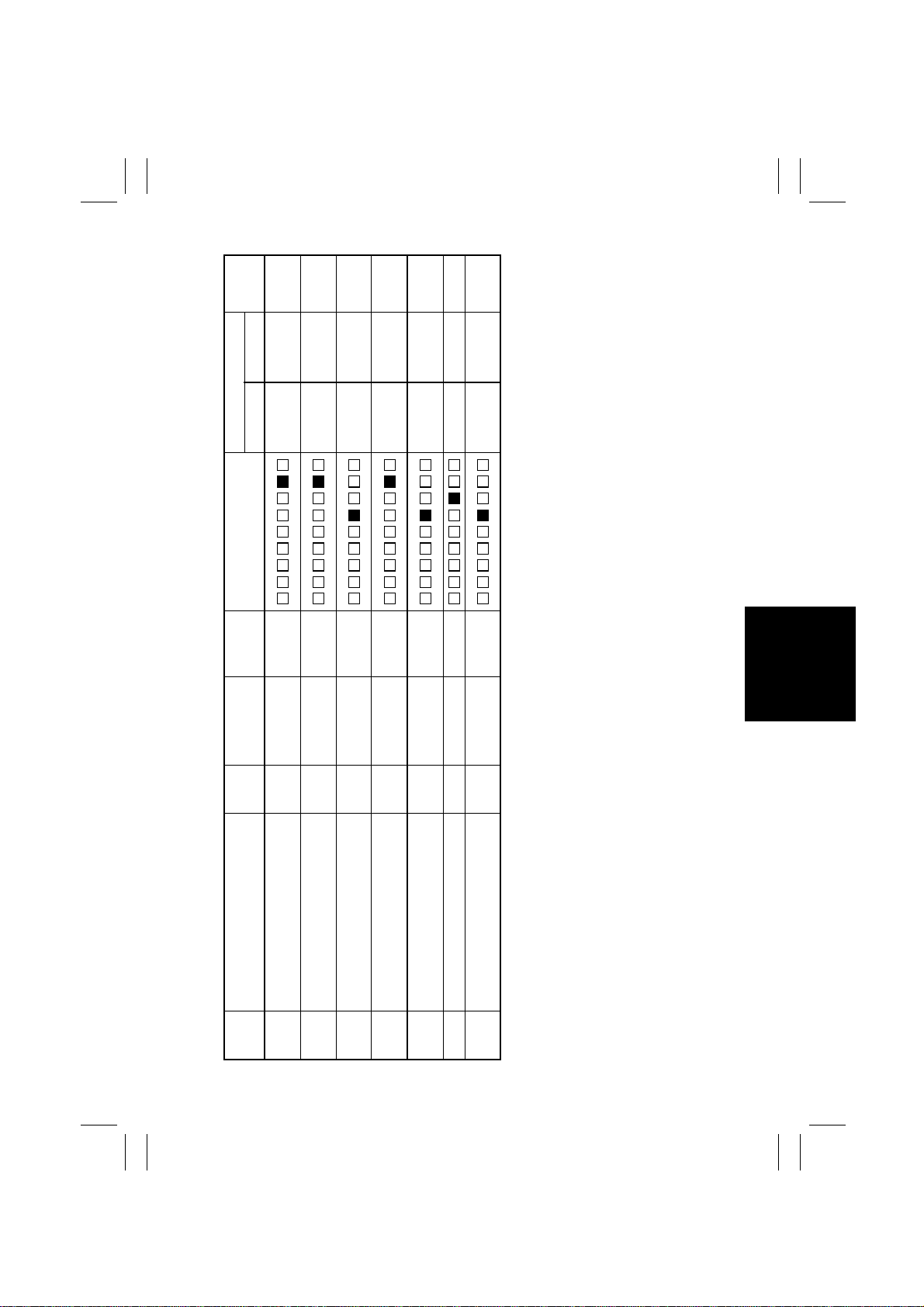
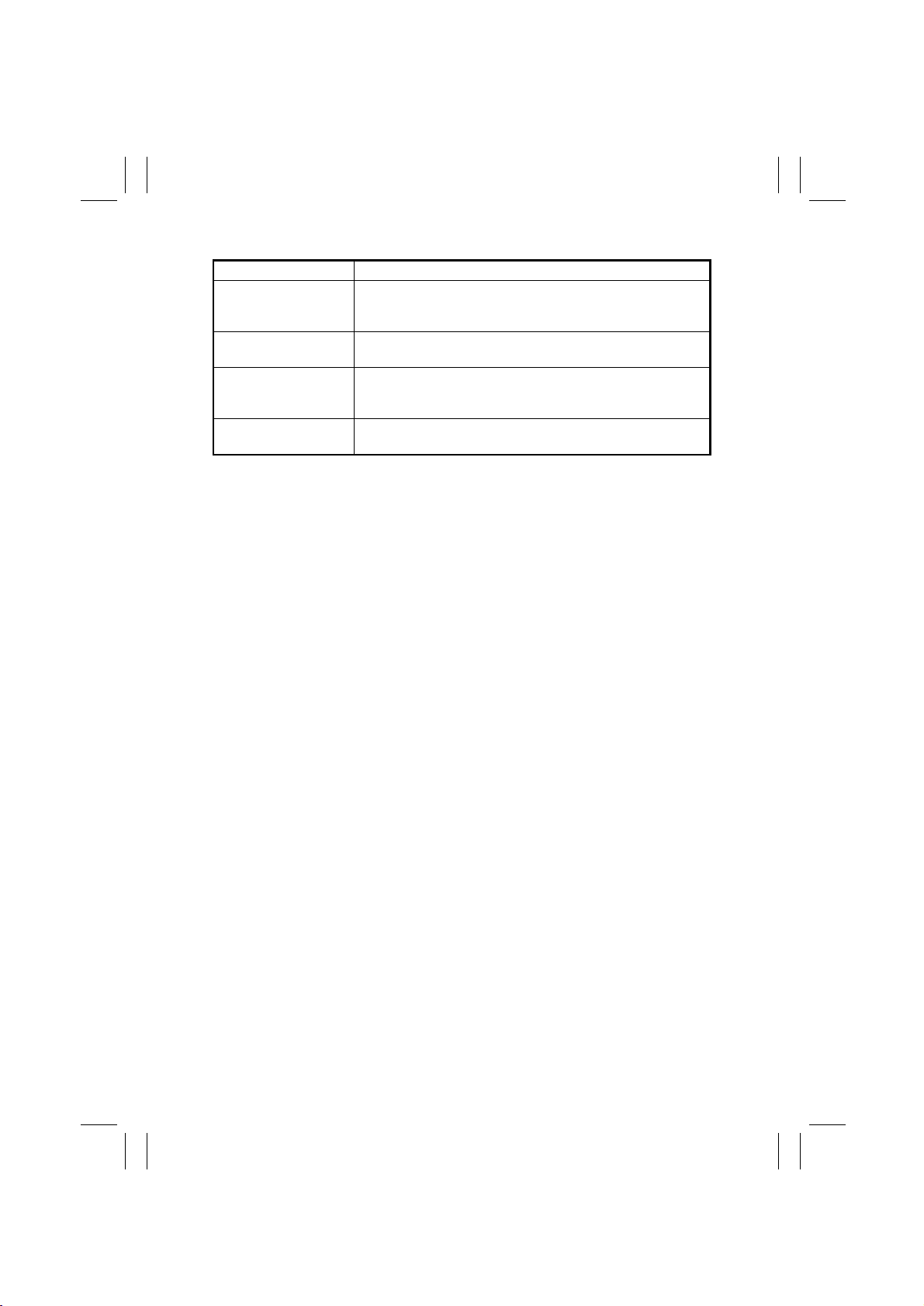
<Detection Timing>
After having read the output data from PC113 to
PC116, UN2 determines that there is a failure.
<Sensor Layout>
(Metric Areas)
: PC113, ➌: PC115 (option),
• ➋
: PC114, ➎: PC116 (option)
➍
PC115 and PC116 are standard for Mixed
✽
inch/metric areas.
A to E: Sensor locations
•
A
BCD E
A
B
➍
➎
(Inch Areas)
: PC113, ➌: PC115 (option),
• ➋
: PC114, ➎: PC116 (option)
➍
A
BCD E
A
B
➍
➎
➋
➋
➌
➌
T-35
Page 39

FrameMaker Ver.5.5(PC) EP1054/EP1085/EP2030 TROUBLESHOOTING
98.05.15
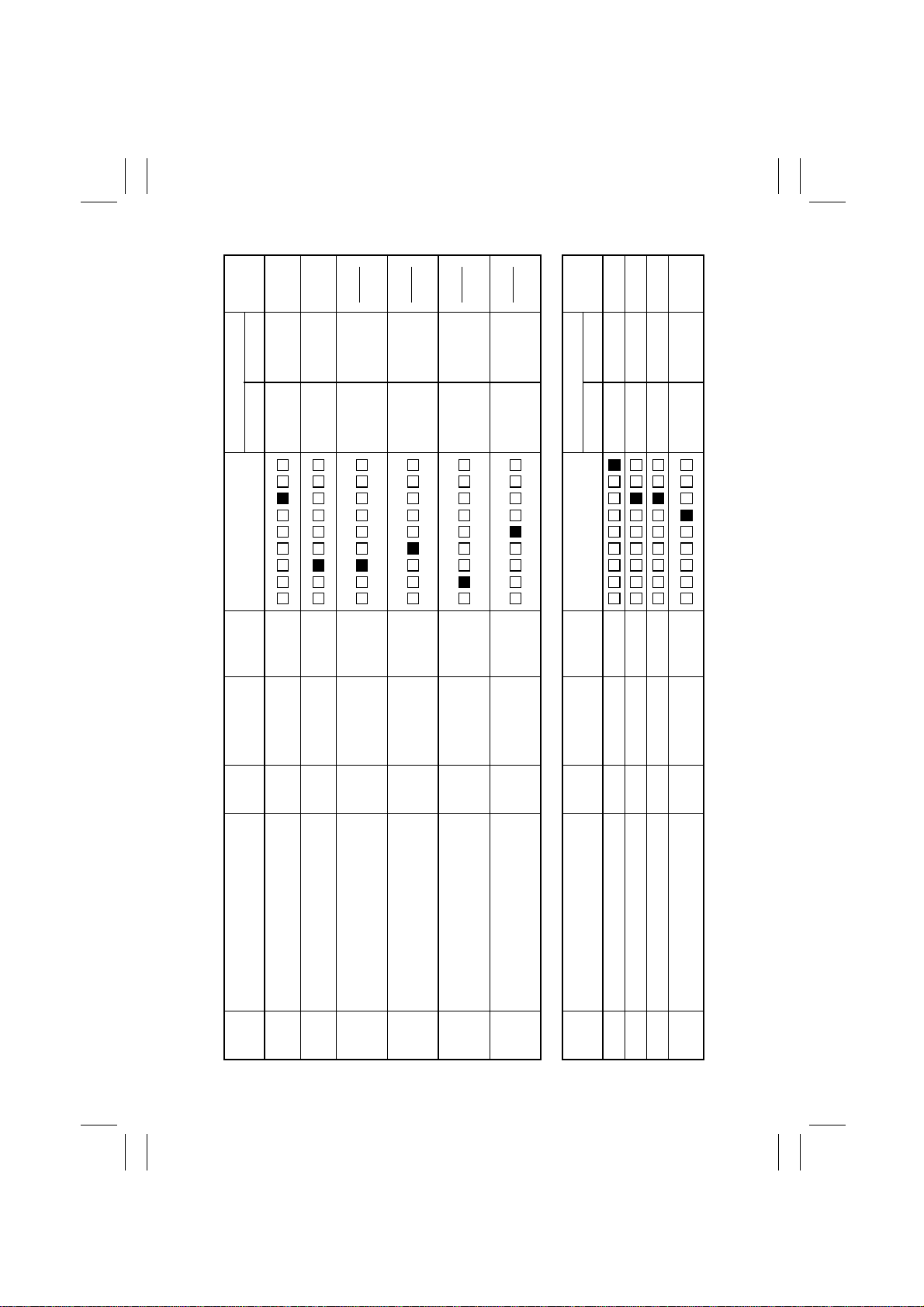
Code Description Detection Timing
C0900 3rd Drawer Paper Lift-
Up Sensor malfun ction
C0904 3rd Drawer Paper Lift-
C0950 4th Drawer Paper Lift-
PF-206
C0954 4th Drawer Paper Lift-
C0d00 Duplex Unit Fron t/Rea r
C0d20 Duplex Unit Trailing
C0d50 Duplex Unit Drive
AD-11/PF-6D
C0d51 Duplex Unit Drive Motor
Up Motor malfunction
Up Sensor malfun ction
Up Motor malfunction
Edge Guide Plates
home position detection
failure
Gate Unit home position
detection failure
Motor's failure to turn
turning at abnormal timing
See the PF-206 Service Man ual.
See the AD-11/PF-6D Service Manual.
T-36
Page 40

FrameMaker Ver.5.5(PC) EP1054/EP1085/EP2030 TROUBLESHOOTING
98.05.15
Code Description Detection Timing
C0990 Main Tray upward
motion failure
C0991 Main Tray downward
C0992 Main Tray downward
C0993 Main Tray upward
C0994 Main Tray Elev ator
C0996 3rd Drawer lo ck release
C0998 Shifter transfer failure
C0999 Shifter return failure
C099A Shifter return failure
PF-112
C099b Shifter transfer failure
C099c Shifter Motor's failure to
C0F79•3rd Drawer Paper
C099E Shift Gate position
C099F Shift Gate position
motion failure
motion failure
motion failure
Motor's failure to turn
failure
turn
Empty Sensor failure
Main Tray Paper
•
Empty Board failure
Shift Tray Paper
•
Empty Sensor
detecting failure
detecting failure
See the PF-112 Service Man ual.
T-37
Page 41

FrameMaker Ver.5.5(PC) EP1054/EP1085/EP2030 TROUBLESHOOTING
98.05.15
Malfunctions for Other Options
✽
Code Description Detection Timing
C0b10 Faulty P aper C lamp Uni t
movement
C0b11 Faulty P aper C lamp Uni t
movement
C0b30 Paper Aligning Motor
C0b31 Paper Aligning Motor
ST-104
C0b50 Improper stapling action
C0b51 Improper stapling action
C0b52 Improper stapling action
C0b60 Faulty Bin movement
C0b61 Faulty Bin movement
C0b62 Faulty Bin movement
C0b63 Faulty Bin movement
ST-104/S-106
C0b64 Faulty Bin movement
malfunction (Paper
Aligning Bar remaining
at home position)
malfunction (Paper
Aligning Ba r not at home
position)
(Stapler Arm remaining
at the home position)
(Stapler Arm not at
home position)
(stapling act i on occurring with no staples
driven into the paper)
(Defective Bin Moving
Motor)
(Defective drive)
(Defec tive Bin Positioning Sensor)
(Defective Bin Lower
Limit Position Sensor)
(M1 speed detection failure)
See the ST-104/S-106 Service Manual.
T-38
Page 42

FrameMaker Ver.5.5(PC) EP1054/EP1085/EP2030 TROUBLESHOOTING
98.05.15
4-2. Troubleshooting Procedures
(1) C0000: Main Drive Motor's fa il ure to turn
C0001: Main Drive Motor turning at abnormal timing
Symbol Name
M2
PWB-A
Main Drive Motor
Master Board
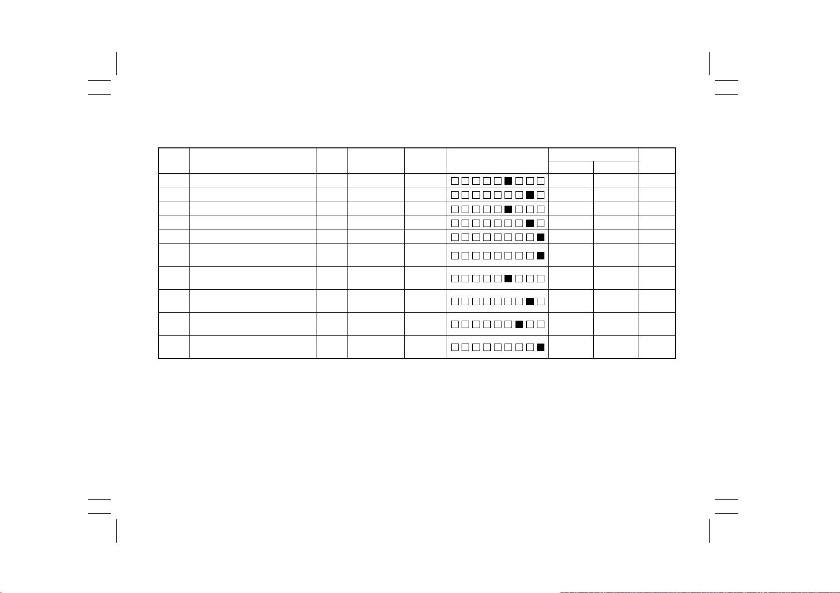
Step Check Item Result A ction
1 Is C0001 being shown? YES Begin with step 5.
Does M2 start to turn when the
2
Start Key i s pressed?
Does the voltage across PJ11A-14A on
PWB-A and GND change from DC5V to
3
DC0V when the Start Key is pressed?
Does the voltage across PJ11A-13A on
PWB-A and GND remain DC5V when
4
the Start Key is pressed?
Does the voltage across PJ11A-14A on
PWB-A and GND remain DC0V when
5
the Power Switch is turned ON?
Does the voltage across PJ11A-13A on
PWB-A and GND remain DC0V when
6
the Power Switch is turned ON?
Check rolls/rollers and gears for
NO
possible overload.
Replace PWB-A.
NO
YES Replace M2.
Replace PWB-A.
NO
Replace PWB-A.
YES
YES Replace M2.
Replace PWB-A.
NO
T-39
1174C25TAA
Page 43

FrameMaker Ver.5.5(PC) EP1054/EP1085/EP2030 TROUBLESHOOTING
98.05.15
(2) C0010: PC Drive Motor's failure to turn
C0011: PC Drive Motor turning at abnormal timing
Symbol Name
M1
PWB-A
PC Drive Motor
Master Board
Step Check Item Result A ction
1 Is C0011 being shown? YES Begin with step 5.
Does M1 start to turn when the Start
2
Key is pressed?
Does the voltage across PJ11A-12A on
PWB-A and GND change from DC24V
3
to DC0V when the Start Key is
pressed?
Does the voltage across PJ11A-11A on
4
PWB-A and GND remain DC5V when
the Start Key is pressed?
Does the voltage across PJ11A-12A on
5
PWB-A and GND remain DC0V when
the Power Switch is turned ON?
Does the voltage across PJ11A-11A on
PWB-A and GND remain DC0V when
6
the Power Switch is turned ON?
Check gears for possible overload.
NO
Replace PWB-A.
NO
YES Replace M1.
Replace PWB-A.
NO
Replace PWB-A.
YES
YES Replace M1.
Replace PWB-A.
NO
T-40
1174C26TAA
Page 44

FrameMaker Ver.5.5(PC) EP1054/EP1085/EP2030 TROUBLESHOOTING
98.05.15
(3) C004C: Cooling Fan Motor's failure to turn
Symbol Name
M9
PWB-A
Cooling Fan Motor
Master Board
C004C
Step Check Item Result A ction
Does the voltage across PJ20A-1
on PWB-A and GND change from
1
DC24V to DC12V when t he Power
is switched ON?
YES Replace M9.
Replace PWB-A.
NO
1174C27TAA
T-41
Page 45

FrameMaker Ver.5.5(PC) EP1054/EP1085/EP2030 TROUBLESHOOTING
98.05.15
(4) C0070: Toner Replenishing Motor's failure to turn
C0071: Toner Replenishing Motor turning at abnormal timing
Symbol Name
PC112
M8
PWB-A
Toner Hopper Home Position Sensor
Toner Replenishing Motor
Master Board
Step Check Item Result A ction
1 Is C0071 being shown? YES Begin with step 3.
Does the T oner Bottle turn when two
or three copies are made with the
2
Original Co ver raised?
Make two or three copies with the
Original Cover raised. Does the voltage
across PJ17A-2B on PWB-A and GND
3
change to DC0V when the Toner Bottle
is stopped and to DC5V when the Bottle
is turned during the copy cycle?
Make two or three co p ies with the O riginal Cover raised. Does the voltage
across PJ5A-6A on PWB-A and GND
4
change to DC0V when the Toner Bottle
is stopped and to DC24V when the Bottle is turned during the copy cycle?
YES Perform step 3.
Perform step 4.
NO
YES Replace PWB-A.
Check the Bottle Holder or PC112.
NO
YES Replace M8.
Replace PWB-A.
NO
T-42
1174C28TAA
Page 46

FrameMaker Ver.5.5(PC) EP1054/EP1085/EP2030 TROUBLESHOOTING
98.05.15
(5) C0400: Exposure Lamp's failure to turn ON
C0410: Exposure Lamp turning ON at abnormal timing
Symbol Name
LA1
TF2
PWB-A
PWB-H
PU1
Exposure Lamp
Exposure Lamp Thermal Fu se
Master Board
AE Sensor Boa r d
Exposure Lamp Regulator
T-43
1174C13TAC
Page 47

FrameMaker Ver.5.5(PC) EP1054/EP1085/EP2030 TROUBLESHOOTING
98.05.15
C0400
Step Check Item Result A ction
Does LA1 light up w hen the Start
1
Key is pressed? YES
Does the voltage across PJ14A-3
on PWB-A and GND become
2
DC4.3V or less when LA1 turns
ON?
Disconnect CN7 (2P). Is there con-
3
tinuity across CN7-1 and 2 on the
LA1 side?
Is the volt age across CN1-1 and 3
on PU1 AC1 00V?
4
C0410
Step Check Item Result A ction
Does LA1 turn ON when the P ower
Switch is turned ON or in the
1
standby state?
Does the voltage across PJ14A-3
on PWB-A and GND remain
2
DC4.1V or lower when the Power
Switch is turned ON or in the
standby state?
Check the photo receiver of the AE
Sensor for contamination.
Replace PWB-H o r PWB-A.
Replace PWB-A.
NO
Check LA1 and TF2 for continuity.
NO
YES Replace PU1.
Check Power Supply Unit PU2 and
NO
Power Supply Board PWB-C.
Check to see if the photo receiver of
the AE Sensor is receiving extrane-
NO
ous light.
Replace PWB-H o r PWB-A.
YES Replace PWB-A.
Replace PU1.
NO
T-44
Page 48

FrameMaker Ver.5.5(PC) EP1054/EP1085/EP2030 TROUBLESHOOTING
98.05.15
(6) C0500: Warm-up failure
C0510: Abnormally low fusing temperature
C0520: Abnormally high fusing temperature
Symbol Name
H1
TS1
TH1
PWB-A
SSR1
Fusing Heater La mp
Fusing Thermoswitch
Fusing Thermistor
Master Board
Fusing Heater Lamp SSR
T-45
1174C14TAA
Page 49

FrameMaker Ver.5.5(PC) EP1054/EP1085/EP2030 TROUBLESHOOTING
98.05.15
C0500, C051 0
After resetting a C0510 condition, C0500 will be shown if the same problem recurs. For
✽
this reason, t he same troubles hooting procedure is used for C0500 and C0510.
Step Check Item Result A ction
Does H1 light up when the Power
Switch is turned ON?
1
Disconnect CN14 (4P). Is the resis-
2
tance across CN 14-2 and 3 on the
TH1 side infinit y?
Does the volt age ac ross PJ 7A -2 on
PWB-A and GND change from
3
DC5V to DC0V when the Front
Door is closed wi th the Power
Switch ON?
Disconnect CN5 (2P). Is there con-
4
tinuity across CN5-1 and 2 on the
Fusing Unit side?
C0520
Step Check Item Result A ction
Does H1 remain lit u p e ven a fter the
1
copier has completed warming up?
Does the volt age ac ross PJ 7A -2 on
PWB-A and GND remain DC0V
2
even after the copier has completed
warming up?
Disconnect CN14 (4P). Is the circuit
3
across CN14-2 and 3 o n the Fus ing
Unit side short-circuited?
Check TH1 for install ation or clean
YES
it.
NO Begin with step 3.
YES Replace TH1.
Replace PWB-A.
NO
Replace PWB-A.
NO
YES Replace SSR1.
Check H1 and TF1 for continuity.
NO
YES Begin with step 2.
NO Begin with step 3.
YES Replace PWB-A.
Replace SSR1.
NO
YES Replace TH1.
Replace PWB-A.
NO
T-46
Page 50

FrameMaker Ver.5.5(PC) EP1054/EP1085/EP2030 TROUBLESHOOTING
98.05.15
(7) C0600: Scanner Motor malfunction
C0610: Lens Motor malfunction
C0620: Mirror Motor malfunction
Symbol Name
M5
M6
M7
PC81
PC86
PC90
PWB-A
PWB-F
PWB-E
Scanner Motor
Lens Motor
Mirror Motor
Scanner Reference Position Se nsor
Mirror Reference Position Sensor
Lens Reference Position Sensor
Main Control Board
23 cpm Copier Motor Drive Board
15/18 cpm Copie r Motor Drive Board
T-47
1174C35TCB
Page 51

FrameMaker Ver.5.5(PC) EP1054/EP1085/EP2030 TROUBLESHOOTING
98.05.15
C0600
Step Check Item Result A ction
Are all connectors on Motor Drive
1
Board plugged in securely?
Check Scann er Reference Position
Sensor PC81.
2
See p. T-2 (PWB-A (IC4A) APB0)
Is the Scanner drive fau l ty? YES Correct or r eplace the faulty part.
3
C0610
Step Check Item Result A ction
Does M6 start turning after the
1
Po wer Switch has been turned ON?
Does the voltage across PJ16A-1B
on PWB-A and GND change from
2
DC24V to DC0V after the Power
Switch has bee n turned ON?
Check Lens Reference Position
Sensor PC90.
3
See p. T-2 (PWB-A (IC4A) APB1)
C0620
Step Check Item Result A ction
Does M7 start turning when the mir-
1
ror is out of position and the Power
Switch is turned ON?
Does the voltage across PJ16A-2B
on PWB-A and GND change from
2
DC24V to DC0V when the Mirror
moves?
Check Mirror Reference Position
Sensor PC86.
3
See p. T-2 (PWB-A (IC4A) APB2)
Plug them in secure l y.
NO
Check the Scanner Drive Cable for
YES
tension and overload. Or, replace
PWB-A.
NO Check PC81.
NO Replace Motor Drive Board or M5.
Perform step 4.
YES
YES Replace Motor Drive Board or M6.
Replace PWB-A.
NO
Check the Lens Drive Cable for ten-
YES
sion and overload. Or, replace
PWB-A.
NO Check PC90.
Perform step 3.
YES
YES Replace Motor Drive Board or M7.
Replace PWB-A.
NO
Check for overload. Or, replace
YES
PWB-A.
NO Check PC86.
T-48
Page 52

FrameMaker Ver.5.5(PC) EP1054/EP1085/EP2030 TROUBLESHOOTING
98.05.15
(8) C0900: 3rd Drawer Paper Lift-Up Sensor malfunction
C0904: 3rd Drawer Paper Lift-Up Motor malfunction
C0950: 4th Drawer Paper Lift-Up Sensor malfunction
C0954: 4th Drawer Paper Lift-Up Motor malfunction
Symbol Name
PC19
PC23
PC27
PC28
M24
M25
PWB-A
3rd Drawer Paper Lift-Up Sensor
4th Drawer Paper Li ft-Up Sensor
3rd Drawer Paper Lift-Up Motor Pulse
Sensor
4th Drawer Paper Lift-Up Motor Pulse
Sensor
3rd Drawer Paper Lift-Up Motor
4th Drawer Paper Lift-Up Motor
PF-206 Master Board
T-49
1174C16TAA
Page 53

FrameMaker Ver.5.5(PC) EP1054/EP1085/EP2030 TROUBLESHOOTING
98.05.15
C0900, C095 0
Step Check Item Result A ction
1 Is C0950 being shown? YES Perform step 3.
Check 3rd Drawer Paper Lift-Up
Sensor PC19.
2
See p. T-2 (PF-206) PWB-A IC1A
PG3.
Check 4th Drawer Paper Lift-Up
Sensor PC23.
3
See p. T-2 (PF-206) PWB-A IC1A
PF3.
C0904, C095 4
Step Check Item Result A ction
1 Is C0954 being shown? YES Begin with step 5.
Slide out the 3rd D r aw e r an d sli de it
2
back into t he co pier. Does M24 turn
at this time?
Does the voltage across PJ10A-3
on PF-206 PWB-A an d GND
change from DC0V to DC24V, and
3
then back t o DC0V again, after the
3rd Drawer has been slid back into
the copier?
Check 3rd Drawer Paper Lift-Up
Motor Pulse Sensor PC27.
4
See p. T-2 (PF-206) PWB-A IC1A
PC1.
Slide out the 4t h Dr a w er and sli de it
5
back into t he co pier. Does M25 turn
at this time?
Does the voltage across PJ10A-1
on PF-206 PWB-A an d GND
change from DC0V to DC24V, and
6
then back t o DC0V again, after the
4th Drawer has been slid back into
the copier?
Check 4th Drawer Paper Lift-Up
Motor Pulse Sensor PC28.
7
See p. T-2 (PF-206) PWB-A IC1A
PD1.
YES Replace PF-206 PWB-A.
Check the Paper Pressure Releas-
NO
ing mechanism and PC19.
YES Replace PF-206 PWB-A.
Check the Paper Pressure Releas-
NO
ing mechanism and PC23.
Perform step 4.
YES
YES Replace M24.
Replace PF-206 PWB-A.
NO
Replace PF-2 06 PWB-A. Or, check
YES
the gears f or possible o verload.
Check the Pulse Disk and PC27.
NO
Perform step 7.
YES
YES Replace M25.
Replace PF-206 PWB-A.
NO
Replace PF-2 06 PWB-A. Or, check
YES
the gears f or possible o verload.
Check the Pulse Disk and PC28.
NO
T-50
Page 54

FrameMaker Ver.5.5(PC) EP1054/EP1085/EP2030 TROUBLESHOOTING
98.05.15
(9) C0990: Main Tray Upward Motion Failure
C0991: Main T ray Downward Motion Failure
C0992: Main T ray Downward Motion Failure
C0993: Main T ray Upward Motion Failure
C0994: Main Tray Elevator M26's Failure to Turn
Symbol Name
PC2
PC5
PC19
PC35
M26
PWB-H
PWB-A
Main Tray Lower Position Sensor
Elevator Motor Puls e Sensor
3rd Draw er Paper Lift-Up Sensor
Lower Position Se nsor
Elevator Motor
Cabinet Transport Board
PF-112 Master Board
T-51
1174C17TAA
Page 55

FrameMaker Ver.5.5(PC) EP1054/EP1085/EP2030 TROUBLESHOOTING
98.05.15
C0990, C099 1
Step Check Item Result A ction
Check 3rd Drawer Paper Lift-Up
Sensor PC19.
1
See p. T-2 (PF-112) PWB-A IC1A
PG3.
C0992, C099 3
Step Check Item Result A ction
Check Lower Position Sensor
PC35.
1
See p. T-2. (PF-112) PWB-A IC2A
PB3
Check Main Tray Lower Pos ition
2
Sensor PC2. See p. T-2.
(PF-11 2 ) PWB-A IC2A PC 1
C0994
Step Check Item Result A ction
Does M26 turn when the Paper
1
Descent key is pressed?
Does the voltage across PJ10A-1
(down) on PF-112 PWB-A and
GND , a nd acro s s PJ10A- 2 (up ) and
2
GND , cha nge from DC0V to DC24 V
when the Drawer is slid in or the
Paper Descent key is pressed?
Does the volt age ac ross PJ 9A -5 on
PF-112 PWB-A and GND cha nge in
3
the range bet w een DC0V and
DC5V while M26 is turning?
YES Replace PF-112 PWB-A.
Check the Paper Pressure Releas-
NO
ing mechanism and PC19.
YES Replace PF-112 PWB-A.
Check PC35.
NO
YES Replace PF-112 PWB-A.
Check PC2.
NO
Perform step 3.
YES
Replace M26 or che ck PWB-H and
YES
flat cable.
Replace PF-112 PWB-A.
NO
YES Replace PF-112 PWB-A.
Check the pulse disk, Gear, and
NO
Sensor.
T-52
Page 56

FrameMaker Ver.5.5(PC) EP1054/EP1085/EP2030 TROUBLESHOOTING
98.05.15
(10) C0998: Shifter Transfer Failure
C0999: Shifter Return Failure
C099A: Shifter Return Failure
C099b: Shifter Transfer Failure
C099c: Shifter Motor M27's Failure to Turn
Symbol Name
PC3
PC4
PC6
M27
PWB-H
PWB-A
Shifter Home Position Sensor
Shifter Return Position Sensor
Shift Motor Pulse Sensor
Paper Shif t Motor
Cabinet Transport Board
PF-112 Master Board
T-53
1174C30TAA
Page 57

FrameMaker Ver.5.5(PC) EP1054/EP1085/EP2030 TROUBLESHOOTING
98.05.15
C0998, C099 9
Step Check Item Result A ction
Check Shifter Return Position Sen-
1
sor PC4. See p. T-2
(PF-11 2 ) PWB-A IC2A PD 1.
C099A, C099 b
Step Check Item Result A ction
Check Shifter Home Pos i tion Sen-
1
sor PC3. See p. T-2
(PF-11 2 ) PWB-A IC2A PC 0
C099C
Step Check Item Result A ction
Does M27 turn when the Drawer is
1
slid in with a pape r st ack loaded in
the Shift Tray?
Does the voltage across PJ10A-4
(moving to right ) on PF -112 P WB-A
2
and GND change from D C 0V to
DC24V when doing step 1?
Does the voltage across PJ9A-12
on PF-112 PWB-A an d GND
3
change from DC0V to DC5V while
M27 is turning?
YES Replace PF-112 PWB-A.
Check PWB- H , flat cable and PC4.
NO
YES Replace PF-112 PWB-A.
Check PWB- H , flat cable and PC3.
NO
Perform step 3.
YES
Replace M27 or che ck PWB-H and
YES
flat cable.
Replace PF-112 PWB-A.
NO
YES Replace PF-112 PWB-A.
Check the pulse disk, Gear, and
NO
Sensor.
T-54
Page 58

FrameMaker Ver.5.5(PC) EP1054/EP1085/EP2030 TROUBLESHOOTING
98.05.15
(11) C099E: Shift Gate Positi on Detecting Failure
C099F: Shift Gate Position Detecting Failure
C0996: 3rd Drawer Lock Release Failure
C0F79: Paper Empty Sensor Failure
Symbol Name
PC1
PC7
PC20
PC34
SL41
PWB-E
PWB-H
PWB-A
Shift Tray Paper Empty Sensor
3rd Dra wer Set Sensor
3rd Drawer Paper Empty Sensor
Shift Gate Position Detecting Sensor
3rd Drawer Lock Solenoid
Main Tray Paper Empty Board
Cabinet Transport Board
PF-112 Master Board
T-55
1174C31TAA
Page 59

FrameMaker Ver.5.5(PC) EP1054/EP1085/EP2030 TROUBLESHOOTING
98.05.15
C099E, C099 F
Step Check Item Result A ction
Check Shift Gate Position Detecting
Sensor PC34.
1
See p. T-2
(PF-11 2 ) PWB-A IC1A PC 1.
C0996
Step Check Item Result A ction
Does the volt age ac ross PJ 6A -2 on
PF-112 PWB-A and GN D change
from DC0V to DC24V when the
1
Paper Des cent Key is pressed and
the Main Tray has completed downward motion?
Check 3rd Dr a we r Set Se nsor P C7.
See p. T-2 (PF-112) PWB-A IC1A
2
PG2
C0F79
Step Check Item Result A ction
Check 3rd Drawer Paper Empty
1
Sensor PC20. See p. T-2
(PF-11 2 ) PWB-A IC1A PC 0.
Check Main Tray Paper Empty
Board PWB-E. See p. T-2
2
(PF-11 2 ) PWB-A IC1A PF3.
Check Shift Tray Paper Empty Sen-
sor PC1.
3
See p. T-2
(PF-11 2 ) PWB-A IC1A PD 1
YES Replace PF-112 PWB-A.
Check PWB- H , flat cable and
NO
PC34.
YES Replace SL41.
Replace PF-112 PWB-A.
NO
YES Replace PF-112 PWB-A.
Check PWB- H , flat cable and
NO
PC25.
YES Replace PF-112 PWB-A.
Check PC20.
NO
YES Replace PF-112 PWB-A.
Check PWB- H , flat cable and PWB-
NO
E.
YES Replace PF-112 PWB-A.
Check PWB- H , flat cable and PC1.
NO
T-56
Page 60

FrameMaker Ver.5.5(PC) EP1054/EP1085/EP2030 TROUBLESHOOTING
98.05.15
(12) C0d00: Duplex Unit Front/Rear Edge Guide Plates home position
Symbol Name
PC8
PC9
M31
M32
M33
PWB-G
detection failure
C0d20: Duplex Unit Trailing Gate Unit home position detection failure
C0d50: Duplex Unit Drive Motor's failure to turn
C0d51: Duplex Unit Drive Motor turning at abnormal timing
Duple x Gate Home Position Sensor
Front/Rear Edge Guide Plate Home
Position Sensor
Duplex Unit Drive Motor
Gate Motor
Front/Rear Edge Guide Drive Motor
Duplex Unit Master Board
T-57
1151C11TAA
Page 61

FrameMaker Ver.5.5(PC) EP1054/EP1085/EP2030 TROUBLESHOOTING
98.05.15
C0d00, C0d2 0
Step Check Item Result A ction
1 Is C0d20 being shown? YES Perform step 4.
Does Front/Rear Edge Guide Drive
Motor M33 start turning when the
2
Power Switch is turned ON or the
Duplex Unit slid into pos ition?
Check F r ont/Re ar Edge Gu ide plate
Home positio n sensor PC9. See p.
3
T-2 (AD-11) PWB-G IC1G PC3.
Does Gate Motor M32 start turning
when the Power Switch is turned
4
ON or the Duplex Unit slid into posi tion?
Check Duplex Gate Home Position
Sensor PC8. See p. T-2 (AD-11)
5
PWB-G IC1G PE0.
C0d50, C0d5 1
Step Check Item Result A ction
1 Is C0d51 being shown? YES Begin with step 5.
Does Duplex Unit Drive Motor M31
2
start turning when the Start Key is
pressed.
Does the v ol ta ge ac ross PJ6G -2 on
PWB-G and GND ch ange from
3
DC5V to DC0V when the Start Key
is pressed?
Does the v ol ta ge ac ross PJ6G -1 on
PWB-G and GND remain DC5V
4
when th e St art Key is press e d?
Does the v ol ta ge ac ross PJ6G -2 on
PWB-G and GND remain DC0V
5
when the Power Switch is turned
ON?
Does the v ol ta ge ac ross PJ6G -1 on
PWB-G and GND remain DC0V
6
when the Power Switch is turned
ON?
Check for possible overload.
Replace PWB- G, PWB-A of PF-
NO
206/PF-112/PF-6D, or M33.
Replace PWB-G or PWB-A of PF-
YES
206/PF-112/ PF - 6D.
NO Check PC9.
Check for possible overload.
Replace PWB- G, PWB-A of PF-
NO
206/PF-112/PF-6D, or M32.
Replace PWB-G or PWB-A of PF-
YES
206/PF-112/ PF - 6D.
NO Check PC8.
Check t he roller, rolls, and gears for
NO
possible overload.
Replace PWB-G or PWB-A of PF206/PF-112/ PF - 6D.
NO
YES Replace M31.
Replace PWB-G or PWB-A of PF-
NO
206/PF-112/ PF - 6D.
Replace PWB-G or PWB-A of PF-
206/PF-112/ PF - 6D.
YES
YES Replace M31.
Replace PWB-G or PWB-A of PF-
NO
206/PF-112/ PF - 6D.
T-58
Page 62

FrameMaker Ver.5.5(PC) EP1054/EP1085/EP2030 TROUBLESHOOTING
98.05.15
(13) C0F10: Faulty AE Sensor level
C0F30: A TDC Sensor malfunction
Symbol Name
PWB-A
PWB-H
UN3
Master Board
AE Sensor Boa r d
ATDC Sensor
C0F10
Step Check Item Result A ction
Is the voltage across PJ9A-3 on PWB-A
and GND in the range between DC2V
1
and DC4V when the Start Key is
pressed in the F3 operation?
C0F30
Step Check Item Result A ction
Is the volt age across PJ10A-3 on
1
PWB-A and GND DC0V after the
Po wer Switch has been turned ON?
Is the volt age across PJ10A-3 on
PWB-A and GND in the range
2
between DC0.5V and DC4.5V after
the Start Ke y has been pressed?
YES Replace PWB-A.
Check the photo receiver of the AE
NO
Sensor for conta mination or replac e
PWB-H.
Check the ATDC Sensor and the
YES
connection between the Imaging
Unit and copier.
YES Replace PWB-A.
Replace the ATDC Sensor.
NO
T-59
1174C20TAA
Page 63

FrameMaker Ver.5.5(PC) EP1054/EP1085/EP2030 TROUBLESHOOTING
98.05.15
(14)C0F02: Original size detection error (Defective CPU)
C0FE2 to C0FFE: Original Size Detecting Sensor failure
Symbol Name
PC113
PC114
PC115
PC116
UN2
PWB-A
Original Size Detecting Sensor FD2
Original Size Detecting Sensor CD1
Original Size Detecting Sensor FD3
Original Size Detecting Sensor CD2
Original Size Detecting Board
Master Board
C0F02
Step Check Item Result A ction
Is the jumper connector fitted prop-
1
erly across J1 and J2 on UN2?
Is PJ21 (CN2) plugged securely
2
into UN2 and PJ24A into PWB-A?
Does the LED of I/O port check
3
PWB-A (IC5A) PA3 blink after the
Po wer Switch has been turned ON?
C0FE2 to C0FFE
Step Check Item Result A ction
Is the jumper connector fitted prop-
1
erly across J1 and J2 on UN2?
Is each Original Size Detecting
2
Sensor installed at the correct position?
Is the malfuncti on code red is played
after the corres ponding Original
3
Size Detecting Sensor has been
changed?
NO
NO
YES•Change PWB-A.
NO
NO
NO
YES
Change the position of the
•
jumper connector.
Plug th em in s ecurely.
•
Change UN2.
•
Change the position of the
•
jumper connector.
Reinstall.
•
Change UN2 or PWB-A.
•
T-60
1174C21TAA
Page 64

FrameMaker Ver.5.5(PC) EP1054/EP1085/EP2030 TROUBLESHOOTING
98.05.15
(15) Power is not Turned ON
Symbol Name
PWB-A
PWB-C
PU1
PU2
Master Board
Po wer Supply Board
Exposure Lamp Regulator
Power Supply Unit
Power Switch
S1
Front Door Interlock Switch
S2
T-61
1174C33TAB
Page 65

FrameMaker Ver.5.5(PC) EP1054/EP1085/EP2030 TROUBLESHOOTING
98.05.15
Symptom
Power is not
supplied to the
copier at all.
Only the control
panel Indicators
light up.
If the problem persists even after the above procedures, t he harness is probabl y short-
✽
circuited.
Check the harnesses.
Step
1
2
3
4
5
Check Item
Is the source voltage being
supplied to the circuit
across PJ1-1 and 2 of
PU2?
Is the voltage acros s PJ2-2
of PU2 and GND, and
across PJ2- 3 on PU2 and
GND, DC24V?
Is the voltage acros s PJ2-1
of PU2 and GND DC 24V?
Is the voltage across PJ2C6 on PWB-C and GN D, and
across PJ2C-8 on PWB-C
and GND, DC24V?
Only the cont rol panel Indicators light up? YES
Result
Check Fuse or line voltage.
NO
Check Fuse of PU2 or
replace PU2.
NO
Check Fuse of PU2 or
NO
replace PU2.
Check Fuse of PWB-C or
replace PWB-C.
NO
Replace PWB-A.
Action
T-62
Page 66

FrameMaker Ver.5.5(PC) EP1054/EP1085/EP2030 TROUBLESHOOTING
98.05.15
(16)E1, E2
Symbol Name
UN3
PWB-A
F4
ATDC Sensor
I/U Fuse
Master Board
Code Step Check Item Result Action
E1
E2 3
Is the seal peeled off the open-
1
ing or starter been ful ly
charged?
Is the voltage across PJ10A-3
on PWB-A and GN D in the
2
range between DC0.5V and
DC4.5V afte r the St a rt Key has
been turned ON?
Is the voltage across PJ10A-6
on PWB-A and GN D 0V?
Peel off the seal an d turn the
NO
Power Switch OFF, then ON.
YES Replace PWB-A.
Replace the ATDC Sensor.
NO
YES Replace PWB-A.
NO Replace F4 or PWB-A.
T-63
1174C23TAB
Page 67

FrameMaker Ver.5.5(PC) EP1054/EP1085/EP2030 TROUBLESHOOTING
98.05.15
5 IMAGE FAILURES
5-1. Image Failure Troubleshooting
Image failures have many possible causes. For troubleshooting, it is necessary to determine whether a failure is attributable to a basic cause or any other cause.
In this chapter, troubleshooting is divided into “i nitial checks” and “troubleshooting procedures classified by image failure”. If an image f ailure has occurred, first make the initial
checks, then proceed to the corresponding image failure troubleshooting procedure.
5-2. Initial Checks
1. Place of installation
Is the source voltage normal? Does the voltage vary greatly?
•
Is the copier installed in a hot, hu mid place or in a place where temperatures vary
•
sharply?
Is the copier installed in a dusty place?
•
Is the copier subjected to direct sunlight?
•
Is the copier level?
•
2. Copy pap er
Is the recommended paper used?
•
Load recommended paper and make copies to s ee i f the problem persists.
➨
Is the paper damp?
•
Load new paper and make copies to see if the probl em persists.
➨
3. Original
Does the original used have a reddish background or is it written i n l i ght pencil?
•
Use the Test Chart to check the image.
➨
Is the original transparent or ar e transparenc i es being used?
•
Cover wit h white paper and make a copy.
➨
Are the Original Glass and ADF Transport Belt dirty or scratched?
•
If dirty, clean with alcohol. If s cratched, replace.
➨
4. PM pa rts (su pp l i es)
Have the PM parts (supplies) , such as the PC Drum, Cle aning Blade, and corona wires,
•
reached the end of their cleaning/replacement cy cles?
5. Adjustment items (registration, focus, AE level, etc.)
Among the adjustment items given in DIS/REASSEMBLY, ADJUSTMENT, is there any
•
adjustment that may remedy the image fail ure?
T-64
Page 68

FrameMaker Ver.5.5(PC) EP1054/EP1085/EP2030 TROUBLESHOOTING
98.05.15
5-3. Troubleshooting Procedures Classified by Image Failu res
<Image Failure Samples>
1. Blank copy 2. Black copy 3. Low image density
4. Foggy background 5. Black s treaks or bands 6. Black spots
7. Blank streaks or bands 8. Void areas 9. Smear on back
1149T012AA
T-65
Page 69

FrameMaker Ver.5.5(PC) EP1054/EP1085/EP2030 TROUBLESHOOTING
98.05.15
(1) Blank copy
Cause
Charging failure
Developing Unit
out of position
Image transfer
failure
Pape r gui de
shorting 10
Step
Check Item
Is the PC Drum Charge
1
Corona installed correctly?
Are the PC Drum Charge
2
Corona wire an d grid mesh
normal?
Is the wiring between High
V o ltage U nit HV1 and co rona
3
wire normal?
Is the PC Unit inserted all
4
the way into position?
Are the Ds Rolls in contact
5
with the PC Drum?
Is the Developing Unit con-
6
nector plugged in?
Is the drive transmission to
7
the De veloping Uni t no rmal ?
Is the Image Transfer
8
Corona wire normal?
Is the wiring b etween High
9
Voltage Unit HV1 and
corona wire normal?
Is the paper guide shorted
to the frame? YES
Result
Install correctly.
NO
Check and repl ace if n eces -
NO
sary.
YES Replace HV1.
Correct the wiring.
NO
Fully tighten the knob.
NO
Reinstall the Developing
NO
Unit.
Plug it in.
NO
Check and repl ace parts if
NO
necessary.
Check and repl ace if n eces -
NO
sary.
YES Replace HV1.
Correct wiring.
NO
Connect the paper guide
through the resistor to the
frame.
Action
(2) Bla ck copy
Cause
PC Drum grounding failure
Dev eloping bias
failure
Light path failure
Exposu r e La m p 's
failure to turn ON
Step
1
2
3
4
5
6
Check Item
Is the PC Drum properly
grounded?
Is the developing bias contact norma l?
Is the developing bias harness normal?
Has condensation formed
on the mirrors, lens, or PC
Drum?
Are the mirrors installed
properly?
Does the Exposure La m p
light up?
T-66
Result
Clean or replace the PC
NO
Drum Ground Plate.
Clean or replace the devel-
NO
oping bias contact.
YES
Replace the High Voltage Unit.
NO Replace th e ha rness.
Clean the mirrors and
YES
lenses, and run the Drum
Dehum operation.
Reinstall the mirrors.
NO
Take the action for malfunc-
NO
tion code C0400.
Action
Page 70

FrameMaker Ver.5.5(PC) EP1054/EP1085/EP2030 TROUBLESHOOTING
98.05.15
(3) Low Image Density
Cause
PC Drum life
PC Drum grounding failure
Drum charge
failure 4
Optical failure
Image transfer
failure
Dev eloping f ailure 9 Is Db adjusted properly? NO Make Db adjustment.
Step
1
2
3
5
6
7
8
10
11
Check Item
Does the PC Drum have
enough service life?
Do the fan motors turn
properly? (Oz one dete rioration, temperature rise)
Is the PC Drum properly
grounded?
Are the PC Drum Charge
Corona wire an d grid mesh
normal?
Is the wiring b etween High
Voltage Unit HV1 and
corona wire normal?
Are the mirrors and lenses
dirty or covered with condensation?
Is the Image Transfer
Corona dirty?
Is the copy paper damp?
Are the Ds Rolls in contact
with the PC Drum?
Is the developing bias
contact normal?
Result
Replace the PC Dru m .
NO
Troubleshoot the fan
NO
motors.
Clean or replace the PC
NO
Drum Ground Plate.
Check and repl ace if n eces -
NO
sary.
YES Replace HV1.
Correct the wiring.
NO
Clean the mirrors and
YES
lenses.
Clean the Image Transfer
YES
Corona or replace the wire.
Replace copy paper and
instruct the user in how to
store paper an d t o k e ep t he
YES
copier plugged in during th e
night.
Reinstall the Developing
NO
Unit.
Clean or replace the devel-
NO
oping bias contact.
Action
T-67
Page 71

FrameMaker Ver.5.5(PC) EP1054/EP1085/EP2030 TROUBLESHOOTING
98.05.15
(4) Foggy background
Cause
Cleaning failure
Optical failure 2 Is the mirror or lens dirty? YES Clean the mirror or lens.
PC Drum failure
Devel opin g failure
Main Erase Lamp
failure
Step
1
3
4
5
6
7
8
Check Item
Is the Cleaning Blade dirty
with foreign matter, paper
dust, etc. or is it scratched?
Is the PC Drum dirty with
forei gn matter, etc.? YES
Is the PC Drum properly
grounded?
Is the Sleeve Roller abnormally dirty?
Is the developing bias contact norma l?
Does the Main Erase Lamp
light up properly?
Is the Main Erase Lamp dirty?
Result
YES
NO
YES
NO
NO
YES
Action
Change the Cleaning
Blade.
Clean or replace the PC
Drum. Replace the Cle aning Blade if necessary.
Clean or replace the PC
Drum Ground Plate.
Clean the Sleeve Roller.
Check the Developer Scattering Prevention Se al to
see if it is deformed or dirty.
Clean or replace the developing bias contact.
Replace the Main Erase
Lamp.
Clean the Main Erase Lamp.
T-68
Page 72

FrameMaker Ver.5.5(PC) EP1054/EP1085/EP2030 TROUBLESHOOTING
98.05.15
(5) Black Streaks or Bands
Cause
Uneven charging
Cleaning failure
PC Drum failure
PC Drum Paper
Separator Fingers 5
Fusing failure
Optical failure
(6) Bla ck Spots
Cause
PC Drum failure
Fusing failure
Devel opin g failure
Dirty PC Drum
Pape r Separator
Fingers
Step
Step
Check Item
Are the PC Drum Charge
Corona wire an d grid mesh
1
dirty?
Is the Cleaning Blade dirty
2
with foreign matter, paper
dust, etc., or is it scratched?
Does the Cleaning Blade
3
make a correct lateral motion?
Is the PC Drum surface
4
dirty or scratched? YES
Are the PC Drum Paper Separator Fingers dirty , deformed or
faulty in operation?
Is the Upper Fusing Roller
6
dirty or scratched?
Are the Upper Paper Separa-
7
tor Fingers dirty or deformed?
Is the mirror or lens dirty
8
with foreign matter?
Check Item
Is the PC Drum surface
1
scratched or dirty with foreign matter?
Is the Upper Fusing Roller
2
dirty or scratched? YES
Is the amount of toner on
3
the Sleeve Roller proper?
Is the toner-to-carrier ratio
4
relatively high?
5 Is the Db value normal? NO Make Db adjustment.
Is the Developer Scattering
6
Prevention Se al de formed
or dirty?
Are the PC Drum Paper
7
Separato r Fingers dirty or
deformed?
Result
Clean or replace the PC
Drum Charge Corona.
YES
Check the operation of the
toner charging mechanism.
Replace the Clea n i ng
YES
Blade.
Check the operation of the
NO
Cleaning Blade.
Replace th e PC D r u m . If
necessary, replace the
Cleaning Blade.
Clean or replace the PC
YES
Drum Paper Separator Fingers.
Clean or replace the Upper
YES
Fusing Roller.
Clean or replace the Upper
YES
Paper Separator Fingers.
Clean the mirror or lens.
YES
Result
Clean or replace the PC
YES
Drum. If necessary, replace
the Cleaning Blade.
Check the Fusing Thermistor s . Cl e a n or replace
the Upper Fusing Roller.
To step 7.
YES
Change the toner-to-car-
YES
rier ratio.
Clean or replace the Devel-
YES
oper Scattering Prevention
Seal.
Clean or replace the PC
YES
Drum Paper Separator Fingers.
Action
Action
T-69
Page 73

FrameMaker Ver.5.5(PC) EP1054/EP1085/EP2030 TROUBLESHOOTING
98.05.15
(7) Blank Streaks or Bands
Cause
Plugged Db
Drum charge failure 2
Image transfer failure
Defective PC
Drum Paper Separator Fingers
Image Eras e
Lamp lit at abnormal timing
Fusing failure
Step
Check Item
Is the Db plugg ed w ith for-
1
eign matter, caked toner,
etc.?
Are the PC Drum Charge
Corona wire an d grid mesh
dirty?
Is the Drum Charge Corona
3
Wire Cleaner at the home
position?
Is the Image Transfer
4
Corona wire dirty?
Is the Corona Wire Cleane r
5
at the home position?
Are the PC Drum Paper
6
Separato r Fingers dirty or
deformed?
Does the Image Erase
7
Lamp light up at abnormal
timing?
Is the Upper Fusing Roller
8
dirty or scratched?
Are the Upper Paper Sepa-
9
rator Fingers dirty or
scratched?
Result
Remove f oreign matter. If
YES
the problem persists,
replace the developer.
Clean or replace the PC
YES
Drum Charge Corona.
Check the corona wire
NO
cleaning mechanism.
Clean or repl ace the Image
YES
Transfer Corona.
Check the corona wire
NO
cleaning mechanism.
Clean or replace the PC
YES
Drum Paper Separator Fingers.
Check the Image Erase
YES
Lamp.
Clean or replace the Upper
YES
Fusing Roller.
Clean or replace the Upper
YES
Paper Separator Fingers.
Action
T-70
Page 74

FrameMaker Ver.5.5(PC) EP1054/EP1085/EP2030 TROUBLESHOOTING
98.05.15
(8) Void Areas
Cause
Image transfer failure
Damp copy paper
Small amount of
toner supplied
PC Drum condensation 5
Pape r gui de shorting 6
Fusing failure
(9) Smear on Back
Cause
Dirty Developing
Unit 1
Dirty Image Transfer Corona
Dirty Suction Unit
Dirty Fusing Unit
Step
Step
Check Item
Is the Image Transfer
1
Corona installed correctly?
Is the Image Transfer
2
Corona wire dirty?
Is the image improved by
loading new paper?
3
Is toner uniformly attracted
onto the Sleeve Roller?
4
Is the image improved by
running Drum Dehum? YES
Is the paper guide shorted
to the frame? YES
Is the Lower Fusing Roller
7
scratched or deformed?
Check Item
Is the bottom part of the
Developing Unit dirty? YES
Is the Image Transfer
2
Corona dirty?
Is the Pre-Image Transfer
3
Guide Plate di rty?
Are the Suction Belts dirty?
4
Is the Fusing Unit Entrance
5
Guide Plate di rty?
Are the Upper and Lo wer
Fusing Rollers dirty?
6
Result
Reinstall.
NO
Clean or repl ace the Image
YES
Transfer Corona wire.
Change the cop y paper and
instruct the user in how to
YES
store paper an d t o k e ep t he
copier plugged in during th e
night.
Check the Db value and
developer amount, and
NO
check the operation of the
Bucket Roller.
Run Drum Dehum and
instruct the user to take further action.
Connect the paper guide
through the resistor to the
frame.
Replace the Lower Fusing
YES
Roller.
Result
Clean and check the Developer Scattering Prevention
Seal.
Clean the corona and
YES
check the Developi ng Unit.
Clean the guide plate and
YES
check the Developi ng Unit.
Clean the Sucti on Belts and
YES
check the Developi ng Unit.
Clean the guide plate and
YES
check the Developi ng Unit.
Clean or replace the Upper
and Lower Fusing Rollers
YES
and check th e Fusing R oller
cleaning mechanism.
Action
Action
T-71
 Loading...