

Page 1

User Manual
Printer Controller
CN3101e
Page 2

Welcome
This User Manual explains the functions and operations of the printer controller
model CN3101e for the Minolta digital color copier CF2002/CF3102. To ensure
that the controller is used correctly, first read this manual carefully and thoroughly;
then, keep it close at hand so you can refer to it whenever it becomes necessary.
The information contained in this manual is subject to change without notice.
Please refer to the home page of Minolta at http://www.minolta.com for the latest
information.
No part of the contents of th is manual may be reprod uced, quo ted, or transl ated into
any language without the permission of Minolta.
About This Manual
This manual is divided into two parts: Setup and Advanced Operations.
In Setup, the text is organized to allow the user to perform the procedures in a stepby-step fashion.
Advanced Operations mainly explains how to use the functions that can be used
when the printer controller is mounted. Read the portions that explain the specific
functions you want to use.
i
Naming of Equipment
Different names are used between the printer controller and the copier to identify
the same piece of equipment. Note the following.
Controller Copier
LCC Large Capacity Cabinet PF-121
Page 3

ii
Welcome
Precautions for Using the Controller
Heading Precautions
For the U.S.A. Users
FCC Part 15-Radio Frequency Devices
This device complies with Part 15 of the FCC Rules. Operation is subject to the
following two conditions: (1) This device may not cause harmful interference,
and (2) this device must accept any interference received, including interference
that may cause undesired operation.
NOTE
This equipment has been tested and found to comply with the limits for a Class A
digital device, pursu ant to Part 15 of the FCC Rules. These limits are designed to
provide reasonable protection against harmf ul interference when the equipment is
operated in a commercial environment. This equipment generates, uses, and
radiate radio frequency energy and, if not installed and used in accordance with
the instruction manual, may cause h armful in terference to r adio comm unications.
Operation of this equipment in a residential area is likely to cause harmful
interference in which case the user will be required to correct the interference at
his own expense.
WAR NI NG
The design and production of this unit conform to FCC regulations, and any
changes or modifications must be re gistered with the FCC and are subject to FCC
control. Any changes made by purchaser or user without first contacting the
manufacturer will be subject to penalty under FCC regulations.
This device must be used with a shielded parallel cable and a s hielded USB cable.
The use of non-shielded cables is likely to result in interference with radio
communications and is prohibited under FCC rules.
Page 4

Welcome
For Canada Users
Interference-Causing Equipment Standard (ICES-003 Issue 3)
This Class A digital apparatus complies with Canadian ICES-003.
Cet appareil numérique de la classe A est conforme à la norme NMB-003 du
Canada.
For European Users
CE Marking (Declaration of Conformity)
This product complies with the following EU directives:
89/336/EEC, 73/23/EEC and 93/68 / EEC direct ives.
This declaration is valid for the area of the European Union.
This device must be used with a shielded parallel cable, a shielded USB cable and
a shielded Ethernet 10/100 B ase-T cabl e. The us e of non -shielded cab les is lik ely
to result in interference with radio communications and is prohibited under EU
directives.
iii
For users in countries subject to Class B regulations
This device must be used with a shielded parallel cable, a shielded USB cable and
a shielded Ethernet 10/100 B ase-T cabl e. The us e of non -shielded cab les is lik ely
to result in interference with radio communications and is prohibited under
CISPR 22 rules and local rules.
Page 5

iv
Welcome
For users in countries not subject to Class B regulations
WAR NI NG
This is a Class A product. In a domestic environment this product may cause
radio interference in which case the user may be required to take adequate
measures.
This device must be used with a shielded parallel cable, a shielded USB cable and
a shielded Ethernet 10/100 B ase-T cabl e. The us e of non -shielded cab les is lik ely
to result in interference with radio communications and is prohibited under
CISPR 22 rules and local rules.
Trademark Acknowledgments
Minolta is registered trademark of Minolta co., ltd.
PageScope is trademark of Minolta co., ltd.
Ethernet is a registered trademark of Xerox Corporation.
Microsoft, Windows and Windows NT are either registered trademarks or
trademarks of Microsoft Corporation in the United States and/or other countries.
Novell and NetWare are registered trademarks of Novell Inc., U.S.A.
LaserJet and PCL5c are registered trademarks of Hewlett-Packard Company,
U.S.A.
All other product and brand names are trademarks or registered trademarks of their
respective companies or organizations.
This product uses NEST Office SDK of Novell, Inc.
Copyright © 1999 Novell, Inc. NEST is a trademark of Novell, Inc. in the United
States and other countries.
This product uses Software Developer Kit of Peerless Systems Corporation.
Copyright © 2001 Peerless Systems Corpor ation. All rights reserved.
Page 6

Welcome
Product Overview
The CN3101e controller is optional equipment used for adding printer, scanner and
network functions to the CF2002/CF3102 copier. Mounting the controller on the
CF2002/CF3102 will allow the following functions to be used:
• Print functions effected through PCL5c
• Supporting TCP/IP, NetBEUI, and IPX/SPX network protocols.
• Direct printing functions over the network using Windows Printing, LPR, IPP, and
others.
• Function to transfer and/or notify scanned image over the network.
• Fax functions using the Internet (Internet Fax)
• Setting the copier and printer contro ller fro m a client PC over the network by
means of an HTTP server (using a Web browser)
• Supporting network management software (PageScope Net Care, etc.) through
support of MIB and SNMP
v
Page 7

vi
Contents
Setup
Welcome
About This Manual .......................................................... i
Naming of Equipment ...................................................... i
Precautions for Using the Controller ............................... ii
Heading Precautions.................................................. ii
Trademark Acknowledgments.............................. ..... iv
Product Overview ............................................................ v
1. Before Using the Controller
1.1 Operating Environment ............................................. 1
2. Connecting the Cable
2.1 Connector Locations ................................................. 5
3. Settings Required for Local Connection
3.1 Installing the Printer Driver ...................................... 7
For Windows 98, 98SE and Me:................................ 7
For Windows 2000, NT 4.0, and XP:........................ 11
Installation through Plug and Play............................. 15
Local Interface Setting............................................... 16
4. Settings Required for Network Printing
4.1 Network Connection That Can be Selected
in Each of Different Windows OSs .......................... 17
4.2 To Make the Settings on the Controller Side ............ 18
IP Address Setting ..................................................... 18
4.3 Windows Printing Setting ......................................... 20
Settings made on the controller side.......................... 20
Settings made on the Printer Driver side................... 21
4.4 Settings for Printing through LPR ............................ 22
Settings made on the controller side.......................... 22
Settings made on the Printer Driver side................... 22
4.5 Settings for Printing using IPP .................................. 23
Settings made on the controller side.......................... 23
Settings made on the Printer Driver side................... 25
4.6 Print Service Setting in NetWare .............................. 26
4.7 Operation Checks after Installation of Driver ........... 40
Test Printing from Client PC..................................... 40
5. Uninsta lling the Driver
5.1 Uninstalling the Driver ............................................. 42
Page 8

Advanced Operations
6. Printing
6.1 Device Option Setting ............................................... 47
6.2 Using Easy Set .......................................................... 47
6.3 Displaying Page Layout and Printer Figure .............. 48
6.4 Effecting N-up Printing ............................................ 49
6.5 Printing Pages with Watermarks ............................... 50
6.6 Effecting Duplex/Booklet Printing ........................... 54
6.7 Effecting Staple ......................................................... 55
6.8 Effecting Folding ...................................................... 56
6.9 Effecting Hole Punch ................................................ 57
6.10Adding a Cover or Interleaf ...................................... 58
6.11Print to Suit the Paper Size ....................................... 59
6.12Printing on Paper from Manual Bypass Tray ........... 60
7. Settings and Operations for Scan Functions
7.1 Scan Settings (Basic Settings) .................................. 62
URL Notification....................................................... 63
Selectable File Format for Scanning.......................... 63
7.2 Scan to PC ................................................................. 64
Setting the FTP Application ...................................... 65
Scan Operation........................................................... 66
Details of Scan Operation Settings............................ 67
7.3 Scan to FTP Server ................................................... 69
Controller Setting....................................................... 70
Setting the Proxy Server............................................ 73
Scan Operation........................................................... 74
Details of Scan Operation Settings............................ 75
7.4 Scan to HDD ............................................................. 77
Creating a User Directory.......................................... 78
Scan Operation........................................................... 80
Details of Scan Operation Settings............................ 81
Downloading Scanned Data from the Hard Disk...... 83
7.5 Scan to E-mail ........................................................... 86
Controller Setting....................................................... 87
Scan Operation........................................................... 90
Details of Scan Operation Settings............................ 92
7.6 Internet Fax ............................................................... 94
Controller Setting....................................................... 96
Setting the Internet FAX Options.............................. 98
Scanning Operation for Internet Fax Transmission... 100
Details of Scan Operation Settings............................ 102
vii
Contents
Page 9

viii
Contents
Internet Fax Reception............................................... 105
7.7 The Operation of Capturing Images by TWAIN ...... 106
Installing the TWAIN Driver..................................... 106
Controller Setting....................................................... 106
Capturing Images by TWAIN.................................... 107
7.8 Advance Registration of Destinations ...................... 110
One-Touch Key Registration..................................... 110
One Time Registration............................................... 115
8. Job Management
8.1 Print Job Management .............................................. 121
Specifying Operation for Job ..................................... 121
Identifying a Print Job by Name................................ 121
Transmitting a Print Job to a Copier in Which
the Copy Track Function is Active............................ 122
Printing Pages with a Distribution Number............... 123
Lock Job..................................................................... 123
Proof and Print........................................................... 124
Store to HDD............................................................. 124
Store to Memory........................................................ 125
8.2 Job Operations on PageScope Light ......................... 126
Print job list................................................................ 126
Scanner job list........................................................... 127
Print job history ......................................................... 128
Scanner job history .................................................... 129
9. Troubleshooting
9.1 Unable to Print .......................................................... 131
9.2 Unable to Make Correct Settings /
Unable to Print Exactly as Set .................................. 133
Appendixes
A. Product Information............................................. 137
B. How to Use PageScope Light .............................. 138
C. Incompatible Function Combinations................... 194
INDEX
INDEX 197
Page 10

1. Before Using the Controller
1.1 Operating Environment
Operating Environment
The printer controller operates under the following environment.
OS Windo ws 98, Windows 98SE, Wind ow s Me, W indows NT 4.0,
Windows 2000, Windows XP
PC IBM PC or compatatible
Direct
Connection
Network
Environment
Software Microsoft Internet Explorer version 5.5 (Java-compliant) or
Accessories
PCL5c Printer Driver CD-ROM 1 sheet
PageScope Software CD-ROM 1 sheet
USB (version 1. 1)
IEEE1284 (Compatible/Nibble/ECP)
Connection scheme Ethernet 10Base-T, 100Base-TX
Protocol TCP/IP
IPX/SPX (NetWare 3.2 or later, 4 x, 5x)
NetBEUI
later.
Netscape Communicator version 4.5 (Java-compliant) or later
1
• The PCL5c Printer Driver CD-ROM contains the following:
· Printer Driver (for Windows 98/98SE/Me, Windows NT4.0, and Windows
2000/XP)
·TWAIN Driver
· Font Manager
· User Manual (this manual: PDF file)
· Latest information (Readme.txt)
• The PageScope Software CD-ROM contains the following:
· PageScope Net Care
· PageScope Cabinet
· PageScope NDPS Gateway
· PageScope Plug-In
(for CA/Unicenter, for Tivoli/Netview, by MetaConsole)
· PageScope Network Setup
· PageScope User Manual (PDF file)
Page 11

2
1. Before Using the Controller
NOTES
• Be sure to read the latest information (Readme.txt) that contains important
information.
• To use the Store to HDD, Scan to HDD, and Distribution functions, it is
necessary that the optional HDD be mounted on the copier.
(To use the Distribution function, it is further necessary that an optional 256MB memory be mounted.)
■
Password for the A dministrator Mode
A password is necessary to enter the “Administrator Mode.”
For the password, ask the administrator of your copier.
Page 12

Setup
3
Page 13

4
Page 14
2. Connecting the Cable
Make the cable connection between the PC and the controller by using the
appropriate cable for the specific connection scheme used.
If the copier is to be used in stand-alone environment, use the IEEE1284
(Centronics) or USB cable. If the copier is used in network environment, use the
network cable.
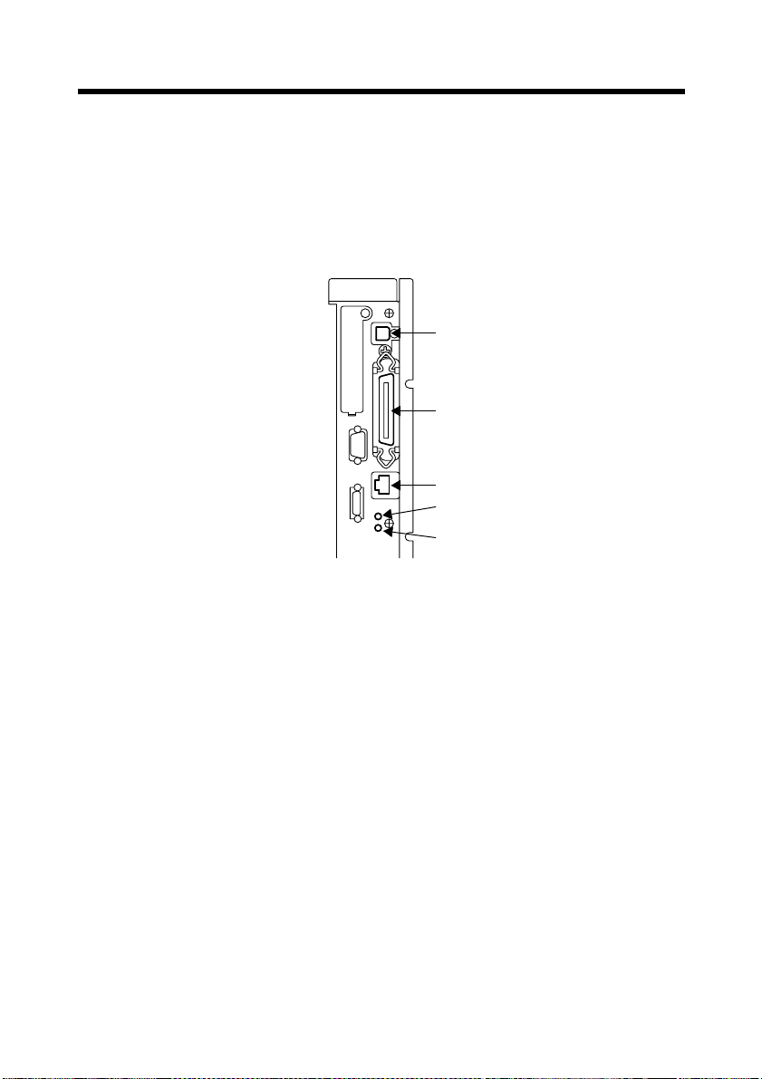
2.1 Connector Locations
(1)
(2)
(3)
LED1
LED2
4334O034AA
5
(1) USB
(2) IEEE1284 (Centronics)
(3) Network
■
Connecting the Network Cable
1. Use the cable that complies with the 10Base-T or 100Base-TX standard.
Use Category 5 or 5E cables for the network cable.
2. When the cable is connected to the connector, LED1 turns ON.
[Description of the LEDs]
LED1: LINK = Lights if the network connection is established.
LED2: ACT = Blinks depending on the data reception status.
Page 15

6
2. Connecting the Cable
Page 16
3. Settings Required for Local Connection
T o make a local connection between the PC and printer controller , mak e the settings
by following the procedures given below.
3.1 Installing the Printer Driver
For Windows 98, 98SE and Me:
The following procedure applies to the installation of the printer driver for W indows
98.
NOTE
To connect the copier to a PC, in which Windows 98, 98SE, or Me is installed,
through the USB, it is necessary that the USB device driver be installed in the
PC.
For the procedure to install the USB device driver, see “Installing through Plug
and Play” and “Connecting the USB Cable.” ☞p.15
1. Click the “Start” button and, from the menu that will then appear, select
“Settings” – “Printers.”
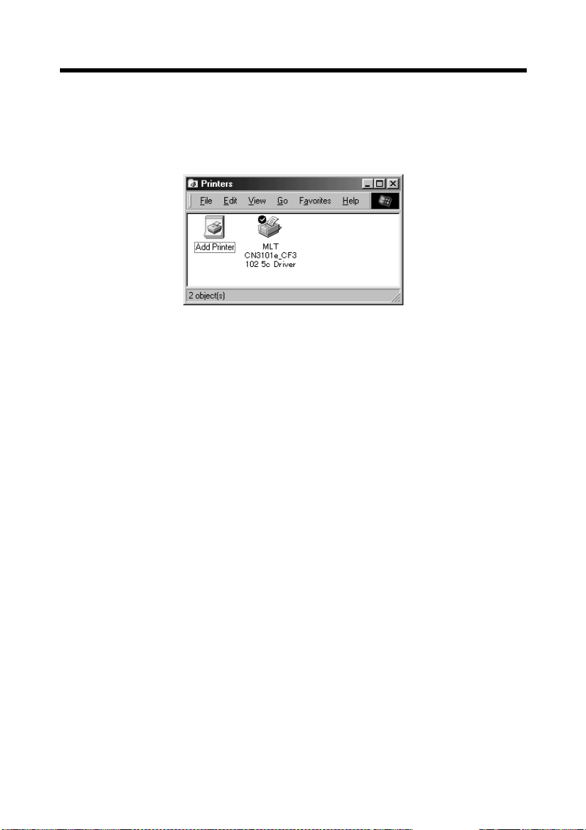
2. The Printers window will appear.
Double-click the “Add Printer” icon in the window.
7
3. The “Add Printer Wizard” will start.
Click the “Next>” button.
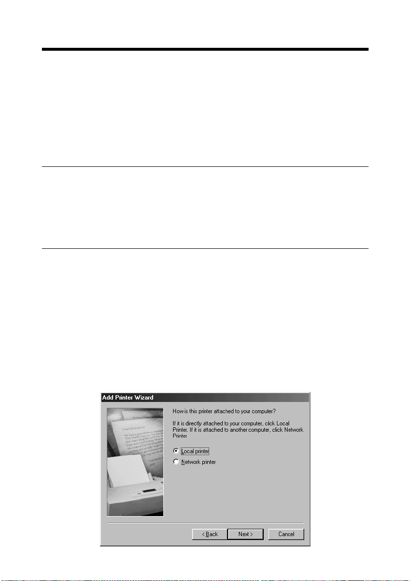
4. A window will appear, asking how the printer is to be connected.
Select “Local printer” and then click the “Next>” button.
4668P004CA
Page 17
8
3. Settings Required for Local Connection
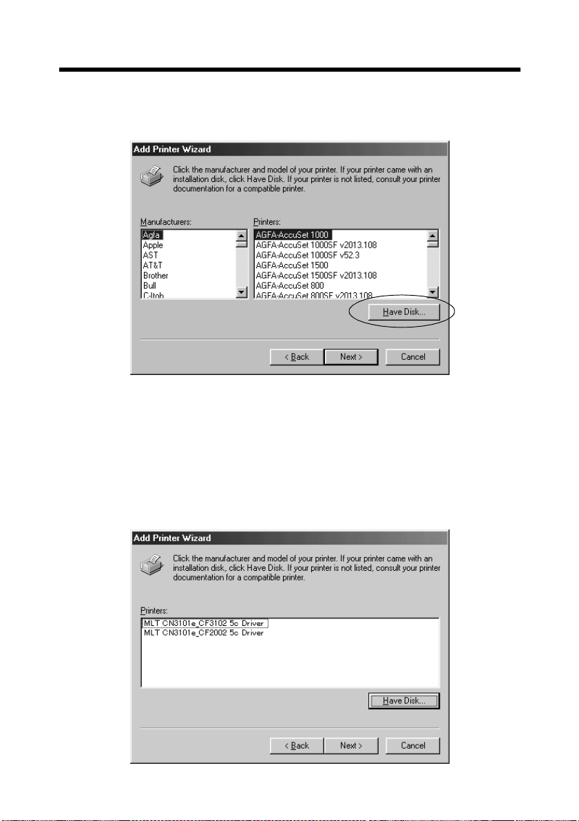
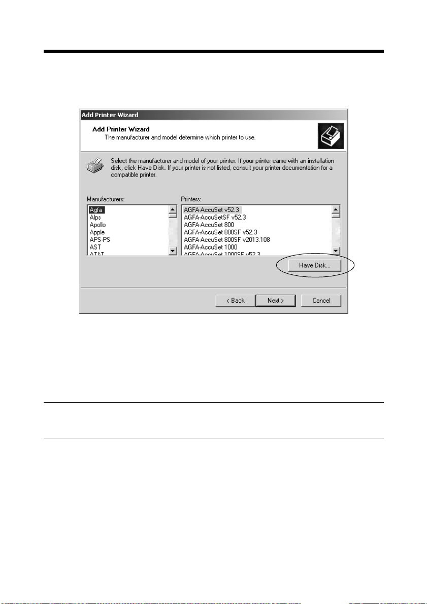
5. A window will appear, prompting you to select the manufacturer and model of
your printer.
Click the “Have Disk..” button on the lower right part of the screen.
4668P005CA
6. The “Install From Disk” dialog box will appear.
Insert the Printer Driver CD-ROM, which comes with the controller, in the CDROM drive of your PC.
7. Specify the storage of the printer driver for Windows 98/98SE/Me in the CDROM to the “Copy manufacturer’s files from:” box, then click the “OK” button.
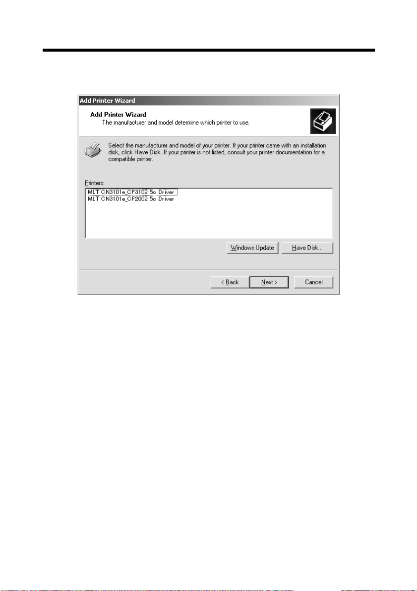
8. A “Printers” list will ap pear.
Select the printer driver to be installed and click the “Next>” button.
4334P158CA
Page 18
3. Settings Required for Local Connection
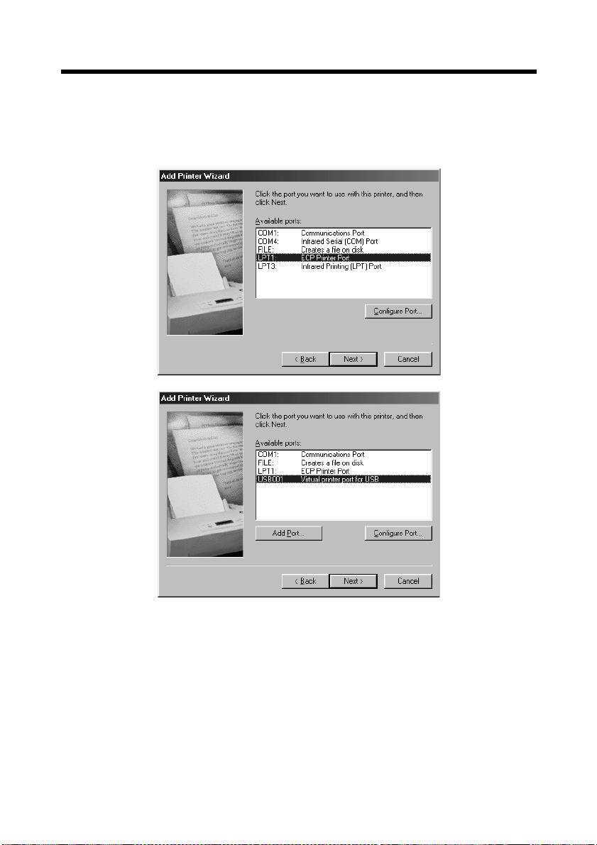
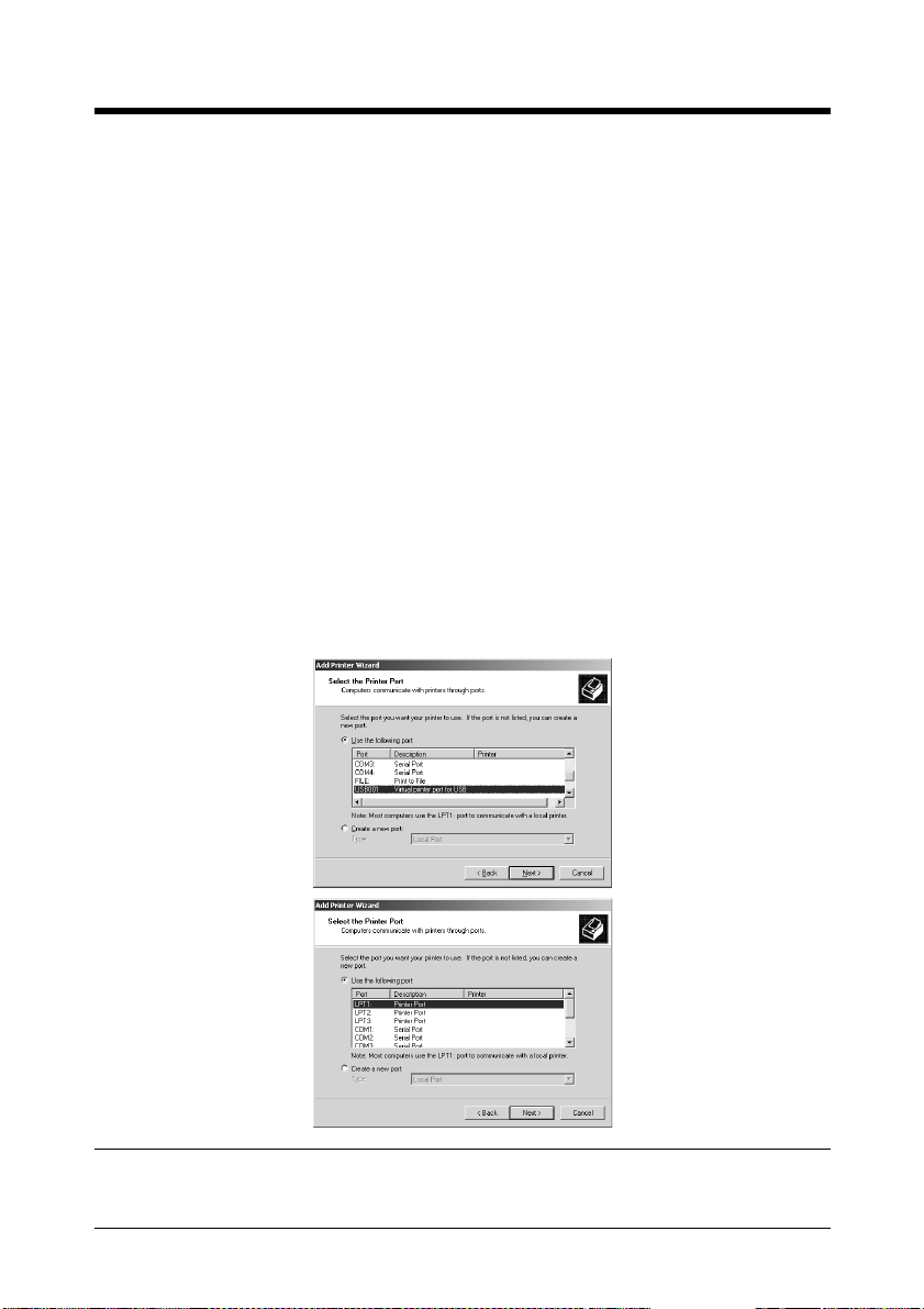
9. A window that prompts you to select the port will appear.
Select “EPUSB1” if the connection is made throu gh the USB cable a nd “LPT1”
if the connection is made through the IEEE1284 cable. Then, click the “Next>”
button.
4668P009CA
9
4334P227CA
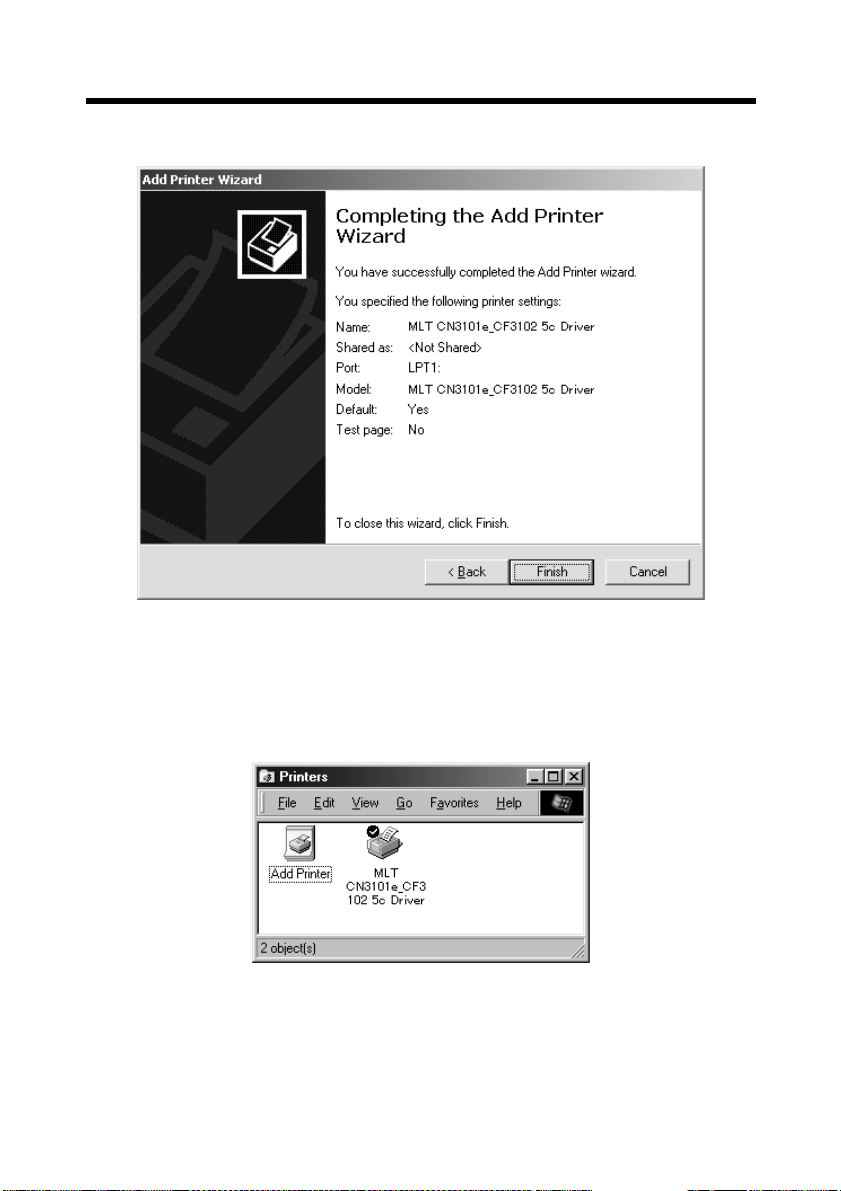
10.A window that asks you to confirm the printer name will appear.
Check the printer name.
“MLT CN3101e_CF3102 5c Driver” or “MLT CN3101e_CF2002 5c Driver”
If you want to designate this printer as the default printer, select “Yes.”
Click the “Next>” button.
11.A screen that allows you to select printing of a test page will appear.
If you want to print a test page, select “Yes.”
Page 19
10
3. Settings Required for Local Connection
12.Installation will complete.
When all the files hav e b een copied f rom the CD-ROM, the corresponding icon will
be added to the “Printers” window.
This completes the installation.
4334P159CA
Page 20
11
3. Settings Required for Local Connection
For Windows 2000, NT 4.0, and XP:
The following procedure applies to the installation of the printer driver for W indows
2000. Note that different names are used for the Windows NT users and different
contents of displays are given for the Windows XP users.
1. Click the “Start” button and, from the menu that will then appear, select
“Settings” – “Printers.”
2. The Printers window will appear.
Double-click the “Add Printer” icon in the window.
3. The “Add Printer Wizard” will start.
Click the “Next>” button.
4. A screen that allows you to select the type of connection made of the printer will
appear.
Select “Local printer” and then click the “Next>” button.
5. A window that prompts you to select the port will appear.
Select “USB001” if the connection is made through the USB cable and “LPT1”
if the connection is made through the IEEE1284 cable. Then, click the “Next>”
button.
NOTE
Windows NT 4.0 does not support USB.
4334P228CA
4668P021CA
Page 21
12
3. Settings Required for Local Connection
6. A window will appear, prompting you to select the manufacturer and model of
your printer.
Click the “Have Disk..” button on the lower right part of the screen.
4668P022CA
7. The “Install From Disk” dialog box will appear.
Insert the Printer Driver CD-ROM, which comes with the printer controller, in
the CD-ROM drive of your PC.
8. Specify the storage of the printer driver for Windows NT or 2000 in the CDROM to the “Copy manufacturer’s files from:” box, then click the “OK” button.
MEMO
For Windows XP users, use the printer driver for Windows 2000.
Page 22
3. Settings Required for Local Connection
9. A “Printers” list will ap pear.
Select the printer driver to be installed and click the “Next>” button.
13
4334P161CA
10.A window that asks you to confirm the printer name will appear.
Check the printer name.
“MLT CN3101e_CF3102 5c Driver ” or “MLT CN3101e_CF2002 5c Driver ”
If you want to designate this printer as the default printer, select “Yes.”
Click the “Next>” button.
11.A screen that allows you to select whether to share the printer or not.
If you share the printer with other users, select “Shared” and type the share
name in the box to the right of “Share Name.”
If not, select “Do not share this printer” and then click the “Next>” button.
12.A screen that allows you to select printing of a test page will appear.
If you want to print a test page, select “Yes.”
Page 23
14
3. Settings Required for Local Connection
13.As the last step, click the “Finish” button.
4334P162CA
14.Installation will complete.
When all the files hav e b een copied f rom the CD-ROM, the corresponding icon will
be added to the “Printers” window.
This completes the installation.
4334P159CA
Page 24

15
3. Settings Required for Local Connection
Installation through Plug and Play
If the local connection (IEEE1284 or USB) is made between the PC and the copier,
the printer driver can be installed through the “Plug and Play” function.
For details of how to install the printer driver, see “3. Setting Req uired for Local
Connection.” ☞p.7
NOTE
Windows NT 4.0 does not support “Plug and Play.”
■
Connecting the IEEE1284 (Centronics) Cable
1. Make the connection after the copier and PC have been turned OFF.
2. Plug one end of the cable into the printer controller and fix the lock springs on
both sides of the connector.
3. Connect the other end of the cable to the PC.
4. The copier and PC are turned ON in that order.
Windows is started, the installation guide for the printer driver through Plug and
Play is automatically started on the PC.
5. Install the printer driver according as instructed by the “Add New Hardware
Wizard.”
■
Connecting the USB Cable
• Windows 98, 98SE and Me:
Following the instructions given in the “Add New Hardware Wizard” that will be
automatically started through Plug and Play, install the USB device driver and then
install the printer driver.
1. Connect the USB cable to the copier and PC with the Power Switch ON.
2. The installation of the printer driver through Plug and Play is automatically
started on the PC.
3. Install the USB device driver according as instructed by the “Add New
Hardware Wizard.”
NOTE
The USB device driver is stored in the printer driver CD-ROM.
4. Following the instructions given in the “Add New Hardware Wizard” that will
automatically appear after the USB device driver has been installed, install the
printer driver.
Page 25
16
3. Settings Required for Local Connection
• Windows 2000 and XP:
1. Connect the USB cable to the copier and PC with the Power Switch ON.
2. The installation of the printer driver through Plug and Play is automatically
started on the PC.
3. Install the printer driver according as instructed by the “Add New Hardware
Wizard.”
NOTE
Windows NT 4.0 does not support USB.
Local Interface Setting
If necessary, set the local interface on the copier control panel.
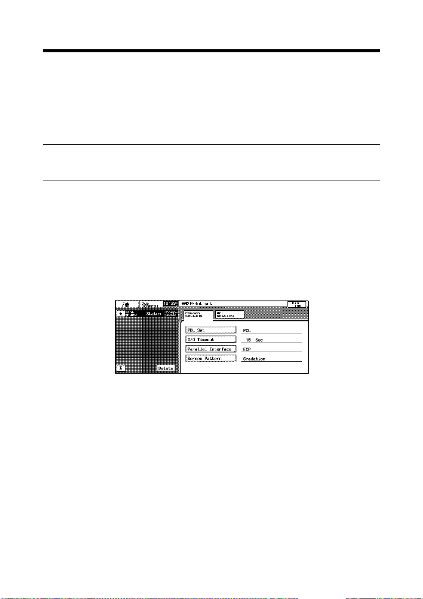
1. On the control panel of the copier, select “Utility” – “Admin. Mode” and then
enter the password.
2. Select “Print Set” – “Common Setting.”
4334P151CA
3. Make the following settings.
I/O Timeout : Set the communications timeout (10 to 300 sec.).
Parallel Interface : Set the mode for use of parallel interface
(Compatible, Nibble, ECP).
Page 26

17
4. Settings Required for Network Printing
This chapter explains the settings that need to be made for network printing.
Make the necessary settings for network printing by following the procedures given
below.
1. Referring to “3. Settings Req uired for Local Connect ion,” ins tall th e prin ter
driver. ☞p.7
At this time, select “LPT1” for the port.
NOTE
Do not execute a test print at this time.
Do that after the network connections and settings have been made.
2. Following the instructions given in this chapter, make the necessary settings for
network printing.
Change the port of the printer driver installed in step 1 to one for the network
connection and change the settings on the controller side as may become
necessary.
NOTE
For the IPP connection, it is necessary to start with the step to add the printer
driver.
4.1 Network Connection That Can be Selected in Each of
Different Windows OSs
Different setting pr ocedures apply depen ding on the output method (LP R, W indo ws
Printing, IPP).
Select the connection scheme optimum for the operating environment.
LPR
Windows
Printing
IPP
Windows
98,98SE
❍❍❍❍❍
Windows MeWindows
NT4.0
❍❍❍
Windows
2000
❍❍
Windows
XP
Protocol Used
TCP/IP
NetBEUI
TCP/IP
Page 27

18
4. Settings Required for Network Printing
4.2 To Make the Settings on the Controller Side
Network settings on the controller side may be made either from the copier control
panel or through PageScope Light used on a PC connected to the network. Use of
PageScope Light allows detailed settings that cannot be made from the copier
control panel to be made. For the details of PageScope Light, see “Appendix B.
How to Use PageScope Light.” ☞p.138
To use PageScope Light, it is necessary to first set the IP address by following the
procedure given below.
IP Address Setting
1. On the control panel of the copier, select “Utility” – “Admin. Mode” and then
enter the password.
2. Select “Network set” – “Common Setting” – “TCP/IP” to open the “TCP/IP”
screen.
4334P152CA
3. Make the following settings:
IP Address : Set the IP address of the controller.
Subnet Mask : Set the subnet mask for the network to be
connected.
Gateway Address : Set the default gateway address for the network to
be connected.
Check with the network administrator on these three items in advance.
4. Turn OFF the Power Switch OFF of the copier.
Turn the Power Switch ON again, then the settings are effective.
Page 28

19
4. Settings Required for Network Printing
■
Accessing PageScope Light
PageScope Light can be accessed directly using a Web browser.
1. Start the Web browser.
2. Type the IP address of the controller as follows in the address box and press the
Enter key.
http://<controller IP address>/
E.g.: If the controller IP address is 172.16.0.100
http://172.16.0.100/
3. PageScope Light will appear.
For the details of PageScope Light, see “Appendix B. How to Use PageScope
Light.” ☞p.138
Page 29
20
4. Settings Required for Network Printing
4.3 Windows Printing Setting
The use of Windo ws Printing enables direct printing over the Microsof t network .
NOTE
To make the Windows Printing setting, it is necessary to install the NetBEUI
protocol in the PC.
Settings made on the controller side
Make the settings for Windows Printing from PageScope Light. The setting is
necessary fo r Windows Printing.
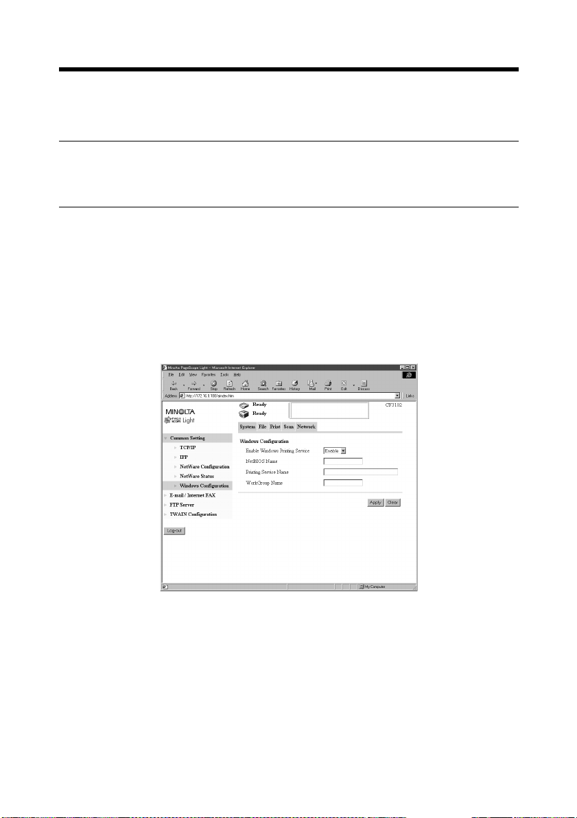
1. Start PageScope Light.
2. Enter the password to log on to the Administrator mode.
3. Click the “Network” tab and then select “Common Setting” – “Windows
Configuration.”
4. Make the following settings.
Enable Windows Printing Service:
Set the Windows print service.
Setting values : Enable, Disable
NetBIOS Name : Set the NetBIOS name.
Setting value : 15 alphanumeric characters or less
Printing Service Name : Set the print service name.
Setting value : 13 alphanumeric characters or less
WorkGroup Name : Set the work group name.
Setting value : 15 alphanumeric characters or less
4334P156CA
Page 30

21
4. Settings Required for Network Printing
Settings made on the Printer Driver side
• Windows 98, 98SE and Me:
1. Click the “Start” button and, from the menu that will then appear, select
“Settings” – “Printers.” Select the icon of the printer that has been installed;
then, right-click it and choose “Properties.”
2. On the “Details” tab, click the “Add Port” button.
3. Select “Network” and click the “Browse” button. On th e network configuration
that will then be displayed, select the target printer icon.
• Windows NT 4.0, 2000 and XP:
1. Click the “Start” button and, from the menu that will then appear, select
“Settings” – “Printers.” Select the icon of the printer that has been installed;
then, right-click it and choose “Properties.”
2. Select the “Port” tab. Then, select “Add Port” – “Local Port” and type the
\\NetBIOSname\PrintingService name.
3. Click the “OK” button to exit the function.
4. For the NetBIOS name and the Printing Service name to be entered, click the
“Network” tab of PageScope Light and see “Windows Configuration” by
selecting “Common Setting” – “Windows Configuration.”
Page 31

22
4. Settings Required for Network Printing
4.4 Settings for Printing through LPR
The following explain how to make settings for printing through LPR in different
OSs.
Settings made on the controller side
Set the IP address in the controller. ☞p.18
Settings made on the Printer Driver side
• Windows NT 4.0:
1. Click the “Start” button and, from the menu that will then appear, select
“Settings” – “Printers.” Select the icon of the printer that has been installed;
then, right-click it and choose “Properties.”
2. Select the “Port” tab and click the “Add Port..” button.
3. From the “Available port types” list, select “LPR Port” and then click “New
Port.”
NOTE
If “LPR Port” is not available in the list, click the “Start” button and select
“Control Panel” – “Network.” Click the “Services” tab, click the “Add” button,
and install the Microsoft TCP/IP print service.
4. On the “Add LPR compatible printer” dialog box, type the IP address of the
printer in the “Name or address of server providing lpd:” field.
Type “Print” in the “Name of printer or print queue on that server” field.
5. When the setting has compl eted, carry o ut the test p rint.
• Windows 2000 and XP:
1. Click the “Start” button and, from the menu that will then appear, select
“Settings” – “Printers.” Select the icon of the printer that has been installed;
then, right-click it and choose “Properties.”
2. Select the “Port” tab and click the “Add Port..” button.
3. From the “Available port types” list, select “Standard TCP/IP Port” and then
click “New Port.”
4. Type the IP address of the printer in the “Name of printer or IP address” field.
5. Select “Custom” and click “Setting.”
6. Select “LPR.”
7. Type “Print” in the “Queue Name” field and click “OK.”
8. Click “Next” and then “Finish” to exit from the dialog box.
Page 32

4. Settings Required for Network Printing
4.5 Settings for Printing using IPP
Settings made on the controller side
If IPP (Internet Printing Protocol) is used, make the following settings on
PageScope Light. (Printing can be done with the default settings.)
1. Start PageScope Light.
2. Enter the password to log on to the Administrator mode.
3. Click the “Network” tab and then select “Common Setting” – “IPP.”
4. Make the following settings.
23
4334P235CA
Enable IP P : Set the IPP func tion.
Setting values : Enable, Disable
Accept IPP Jobs : Set the IPP reception function.
Setting values : Enable, Disable
Printer URI : Displays the URL of the print er, with which data
can be print ed using IPP.
Operational Supported : Specify the print operation supported by the IPP.
Setting values : Print Job, Validate Job, Cancel Job, Get Job
Attributes, Get Jobs, Get Printer Attributes
Page 33

24
4. Settings Required for Network Printing
Furthermore, make settings as they relate to IPP printing.
1. Click the “Print” tab and then select “IPP.”
2. Make the following settings.
4334P154CA
Printer Name : Set the printer name.
Setting value : 127 alphanumeric characters or less
Printer Location : Set the installed site of the printer.
Setting value : 127 alphanumeric characters or less
Printer Manufacturer and Model:
Set the manufacturing information of the printer.
Setting value : 127 alphanumeric characters or less
Page 34

25
4. Settings Required for Network Printing
Settings made on the Printer Driver side
• Windows 2000 and XP:
1. Click the “Start” button and, from the menu that will then appear, select
“Settings” – “Printers.” Start the printer addition wizard and select “Network
printer.”
2. Select the “Locate Your Printer” tab and then select “Connect to a printer on the
Internet or on your intrernet.”
3. Type http://“IP address”/ipp in the “URL” field.
4. Insert the printer driver CD-ROM in the CD-ROM drive.
5. On the screen for selecting the manufacturer and model of your printer, click the
“Have Disk..” button.
6. Click the “Browse..” button and specify where the printer driver is from the CDROM.
NOTE
For Windows XP users, use the printer driver for Windows 2000.
7. Make sure that “MLT CN3101e_CF3102 5c Driver” or “MLT
CN3101e_CF2002 5c Driver” appears in the printer list. Then, click “Next>.”
8. Change the default printer setting and printer name as necessary. Then, carry
out the test print.
Page 35

26
4. Settings Required for Network Printing
4.6 Print Service Setting in NetWare
■
Print settings on the PC from w hich printing is effected
The controller supports the following environment.
NetWare Version Protocol Emulation Service Mode
NetWare 3.2 IPX Bindery PServer/Rprinter
NetWare 4.x IPX NDS,
Bindery emulation
NetWare 5.x IPX,
TCP/IP
■
NetWare Server Setting Procedure
• NetWare 3.2 print server mode settings
1. Log on to the NetWare server, in which PServer is to be registered, by the
Supervisor right.
2. Start Pconsole .
3. Select “Print Queue Information” from “Available Options” and then press
“Enter.”
4. Click “Insert,” type “Print Queue Name,” and press “Enter” to r e gister the [p rint
queue name].
5. Press “Esc” to return to “Available Options.”
6. Select “Print Server Information” and press “Enter.”
7. Press “Insert,” type “Print server name” in “New print server name,” and click
“Enter” to register the [print server name].
8. Select the print server, which has been created, and press “Enter” to display the
“Print Server Information” menu.
9. Select “Print Server Configuration” from the “Print Server Information” menu
to display the “Print Server Configuration Menu.”
10.Select “Printer Configuration” and press “Enter” to display the “Configured
Printers” list.
11.Select “Not Installed” at the top row and press “Enter” to display “Printer 0
configuration.”
12.Change the printer name in the “Name” column to “CN3101e” and press
“Enter” to validate the change.
13.With the “Type” column selected, press “Enter.” Then, select “Remote Parallel/
LPT1” and press “Enter” to validate the selection.
14.Press “Esc” to save the settings.
15.Press “Esc” once again to return to “Print Server Configuration Menu.”
NDS PServer/NDPS
PServer/Nprinter
(lpr)
Page 36

27
4. Settings Required for Network Printing
16.Select “Queues Serviced by Printer” and press “Enter.”
17.Select “CN3101e” created in step 12 from the “Defined printer” list and press
“Enter.”
18.Press “Insert” to display the “Available Queue” list of the printer.
19.Select the print queue prepared in step 4. Specify priority using a corresponding
number, 1 being the t op priorit y and 10 bei ng the lo w est. Then , press “Ent er” to
validate the selection.
20.Press “Esc” to quit Pconsole.
* For the queue user rights, printer notification option, assignment of multiple
queues, and password, see the document available for NetWare and set them as
necessary.
21.Using PageScope Light, set the controller as detailed below and restart it.
4334P237CA
Details of Setting:
Enable NetWare : Enable
Frame T ype : Auto Detect (Select the frame type according to the
network environment.)
Bindery/NDS : Bindery
Print Server Name : Print server name created in step 7
Print Server Password : (Set only when the password is set on the NetWare
server side.)
Preferred File Server : Name of the file server to which PServer is
connected
Print Queue Scan Rate : 1 (Change as necessary.)
Mode : PServer
22.At the NetWare server console, load MONITOR.NLM.
23.Select “Connection Information” and check that the PServer created is
Page 37

28
4. Settings Required for Network Printing
connected in the active connection column.
Page 38

29
4. Settings Required for Network Printing
• NetWare 3.2 remote printer mode settings
1. Log on to the NetWare server, in which PServer is to be registered, by the
Supervisor right.
2. Start Pconsole .
3. Select “Print Queue Information” from “Available Options” and then press
“Enter.”
4. Click “Insert,” type “Print Queue Name,” and press “Enter” to r e gister the [p rint
queue name].
5. Press “Esc” to return to “Available Options.”
6. Select “Print Server Information” and press “Enter.”
7. Press “Insert,” type “Print server name” in “New print server name,” and click
“Enter” to register the [print server name].
8. Select the print server, which has been created, and press “Enter” to display the
“Print Server Information” menu.
9. Select “Print Server Configuration” from the “Print Server Information” menu
to display the “Print Server Configuration Menu.”
10.Select “Printer Configuration” and press “Enter” to display the “Configured
Printers” list.
11.Select “Not Installed” at the top row and press “Enter” to display “Printer 0
configuration.”
12.Change the printer name in the “Name” column to “CN3101e” and press
“Enter” to validate the change.
13.With the “Type” column selected, press “Enter.” Then, select “Remote Parallel
LPT1” and press “Enter” to validate the selection.
14.Press “Esc” to save the settings.
15.Press “Esc” once again to return to “Print Server Configuration Menu.”
16.Select “Queues Serviced by Printer” and press “Enter.”
17.Select “CN3101e” created in step 12 from the “Defined printer” list and press
“Enter.”
18.Press “Insert” to display the “Available Queues” list of the printer.
19.Select the print queue prepared in step 4. Specify priority using a corresponding
number, 1 being the t op priorit y and 10 bei ng the lo w est. Then , press “Ent er” to
validate the selection.
20.Press “Esc” to quit Pconsole.
21.At the NetWare server console, load PSERVER.NLM.
* For the queue user rights, printer notification option, assignment of multiple
queues, and password, see the document available for NetWare and set them as
necessary.
Page 39

30
4. Settings Required for Network Printing
22.Using PageScope Light, set the controller as detailed below and restart it.
4334P163CA
Details of Setting:
Enable NetWare : Enable
Frame T ype : Auto Detect (Select the frame type according to the
network environment.)
Bindery/NDS : Bindery
Print Server Name : Print server name created in step 7
Print Server Password : (Set only when the password is set on the NetWare
server side.)
Mode : Nprinter/Rprinter
Printer Number : 255 (Set 255 or the numbers (0-15) assigned to the
printer.)
23.At the NetWare server console, display the print server screen and check that
“CN3101e” (created printer) is in the status of “Waiting for job” with printer 0
connected to it.
Page 40

31
4. Settings Required for Network Printing
• NetWare 4.x NDS print server mode settings
1. Log on to the NDS Tree by the Administrator right.
2. Start NWADMIN.
3. Select the container object, either Organization or Organizational Unit, that
offers the print service and select “Print Service Quick Setup” from the tool
menu.
4. Type “Print serv er name,” “Printer name,” “Print Queue Name,” and “Volume.”
Then, set “Remote Other/Unknown” for the “Type” name of the printer and save
the settings.
* For the queue user rights, printer notification option, assignment of multiple
queues, and password, see the document available for NetWare and set them as
necessary.
5. Using PageScope Light, set the controller as detailed below and restart it.
4334P164CA
Details of Setting:
Enable NetWare : Enable
Frame T ype : Auto Detect (Select the frame type according to the
network environment.)
Bindery/NDS : NDS
Print Server Name : Print server name created in step 4
Page 41

32
4. Settings Required for Network Printing
Print Server Password : (Set only when the password is set on the NetWare
server side.)
Preferred NDS Context : Name of the context to which PServer is connected
Preferred NDS Tree : Name of the tree to which PServer logs on
Print Queue Scan Rate : 1 (Change as necessary.)
Mode : PServer
6. At the NetWare server console, load MONITOR.NLM.
7. Select “Connection Information” and check that the PServer created is
connected in the active connection column.
Page 42

33
4. Settings Required for Network Printing
• NetWare 4.x NDS remote printer mode settings
1. Log on to the NDS Tree by the Administrator right.
2. Start NWADMIN.
3. Select the container object, either Organization or Organizational Unit, that
offers the print service and select “Print Service Quick Setup” from the tool
menu.
4. Type “Print Serv er Name,” “Printer name,” “Print Queue Name,” and “V olume. ”
Then, set “Remote Other/Unknown” for the “Type” name of the printer and save
the settings.
* For the queue user rights, printer notification option, assignment of multiple
queues, and password, see the document available for NetWare and set them as
necessary.
5. Using PageScope Light, set the controller as detailed below and restart it.
4334P165CA
Details of Setting:
Enable NetWare : Enable
Frame T ype : Auto Detect (Select the frame type according to the
network environment.)
Bindery/NDS : NDS
Print Server Name : Print server name created in step 4
Page 43

34
4. Settings Required for Network Printing
Print Server Password : (Set only when the password is set on the NetWare
server side.)
Preferred NDS Context : Name of the context in which PServer is loaded
Preferred NDS Tree : Name of the tree in which PServer is loaded
Print Queue Scan Rate : 1 (Change as necessary.)
Mode : Nprinter/Rprinter
Printer Number : 255 (Set 255 or the numbers (0-254) assigned to the
printer.)
6. At the NetWare server console, load PSERVER.NLM.
7. At the NetWare server console, display the print server screen and check that
“CN3101e” (created printer) is in the status of “Waiting for job” with printer 0
connected to it.
NetWare 4.x supports both the NDS and bindery emulation.
NOTE
To use bindery emulation, check that bindery emulation is enabled in the
NetWare server.
Page 44

35
4. Settings Required for Network Printing
• NetWare 5.x NDS print server mode settings
* To use the print server mode, it is necessary that the IPX protocol have been
loaded in the NetWare server.
1. Log on to the NDS Tree by the Administrator right.
2. Start NWADMIN.
3. Select the container object, either Organization or Organizational Unit, that
offers the print service and select “Print Service Quick Setup” from the tool
menu.
4. Type “Print Se v er Name,” “Printer name,” “Print Queue Name,” and “Volume. ”
Then, set “Remote Other/Unknown” for the “Type” name of the printer and save
the settings.
* For the queue user rights, printer notification option, assignment of multiple
queues, and password, see the document available for NetWare and set them as
necessary.
5. Using PageScope Light, set the controller as detailed below and restart it.
4334P166CA
Details of Setting:
Enable NetWare : Enable
Frame T ype : Auto Detect (Select the frame type according to the
network environment.)
Bindery/NDS : NDS
Print Server Name : Print server name created in step 4
Page 45

36
4. Settings Required for Network Printing
Print Server Password : (Set only when the password is set on the NetWare
server side.)
Preferred NDS Context : Name of the context to which PServer is connected
Preferred NDS Tree : Name of the tree to which PServer logs on
Print Queue Scan Rate : 1 (Change as necessary.)
Mode : PServer
6. At the NetWare server console, load MONITOR.NLM.
7. Select “Connection Information” and check that the PServer created is
connected in the active connection column.
Page 46

4. Settings Required for Network Printing
• NetWare 5.x Novell Distributed Print Service (NDPS) settings
* Before making settings for NDPS, make sure that the NDPS Broker and NDPS
Manager have been created and loaded.
* Before starting the procedure, make sure that the TCP/IP protocol has been set
in the NetWare server and an IP address has been assigned to the con tr oller, and
started, using PageScope Light.
37
4334P153CA
Creating the NDPS Printer Agent
1. Log on to the NDS Tree by the Administrator right.
2. Start NWADMIN.
3. Right-click the “Organization Unit” container under “Organization,” in which
the printer agent is created. From “Create,” select “NDPS Printer.”
4. Type the “Printer Name” in the “NDPS Printer Name” column.
5. Select “Create a New Printer Agent” in the “Printer Agent Source” column and
click “Create.”
6. Check the printer agent name and, in the “NDPS Manager Name” column,
browse through NDPS managers and set one.
7. Select “Novell Printer Gateway” “Gateway Types” and set it in “Gateway
Types.”
8. In the “Configure Novell PDS for Priner Agent” window, select and set
“((None))” for printer type and “Novell Port Handler” for port handler type.
9. Select and set “Remote (LPR on IP)” for “Connection Type.”
Page 47

38
4. Settings Required for Network Printing
10.Set the IP address set in the controller for the host address, type “Print” in
“Printer name,” and press “Finish” to validate the settings.
11.The printer driv er registration screen will then appear. Select “None” for all OSs
and complete the registration procedure.
* For the printer user rights, printer notification option, and assignment of
multiple queues, see the document available for NetWare and set them as
necessary.
Page 48

39
4. Settings Required for Network Printing
• Client Print Setting
Click “Start” – “Settings” – “Printers” and then dou ble-clic k the “Add Printer” icon.
Refer to the network in the destination port setting and specify the queue name
previously created (NDPS printer name).
On the list of printer models, select the driver from the printer driver CD-ROM.
Complete the installation procedure according as instructed by the wizard.
Page 49

40
4. Settings Required for Network Printing
4.7 Operation Checks after Installation of Driver
Test Printing from Client PC
A test page is printed to check to see if the printer driver has been properly installed.
1. Click the “Start” button and, from the menu that will then appear, select
“Settings” – “Printers.”
2. Select the icon of the printer that h as been installed; then, right-click it and
choose “Properties.”
3. From the screen that will then appear, click the “Print Test Page” button.
4334P167CA
Page 50

41
Page 51

42
5. Uninstalling the Driver
5. Uninstalling the Driver
5.1 Uninstalling the Driver
1. Click the “Start” button and, from the menu that will then appear, select
“Settings” – “Printers.”
2. Click the icon of the printer to be deleted .
3. Select the “Delete” key to delete the driver.
4. When the uninstalli ng procedur e is co mpleted , the pr int er icon dis appears from
the “Printers” window.
This completes the uninstalling procedure.
Page 52

Advanced Operations
43
Page 53

44
Page 54

45
6. Printing
This chapter explains printing operations that can be set from the printer driver.
How to Display the Printer Driver Property Sheet
There are two approaches available for use to display the property sheet. (Each
offers different ranges of settings that can be incorporated.)
• Display ing th e property sheet from the printer folder
1. Click the “Start” button and, from the menu that will then appear, select
“Settings” – “Printers.”
2. Right-click the “MLT CN3101e_CF3102 5c Driver” or “MLT
CN3101e_CF2002 5c Driver” icon. Then, select “Properties” from the menu.
3. A property sheet will then appear. Make the setting of each item and click
“OK.”
The settings made are applicable to all printed pages produced with the copier.
• Displaying the property sheet from the application menu
1. Select “Print” from the application.
2. A print dialog box will appear. Click “Properties” beside the printer name (MLT
CN3101e_CF3102/CF2002 5c Driver should be displayed) and make the
necessary settings.
The settings are valid only in the application for which printing is specified.
Components of Property Sheet
The window of Easy Set and Printer Figure/Page Layout is displayed at all times.
4334P168CA
Page 55

46
6. Printing
Following give an overview of each function available from different tabs.
Tab Name Function Name Description
Setup N-up Print two or more pages on a sheet of paper.
Watermark Print pages with text put in the background.
Duplex/Booklet Set Duplex or Booklet function.
Paper Source Specify the paper source and the type of paper.
Output Setting Set Staple, Hole Punch, Folding or other finishing type.
Paper Original Document Size Specify the document size.
Output Paper Size Specify the output paper size.
Copies Specify the number of copies to be made.
Collate Specify an output by set.
Orientation Specify print orientation.
Quality Select Color or Grayscale Set color or monochrome.
Exposure Modes Set the color matching mode.
Use Printer Font Set use of the printer font.
Resolution Select the print resolution (600 dpi fixed)
Download as Bitmap Select the mode, in which a bitmapped font or the program (vector font) is
Glossy Mode Select the Glossy Mode
Device Option
Setting
Job Management Lock Job Specify the password for Lock Job.
Device Option Specify the options mounted on the copier.
Job Owner
(Default User Name)
Access Number
(Default Access Number)
Store to Memory Store the job in memory until it is canceled on the copier side.
Store to HDD Store the job in the hard disk until it is canceled on the copier side.
Proof and Print Print the first set only of the job and store the rest in memory.
Access Code Type the access number assigned if the Copy Track function is set on the
Distribution Print a distribution number in the background.
Ref.: Effecting N-up Printing ☞p.49
The text can be changed or edited.
Ref.: Printing Pages with Watermarks ☞p.50
Ref.: Effecting Duplex/Booklet Printing ☞p.54
Set Front Cover, Back Cover or OHP Interleaving.
Ref.: Adding a Cover or Interleaf ☞p.58
Ref.: Effecting Staple ☞p.55
Effecting Folding ☞p.56
Effecting Hole Punch ☞p.57
Set an enlarged or reduced size.
Ref.: Print to Suit the Paper Size ☞p.59
Document: Text mode
Photo: Photo mode
downloaded.
Displays the specified user name on the control panel of the copier as the
job user name.
Set the default value for the access number (i.e., default access number).
Ref.: Lock Job ☞p.123
Ref.: St o re to Memory ☞p.125
Ref.: Store to HDD ☞p.124
Ref.: Proof and Print ☞p.124
copier side.
Ref.: Transmitting a Print Job to a Copier in Which the Copy Track
Function is Active ☞p.122
Ref.: Printing Pages with a Distribution Number ☞p.123
For details of the “Job Management” tabs, see “8. Job Management.” ☞p.121
Page 56

47
6. Printing
6.1 Device Option Setting
Options installed on the copier are enabled from the printer driver.
Setting Procedure
1. Start the printer driver and select the “Device Option Setting” tab.
2. From the “Installable Options” list, select the device to be installed and click the
“Add” button.
4334P249CA
Check that the selected option is now shown under the “Installed Options” list.
6.2 Using Easy Set
The current setting value can be saved under a name you specify.
4334P241CA
Calling up settings
Click the [ ▼ ] button in the combo box and choose the desired setting from the list.
Saving or deleting settings
The contents of each property sheet may be saved or deleted.
Clicking the “Save” button will open the Easy Set Name Box.
The current setting value can be saved under a name you specify.
Page 57

48
6. Printing
6.3 Displaying Page Layout and Printer Figure
4334P242CA
• Page Layout shows a simplified image of a printed page.
• Printer Figure shows the devices mounted on the copier.
MEMO
Page Layout allows you to check how a printed page will look like before
actually printing it.
Page 58

49
6. Printing
6.4 Effecting N-up Printing
N-up printing refers to t he functi on that prin ts a document co nsisting of two or more
pages on a sheet of paper. It comes in handy for printing a large volum e of data and
reducing the number of printed pages.
Setting Procedure
1. Click the “Setup” tab.
2. In the “N-up” function, select any one of the following N-up subfunctions.
2-up 4-up 9-up 16-up
4334P033AA
When “Border Line” is selected, the boundary line of each page will be printed.
3. The printing sequence in N-up can be changed.
Click “N-up Style.” Select any one of the following functions from the dialog
box that will then appear.
Horiz. Ascending Horiz. Descending Vert. Ascending Vert. Descendi ng
4668P051CA
NOTE
Void image and image overlap may result in printing of a document that contains
pages of assorted sizes and directions.
Page Layout allows you to check the layout and printing sequence in N-up.
Page 59

50
6. Printing
6.5 Printing Pages with Watermarks
Specific text is printed in the background.
Watermark Print
4692O098BA
Setting Procedure
1. Select the “Setup” tab.
2. From the list of “W at ermark,” se lect the desired te xt to be put i n the backgro und
as a watermark.
Text : Select the word to be entered as the watermark.
<NONE>, CONFIDENTIAL, TOP SECRET,
COPY, DO NOT COPY, DRAFT, FINAL, PROOF
1st Page Only : The watermark is placed only on the first page.
Edit W atermark : Click to edit the font and position of the watermark.
NOTE
If the setting is made to have no image in the Cover function, that setting takes
precedence over Watermark and no watermark is printed on the cover.
Page Layout shows roughly how the watermark looks on the printed page.
Page 60

6. Printing
Editing the Watermark
Clicking “Edit Watermark” will allow you to edit the font and position of the
watermark.
(1)
(2)
(3)
(4)
(5)
51
4334P243CA
(1) Preview
Displays the print image.
(2) Watermark text
Select the desired watermark from the list of existing watermarks.
(3) New
Click to create new text. It will open a dialog box for setting details.
(4) Edit
Click to edit the text selected from (2). It will open a dialog box for setting
details.
(5) Delete
Click to delete the text selected from (2).
Page 61

52
6. Printing
Details Setting
(1)
(2)
(3)
(4)
(5)
(6)
(7)
(8)
(9)
4334P244CA
(1) Name
Type the name of the new watermark (consisting of up to 20 characters).
(2) String
T ype the character string to be prin ted as the w atermark (consisting of up to 127
characters).
(3) Type Face
Select the font of the watermark from among the fonts installed in the PC.
(4) Size
Specify the size of the characters (from 8 points to 200 points).
(5) Style
Specify the style of the characters.
• Bold : Prints bold characters.
• Italic : Prints italic characters.
(6) Color
Set the color applied to the characters.
(7) Shading
Specify the density of the characters.
Setting value: 5% to 100% (1% increments)
Page 62

(8) Angle: Specify the angle of characters with reference to the paper.
• Fixed Angle : Standard fixed angle provided by the printer driver.
Setting values: Horizontal, Diagonal, Vertical,
User Setting
• User Setting : W hen User Settin g is select ed fo r Fixed Angle, you can
set an arbitrary angle.
Setting value: -180 to +180 degrees
(-: clockwise; 0: horizontal;
+: counterclockwise)
(9) Position: Specify the position of the watermark.
• Center : Watermark is printed at the center of the paper.
• User Setting : The position is defined by the numeric values entered in
the Horizontal and Vertical boxes.
Setting value
Horizontal: -999 to 999 points
Vertical: -999 to 999 points
(1 point increments; 72 points = 1 inch)
“Position” defines the distance from the center. Positive in the horizontal
direction is rightward and positive in the vertical direction is upward.
Preview allows you to view the settings.
53
6. Printing
Page 63

54
6. Printing
6.6 Effecting Duplex/Booklet Printing
A document can be printed onto both sides of a sheet of paper or into a booklet
format (two facing pages). This function can be used only when the copier is
equipped with an Automatic Duplex Unit.
Duplex Printing
Top Binding
Print data Printout
Print data Printout
Left Binding
4608O008AA
4608O009AA
Booklet Printing
Print data Printout
4608O011AB
Setting Procedure
1. Select the “Setup” tab.
2. In the “Duplex/Booklet” function, select any one of the following subfunctions.
Off : Function disabled
Top Binding : Images are printed on both sides of a single sheet of
paper so that the top edge is the file margin.
Left Binding : Images are printed on both sides of a single sheet of
paper so that the left edge is the file margin.
Booklet Left Binding : Images of four pages are printed on both sides of a
single sheet of paper so that the printout may be folded
at its center to form a booklet bound at its left edge.
Booklet Right Binding: Images of four pages are printed on both sides of a
single sheet of paper so that the printout may be folded
at its center to form a booklet bound at its right edge.
NOTE
Void image and image overlap may result in printing of a document that contains
pages of assorted sizes and directions.
Page Layout allows you to view the result of layout by Duplex/Booklet.
Page 64

55
6. Printing
6.7 Effecting Staple
The Staple function can be used only when the copier is equipped with the Finisher
FN-8 or FN-116.
1. Select the “Setup” tab.
2. Clicking “Detail of Output Setting” will open a dialog box for setting details.
Make the following settings in the “Staple” column.
• If FN-8 is mounted:
OFF, Corner, Top Side 2 Points, Left Side 2 Points, Auto 2 Points
• If FN-116 is mounted:
OFF, Corner
NOTE
• When the FN-116 is mounted, stapling can be made up to 30 sheets of paper.
• When the FN-8 is mount ed, stapling can be made up to 50 sheets of A4
lengthwise (Letter lengthwise) paper or 25 sheets of B4 lengthwise (Legal
lengthwise) paper.
Page 65

56
6. Printing
6.8 Effecting Folding
Folding is used in combination with Booklet to produce a booklet through center
folding and center stapling. It can be used only when the copier is equipped with
the Finisher FN-8.
Setting Procedure
1. Select the “Setup” tab.
2. Clicking “Detail of Output Setting” will open a dialog box for setting details.
Make the following settings in the “Folding” column.
OFF : Disables folding.
Crease + Center Staple : Produces a booklet through center folding and center
stapling.
NOTE
No folding can be effected if the number of prints to be made at once exceeds 10.
Page 66

6. Printing
6.9 Effecting Hole Punch
The Hole Punch function can be used only when the copier is equipped with the
Finisher FN-8.
Setting Procedure
1. Select the “Setup” tab.
2. Clicking “Detail of Output Setting” will open a dialog box for setting details.
Make the following settings in the “Punch” column.
OFF, Top Side Punch, Left Side Punch, Auto Punch, Punch Holes: 2, 3, 4
NOTE
For customers in inch areas:
When effecting Hole Punch, select “2” or “3” for “Punch Holes” according to
your copier system configuration. No Hole Punch is effected when “4” is
selected.
For custo mers in metric areas:
When effecting Hole Punch, select “4” for “Punch Holes” according to your
copier system configuration. No Hole Punch is effected when “2” or “3” is
selected.
57
Page 67

58
6. Printing
6.10 Adding a Cover or Interleaf
A front cover and/or a back cover can be added to each of your copy sets.
When printing on sheets of OHP transparencies, an interleaf can also be inserted
between sheets of OHP transparencies.
Setting Procedure
1. Select the “Setup” tab.
2. In the “Paper Source” function, clicking “Detail of Paper Source” will open a
dialog box for setting details.
• Cover
A front cover and/or a back cov er can be added to each of your copy sets. You can
also select to print data on the covers or leave them blank.
Front Cover Page : Enables the Cover function.
With Image : Prin ts data on the front cover.
Front Cover Page Source : Specify the paper source for the front cover
(Manual Tray, Tray 1 to 4, or LCC).
Back Cover Page : Adds a back cover.
With Image : Prin ts data on the back cover.
Back Cover Page Source : Specify the paper source for the back cover
(Manual Tray, Tray 1 to 4, or LCC).
• Interleaf (OHP Interleaving)
When printing on sheets of OHP transparencies, an interleaf can be inserted
between sheets of OHP transparencies. The interleaf may be left blank or ha ve the
same data printed on it as the OHP transparencies.
OHP Interleaving : Enables OHP Interleaving.
OHP Interleaving Paper Source:
Specify the paper source for the interleaves (Tray 2
to 4, or LCC).
NOTES
• Select “1” for “Copies” when using OHP Interleaving.
• The paper source for OHP transparencies is Manual Tray or Tray1.
• OHP Interleaving cannot be combined with Duplex.
For how to load a paper sour ce with OHP transparencies, see User Manual of the
copier.
Page 68

59
6. Printing
6.11 Print to Suit the Paper Size
The image on the document created with an application can be enlarged or reduced
when printing according to the paper size.
Print data Printout
1149O004AA
Setting Procedure
1. Select the “Paper” tab.
2. Check that “Original Document Size” represents the size of the document
created with the application.
3. For “Output Paper Size,” specify the size of the output paper.
4. If “Fit to Paper” is selected, the copier prints the image on the document to fit
nicely to the paper size selected for use.
NOTES
Make sure that the paper of the size set in “Output Paper Size” is loaded in the
copier.
Page 69

60
6. Printing
6.12 Printing on Paper from Manual Bypass Tray
The Manual Bypass Tray can be selected as the paper source for printing.
1. Select the “Setup” tab.
2. Select “Manual Feed Tray” from the “Paper Source” list.
3. Click “OK” twice to send the job.
4. Load the Manual Bypass Tray of the copier with paper.
NOTES
• Place one sheet of paper at a time.
×
• To use paper of A4, B5, or Invoice (5-1/2
crosswise on the Manual Bypass Tray.
(Touching the job displayed on the copier control panel will display
instructions on how to place the paper. Load the paper according as
instructed.)
8-1/2) size, place the paper
Page 70

7. Settings and Operations for Scan Functions
This chapter explains how to make settings for and operate the scan functions that
become usable when the controller is added.
The copier control panel or PageScope Light is used for setting. Refer to Usage of
PageScope Light on Appendix B for the procedures to start PageScope Light and
log in the administrator mode.
The following scan functions are available for use:
• File (Scan to PC) : Transfers scanned image data to the PC through
• File (Scan to FTP Server) : Transfers scanned image data to the server through
• Scan to E-mail : Transfers scanned image data as a f ile attached to e-
• File (Scan to HDD) : Captures scanned image data to the hard disk of the
• Scan to Internet FAX : Transmits and receives image data through the
The following environment is necessary to use the scan functions.
• Network environment using TCP/IP protocol
• File (Scan to PC) : The FTP server application must be installed in
• File (Scan to FTP Server): The FTP server application must be installed in
• Scan to E-mail : A mail server must be available for the network.
• Scan to Internet FAX : A mail server must be available for the network.
p.138
☞
FTP. ☞p.64
FTP. ☞p.69
mail. ☞p.86
copier. ☞p.77
Internet Fax standard. ☞p.94
the receiving PC.
the receiving PC.
When data is to be transmitted, it is necessary that
the machine on the receiving end be capable of
receiving Internet Fax.
61
Page 71

62
7. Settings and Operations for Scan Functions
7.1 Scan Settings (Basic Settings)
Make the basic settings for scan functions.
Setting from PageScope Light
1. Start PageScope Light.
2. Enter the password and log on to the Administrator mode.
3. From the “Scan” tab, select “Scan.”
4334P171CA
4. The following items can be set.
• Scan
Device Name : The characters set for this parameter is appended
before the name of the image file created with the
scan function.
Setting value : 36 alphanumeric characters or less
Color/Grayscale Compression Level: Select the compression level for images.
Setting values : High Quality, Normal, Economy
Priority Compression Method for Monochrome (PDF): MH, MMR
Priority Compression Method for Monochrome (TIFF): MH, MMR
•Send
Scanned File Separation : Set the division met hod (by page) when the
maximum size is exceeded.
p.88, ☞p.94
☞
Setting values : Yes, No
E-mail Address (From:) : Specify the e-mail address (From:) of the sender.
☞p.93, ☞p.104
Page 72

7. Settings and Operations for Scan Functions
URL Notification
URL Notification notifies, by means of e-mail, information on the location, in
which scanned data created through a scan function is stored.
The scanned data is not attached to the e-mail message.
The party that receives the e-mail message refers to the information given in the email message to access the image data storage location.
MEMO
The information does not contain the user name or password.
If you must know it to access the image data, check the administrator.
NOTE
URL Notification is enabled through the setting made for Scan to E-mail. To use
URL Notification, it is necessary to make the settings for Scan to E-mail. ☞p.86
Selectable File Format for Scanning
The format for the scanned image data can be selected from among the following.
Setting values : TIFF, PDF, JPEG
63
• Prepare the file to be transmitted according to the specified file format.
• An extension corresponding to the specified file format is assigned.
PDF format → .pdf; JPEG format → .jpg; TIFF format → .tif
NOTE
• Some file formats are not available for selection depending on the “Color
Mode” selected during scan setting.
PDF TIFF JPEG
Full Color ❍ × ❍
Gray Scale ❍ × ❍
Monochrome ❍❍×
• It is not possible to select the format for Internet Fax scanning. (The TIFF
format is fixed for transmitting.)
• In JPEG format, it will transmits the data per page by scanning more than one
document.
Example: When it scan 10 pages, 10 JPEG files are transmitted.
Page 73

64
7. Settings and Operations for Scan Functions
7.2 Scan to PC
Scan to PC is the function that transmits image data scanned by the copier to the PC
using FTP. It is necessary that the FTP server application be started on the PC side.
PC
FTP Serv e r
Application
Software
4334O001AA
1. Using PageScope Light, make the setting for One-Touch Key Registration or
One Time Registration.
The destination and IP address can be set on the One-Touch Key Registration
screen, and the destination, IP address, and other s can mod e functions can be set
on the One Time Registration screen. ☞p.110
2. On the copier control panel, specify the destination to which the scanned data is
to be transmitted.
The destination is set by selecting the key , in which One-Touch Key Registration
or One Time Registra tion has been m ade in step 1. ☞p.66
3. On the copier control panel, specify the document scan mode.
4. Press the Start key on the copier. This lets the copier scan the document and
send the scanned data to the application for reception through FTP.
5. Check the scanned data sent.
NOTE
The root folder to which the data is transferred is that specified on the
application.
It cannot be specified from the copier side.
Page 74

7. Settings and Operations for Scan Functions
Setting the FTP Application
It is the function that transmits data using following settings of FTP.
If necessary, set following by FTP application of receiving PC.
• Login Name : anoyamous
• Password : “POP3 login name” @ “IP address of the printer
controller”
How to Check the Password
1 S tart the PageScope Light, and log on to the Administrator mode.
2. Form the “Network” tab, go to “Mail/Internet FAX” – “Receive” and you
can check “POP3 login name” (Internet FAX Reception Setting ☞p.96)
•Port Number :21
65
Page 75

66
7. Settings and Operations for Scan Functions
Scan Operation
You have the choice of two scan operating procedures available selected according
to whether the one-touch key is used to specify the destination or one time key is
used.
■
Specifying the destination using a one-touch key:
1. Press the Scan key on the copier.
2. Select the “Destination” tab.
3. Select the “IndexList” key.
4. Select the target index from the index list. Touch “Enter.” (Registering Index
☞p.110)
5. Select the one-touch key which has been registered for Scan to PC.
4334P192CA
6. Set the scanning mode. (Ref.: Setting the Scanning Mode) ☞p.67
7. Specify the document. (Ref.: Specifying the Document) ☞p.67
8. Press the Start key.
MEMOS
• One-touch key registration is possible from P ag eScope Light.
• For details of one-touch key registration, see “Advance Registration of
Destinations” of chapter 7. ☞p.110
■
Specifying the destina tion using a one time key:
The destination may be set using a one time key. ☞p.115
Page 76

7. Settings and Operations for Scan Functions
Details of Scan Operation Settings
■
Setting the Scanning Mode
1. Press the Scan key on the copier.
2. Select the “Scan Mode” tab.
3. Set the following items.
Scan Size : Set the scanning size for the document.
Or, specify any given size (in mm or 1/16”).
Resolution : Select the scanning resolution.
Setting values : 600, 400, 300, 200 dpi
File Format : Select the format, with which the file to be
transmitted is stored.
Setting values : TIFF, PDF, JPEG
Color Mode : Set the scanning color mode.
Setting values : Full Color, Monochrome, Gray Scale, Auto Color
Background Remove : Set background removal.
■
Specifying the Documen t
Set the type of the document to be scanned.
1. Press the Scan key on the copier.
2. Select the “Document Set” tab.
3. Set the following items.
67
Original Direction : Set the placement direction of the document.
Setting values : Not selected (Auto detect), Portrait documents
“Place Horizontally, ” “Place vertically,” Landscape
documents “Place Horizontally,” “Place Vertically.”
Doc. Mode : Set the document mode.
Setting values : 1 , 2, Book
Mixed Original Detection: For scanning different sized documents, select
“Mixed Original Detection” key.
Separate Scan : When Separate Scan is selected, the data read by
the time “Finish” key displayed on the copier
control panel after scanning completion is selected
are dealt as a job.
Page 77

68
7. Settings and Operations for Scan Functions
■
Setting Ch ecks
It is possible to check the details of settings on the copier control panel.
• Select the “Mode Check” key.
• Check the settings of “Scan to PC.”
4334P194CA
Page 78

7. Settings and Operations for Scan Functions
7.3 Scan to FTP Server
Scan to FTP Server is the function that transmits image data scanned by the copier
to the FTP server.
PC
Scan data
Information
69
Mail server FTP server Mail server
4334O002AA
1. Using PageScope Light, register the FTP servers (up to five). ☞p.70
2. Using PageScope Light, make the setting for One-Touch Key Registration or
One Time Registration.
The destination, FTP server an d URL Notif i cation E-mail Address can be set on
the One-Touch Key Registration screen, and the destination, FTP server, URL
Notification E-mail Address, and other scan mode functions can be set on the
One Time Registration screen. ☞p.110
3. On the copier control panel, specify the destination to which the scanned data is
to be transmitted.
The destination is set by selecting the key , in which One-Touch Key Registration
or One Time Registra tion has been m ade in step 2. ☞p.74
4. On the copier control panel, specify the document scan mode.
MEMO
Even if URL Notifi ca tion has not been set duri ng O ne-Touch Key Registra t ion o r
One Time Registration on PageScope Light, it is possible to specify the URL
Notification party from the copier control panel.☞p.76
Page 79

70
7. Settings and Operations for Scan Functions
5. Press the Start key on the copier. This lets the copier scan the document and
send the scanned data to the FTP server.
If the URL notification party has been specif ied, the information on the location,
in which scanned data is stored, is transmitted by e-mail.
6. Download the scanned data from the FTP server using the FTP client software.
If URL Notification has not been specified:
Directly access the FTP server from your FTP client software an d d ownload the
data from the folder, in which the scanned data has been stored. At this time, a
user name and a password may be necessary to access the FTP server.
If URL Notification has been specified:
Refer to the information given in the e-mail message and access the location, in
which scanned data is stored. At this time, a user name and a password may be
necessary to access the FTP server.
Controller Setting
■
Registering FTP Servers
Up to five FTP servers can be registered.
Setting from PageScope Light
1. Start PageScope Light.
2. Enter the password and log on to the Administrator mode.
3. From the “Network” tab, select “FTP Server” – “FTP Server Registration.”
4334P172CA
Not registered
Registered
Page 80

71
7. Settings and Operations for Scan Functions
4. When an empty field, in which no FTP servers have previously been registered,
is selected, it will bring you to a server registration screen.
4334P173CA
5. Set the following items.
IP Address : Specify the IP address of the FTP server.
Login Name : Specify the name with which to log on to the FTP
server.
Setting value : 32 alphanumeric characters or less
Password : Specify the password with which to log on to the
FTP server.
Setting value : 64 alphanumeric characters or less
Port Number : Specify the port number of the FTP.
(The default value of “21” is generally used.)
Directory : Set the directory through which the scanned image
is stored in the FTP server.
Setting value : 128 alphanumeric characters or less (Enter “\” to
specify default folder.)
Use Proxy : Set whether to use the proxy server or not.
Setting values : Yes, No
Page 81

72
7. Settings and Operations for Scan Functions
External Server Link : Set “Enable” and double-click the IP address of the
FTP displayed on th e ser ver link screen, which w ill
access the FTP server. The server link screen can
be displayed by selecting “Filing” – “External
Server Link.”
Setting values : Yes, No
NOTE
“External Server Link” can be used only when “anonymous” is set in “Login
Name” on the FTP Server Registration screen.
Setting from the copier control panel
1. Enter the Administrato r mo de fr om th e Utility mode.
2. Select “Network set” – “FTP server.”
3. Set the IP Address, Login name, PIN#, and Directory.
Page 82

7. Settings and Operations for Scan Functions
Setting the Proxy Server
Make the following settings to use the proxy server.
Setting from PageScope Light
1. Start PageScope Light.
2. Enter the password and log on to the Administrator mode.
3. From the “Network” tab, select “FTP Server” – “FTP Server Configuration.”
73
4334P174CA
4. Set the following items.
Proxy IP Address : To use a proxy server, set the IP address of the
proxy server.
Port Number : Set the port number of the proxy server.
FTP Connection Timeout : Set the communications timeout value with the FTP
server.
Passive Mode : Set the Passive Mode
Setting values : Enable, Disable
Page 83

74
7. Settings and Operations for Scan Functions
Scan Operation
You have the choice of two scan operating procedures available selected according
to whether the one-touch key is used to specify the destination or one time key is
used.
■
Specifying the destination using a one-touch key:
1. Press the Scan key on the copier.
2. Select the “Destination” tab.
3. Select the “IndexList” key.
4. Select the target index from the index list. Touch “Enter.” (Registering Index
☞p.110)
5. Select the one-touch key which has been registered for Scan to FTP Server.
4334P195CA
6. Set the scanning mode. (Ref.: Setting the Scanning Mode) ☞p.75
7. Specify the document. (Ref.: Specifying the Document) ☞p.75
8. Press the Start key.
MEMOS
• One-touch key registration is possible from P ag eScope Light.
• For details of one-touch key registration, see “Advance Registration of
Destinations” of chapter 7. ☞p.110
■
Specifying the destina tion using a one time key:
The destination may be set using a one time key. ☞p.115
Page 84

7. Settings and Operations for Scan Functions
Details of Scan Operation Settings
■
Setting the Scanning Mode
1. Press the Scan key on the copier.
2. Select the “Scan Mode” tab.
3. Set the following items.
Scan Size : Set the scanning size for the document.
Or, specify any given size (in mm or 1/16”).
Resolution : Select the scanning resolution.
Setting values : 600, 400, 300, 200 dpi
File Format : Select the format, with which the file to be
transmitted is stored.
Setting values : TIFF, PDF, JPEG
Color Mode : Set the scanning color mode.
Setting values : Full Color, Monochrome, Gray Scale, Auto Color
Background Remove : Set background removal.
■
Specifying the Documen t
Set the type of the document to be scanned.
1. Press the Scan key on the copier.
2. Select the “Document Set” tab.
3. Set the following items.
75
Original Direction : Set the placement direction of the document.
Setting values : Not selected (Auto detect), Portrait documents
“Place Horizontally, ” “Place vertically,” Landscape
documents “Place Horizontally,” “Place Vertically.”
Doc. Mode : Set the document mode.
Setting values : 1 , 2, Book
Mixed Original Detection: For scanning different sized documents, select
“Mixed Original Detection” key.
Separate Scan : When Separate Scan is selected, the data read by
the time “Finish” key displayed on the copier
control panel after scanning completion is selected
are dealt as a job.
Page 85

76
7. Settings and Operations for Scan Functions
■
URL Notification
This function notifies the information on the location, in which scanned data is
stored, by e-mail.
• Select the notifying party using one-touch key registration.
• The party is one selected from among only those registered in one-touch key
registration with e-mail addresses.
Procedure
1. Press the Scan key on the copier.
2. Select the “Auxiliary” key to go to the “Auxiliary” screen.
3. Specify the notifying party using the corresponding one-touch key.
4. Specify the e-mail address , which autom a tically sets the function.
■
Setting Ch ecks
It is possible to check the details of settings on the copier control panel.
• Select the “Mode Check” key.
• Check the settings of “Scan to Server.”
4334P197CA
Page 86

77
7. Settings and Operations for Scan Functions
7.4 Scan to HDD
Scan to HDD is the function that sav es image data s canned by the copier in the user
directory of the hard disk built in the copier. The image data saved in the hard disk
can be download ed to t he P C usi ng P ageSc ope Lig ht. F o r managem ent o f the s a v ed
data, see “Job Operations on PageScope Light,” “Job Management” of chapter 8.
☞p.121
NOTE
The hard disk i s op tio nal . Th is f uncti on can be us ed on ly aft er th e hard disk has
been mounted on the copier.
Scan data
Information
Mail server Mail server
PC
4334O003AA
1. Using PageScope Light, create the user directory.
On the Create User directory screen, you specify the User Directory Name and
Passwor d. ☞p.78
2. Using PageScope Light, make the setting for One-Touch Key Registration or
One Time Registration.
The destination, User directory and UR L Notif ication E- mail Address can be set
on the One-Touch Key Registration screen, and the destination, User Directory,
URL Notification E-mail Address, and other scan mode functions can be set on
the One Time Registration screen. ☞p.110
3. On the copier control panel, specify the destination to which the scanned data is
to be transmitted.
The destination is set by selecting the key , in which One-Touch Key Registration
or One Time Registra tion has been m ade in step 2. ☞p.80
4. On the copier control panel, specify the document scan mode.
Page 87

78
7. Settings and Operations for Scan Functions
MEMO
Even if URL Notifi ca tion has not been set duri ng O ne-Touch Key Registra t ion o r
One Time Registration on PageScope Light, it is possible to specify the URL
Notification party from the copier control panel. ☞p.82
5. Press the Start key on the copier. This lets the copier scan the document and
save the scanned data in the hard disk.
If the URL notification party has been specif ied, the information on the location,
in which scanned data is stored, is transmitted by e-mail.
6. Download the scanned data from the hard disk. ☞p.83
If URL Notification has not been specified:
Access the user directory specified on PageScope Light and download the data
from the hard disk. At this time, a password for accessing the user directory is
required. If PUBLIC has been specified, no password is necessary.
If URL Notification has been specified:
Refer to the information given in the e-mail message and access the location, in
which scanned data is stored. At this time, a password for accessing the user
directory is required. If PUBLIC has been specified, no password is necessary.
Creating a User Directory
■
Creating Procedure
1. Start PageScope Light.
2. From the “File” tab, select “HDD Directories.”
3. Clicking the “Create” button will open the “Create User Directory” screen.
Type data in “User Directory Name” (8 alphanumeric characters or less),
“Password,” and “Retype Password” and click the “Create” button.
When you type data in “User Directory Name” with alphabet, always type in the
capital letters.
dir1 No name can be registered.
DIR1 OK
Page 88

7. Settings and Operations for Scan Functions
• “Public directory” and “user directory”
The “directory name” can be freely assigned for “User Directory”. It is the
location, in which scanned data is stored for Scan to HDD.
The contents of the “user directory” can be accessed only when the password set
upon registration is entered. The “user directory” can be created arbitrarily from a
PageScope Light screen.
The “public directory” is the location, in which scanned data is stored for Scan to
HDD and which anyone can access without needing a password. The directory
name is “PUBLIC.”
■
File Storage Life
It can set the period of storage of scanned data in the hard disk.
1. Start PageScope Light.
2. Enter the password and log on to the Administrator mode.
3. From the “File” tab, select “File Storage Life.”
4. Set the following items.
79
4334P234CA
File Storage Life : Specify the period of storage of files in the hard
disk.
Setting value : No File Time Limitation, 1 day, 2 day, 3 day, 4 day,
5 day, 6 day, 7day
Page 89

80
7. Settings and Operations for Scan Functions
Scan Operation
You have the choice of two scan operating procedures available selected according
to whether the one-touch key is used to specify the destination or one time key is
used.
■
Specifying the destination using a one-touch key:
1. Press the Scan key on the copier.
2. Select the “Destination” tab.
3. Select the “IndexList” key.
4. Select the target index from the index list. Touch “Enter.” (Registering Index
☞p.110)
5. Select the one-touch key which has been registered for Scan to HDD.
4334P198CA
6. Set the scanning mode. (Ref.: Setting the Scanning Mode) ☞p.81
7. Specify the document. (Ref.: Specifying the Document) ☞p.81
8. Press the Start key.
MEMOS
• One-touch key registration is possible from P ag eScope Light.
• For details of one-touch key registration, see “Advance Registration of
Destinations” of chapter 7. ☞p.110
■
Specifying the destina tion using a one time key:
The destination may be set using a one time key. ☞p.115
Page 90

7. Settings and Operations for Scan Functions
Details of Scan Operation Settings
■
Setting the Scanning Mode
1. Press the Scan key on the copier.
2. Select the “Scan Mode” tab.
3. Set the following items.
Scan Size : Set the scanning size for the document.
Or, specify any given size (in mm or 1/16”).
Resolution : Select the scanning resolution.
Setting values : 600, 400, 300, 200 dpi
File Format : Select the format, with which the file to be
transmitted is stored.
Setting values : TIFF, PDF, JPEG
Color Mode : Set the scanning color mode.
Setting values : Full Color, Gray Scale, Monochrome, Auto Color
Background Remove : Set background removal.
■
Specifying the Documen t
Set the type of the document to be scanned.
1. Press the Scan key on the copier.
2. Select the “Document Set” tab.
3. Set the following items.
81
Original Direction : Set the placement direction of the document.
Setting values : Not selected (Auto detect), Portrait documents
“Place Horizontally, ” “Place vertically,” Landscape
documents “Place Horizontally,” “Place Vertically.”
Doc. Mode : Set the document mode.
Setting values : 1 , 2, Book
Mixed Original Detection: For scanning different sized documents, select
“Mixed Original Detection” key.
Separate Scan : When Separate Scan is selected, the data read by
the time “Finish” key displayed on the copier
control panel after scanning completion is selected
are dealt as a job.
Page 91

82
7. Settings and Operations for Scan Functions
■
URL Notification
This function notifies the information on the location, in which scanned data is
stored, by e-mail.
• Select the notifying party using one-touch key registration.
• The party is one selected from among only those registered in one-touch key
registration with e-mail addresses.
Procedure
1. Press the Scan key on the copier.
2. Select the “Auxiliary” key to go to the “Auxiliary” screen.
3. Specify the notifying party using the corresponding one-touch key.
4. Specify the e-mail address , which autom a tically sets the function.
■
Setting Ch ecks
• Select the “Mode Check” key.
• Check the settings of “Scan To HDD.”
The specific settings made can be checked on the copier control panel.
4334P200CA
Page 92

7. Settings and Operations for Scan Functions
Downloading Scanned Data from the Hard Disk
Start PageScope Light and download the scanned data.
1. Start PageScope Light.
2. Select “File” – “HDD Directories.”
83
3. Click the specified user directory or PUBLIC.
4. If the user directory has been clicked, type the password.
4334P185CA
Page 93

84
7. Settings and Operations for Scan Functions
5. A list of files stored is displayed.
Select the specific file to be downloaded and click the “Acquire Selected File”
button.
4334P186CA
Data list screen
File Name : Displays the name of the file stored in the user
directory.
Received Time : Displays the time-of-day when the file was stored
in the user directory.
File Size : Displays the size of the file stored in the user
directory.
Buttons
Acquire Selected File : Downloads the selected file in the PC.
Delete Selected File : Deletes the selected from the copier HDD.
Change Directory Name/Pass word:
Accesses a screen that allows you to change the
user directory name and password set for the user
directory.
Delete Directory : Deletes the user directory being displayed on th e
screen.
Page 94

85
7. Settings and Operations for Scan Functions
6. Follow these procedures to acquire the scanned data from PageScope Light.
For TIFF and PDF format
1. It opens “Downloading files...” dialog box.
2. Specify the place in which the files can be downloaded, then click “OK” button.
For JPEG format
1. Scanned image will then appear.
2. Click and select on the image and show the menu by right-click.
3. Select “Save the image as...” and save the file.
Page 95

86
7. Settings and Operations for Scan Functions
7.5 Scan to E-mail
Scan to E-mail is the function that transmits image data scanned by the copier as a
file attached to e-mail.
PC
Mail server Mail server
4334O004AA
If the size of the file attached to e-mail is limited and if a file size exceeds this limit,
the file may be divided (in binary units) for transmission. For mail (file) division
setting, see “Scan to E-mail Setting” of chapter 7. ☞p.88
1. Using PageScope Light, make the mail transmiss ion setting and option setting.
2. Using PageScope Light, make the setting for One-Touch Key Registration or
One Time Registration.
The destination and the destination e-mail address can be set on the One-Touch
Key Registration screen, and the destination, destination e-mail address, and
other scan mode functions can be set on the One Time Registration screen.
☞p.110
3. On the copier control panel, specify the destination to which the scanned data is
to be transmitted.
The destination is set by selecting the key , in which One-Touch Key Registration
or One Time Registration has been made in step 2, or through direct input.
☞p.90
4. On the copier control panel, specify the document scan mode.
5. Press the Start key on the copier. This lets the copier scan the document and
send the scanned data to the mail server by attaching it to an e-mail message.
6. From the PC, receive the e-mail stored in the mail server.
Check the file attached to the e-mail.
Page 96

7. Settings and Operations for Scan Functions
Controller Setting
■
E-mail Transmission Setting
Set the mail server (SMTP server) to enable mail transmission.
Setting from PageScope Light
1. Start PageScope Light.
2. Enter the password and log on to the Administrator mode.
3. From the “Network” tab, select “E-mail/Internet FAX” – “Send.”
87
4334P175CA
4. Set the following items.
SMTP Server : Set the IP address of the SMTP server.
Port Number : Set the port number of the SMTP server.
(The default value of “25” is generally used.)
SMTP Connection Timeout : Set the communications timeout value with the
SMTP server.
Setting values : 30 to 300 sec.
Maximum E-mail Size : Set the maximum size of transmission mail
capacity.
Setting values : No Limitati on, 100 to 3000 KB (100 increm ents)
Binary Division : Set whether to divide mail exceeding the
maximum mail size into two or more mails (in
units of binary).
p.88, ☞p.94
☞
Setting values : Yes, No
Page 97

88
7. Settings and Operations for Scan Functions
Setting from the copier control panel
1. Enter the Administrator mode.
2. Select “Network set” – “E-mail/I-Fax” – “Send.”
3. Set the SMTP Server, Timeout of SMTP Server, and Mail Separation.
Binary Division and Scanned File Separation ☞p.62
Different mail transmission operations of Scan to E-mail result depending on the
combination of the settings of Binary Division and Scanned File Separation.
Examine the following.
Settings [Scanned File Separation: Yes; Binary Division: Yes]
If the scanned data exceeds the setting value for “Maximum E-mail Size,” the data
is divided into each page. If the data size of each page after Scanned File
Separation still exceeds the setting value for “Maximum E-mail Size,” the data is
further divided into a size on a binary level that falls within the setting value.
Settings [Scanned File Separation: Yes; Binary Division: No]
If the scanned data exceeds the setting value for “Maximum E-mail Size,” the data
is divided into each page. If the data size of each page after Scanned File
Separation still exceeds the setting value for “Maximum E-mail Size,” the data is
discarded.
Settings [Scanned File Separation: No; Binary Division: Yes]
If the scanned data exceeds the setting value for “Maximum E-mail Size,” it is
divided into a size on a binary level that falls within the setting value.
Settings [Scanned File Separation: No; Binary Division: No]
If the scanned data exceeds the setting value for “Maximum E-mail Size,” it is
discarded.
NOTE
If two or more pages are scanned with no hard disk mounted in the copier, the
data is transmitted at all times by the page regardless of the setting made of
Scanned File Separation.
Restoring binary-divided data to an original state
If binary-divided scanned data is received, it can be restored to the original state by
using mail client software that is capable of doing that.
For more details, see the instruction manual of your mail client software or help.
Page 98

89
7. Settings and Operations for Scan Functions
■
Setting the Mail Options
The subject and message of e-mail can be set for mail trans mission thro ugh Scan to
E-mail.
Setting from PageScope Light
1. Start PageScope Light.
2. Enter the password and log on to the Administrator mode.
3. From the “Network” tab, select “E-mail/Internet FAX” – “E-mail.”
4334P177CA
4. Set the following items.
Subject : Type the title of the e-mail.
Setting value : 64 characters
Description : Type the message of the e-mail.
Setting value : 256 characters
When the above settings are made, the subject and message are appended to the email in Scan to E-mail.
Page 99

90
7. Settings and Operations for Scan Functions
Scan Operation
You have three ways to choose from to perform the scan operation depending on
whether the destination is set with a one-touch key or a one time key, or set through
direct input from the copier control panel.
■
Specifying the destination using a one-touch key:
1. Press the Scan key on the copier.
2. Select the “Destination” tab.
3. Select the “IndexList” key.
4. Select the target index from the index list. Touch “Enter.” (Registering Index
☞p.110)
5. Select the one-touch key in which the destination has been set. The one-touch
keys that can be used at this time are only those, for which “Scan To E-mail” has
been set for Job Type when one-touch key registration was made.
4334P201CA
6. Set the scanning mode. (Ref.: Setting the Scanning Mode) ☞p.92
7. Specify the document. (Ref.: Specifying the Document) ☞p.92
8. Press the Start key.
NOTES
• One-touch key registration is possible from P ag eScope Light.
• For details of one-touch key registration, see “Advance Registration of
Destinations” of chapter 7. ☞p.110
■
Specifying the destina tion using a one time key:
The destination may be set using a one time key. ☞p.115
Page 100

7. Settings and Operations for Scan Functions
■
Direct Input
The address used in Scan to E-mail can be directly input from the control panel of
the copier, instead of using the one-touch key or one time key.
1. Press the Scan key on the copier.
2. Select “Direct.”
4334P202CA
3. Select “E-MAIL.”
4. Using keys on the control panel and 10-Key Pad, type the e-mail address of the
destination. (1800 alphanumeric characters or less; if two or more addresses are
entered, place “,” between two different addresses.)
91
4334P203CA
5. Select “Enter.” This brings you back to the scan basic screen.
6. Set the scanning mode. (Ref.: Setting the Scanning Mode) ☞p.92
7. Specify the document. (Ref.: Specifying the Document) ☞p.92
8. Press the Start key.
 Loading...