

Page 1
SETUP INSTRUCTIONS
PRINTER PANEL 1
CF2002/CF3102 Printer
WARNING
• Do not plug in the power cord or turn on this unit until you are instructed to according to this manual.
CAUTION
• Install this machine so that it can quickly be unplugged from the electrical outlet in case of an
emergency. The socket-outlet shall be installed near the machine and shall be easily accessible.
• Keep all packing materials out of the reach of children.
NOTE
• Keep all packing materials in a safe place for later use in case they are needed for transportation.
4581-7777-01 © MINOLTA CO., LTD. Printed in Japan
Page 2
Printer Panel 1
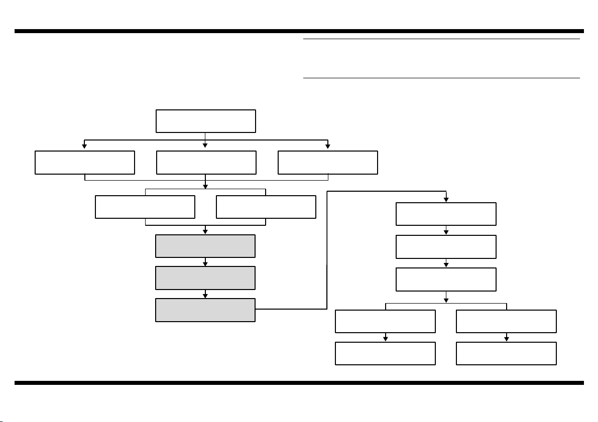
1. Outline of the CF2002/CF3102 System Setup
These Setup Instructions describe the setup for the parts marked in grey in the flowchart
shown below.
When setting up a system consisting of the printer and its various options, perform the
setup according to the procedure described below.
1. Copy Table CT-2
2-A. Paper Feed Unit PF-118
3-A. Dehumidifying Heater
*: U.S.A and Canada only
4: Printer
Unpack the unit, install it, adjust it using the servicing equipment, and
then calibrate the gradation levels with the X-Rite.
5: Control Panel
Attach the control panel to the printer.
6: Printer Controller/Interface Kit
Attach the printer controller, and then specify the necessary settings.
4581-7777-01
2-B. Large Capacity Cabinet
PF-121
3-B. Dehumidifying Heater
4. Printer
5. Control Panel
6. Printer Controller/
Interface kit
NOTE
• Install and setup each option according to the instructions included with the option.
• For information on adjusting the PF-118, PF-121 and AD-14, refer to the section
“Adjusting the Options” on pages 27 to 31 of these Setup Instructions.
2-C. Copy Desk CD-2M
7. Duplex Unit AD-14
8. Data Terminal DT-105*
9. Mechanical Counter
10-A. Finisher FN-8 10-B. Finisher FN-116
11-A. Punch KIT PK-4 11-B. Option tray JS-100
– 1 –
C4581U019AA
Page 3

Printer Panel 1
1.1 Precautions Concerning the Package Contents (Manuals)
The following manuals for the products listed below are included.
NOTE
Manuals that cannot be used with the printer are also included.
■■■■
Printer
• User Manual for a copier*
• Setup Instructions for a copier*
■■■■
Printer Panel 1
• User Manual for a printer (including information on PageScope Light)
• Setup Instructions for a printer (this manual, including information on the printer controller and interface kit)
■■■■
Interface Kit P
• User Manual for a copier (PageScope Light and Scan mode)*
• Installation Guide for a copier (printer controller and interface kit P)*
■■■■
Controller
• Controller User Manual
*:Cannot be used with the CF2002/CF3102 printer.
1.2 Precautions Concerning the Installation of the Controller
When installing the printer controller onto a printer that has the duplex unit attached, the
printer memory must have 512 MB.
4581-7777-01
– 2 –
Page 4
Printer Panel 1
NOTE
2. Unpacking
2.1 Unpacking the Accessories
Remove the accessories from the box, and then check that the following are enclosed.
(1) Imaging units..................................................................................................... 4
(2) Power cord *1 .................................................................................................... 1
(3) LED cleaning tool *2.......................................................................................... 1
(4) LED cleaning paper *2 ...................................................................................... 1
(5) Manual holder ................................................................................................... 1
(6) User Manual...................................................................................................... 1
(7) Setup Instructions ............................................................................................. 1
(8) Warranty card *3 ............................................................................................... 1
(9) Power cord instruction *1 .................................................................................. 1
(10) Paper size label................................................................................................. 1
(11) Cable clamp ...................................................................................................... 1
(12) Cap.................................................................................................................... 1
*1 For Particular area only.
*2 The LED cleaning tool and its paper are not used during setup. Since they will be
needed when the transfer belt unit is changed or the printer is cleaned, keep them
in a safe place for later use.
*3 U.S.A. and Canada only.
2.2 Unpacking the Printer
1. Open the printer box, and then remove the box containing the imaging unit.
2. Open the two handle covers, and then pull out the handles.
4025U018AA
3. Grasp the two handles on the right side of
the printer and the two grips on the left (as
shown in the illustration), and then, while
keeping the printer level, remove it from its
box.
The printer weighs about 85 kg (187-1/4 lbs.).
4025U019AA
The printer must be lifted by at least two people.
4581-7777-01
– 3 –
Page 5
Printer Panel 1
2.3 Removing the Protective Tape and Packing Materials
1. Remove the tape affixed to the outside surface of the printer.
4025U020AA
4025U021AA
Packing
material
Paper take- up
2. Slide out the 1st drawer and remove protective tape and packing materials from the
inside of the drawer.
roller
3. Close the paper drawer.
Ta p e s
Paper take-up
roller
Packing
material
C4004U026AB
4. Slide out the 2nd drawer and remove protective tape and packing materials from the
inside of the drawer.
5. Close the paper drawer.
4581-7777-01
C4004U024AA
– 4 –
Page 6
Printer Panel 1
NOTE
3. Installing the Unit
3.1 Installing the Imaging Unit
1. Open the front door.
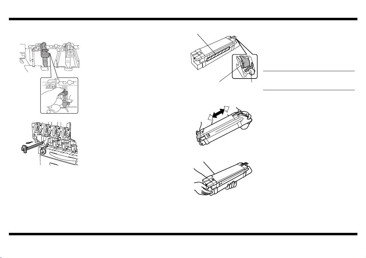
2. Pinch the Imaging Unit release lever for Yel-
C4004U047AA
3. Slide out the protective material.
4025U022AA
low and pull it down forward.
Protective tape
4025U074AC
Interference
preventive sheet
4025U024AA
4025U026AC
4. Take out the Yellow Imaging Unit from the
Imaging Unit carton.
5. Remove the Imaging Unit from its aluminum
package.
6. Remove protective tape and packing material.
Packing
material
Do not peel off the interference preventive
sheet.
7. Tilt the Imaging Unit to the left and, in that
condition, shake it over a small stroke twice.
Then, tilt the Imaging Unit to the right and, in
that condition, shake it over a small stroke
twice.
8. Support the Imaging Unit with both hands
and hold it levelly.
4581-7777-01
– 5 –
Page 7
Printer Panel 1
4025U027AA
4025U028AC
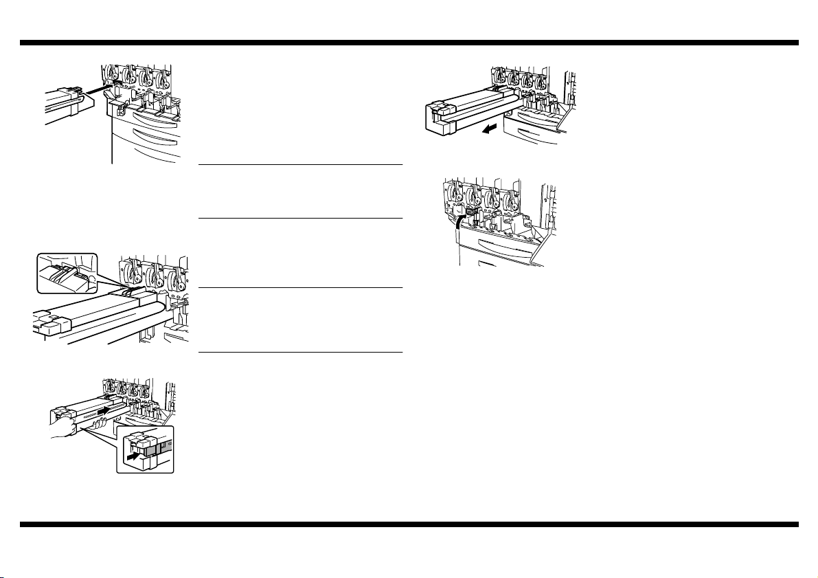
9. Keeping the Imaging Unit in the level position, insert the Imaging Unit into the mounting position on the printer until its leading
edge is stopped.
Make sure that the interference preventive
sheet is left attached to the Imaging Unit
when the Imaging Unit is inserted into the
printer.
NOTE
Make sure the protective sheet is rolled up into
the Imaging Unit, then insert Imaging Unit into
the Printer.
10. Check that the Imaging Unit is inserted positively in position.
NOTE
The positioning rib at the leading edge of the
Imaging Unit cover should be fitted positively
in the hole in the mounting position on the
printer.
11. Supporting the underside of the Imaging
Unit with your left hand, hold the portion of
the unit shown in the illustration with your
right hand and gently push it into position
until a click is heard.
12. Pull out the empty Imaging Unit cover.
4025U030AB
13. Push the Imaging Unit release lever of Yellow all the way until a click is heard.
14. Using the same procedure, install all Imaging Units.
4025U031AA
4025U029AB
4581-7777-01
– 6 –
Page 8
Printer Panel 1
NOTE
3.2 Installing the Toner Cartridge and the Filter
NOTE
Toner does not come with the printer. Purchase toner cartridges (of different colors) separately available.
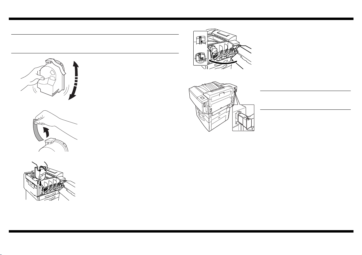
1. Open the front door.
2. Holding the toner cartridge firmly, shake it
well vertically and horizontally to agitate
toner.
C4025O220AB
3. Remove the protective tape.
C4025O221AB
4. Swing the fixing lever downward.
5. Load the toner cartridge in position.
(Make sure that the gear is on the rear side.)
4025U039AA
C4025U001AA
6. Swing the fixing lever upward to fix the toner
cartridges in position.
* Make sure that the fixing lever is positively
swung into position.
7. Using the same procedure, install the toner
cartridges for other colors of toner.
8. Take out the filter and install it in position.
The filter is packed in the box of a black toner
cartridges.
4025U038AA
4581-7777-01
– 7 –
Page 9
Printer Panel 1
NOTE
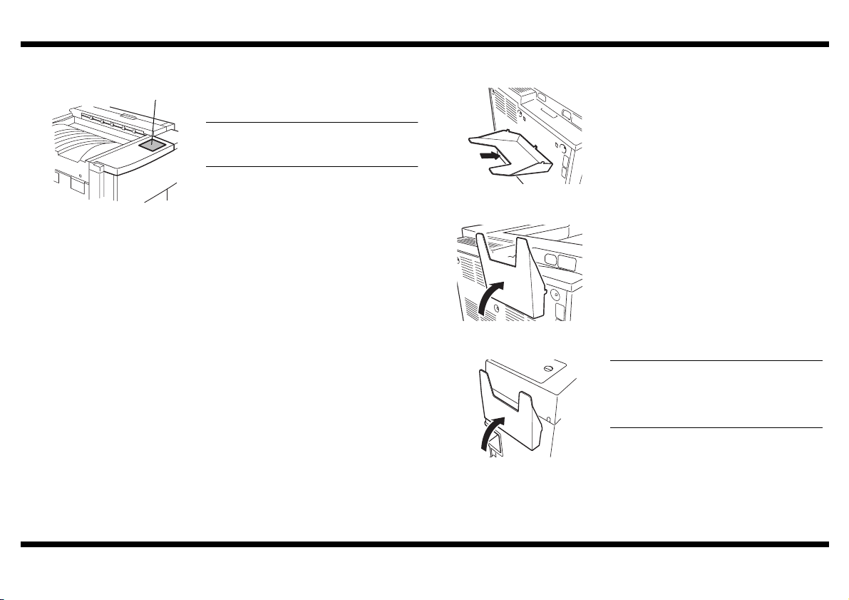
4. Affixing the Label 5. Installing the Manual Holder
Label
C4004U589AA
1. Affix the label on the right side of the top of
the front door.
NOTE
Affix the label that corresponds with the
installed options.
C4004U553AA
C4004U554AA
C4004U098AA
1. Insert the tab on the bottom of the manual
holder into the slot in the printer as shown in
the illustration.
2. Insert the tabs on the left and right sides of
the manual holder into the corresponding
slots in the printer.
If the optional finisher is used, attach the manual holder to the back of the finisher at the
position shown, using the same procedure
described above.
4581-7777-01
– 8 –
Page 10
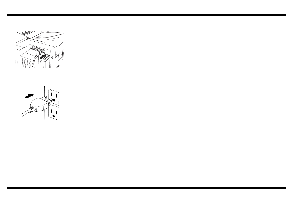
6. Connecting the Cables
C4581U021AA
C4004U139CA
Printer Panel 1
1. Make sure that the printer power cord is not
plugged into the electrical outlet, and then
insert the plug on the end of the power cord
into the power cord connector on the printer.
2. Insert the plug on the other end of the power
cord into an electrical outlet.
4581-7777-01
– 9 –
Page 11
Printer Panel 1
7. Calibrating the Printer
7.1 Loading Test Paper
Load test pattern paper that can be used with X-Rite calibration.
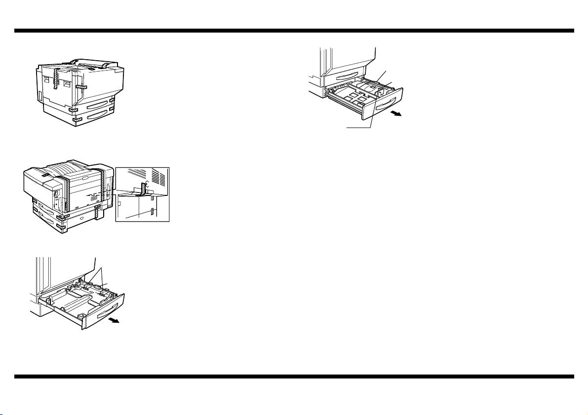
1. Pull out the paper drawer for Tray 1.
2. Load the prepared A4(C)-size (or Letter(C)size) plain paper into the paper drawer.
C4004U074AA
3. Close the paper drawer.
4. Make sure that the media type selection dial
on the drawer is turned to the setting for
plain paper.
5. From the printer panel, select the size of the
test paper loaded into Tray 1.
4025U050AA
NOTE
For details on specifying settings, refer to the
User Manual.
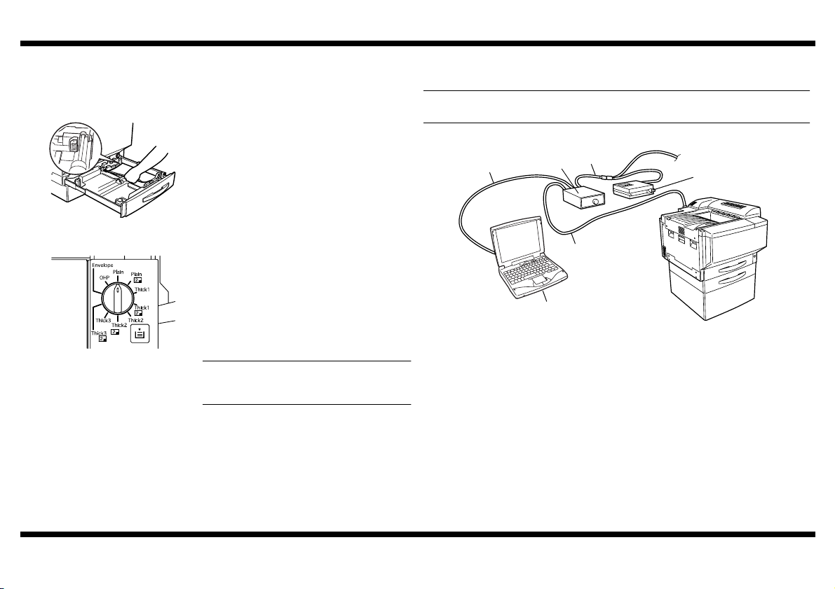
7.2 Setting Up the Servicing Equipment
Set up the equipment in order to print a test pattern and make the necessary adjustments.
NOTE
Do not turn on any equipment until you are instructed to do so.
(4)
(2)
(1) Notebook PC
Starts the External Panel Controller for adjustment.
(2) RS232 straight cable
Connects between the Notebook PC and the connector C of the selector
(3) Selector
Switches between the Notebook PC and the X-Rite, printer
(4) DTP32 cable
Connects between the X-Rite and the connector A of the selector
(5) X-Rite (DTP32)
Color Tone Tester
(6) RS232 straight cable
Connects between the pr inter and the connector B of the selector
(3)
(5)
(6)
(1)
4581-7777-01
– 10 –
Page 12
Printer Panel 1
NOTE
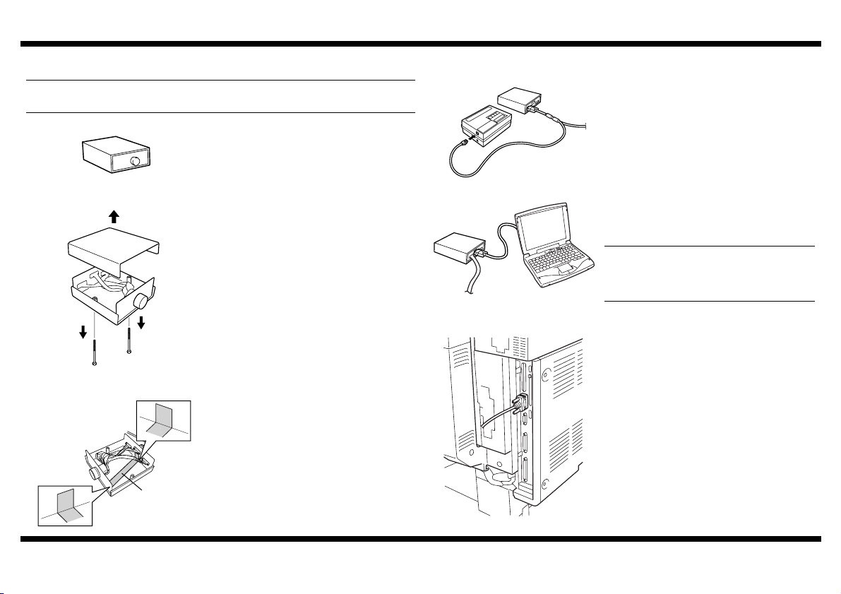
7.3 Setting Up the Selector
NOTE
Prepare aluminum tape before beginning the setup.
1. Remove the selector from its box.
C4004U601AA
2. Remove the two screws from the selector,
and then remove the upper cover.
C4004U602AA
3. Affix aluminum tape to the converter as
shown in the illustration.
7.4 Connecting the Equipment Cables
1. Using a DTP32 cross-cable, connect the I/O
port of the X-Rite to port B of the selector.
C4004U559AA
2. Using the RS232 straight cable (2), connect
the COM 1 port of the computer to port C on
the selector.
When connecting to the COM2 port, set the
External Panel Controller port setting to
C4581U022AA
COM2.
3. Selector and printer connection:
Using a cross-cable, connect port A of the
selector to the printer.
4581-7777-01
Aluminum tape
C4004U603AA
C4581U027AA
– 11 –
Page 13
Printer Panel 1
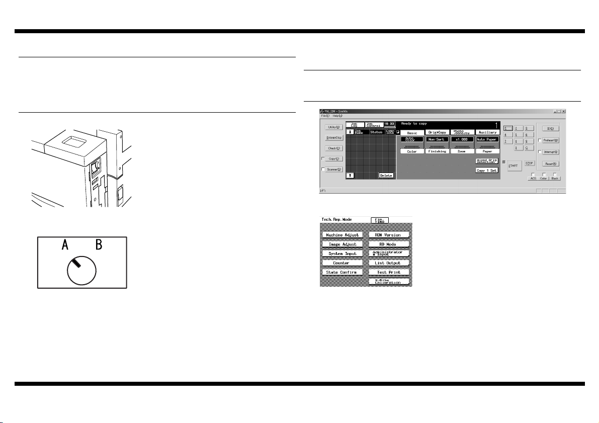
7.5 X-Rite Calibration
NOTE
• Start up the External Panel Controller on the Notebook PC before turning on the
printer.
• If an error message appears, follow the instructions described in the message.
• Do not quit the External Panel Controller while it is being used. If it is quit, restart the
printer and the External Panel Controller.
1. Start up the External Panel Controller on the
Notebook PC.
2. Set the power switch to “I”.
C4004U083AA
3. Make sure that the selector knob is set to
“A”.
C4004U598AA
4. Check that the External Panel Controller appears in the computer screen, and then
display the Tech. Rep. Mode screen. (For details about displaying the Tech. Rep.
Mode screen, refer to the Service Manual.)
NOTE
If the basic screen does not appear in the External Panel Controller, turn the pr inter off.
Restart the External Panel Controller, and then tur n the printer on again.
C4581P003CA
5. Click [X-Rite Calibration] in the Tech. Rep.
Mode screen.
C4581P004CA
4581-7777-01
– 12 –
Page 14
Printer Panel 1
NOTE
C4004P567CA
Test patterns
C4004U568AA
C4004P569CA
C4004P570CA
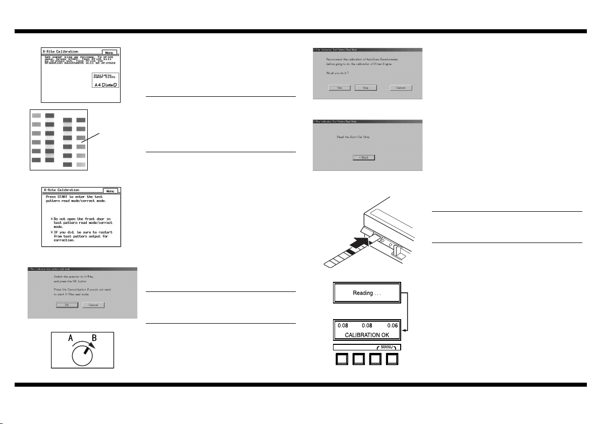
6. Check the message that appears, and then
click the Start key in the External Panel Controller.
Test patterns are printed for the four colors.
(Cyan, Magenta, Yellow, Black)
NOTE
• It will take approximately 2 minutes for the
test patterns to be printed.
• During printing, do not open the front door.
If the front door is opened, restar t the procedure from step 3.
7. After the test patter ns are printed, check that
the message appears, and then click the
Start key in the External Panel Controller.
8. Check that the dialog box appears, and then
click [OK] in the dialog box.
NOTE
If the selector is being used, set the selector
knob to “B”.
C4004P572CA
C4004P573CA
C4004U574AA
9. Check that the dialog box appears, and then
click [Yes] in the dialog box.
10. When the dialog box appears, the auto-cal
strip can be read. Prepare the auto-cal strip.
11. Insert the auto-cal strip into the X-Rite.
Insert the auto-cal strip after “INSERT CAL
STRIP” appears on the X-Rite display.
4581-7777-01
C4004U571AA
C4004U594CA
– 13 –
Page 15
Printer Panel 1
C4004P575CA
3
12. If the reading was completed correctly, the
dialog box shown at the left appears.
Prepare the cyan test pattern.
C4004P578CA
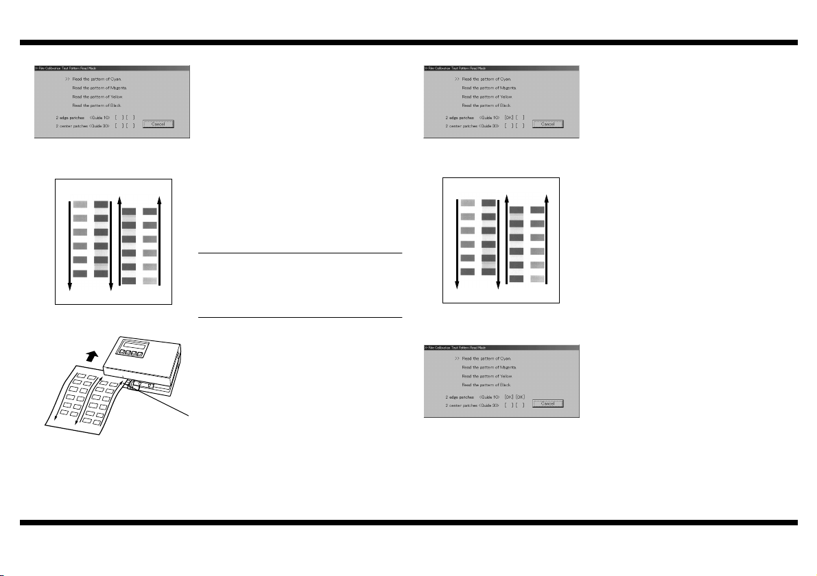
13. Prepare the cyan test pattern, set the X-Rite
1
guide to “10”, and then feed the pattern in
direction “1” to read the row represented by
1
3
14. Check that the dialog box appears.
If the reading was completed correctly, “OK”
is indicated.
15. Turn the test patter n around, and then feed it
to read the row indicated by “B” in direction
“2”.
“A”.
Align the test pattern with the guide, and
insert the pattern into the X-Rite.
NOTE
D
2
4
ABC
C4004U576AA
• The arrows indicate the direction that the
pattern should be fed into the X-Rite.
• The arrows shown in the illustration are not
printed on the actual test pattern.
D
2
4
ABC
C4004U576AA
16. Check that in the dialog box appears.
If the reading was completed correctly, a
second “OK” is indicated.
Guide
C4004P579CA
C4581U025AA
4581-7777-01
– 14 –
Page 16

Printer Panel 1
NOTE
NOTE
1
3
D
2
4
ABC
C4004U576AA
17. Turn the cyan test patter n to its original orientation, set the X-Rite guide to “30”, and
then feed the pattern in direction “3” to read
the row represented by “C”.
1
3
D
2
4
ABC
C4004U576AA
19. Turn the test patter n around, and then feed it
to read the row indicated by “D” in direction
“4”.
20. Check that in the dialog box appears.
If the reading was completed correctly, a
four th “OK” is indicated.
21. Check that “>>” appears beside “Read the
Pattern of Magenta”.
If “>>” appears beside “Read the Pattern of
Cyan”, perform the procedure for reading the
cyan test pattern again.
C4004P580CA
18. Check that in the dialog box appears.
If the reading was completed correctly, a
third “OK” is indicated.
C4004P582CA
22. Prepare the magenta test pattern, and then
repeat steps 13 through 20 of the above procedure to read the magenta test pattern with
the X-Rite.
4581-7777-01
– 15 –
C4004P590CA
If “>>” appears beside “Read the Pattern of
Magenta”, perform the procedure for reading
the magenta test pattern again.
Page 17

Printer Panel 1
NOTE
C4004P591CA
C4004P592CA
23. Prepare the yellow test pattern, and then
repeat steps 13 through 20 of the above procedure to read the yellow test pattern with
the X-Rite.
NOTE
If “>>” appears beside “Read the Pattern of
Yellow”, perform the procedure for reading the
yellow test pattern again.
24. Prepare the black test patter n, and then
repeat steps 13 through 20 of the above procedure to read the black test pattern with the
X-Rite.
NOTE
If “>>” appears beside “Read the Pattern of
Black”, perform the procedure for reading the
black test pattern again.
A
C4004P595CA
B
C4004U593AA
25. Check that the dialog box appears, set the
selector knob on the selector from “B” to “A”,
and then click [OK] in the dialog box.
Be sure to click [OK] only after the selector
knob has been set.
26. Click [Fin. Time].
4581-7777-01
– 16 –
Page 18

Printer Panel 1
8. Making System Setting
8.1 Checking the Date Setting
1. Check that the External Panel Controller appears in the computer screen.
C4581P003CA
2. Click [Utility].
3. Click [User’s Choice: 1].
C4581P005CA
4. Select [1/2].
C4581P007CA
5. Check that the current date and time
settings are correct. If the settings are
not correct, use the keypad in the
External Panel Controller to enter the
correct date and time in the upper row
of the screen.
6. Click [Enter].
7. Click [Exit].
8. Check that the Basic screen appears
on the External Panel Controller.
4581-7777-01
C4581P006CA
– 17 –
Page 19

Printer Panel 1
8.2 Specifying the Serial Number
NOTE
Be sure to specify the serial number.
When the serial number is specified, the settings for each unit can be read by the
printer. If the serial number is not specified, a correctly adjusted image cannot be
printed.
1. Check that the External Panel Controller appears in the computer screen, and then
display the Tech. Rep. Mode screen. (For details about displaying the Tech. Rep.
Mode screen, refer to the Service Manual.)
C4581P003CA
2. Click [System Input].
C4581P004CA
3. Click [Serial # Input].
C4581P008CA
4. Make sure that [Printer] is selected. Using the keypad in the External Panel Controller,
enter the printer’s serial number.
Repeat this step to enter the serial numbers for [LCC], [Sor ter/FN], and [Duplex].
C4581P009CA
5. Click [END].
6. Click [Fin. Time].
7. Check that the Basic screen appears on the External Panel Controller.
4581-7777-01
– 18 –
Page 20

Printer Panel 1
8.3 Specifying Who Performs Replacements
NOTE
The message that appears a unit must be replaced can be changed to indicate that
either the user or the service representative must perform the replacement. Select the
appropriate settings depending on the type of servicing being performed.
1. Check that the External Panel Controller appears in the computer screen, and then
display the Tech. Rep. Mode screen. (For details about displaying the Tech. Rep.
Mode screen, refer to the Service Manual.)
C4581P003CA
2. Click [System Input].
C4581P004CA
3. Click [Unit Change].
C4581P008CA
4. Click [User] or [Service] to select whether each unit should be replaced by the user or
the service representative.
C4581P010CA
5. Click [END].
6. Click [Fin. Time].
7. Check that the Basic screen appears on the External Panel Controller.
4581-7777-01
– 19 –
Page 21

Printer Panel 1
8.4 Printing the List
C4004U087AA
4025U050CA
1. Pull out the paper drawer for Tray 1.
2. Load the prepared A4(L)-size (or Letter(L)size) plain paper into the paper drawer.
3. Close the paper drawer.
4. Make sure that the media type selection dial
on the drawer is turned to the setting for
plain paper.
5. From the printer panel, select the size of the
paper loaded into Tray 1.
NOTE
For details on specifying settings, refer to the
User Manual.
6. Check that the External Panel Controller appears in the computer screen, and then
display the Tech. Rep. Mode screen. (For details about displaying the Tech. Rep.
Mode screen, refer to the Service Manual.)
C4581P003CA
7. Click [List Output].
C4581P004CA
4581-7777-01
– 20 –
Page 22

Printer Panel 1
C4581P019CA
8. Click [Image Processing].
9. Click the [Start] key in the External Panel
Controller. A list of image processing settings and the values of each counter are
printed out.
10. Click [End], and then click [Fin. Time].
11. Check that the message displayed in the
printer panel changes from “Alert Printing
suspended” to “Info”.
12. Exit the External Panel Controller.
8.5 To set the Energy Save Mode parameter
NOTE
When making settings according to the customer’s requests, refer to the procedure
described below.
1. Check that the External Panel Controller appears in the computer screen.
C4581P003CA
2. Click [Utility].
3. Click [User’s Choice:1].
C4581P005CA
4581-7777-01
– 21 –
Page 23

Printer Panel 1
C4581P011CA
C4581P012CA
4. Select [2/2].
5. Click [Energy Saver]
6. Using the keypad in the External Panel
Controller, enter the desired number of
minutes, and then click [Enter].
NOTE
Select the [C] (Clear) key to erase the
entered number.
7. Click [Exit].
8. Click [Exit].
9. Exit the External Panel Controller.
8.6 To set the Sleep Mode parameter
NOTE
When making settings according to the customer’s requests, refer to the procedure
described below.
1. Check that the External Panel Controller appears in the computer screen.
C4581P003CA
2. Click [Utility].
3. Click [User’s Choice:1].
C4581P005CA
4581-7777-01
– 22 –
Page 24

C4581P011CA
Printer Panel 1
4. Select [2/2].
5. Click [Sleep]
6. Using the keypad in the External Panel
Controller, enter the desired number of
minutes, and then click [Enter].
NOTE
Select the [C] (Clear) key to erase the
entered number.
4581-7777-01
C4581P013CA
7. Click [Exit].
8. Click [Exit].
9. Exit the External Panel Controller.
– 23 –
Page 25

Printer Panel 1
NOTE
NOTE
9. Loading Paper
NOTE
For more details about loading paper, refer to the User Manual.
9.1 Tray 1
1. Prepare paper that meets this product’s
specifications.
2. Pull out the paper drawer for Tray 1.
C4004U071AA
3. Press down on the paper-lifting plate until it
locks into place.
C4004U072AA
4. Slide the adjustable paper guides to fit the
size of paper to be loaded.
C4004U074AA
C4004U170AA
5. Load the paper into the drawer so that the
front side of the paper (the side facing up
when the package was unwrapped) faces
up.
• Do not load so much paper that the top of
the stack is higher than the mark indicating
the maximum paper capacity.
• Be careful not to touch the surface of the
paper take-up roller with your hands. If the
roller has been touched, wipe it with a dry
cloth.
6. Slide the adjustable paper guides against
the edges of the paper.
Check that the adjustable paper guides are
pushed up against the edges of the paper.
7. Close the paper drawer.
8. Turn the media type selection dial on the
drawer to the setting for the type of paper
loaded.
4581-7777-01
C4004U073AA
– 24 –
Page 26

Printer Panel 1
NOTE
NOTE
NOTE
9.2 Tray 2
C4004U076AA
C4004U077AA
C4004U078AA
1. Prepare paper that meets this product’s
specifications.
2. Pull out the paper drawer for Tray 2.
3. Press down on the paper-lifting plate until it
locks into place.
4. Slide the adjustable paper guides to fit the
size of paper to be loaded.
C4004U079AA
C4004O108AA
5. Load the paper into the drawer so that the
front side of the paper (the side facing up
when the package was unwrapped) faces
up.
• Do not load so much paper that the top of
the stack is higher than the mark indicating
the maximum paper capacity.
• Be careful not to touch the surface of the
paper take-up roller with your hands. If the
roller has been touched, wipe it with a dry
cloth.
6. Slide the lateral guides against the edges of
the paper.
Check that the lateral guides are pushed up
against the edges of the paper.
7. Close the paper drawer.
8. From the printer panel, select the size of the
paper loaded into Tray 2.
4581-7777-01
For details on specifying settings, refer to the
User Manual.
– 25 –
Page 27

Paper size label
Drawer number label
C4004U141AA
Printer Panel 1
9. Affix the enclosed paper size label to Tray 2
as shown.
10. Affix the enclosed drawer number label as
shown.
4581-7777-01
– 26 –
Page 28

Printer Panel 1
10. Adjusting the Options
NOTE
• With the printer, the adjustments of each option are performed with the servicing
equipment. Therefore, star t up the External Panel Controller, and make the adjustments with the appropriate setting.
• After adjusting the options, restart the printer.
10.1 Checking the Paper Reference Position for PF-118
NOTE
• For details on the installing PF-118, refer to its Setup Instructions.
• To adjust PF-118, follow the instructions below.
1. Load Letter-size (or A4-size) paper into the paper drawer of the optional paper feed
unit.
2. Check that the External Panel Controller appears in the computer screen, and then
display the Tech. Rep. Mode screen. (For details about displaying the Tech. Rep.
Mode screen, refer to the Service Manual.)
C4581P003CA
3. Click “Machine Adjust”.
C4581P004CA
4. Click “PRT Area”.
C4581P014CA
5. Click “Left Margin”.
C4581P015CA
6. Select the key for the paper drawer that is to be adjusted, and then click the Start key
in the External Panel Controller.
A test page is printed.
* If two optional paper feed units are installed, perform the same check and adjustment
procedures in steps 7 and onward also for the fourth drawer.
4581-7777-01
– 27 –
Page 29

Printer Panel 1
a
Paper Exit
Direction
C4658U028AA
7. Measure margin a from the edge of the
paper to the pattern printed in the test page,
and then check that the width of the measured margin meets its standard width.
Standard width of the margin (a):
3.0 mm ± 1.0 mm
If the width of the measured margin does not
meet its standard width, follow the procedure
in the next section, follow the instructions
described below. Position for PF-118, to
adjust it.
8. Select the paper drawer that you wish to
adjust, and then click the up and down
arrows in the lower-right cor ner of the screen
to enter the difference between the measured width and the standard width.
9. Print a test page and check the paper reference position.
If the width of the measure margin does not
meet its standard width, follow the instructions described below.
C4658U024AA
C4658U025AA
10. Open the paper drawer for the cassette that
needs to be adjusted, and then remove all of
the paper.
11. Loosen the two screws on the guide plate at
the bottom of the paper drawer.
12. Adjust the guide plate to the appropriate
position on the scale inside the paper
drawer.
13. Check that the message displayed in the
printer panel changes from “Alert Printing
suspended” to “Info”.
14. Exit the External Panel Controller.
4581-7777-01
– 28 –
Page 30

Printer Panel 1
10.2 Checking and Adjusting the Paper Reference Position for
PF-121
NOTE
• For details on the installing PF-121, refer to its Setup Instructions.
• To adjust PF-121, follow the instructions below.
1. Load Letter-size (or A4-size) paper into the paper drawer of the large-capacity cabi-
net.
2. Check that the External Panel Controller appears in the computer screen, and then
display the Tech. Rep. Mode screen. (For details about displaying the Tech. Rep.
Mode screen, refer to the Service Manual.)
C4581P003CA
3. Click “Machine Adjust”.
4. Click “PRT Area”.
C4581P014CA
5. Click “Left Margin”.
C4581P015CA
6. Select the key for the third paper drawer, and then click the Start key in the External
Panel Controller.
7. Measure the margin from the edge of the
paper to the pattern printed in the top-right
a
Paper Exit
Direction
corner of the test page.
Standard width (a):
3.0 mm ± 1.0 mm
Click the up and down arrows in the lowerright corner of the screen to enter the difference (in millimeters) between the measured
width and the standard width.
4581-7777-01
C4581P004CA
– 29 –
C4658U028AA
8. Print another test page and check the paper
reference position.
Page 31

Printer Panel 1
10.3 Checking and Adjusting the Paper Reference Position for
AD-14
NOTE
• Perform the procedure below after adjusting the paper reference positions for the
paper feed unit and the large-capacity cabinet.
• For details on the installing AD-14, refer to its Setup Instructions.
• To adjust AD-14, follow the instructions below.
1. Load Letter size (or A4-size) paper into the paper drawer of the all Trays.
2. Check that the External Panel Controller appears in the computer screen, and then
display the Tech. Rep. Mode screen. (For details about displaying the Tech. Rep.
Mode screen, refer to the Service Manual.)
C4581P003CA
3. Click “Machine Adjust”.
4. Click “PRT Area”.
C4581P014CA
5. Click “Dup. Left Margin”.
C4581P016CA
6. Click “1st.”.
7. Click the Start key in the External Panel Controller.
A test page is printed.
4581-7777-01
C4581P004CA
– 30 –
Page 32

Printer Panel 1
8. Measure the width of loss for the test pattern
printed on the back of the test page.
Paper Exit
Direction
A
4657U006AA
NOTE
Do not measure from the back of the test pattern.
Standard width (a):
3.0 mm ± 1.0 mm
If the measured width of loss does not meet
its standard width, click and in the
lower-right corner of the screen to adjust the
width. Print another test page and check the
printed image.
9. Adjust the paper reference positions for the
2nd, 3rd and 4th drawers in the same way
(by repeating steps 6 through 8).
NOTE
The 4th drawer is only available if two optional
paper feed units are installed.
4581-7777-01
– 31 –
Page 33

Printer Panel 1
11. Preparing for Installation of the Controller
Before installing the controller, make the following settings.
■■■■
Selecting the “Printer” Setting
Use the External Panel Controller to change the “Priority Device” setting to “Printer”.
[Default setting: Copier]
1. Press the [Utility] key on the External Panel Controller.
2. Click [1/2] on the User’ Choice: 2 screen.
3. Click [Printer] for the “Priority Device” setting.
■■■■
Specifying the Administrator Access Code
Use the “Tech. Rep. Mode” of the External Panel Controller to specify the administrator
access code, and then inform the customer of the specified access code.
NOTE
The access code is required in order to log into the Administrator mode of PageScope
Light.
[Default setting: 0000]
■■■■
Specifying the Peripheral Setting
Change the Peripheral setting for the External Panel Controller to “Controller 2”.
[Default setting: Without Controller]
1. Enter the Tech. Rep. Mode of the External Panel Controller.
2. Click [Peripheral Setting] of the System Input.
3. Click [Controller 2].
4. Set the power switch of the printer to “O”.
5. Remove the servicing equipment.
4581-7777-01
C4581P017CA
– 32 –
Page 34

Printer Panel 1
12. Installing the Printer Panel
12.1 Checking the Contents of the Printer Panel
Before starting to set up, check that the following accessories are included with this unit.
(1) Printer panel...................................................................................................... 1
(2) Circuit board mounting screws.......................................................................... 3
(3) User Manual...................................................................................................... 1
(4) Setup Instructions (this manual)........................................................................ 1
(5) Label ................................................................................................................. 1
(1) (2)
(5)
(3)
(4)
C4581U017AA
12.2 Install the Printer Panel for the Internal Controller
1. Open the front door.
C4581U001AA
2. Remove the screw and the cover shown in
the illustration.
C4581U002AA
3. Remove the two screws and the cover
shown in the illustration.
C4581U003AA
4581-7777-01
– 33 –
Page 35

Printer Panel 1
C4004U239AA
C4581U004AA
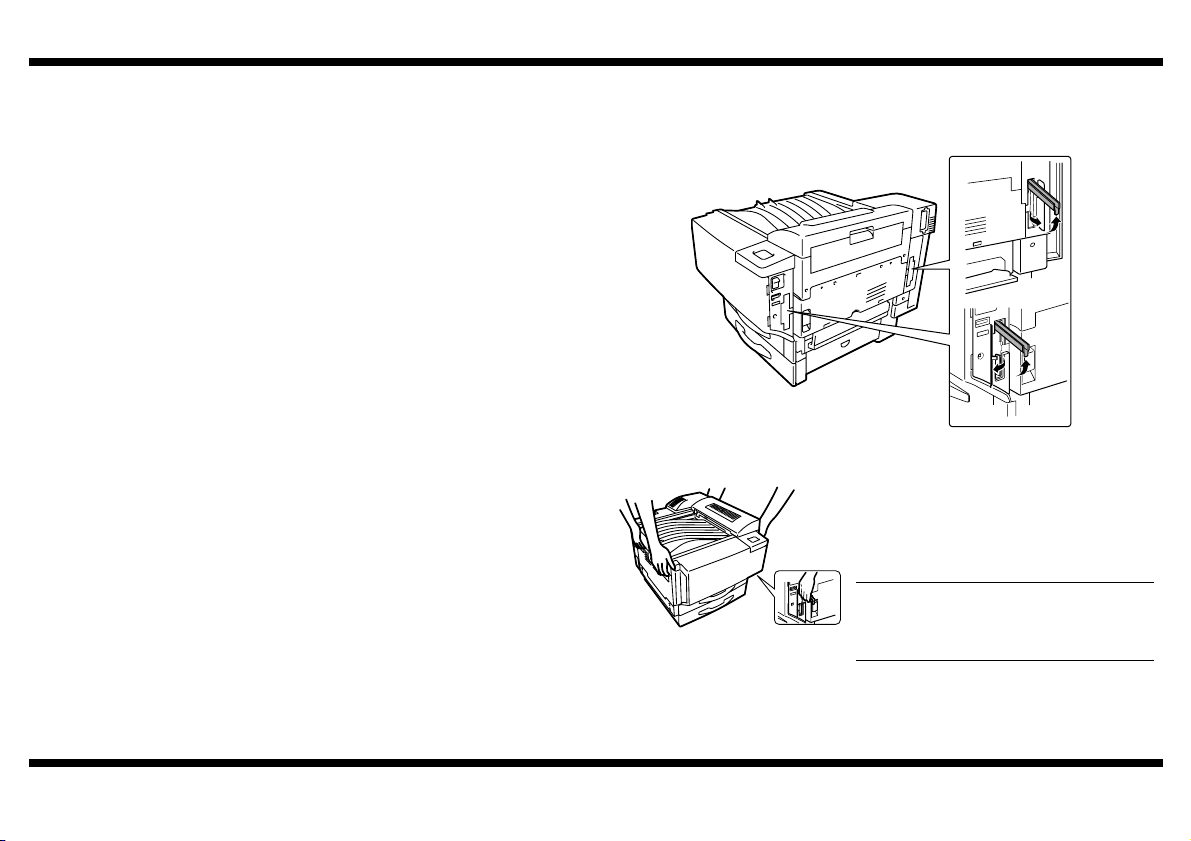
4. Pull out the controller connector.
5. Remove the connector cover shown in the
illustration.
6. Pass the controller connector pulled out in
step 5 through the hole as shown.
NOTE
Be careful not to disconnect other connectors
accidentally.
C4581U006AA
C4581U007AA
7. Install the cover as shown in the illustration.
8. Insert the connector mentioned in step 6 into
the connector on the back of the printer
panel for the internal controller.
9. Install the printer panel for the internal controller in place of the cover removed in
step 2.
4581-7777-01
C4581U005AA
C4581U008AA
– 34 –
Page 36

C4581U009AA
C4581U010AA
Printer Panel 1
10. Secure the printer panel for the internal controller with the screw used to secure the
cover.
11. Close the front door.
4581-7777-01
– 35 –
Page 37

Printer Panel 1
13. Installing the Printer Controller
13.1 Operating Environment
The printer controller operates under the following environment.
PCL driver (only for the Windows operating system) and PS driver are available.
Computer IBM-compatible PC, Mac OS or PowerPC
Operating System
and Memory
Direct Connection IEEE1284 (Compatible/Nibble/ECP)
Network Environment
Software Microsoft Internet Explorer
NOTE
When installing the printer controller onto a printer that has the duplex unit attached, the
printer memor y must have 512 MB.
Processor: i486DX or higher
Hard disk free space: 10 MB or more
Windows 98, Me and NT 4.0 (SP6 or later): 16 MB or more
Windows 2000 (SP2 or later) or XP: 128 MB or more
Mac OS 8.5 or later: 32 MB or more
Standard Ethernet 10/100BaseT
Protocol TCP/IP, AppleTalk,
IPX/SPX (NetWare 4.x/5.x)
Ver. 5.5 or later (Windows OS)
Ver. 5.0 or later (Mac OS)
Netscape Communicator
Ver. 4.5 or later
13.2 Outline of Setup
Set up the printer controller according to the procedures shown below.
Check the contents of the enclosed
Specifying the printer controller settings.
interface kit.
↓
Install the controller.
↓
Checking with a test print.
To turn off the printer controller.
↓
↓
Connect the cables.
↓
Install the patch files.
↓
Finish
p. 37
p. 37
p. 41
p. 42
p. 42
p. 43
p. 44
4581-7777-01
– 36 –
Page 38

Printer Panel 1
-
-
e
e
13.3 Checking the Contents of the Enclosed Interface Kit
Before starting to set up, check that the following accessories are included with this unit.
1. Controller mounting plate ........................................................................................ 1
2. Controller cover ....................................................................................................... 1
3. Power cord cover ..................................................................................................... 1
4. Fan assembly .......................................................................................................... 1
5. Shoulder screws ...................................................................................................... 3
6. Screws (6 for installing the circuit board and 3 for installing the fan) ....................... 9
7. Screws
(5 for temporary mounting, 11 for installing the controller cover and
2 for installing the controller) ................................................................................. 18
8. Screws (for installing the power cord cover) ............................................................ 2
9. CKN clamp .............................................................................................................. 2
10. Installation Guide* ................................................................................................... 1
11. CD-ROM* ................................................................................................................ 1
*:Cannot be used with the CF2002/CF3102 printer.
9
C4025U909AA
Cd_1
10
11
C4025U901AA
C4025U902AA
C4025U903AA
1
C4025U904AA
2
3
C4025U905AA
C4025U906AA
C4025U908AA
C4025U907AA
4
5
6
7
8
13.4 Installing the Interface Kit and Printer Controller Circuit
Board
NOTE
A Phillips screwdriver is needed in order to install the printer controller circuit board.
1. Attach the controller circuit board to the con
troller mounting plate using the three shoul
➁
➀
➂
C4025u912AA
C4025u910AA
der screws (5) by tightening them in th
following order: ➀, ➁, then ➂.
2. Secure the controller circuit board with th
six screws (6) for installing the circuit board.
4581-7777-01
– 37 –
Page 39

Printer Panel 1
s
r
t
e
y
C4342u001BA
C4025u911AA
C4025u913AA
3. Secure the IEEE1284 connector to the controller mounting plate using the two screw
enclosed with the controller circuit board.
4. Connect the three connectors.
5. Install the fan assembly on top of the shoulder screws, and then secure it using the
three screws (6) for installing the fan.
6. Connect the fan connector to the controlle
circuit board.
C4025u914AA
➁
7. Install the controller cover, and then secure i
using the 16 screws (7) for installing th
cover.
Tighten the screw indicated by ➀ first, and
then tighten the screw indicated by ➁. The
remaining screws can be tightened in an
order.
➀
C4025u916AA
4581-7777-01
– 38 –
Page 40

Printer Panel 1
s
e
e
8. Hook the two tabs at the back of the interface kit into the notches on the back of the
printer.
C4025u917AA
9. Secure the interface kit with the two screw
(7) for installing the controller.
11. Install the power cord cover, and then secur
it using the 2 screws (8) for installing th
power cord cover.
C4025u920AA
12. Connect the printer cable to the printer.
4581-7777-01
C4025u918AA
C4025u919AA
10. Connect the controller power cord to the
printer.
C4025u921AA
– 39 –
Page 41

Printer Panel 1
13. Attach a CKN clamp at the lower-left corner of the back of the printer, and then pass
the printer cable though the clamp. Attach a CKN clamp to the right side of the interface kit, and then pass the power cord through the clamp.
Printer cable guide Power cord guide
4581-7777-01
C4581U013AA
C4581U026AA
– 40 –
Page 42

Printer Panel 1
14. Specifying the Printer Controller Settings
From the printer, specify the necessary settings for using the controller.
1. Turn on the printer.
C4581O014AA
2. Turn on the printer controller.
C4581O015AA
3. After several minutes, a printer panel for selecting the language appears. Select the
desired language.
5. Display the Setup Mode screen in the printer
panel, press ▲ or ▼ until “Server Setup”
appears, and then press the [Set] key.
6. Press the [Menu] key in the printer panel.
When “Save Changes” appears, select
“Ye s ”, and then press the [Set] key.
7. In the same way, select “Network Setup”,
and then press the [Set] key. Select “Proto-
C4581U031AA
8. Specify settings for the following.
IP address : Controller IP address
Subnet Mask : Subnet mask for the connected network
Default Gateway : IP address of the default gateway
NOTE
First, check with your network administrator for the settings that should be entered.
9. After selecting the necessary settings, select “Exit TCP/IP Setup”, “Exit Protocol
Setup”, then “Exit Network Setup”. Display “Save Changes”, and then press the [Set]
key.
10. Press ▲ or ▼ until “Printer Setup” appears, and then press the [Set] key.
11. Press the [Menu] key in the printer panel. When “Save Changes” appears, select
“Ye s ”, and then press the [Set] key.
12. When “Exit Setup” appears, press the [Set] key to restart the printer controller.
col Setup”, “TCP/IP Setup”, then “Ethernet
Setup”, and then set “TCP/IP-Ethernet” to
“Ye s ” and “Enable AutoIP Config” to “No”.
4. Select the appropriate Market Region setting.
4581-7777-01
– 41 –
Page 43

Printer Panel 1
15. Checking With a Test Print
After setting up the controller, print the Configuration page to check that the controller is
operating correctly.
1. Press the [Menu] key on the printer panel.
2. Touch the selection button corresponding to
[Print Pages].
The names of the pages that can be printed
are displayed.
3. Touch the selection button corresponding to
[Configuration].
C4004O596CA
16. Connecting the Cables
Use the IEEE1284 (Centronics), or network cable (Category 5 or 5E).
■■■■
LED descriptions
Para lle l port
10BaseT/100BaseT
Ethernet connector
for a twisted-pair cable
10/100 BaseT indicator
Off: 10BaseT
On: 100BaseTX
Fiery power indicator
Network connector indicator
Off: Network interrupted
Flashing: Network running
Fiery HDD indicator
C4581U029CA
4581-7777-01
– 42 –
Page 44

Printer Panel 1
17. Installing the Patch Files
■■■■
Objective
The controller is recognized as Minolta printer in a network management tool
(EX. PageScope Net Care) at the time of use. In addition, the Minolta logo appears at the
top of the PageScope Light page.
NOTE
This patch file is not provided on the CD-ROM supplied with the controller ; it must be
acquired separately.
■■■■
Patch file installation procedure
1. Check that the computer can communicate with the controller through TCP/IP.
2. Install the Command Work Station Utility from the CD-ROM included with the controller on the computer.
NOTE
This software can only be used with the Windows operating system.
3. Start up the Command Work Station.
4. Select the controller from Available Servers, and then click [Add].
5. Login with administrator authorization.
6. Select the Job from Import in the File Menu.
7. In the Select File to Import dialog, select the patch file, select [31 C-M] in the Logical
Printer, and then click [Import].
8. In order to apply the patch file settings, the controller must be rebooted.
After waiting 60 seconds or more, restart the controller.
9. When PageScope Light is accessed, check that the Minolta logo appears on the page,
as shown below.
To access PageScope Light:
Enter the IP address of your controller into the Address box of the Web browser.
(Example) http://IP address of the controller/
The PageScope Light page appears as shown below before the patch file is installed.
Before installing the patch file
C4581P018CA
After installing the patch file
4581-7777-01
C4581P101CA
– 43 –
Page 45

Printer Panel 1
”
-
”
r
18. To turn off the printer controller
NOTE
If the printer controller is turned off in a manner other than described in “To turn off the
printer controller”, the controller may be damaged.
1. Check that “Info XXXX” appears in the display, and then press the [Menu] key in the
printer panel.
C4004O583CA
2. Press ▲ or ▼ until “Functions Shut Down
appears, and then press the [Set] key.
C4004O586CA
C4004O587CA
C4004O588CA
3. Press ▼ on ▲ to display “Shut Down Sys
tem”, and then press the [Set] key to begin
shutting down the system.
4. When the system has finished shutting
down, “Safe to power off the system
appears.
5. Set the power switch of the printer controlle
to “2” to turn off the printer controller.
4581-7777-01
– 44 –
Page 46

Printer Panel 1
r
NOTE
19. Setting the User Environment (Administrator Operations volume)
The following procedures are basically for administrators. Refer to the following only if a
request for setup is received from the user.
NOTE
The network and computer environment for the user is usually controlled by a specialized administrator. Before performing the setup procedure described below, first obtain
approval from the administrator, and then perform the operations under the administrators supervision.
19.1 Specifying User’s Choice Settings
Set up the printer controller according to the procedures shown below.
Specify the print settings.
Local→Specify the settings necessary for a local
connection.
Network→Specify the settings necessary for a
network connection.
↓
Check the operation.
↓
Finish
Troubleshooting
p. 45
p. 50
p. 50
19.2 Entering Setup Mode on the Controller
In order to select functions, the “Functions” menu must be selected.
1. Check that “Info xxxx” appears in the display,
and then press the [Menu] key in the printe
panel.
“xxxx” indicates the “Server Name”.
C4004O583CA
2. Press ▲ or ▼ until “Run Setup” appears, and
then press the [Set] key.
C4581U030AA
4581-7777-01
– 45 –
Page 47

Printer Panel 1
t
C4581U015AA
3. When “Continue to Setup?” appears, selec
“Ye s ”, and then press the [Set] key.
19.3 Common Settings for Controllers
(The recommended settings are underlined and the settings within [ ] are the default settings.)
Server Setup Server Name Enter the server name.
Printer Setup Publish Direct Yes
Publish Print Queue Yes
Publish Hold Queue Yes
/No [Yes]
/No [Yes]
/No [Yes]
19.4 Settings Required for a Local Connection
(IEEE1284 (Centronics))
Controller settings
(The recommended settings are underlined and the settings within [ ] are the default settings.)
Network Setup Port Setup >
Parallel Port Setup
PC Settings
1. Start up the Add Printer Wizard, and then click [Next].
2. In the dialog where the printer connection can be selected, select [Local printer], and
then click [Next].
3. In the dialog where the manufacturer and model of the printer can be selected, click
[Have Disk].
4. Click [Browse], select the setting file from the corresponding folder on the CD-ROM,
and then click [OK].
5. Select the model of the printer from the printer list, and then click [Next].
6. Select the LPT1 por t, and then click [Next].
7. When [Next] is clicked, installation of the driver will begin.
8. Specify the printer name and whether the printer will be the default printer and
whether a test print will be printed.
Enable Parallel Port Yes
Port Timeout 5-60 [5]
Ignore EOF Yes
/No [No]
/No [Yes]
4581-7777-01
– 46 –
Page 48

Printer Panel 1
19.5 Specifying the Settings Necessary for Printing on a Network
The following procedure describes how to specify the settings necessary for printing on a
network.
Follow the procedure described below to specify the settings necessary for printing on a
network.
1. Refer to [Settings Required for a Local Connection] and install the printer driver. At this
time, specify the LPT1 port as the printer port.
NOTE
Do not print a test page yet.
Perform the test print after the network connection settings have been specified.
2. Follow the procedure below to specify the settings necessary for printing on a net-
work. Change the printer port from the one specified when the printer driver was
installed in step 1 to a port for a network connection, and then change any controller
settings as necessary.
NOTE
For IPP printing and NetWare printing, begin from the time when the printer driver was
added.
■■■■
Network Printing on a Computer Running Windows
Procedure for connecting a network that can be selected for the various Windows operating systems
The procedure for specifying settings differs depending on the output procedure (LPR,
Windows printing or IPP).
Follow the appropriate connection procedure for the environment that you are using.
Windows
98/Me
LPR
SMB
IPP
Windows NT
4.0
2222
Windows
2000
222
Windows XP Protocol
Used
22
TCP/IP
■■■■
SMB printing
Controller settings
(The recommended settings are underlined and the settings within [ ] are the default settings.)
Network Setup Protocol Setup >
PC Settings
• From the window displayed by clicking the Start button, pointing to [Settings], then
clicking [Printers], select the printer. Then, from the menu that appears by right-clicking the printer, click [Properties].
For Windows 98 and Me:
1. Click the Details tab, and then click [Add Port...].
2. Select [Network], and then click [Browse...].
3. From the console tree showing the network configuration, select the printer with the
server name registered in the controller.
4. Click [Close] to close the dialog.
For Windows NT 4.0, 2000 and XP:
1. Click the Ports tab, click [Add Port], double-click [Local Port], and then type in
[\\server_name\print].
2. Click [Close] to close the dialog.
TCP/IP Setup >
Ethernet Setup
Service Setup >
Windows Setup
TCP/IP-Ethernet Yes/No [Yes]
Enable AutoIP Config Yes/No
IP Address Enter the IP
Subnet Mask Enter the subnet
Gateway Address Enter the IP
Enable Windows Printing Yes
Choose Domain Select from list/
[Yes]
address.
mask.
address of the
gateway.
/No [Yes]
Enter manually
[Select from list]
4581-7777-01
– 47 –
Page 49

Printer Panel 1
■■■■ LPD (LPR) printing
Controller settings
(The recommended settings are underlined and the settings within [ ] are the default settings.)
Network Setup Protocol Setup >
PC Settings
For Windows NT 4.0:
1. Install the Microsoft TCP/IP Printing service.
• Open Control Panel, and then double-click the Network icon.
• In the Network dialog, click the Ser vices tab, and then click [Add...].
• Select [Microsoft TCP/IP Printing], and then click [OK].
2. Display the printer properties.
3. Click the Ports tab, and then click [Add Port...]. The Printer Ports dialog appears.
4. From the Available Printer Ports, select [LPR Port], and then click [New Ports].
5. In the Add LPR Compatible Printer dialog, type the IP address of the controller into the
Name or address of server providing lpd field.
6. Type [print] or [hold] into the Name of printer or print queue on that server field.
7. Specify the printer name and whether the printer will be the default printer and
whether a test print will be printed.
8. Click [Close] to close the dialog.
For Windows 2000 and XP:
1. Display the printer properties.
2. Click the Ports tab, and then click [Add Port...]. The Printer Ports dialog appears.
3. From the Available port types list, select [Standard TCP/IP Port], and then click [New
Port...].
4581-7777-01
TCP/IP Setup >
Ethernet Setup
Service Setup >
LPD Setup
TCP/IP-Ethernet Yes
Enable AutoIP Config Yes/No
IP Address Enter the IP
Subnet Mask Enter the subnet
Gateway Address Enter the IP
Enable LPD Yes
/No [Yes]
[Yes]
address.
mask.
address of the
gateway.
/No [Yes]
4. Type the IP address of the controller into the field.
5. Select [Custom], and then click [Setting].
6. Select [LPR].
7. Type [print] or [hold] into the field, and then click [OK].
8. Click [Next], then [Finish] to close the dialog.
■■■■ IPP printing
Controller settings
(The recommended settings are underlined and the settings within [ ] are the default settings.)
Network Setup Service Setup >
PC Settings
1. Start up the Add Printer Wizard, and then select [Network Pr inter].
2. In the Locate Your Printer dialog, select [Connect to a printer on the Internet or on your
intranet].
3. Type [http://printer_IP_address/ipp/print] into the URL field.
4. In the dialog where the manufacturer and model of the printer can be selected, click
[Have Disk].
5. Click [Browse], select the corresponding folder on the CD-ROM, and then click [OK].
6. Select the model of the printer from the printer list, and then click [Next].
7. Click [Finish] to exit the Add Printer Wizard.
8. Specify the printer name and whether the printer will be the default printer and
whether a test print will be printed.
IPP Setup
Enable IPP Yes/No [Yes]
– 48 –
Page 50

Printer Panel 1
■■■■ Network Printing on a Macintosh Computer
AppleTalk printing
Controller settings
(The recommended settings are underlined and the settings within [ ] are the default settings.)
Network Setup Protocol Setup >
Settings for a Macintosh computer
1. Double-click the AdobePS Installer icon.
2. After installation is finished, restart the computer.
3. Select Chooser from the Apple menu.
4. Click the AdobePS icon. (Make sure that AppleTalk is set to [Active].)
5. If zones are listed, select the correct AppleTalk zone.
6. From the Select a PostScript Printer list, select the type of connection used by the
controller, and then click [Create].
7. Select the PPD file for the model of the printer that was installed, and then click [OK].
8. Close the Chooser.
AppleTalk Setup
Enable AppleTalk Yes
AppleTalk Zone Select the zone
/No [Yes]
from the list.
■■■■ NetWare environment
Settings for NetWare printing
The controller supports the following NetWare environments.
NetWare Version Service Settings That Must Be Specified
Netware 4.X PServer NDS, Pserver name, NDS context/
Netware 5.X PServer/NDPSPrinter NDS, Pserver name, NDS context/
From the Controller Operation
Screen
Tr e e
Tree (Only LPR printing with TCP/IP
is supported in NDPS.
Specify the TCP/IP settings.)
Controller settings
(Select the necessary settings according to the user’s environment.)
Network
Setup
PC Settings
1. Start up the Add Printer Wizard, and then select [Network Pr inter].
2. Display the printer on the network (click [Browse] for Windows 98 and Me, or click
[Next] for Windows 2000 and XP), and then select the queue name (name of NDPS
Printer Agent for NDPS) for the printer registered with the server.
3. In the dialog where the manufacturer and model of the printer can be selected, click
[Have Disk].
4. Click [Browse], select the corresponding folder on the CD-ROM, and then click [OK].
5. Select the model of the printer from the printer list, and then click [Next].
6. Follow the instructions of the Add Printer Wizard to finish installing the dr iver.
Protocol Setup > IPX/SPX Setup IPX Auto Frame
Service Setup >
PServer Setup
Enable Pserver No
NDS Setup Enable NDS No
Bindery Setup Add File Server,
NetWare Server Poll Interval (sec) 1-3600 [15]
Ty p e
Frame Setup Ethernet 802.2
Select NDS
Navigate to the
Print Server
Navigate to the
Print Server
Ye s
Ethernet 802.3
Ethernet II
Ethernet SNAP
Select the tree.
Select the printer
server.
Select the tree.
Select the printer
server.
4581-7777-01
– 49 –
Page 51

Printer Panel 1
20. Checking Operation After Specifying Settings
After the setup procedures for the controller and user environment are finished, check the
operation to ensure that the setup has been performed correctly.
Performing a test print from client PC
This operation is performed to check if the settings for the connection with the computer
are correct.
1. In the windows displayed by clicking the Star t button, pointing to [Settings], then clicking [Printers], right-click the printer, and then click [Properties].
2. Click the General tab, and then click [Print Test Page].
If the test page cannot be printed, refer to [Installation Troubleshooting].
21. Installation Troubleshooting
When printing cannot be carried out over a network:
Check Possible Cause Action
1 Does the print job
appear in the touch
panel of the copier?
2 Is there a response
from pinging sent
from the computer
to the controller?
Yes A printer error (out of
paper, out of toner, etc.)
occurred.
No The data has not yet
been received.
Yes The print destination por t
setting is incorrect.
The computer is temporarily malfunctioning.
The printer driver is not
installed correctly.
No The controller circuit
board is temporarily malfunctioning.
The network cable is disconnected or the relay
device is faulty.
The IP address and/or
subnet mask is incorrectly specified.
Correct the cause of the
error.
Go to 2.
Specify the correct por t.
Restart the computer.
Follow the procedure to
correctly uninstall, then
re-install the printer
driver.
Restart the controller.
Correctly connect the
cable, or restart or
replace the relay device.
Specify the correct IP
address and subnet
mask.
4581-7777-01
– 50 –
 Loading...