

Page 1
User Manual
[
Administrator Operations
CF2002/CF3102
]
1
Read First
Introduction
Safety Information
Precautions
Part Names and Their Functions
Utility Mode Operations
Touch Panel Messages
Troubleshooting
Appendix
Page 2

Contents
Contents
The topics listed below are described in the “Administrator Operations” volume.
For details on other topics, refer to the Basic Operations and the Advanced Operations volumes of the User Manual and the Enlarge Display Mode Operation Guide.
1 Introduction
1.1 Introduction...................................................................................1-2
Structure of the Manual...................................................................1-2
1.2 Explanation of Manual Conventions ...........................................1-3
1.3 Explanation of Basic Concepts and Symbols............................1-4
Paper Feeding.................................................................................1-4
“Width” and “Length”.......................................................................1-5
Paper Orientation............................................................................1-5
Portrait and Landscape...................................................................1-5
Display Icons...................................................................................1-6
Paper Supply Icons.........................................................................1-6
®
1.4 Energy Star
What is an ENERGY STAR® Product?...........................................1-7
1.5 Trademarks and Registered Trademarks ...................................1-7
..................................................................................1-7
2 Safety Information
2.1 Warning and Precaution Symbols...............................................2-2
2.2 Meaning of Symbols .....................................................................2-2
WARNING.......................................................................................2-3
CAUTION........................................................................................2-4
2.3 Precautions for Routine Use........................................................2-5
2.4 USER INSTRUCTIONS .................................................................2-5
FCC PART 15 - RADIO FREQUENCY DEVICES
(For U.S.A. Users)...........................................................................2-5
2.5 INTERFERENCE-CAUSING EQUIPMENT STANDARD ..............2-6
(ICES-003 IS-SUE 3) (For Canada Users) .....................................2-6
2.6 For Users in countries not subject to Class B regulations.......2-6
2.7 LED Radiation Safety....................................................................2-6
2.8 Ozone Release...............................................................................2-6
CF2002/CF3102 i
Page 3

3 Precautions
3.1 Installation Precautions ............................................................... 3-2
Installation Site ............................................................................... 3-2
Power Source................................................................................. 3-2
Space Requirements...................................................................... 3-3
3.2 Operation Precautions ................................................................. 3-4
Operating environment................................................................... 3-4
Proper use ...................................................................................... 3-4
Transporting the copier................................................................... 3-5
Care of copier supplies................................................................... 3-5
Storage of copies............................................................................ 3-6
3.3 Legal Restrictions on Copying.................................................... 3-7
4 Part Names and Their Functions
4.1 Components and Their Functions .............................................. 4-2
4.2 Parts Names and Their Functions .............................................. 4-5
Outside of Copier............................................................................ 4-5
Supplies and Parts ......................................................................... 4-8
Inside of Copier .............................................................................. 4-9
Options ......................................................................................... 4-10
Contents
5 Utility Mode Operations
5.1 Utility Screen................................................................................. 5-2
Specifying the Input Screen Functions........................................... 5-3
Specifying the Initial Mode Settings (“Reset Mode” Function)........ 5-4
To specify the initial mode settings................................................. 5-4
Using Copy Programs .................................................................... 5-5
To store a copy program ................................................................ 5-5
To recall a stored copy program and use it to make copies........... 5-6
5.2 Specifying Default Settings (“User’s Choice” Functions)........ 5-7
User’s Choice: 1 Screens............................................................... 5-7
User’s Choice: 2 Screens............................................................... 5-9
To set the “Confirmation Beep” function....................................... 5-10
To set the “Date/Time Set” function.............................................. 5-11
To set the “Memory Recall” function............................................. 5-13
To set the “Key Repeat Start Time/Interval” function ................... 5-15
To set the “Auto Panel Reset” function......................................... 5-16
To set the “Energy Saver” function............................................... 5-17
To set the “Sleep” function ........................................................... 5-18
To set the “Auto Clear Mode” function.......................................... 5-19
To set the “Enlarge-Display Notice” function ................................ 5-20
“Specialty Paper” Settings ............................................................ 5-21
ii CF2002/CF3102
Page 4

Contents
To set the “Specialty Paper” function............................................5-22
Specifying the Output Tray Priority ...............................................5-23
To set the “Priority exit tray” function ............................................5-23
To set the “Intelligent Sorting” function .........................................5-24
To set the “Criss Cross Mode” function.........................................5-25
To set the “Priority Device” function ..............................................5-26
To set the “ACS Judgement Level Adjust.” function .....................5-27
To set the “2in1, 4in1, Booklet Copy Zoom” function....................5-28
To set the “Auto-select Paper for Small Original” function............5-29
To set the “4in1 Copy Order” function...........................................5-30
To set the “Centering” function......................................................5-31
5.3 Viewing Counters (“Meter Count” Function)............................5-32
5.4 Viewing Part Maintenance Levels
(“Unit life indicator” Function)...................................................5-34
5.5 Administrator Mode Operations ................................................5-35
To set the “Top Erase” function.....................................................5-36
To set the “Disable Sleep Mode” function.....................................5-37
To set the “over size paper selection” function .............................5-38
To set the “Language Selected” function......................................5-39
Specifying Expert Mode functions.................................................5-40
To set the “Thick Paper and OHP Film Image Density”
function..........................................................................................5-41
To adjust the color shifts manually................................................5-42
To set the “Monochrome Image density correct” function.............5-46
To set the “Stabilizer” function ......................................................5-47
Setting the “PRT Area” Functions.................................................5-47
To set the “PRT Area (Top Margin)” function................................5-47
To set the “PRT Area (Left Margin)” function................................5-50
To set the “PRT Area (Dup. Left Margin)” function .......................5-52
To set the “Center Binding Position” function................................5-54
To set the “Gradation Adjust” function ..........................................5-56
To set the “Stabilizer” function
(if the image is still incorrect, even after the gradation levels
have been adjusted)......................................................................5-58
5.6 Supervising Copier Use (Copy Track Functions) ....................5-60
Setting the Copy Track Functions.................................................5-60
Specifying Account Settings..........................................................5-63
To set the “Copy Track Mode” parameter.....................................5-63
To print a “Copy Track Data” counter............................................5-66
To initialize a “Copy Track Mode” counter ....................................5-67
To specify settings for a “Copy Track Data” counter.....................5-69
To specify permissions for an account..........................................5-71
To apply the specified limits..........................................................5-73
CF2002/CF3102 iii
Page 5

6 Touch Panel Messages
6.1 When the Message “CF Toner Cartridge (X) needs to be
replaced soon.” Appears............................................................. 6-2
Display in Enlarge Display Mode.................................................... 6-2
6.2 When the Message “Replace the CF Toner cartridge”
Appears ......................................................................................... 6-3
Display in Enlarge Display Mode.................................................... 6-3
To replace the toner cartridge ........................................................ 6-5
6.3 When the Message “Replace Staple Cartridge.” Appears........ 6-9
Display in Enlarge Display Mode.................................................... 6-9
To replace the staple cartridge for FN-116................................... 6-10
To replace the staple cartridge for FN-8....................................... 6-12
6.4 When the Message “Misfeed detected.” Appears................... 6-17
Locations of Paper Misfeeds ........................................................ 6-17
Locations of Paper Misfeeds in the Enlarge Display Mode .......... 6-17
To clear a paper misfeed in the manual bypass tray.................... 6-19
To clear a paper misfeed in the duplex unit.................................. 6-21
To clear a paper misfeed in a paper drawer................................. 6-22
To clear a paper misfeed in the large capacity cabinet ................ 6-24
To clear a paper misfeed in the right-side door............................ 6-25
To clear a paper misfeed in the upper right-side door.................. 6-28
To clear a paper misfeed in the duplexing document feeder........ 6-31
To clear a paper misfeed in finisher FN-116 ................................ 6-35
To clear a paper misfeed in finisher FN-8 .................................... 6-39
6.5 When the Message “Staple mode cannot be used.”
Appears ....................................................................................... 6-43
To clear jammed staples in FN-116.............................................. 6-43
To clear jammed staples in FN-8.................................................. 6-45
6.6 When the Message “Remove Punch scraps.” Appears.......... 6-51
Display in Enlarge Display Mode.................................................. 6-51
To empty the hole-punch waste container.................................... 6-52
6.7 When the Inspection Mark “” Appears ............................... 6-53
Display in Enlarge Display Mode.................................................. 6-53
Display in Enlarge Display Mode.................................................. 6-54
6.8 When the Message “Malfunction detected.” Appears ............ 6-55
Display in Enlarge Display Mode.................................................. 6-55
6.9 When the Message “XXXX needs to be replaced soon.”
Appears ....................................................................................... 6-56
Display in Enlarge Display Mode.................................................. 6-56
Contents
iv CF2002/CF3102
Page 6

Contents
6.10 When the Message “Replace XXXX.” Appears ........................6-57
Display in Enlarge Display Mode ..................................................6-57
6.11 Other Messages ..........................................................................6-58
7 Troubleshooting
7.1 When the Print Quality Is Low .....................................................7-2
7.2 When the Copier Is Not Operating Correctly..............................7-5
8 Appendix
8.1 Specifications................................................................................8-2
Copier CF2002/CF3102..................................................................8-2
Duplex Unit AD-14 ..........................................................................8-3
Duplexing Document Feeder AFR-18.............................................8-4
Table 1: Possible combinations for mixed original paper sizes.......8-4
Paper Feed Unit PF-118 .................................................................8-5
Large Capacity Cabinet PF-121......................................................8-5
Finisher FN-8 ..................................................................................8-5
Finisher FN-116 ..............................................................................8-6
Option Tray .....................................................................................8-7
8.2 Care of the Copier.........................................................................8-8
Cleaning..........................................................................................8-8
Housing cover .................................................................................8-8
Original glass ..................................................................................8-8
Operation panel...............................................................................8-9
Document transfer belt....................................................................8-9
Paper take-up roller.......................................................................8-10
Electrostatic charger .....................................................................8-10
8.3 Function Combination Table......................................................8-11
Function Combination Table .........................................................8-17
8.4 Paper Size and Zoom Ratio Tables ...........................................8-19
Paper Sizes...................................................................................8-19
Zoom Ratios..................................................................................8-20
8.5 Consumables...............................................................................8-23
Paper.............................................................................................8-23
Toner Cartridges ...........................................................................8-23
Staple Cartridges ..........................................................................8-24
9Index
9.1 Index...............................................................................................9-2
CF2002/CF3102 v
Page 7
Basic Operations
For details on the following topics, refer to the “Basic Operations” volume of
this User Manual.
1 Before Making Copies
2 Basic Copy Operations
3 Loading Paper
4 Original Documents
5 Specifying Copy Settings
6 Controlling Jobs
Advanced Operations
For details on the following topics, refer to the “Advanced Operations”
volume of this User Manual.
Available Features
1 Auxiliary Functions
2 Scanning Operations
Contents
Enlarge Display Mode Operation Guide
For details on the following topics, refer to the Enlarge Display Mode Operation
Guide.
1 Before Making Copies
2 Basic Copy Operations
3 Copy Paper
4 Original Documents
5 Specifying Copy Settings
6 Job List
vi CF2002/CF3102
Page 8

1
Introduction
Introduction Chapter 1
1
Page 9

1
1.1 Introduction
1.1 Introduction
Structure of the Manual
The various explanations for this copier are divided into four parts: the Administrator
Operations, Basic Operations and Advanced Operations volumes of the User Manual, and the Enlarge Display Mode Operation Guide.
The Administrator Operations volume of this User Manual contains precautions on
the use of this copier. Be sure to read this volume before using the machine. The
Introduction Chapter 1
Basic Operations and Advanced Operations volumes of the User Manual and Enlarge Display Mode Operation Guide contain information on the many functions
available. After reading the User Manual, be sure to store it in a safe place for future
reference.
Administrator Operations
G
This volume provides precautions for using the machine, descriptions on
functions for use by the administrator (Utility Mode and Administrator Mode
functions), procedures for replacing parts and supplies, troubleshooting
procedures and machine specifications. Before using the copier, be sure to read
chapters 1 through 4 of the Administrator Operations volume.
Basic Operations
G
This volume contains precautions for using the machine and descriptions on the
procedures for basic operations. The Basic Operations volume is a quick
reference for immediate use of the copier.
Advanced Operations
G
This volume includes descriptions on the Auxiliary functions in addition to
precautions for the use of the copier. Read the Advanced Operations volume for
more information on the various functions that this copier provides for any need.
Enlarge Display Mode Operation Guide
G
This guide provides descriptions on the operations available in the Enlarge
Display mode.
In the Enlarge Display mode, the controls for frequently used functions are
enlarged, making them easier to read.
The Basic Operations volume of the User Manual contains details on the
operation of the various functions. When using the Enlarge Display mode, first
read the Basic Operations volume before referring to the Enlarge Display Mode
Operation Guide.
1-2 CF2002/CF3102
Page 10
1.2 Explanation of Manual Conventions
1
1.2 Explanation of Manual Conventions
The marks and text formats used in this manual are described below.
WARNING
Failure to observe instructions highlighted in this manner may result in fatal
or critical injuries.
Observe all warnings in order to ensure safe use of the copier.
➜
CAUTION
Failure to observe instructions highlighted in this manner may result in
serious injuries or property damage.
Observe all cautions in order to ensure safe use of the copier.
➜
✎
Note*
(*May also appear as “Important” or “Tip”)
Text highlighted in this manner contains useful information and tips to ensure
safe use of the copier.
Introduction Chapter 1
1
The number 1 as formatted here indicates the
first step of a sequence of actions.
2
Subsequent numbers as formatted here
indicate subsequent steps of a sequence of
actions.
Text formatted in this style provides
?
additional assistance.
Text formatted in this style describes the
➜
action that will ensure the desired results are achieved.
[Copy] key
The names of keys on the control panel are written as shown above.
CF2002/CF3102 1-3
An illustration inserted here shows
what operations must be performed.
Page 11
1
1.3 Explanation of Basic Concepts and Symbols
1.3 Explanation of Basic Concepts and Symbols
The use of words and symbols in this manual are explained below.
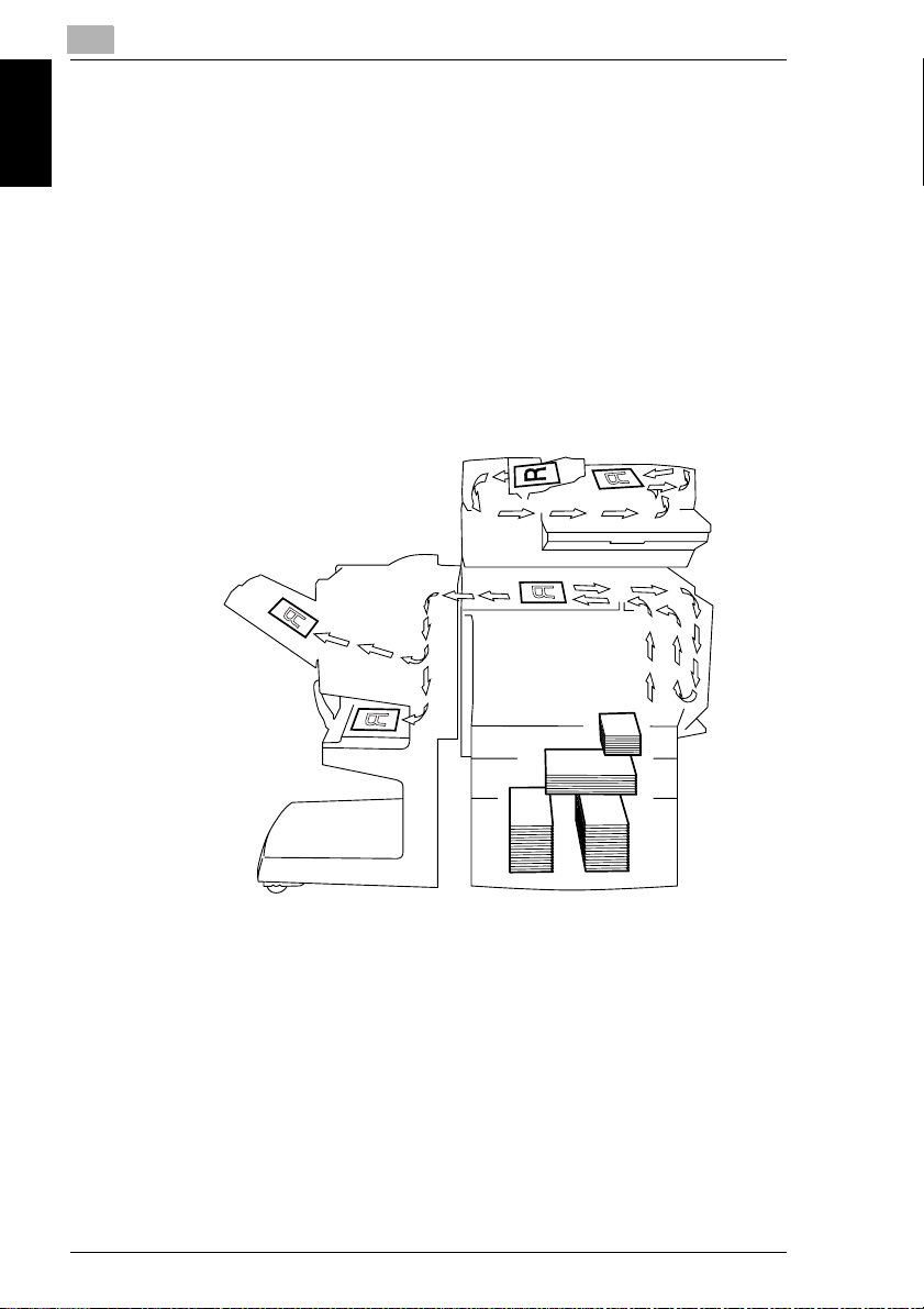
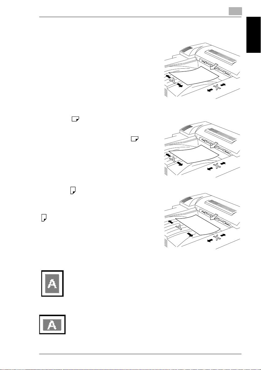
Paper Feeding
During printing, paper is supplied from the right side of the copier and fed into the
output tray on top or the output option at the left with the printed surface of the page
facing down. The paper feed direction is shown by the arrows in the diagram below.
During copying, paper is supplied from the right side of the copier and fed into the
Introduction Chapter 1
copy tray on the top or the output option at the left with the printed surface of the
copy facing down. The paper feed direction is shown by the arrows in the diagram
below.
1-4 CF2002/CF3102
Page 12
1.3 Explanation of Basic Concepts and Symbols
“Width” and “Length”
Whenever paper dimensions are mentioned in
this manual, the first value always refers to the
width of the paper (shown as “Y” in the
illustration) and the second to the length (shown
as “X”).
Paper Orientation
Lengthwise ( )
If the width (Y) of the paper is shorter than the
length (X), the paper has a vertical or portrait
orientation, indicated by either “L” or .
Crosswise ( )
If the width (Y) of the paper is longer than the
length (X), the paper has a horizontal or
landscape orientation, indicated by either “C” or
.
1
Introduction Chapter 1
Portrait and Landscape
Portrait
With the “portrait” orientation, the paper is vertical, like a portrait.
Landscape
With the “landscape” orientation, the paper is horizontal, like a
landscape.
CF2002/CF3102 1-5
Page 13
1
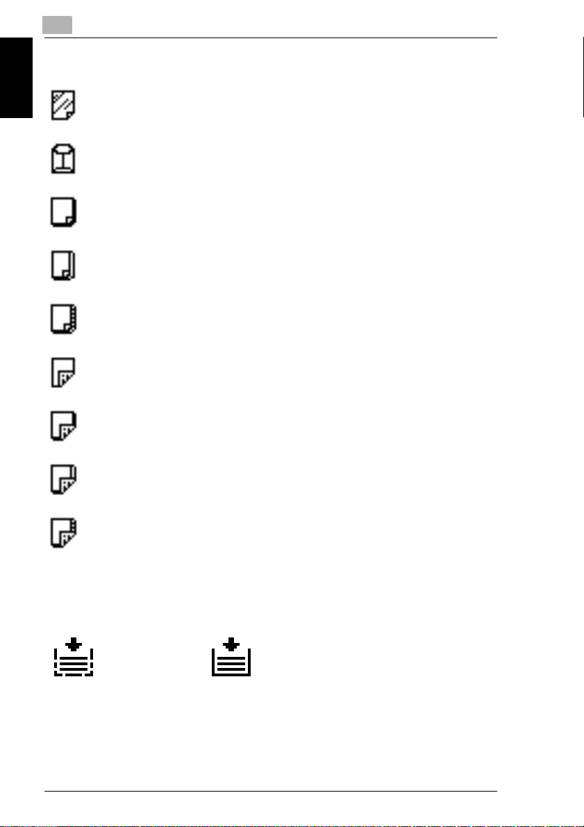
Display Icons
Overhead projector transparencies
Envelope
1.3 Explanation of Basic Concepts and Symbols
Introduction Chapter 1
Paper Supply Icons
The icons shown below are displayed to indicate the amount of paper that remains.
The paper is low. The paper is empty.
Thick paper 1
Thick paper 2
Thick paper 3
Second side of a double-sided copy on plain paper
Second side of a double-sided copy on thick paper 1
Second side of a double-sided copy on thick paper 2
Second side of a double-sided copy on thick paper 3
1-6 CF2002/CF3102
Page 14

1.4 Energy Star
®
1
1.4 Energy Star
As an ENERGY STAR® Partner, we have determined that this machine meets the
ENERGY STAR
What is an ENERGY STAR
An ENERGY STAR
switch to a “low-power mode” after a period of inactivity. An ENERGY STAR
product uses energy more efficiently, saves you money on utility bills and helps
protect the environment.
®
Guidelines for energy efficiency.
®
®
Product?
®
product has a special feature that allows it to automatically
®
1.5 Trademarks and Registered Trademarks
DiALTA is a registered trademark of Minolta Co., Ltd.
All other product names mentioned are trademarks or registered trademarks of their
respective companies
Introduction Chapter 1
CF2002/CF3102 1-7
Page 15

Introduction Chapter 1
1
1.5 Trademarks and Registered Trademarks
1-8 CF2002/CF3102
Page 16

2
Safety
Information
Safety Information Chapter 2
2
Page 17
2
2.1 Warning and Precaution Symbols
This section contains detailed instructions on the operation and maintenance of this
machine. To achieve optimum utility of this device, all operators should carefully
read and follow the instructions in this manual. Please keep this manual in a handy
place near the machine.
Please read the next section before using this device. It contains important information related to user
safety and preventing equipment problems.
Make sure you observe all of the precautions listed in this manual.
* Please note that some parts of the contents of this section may not correspond with the purchased
product.
2.1 Warning and Precaution Symbols
Ignoring this warning could cause serious injury or even death.
Ignoring this caution could cause injury or damage to property.
Safety Information Chapter 2
WARNING:
CAUTION:
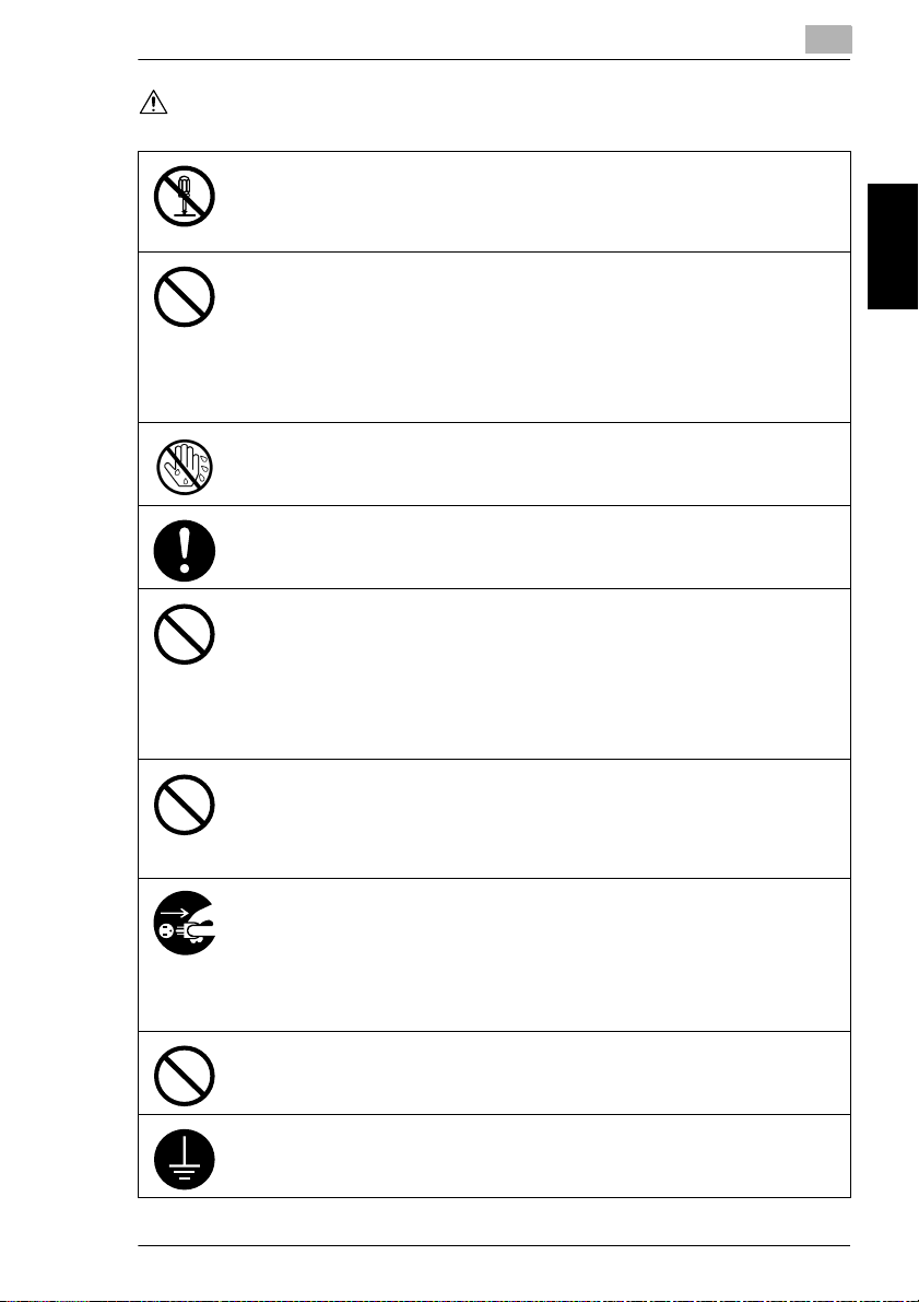
2.2 Meaning of Symbols
A triangle indicates a danger against which you should take precaution.
This symbol warns against cause burns.
A diagonal line indicates a prohibited course of action.
This symbol warns against dismantling the device.
A black circle indicates an imperative course of action.
This symbol indicates you must unplug the device.
2-2 CF2002/CF3102
Page 18
2.2 Meaning of Symbols
WARNING
• Do not modify this product, as a fire, electrical shock, or breakdown could result. If the
product employs a laser, the laser beam source could cause blindness.
• Do not attem pt to remove the covers and panel s which have been fixed to the produ ct.
Some products have a high-voltage part or a laser beam source inside that could
cause an electrical shock or blindness.
• Only use the power cord supplied in the package. Failure to use this cord could result
in a fire or electrical shock.
• Do not use the power cord for this copier with any other product. Using this copier’s
power cord with another product could result in fire or an electric shock.
• Use only the specified power source voltage. Failure to do that could result in a fire
or electrical shock.
• Do not use a multiple outlet adapter to connect any other appliances or machines.
Use of a power outlet for more than the marked current value could result in a fire or
electrical shock.
Do not unplug and plug in the power cord with a wet hand, as an electrical shock could
result.
2
Plug the power cord all the way into the power outlet. Failure to do this could result in a
fire or electrical shock.
• Do not scratch, abrade, place a heavy object on, heat, twist, bend, pull on, or damage
the power cord. Use of a damaged power cord (exposed core wire, broken wire, etc.)
could result in a fire or breakdown.
Should any of these conditions be found, immediately turn OFF the power switch,
unplug the power cord from the power outlet, and then call your authorized service
representative.
• Do not use an extension cord, in principle. Use of an extension cord could cause a
fire or electrical shock. Contact your authorized service representative if an extension
cord is required.
Do not place a flower vase or other container that contains water, or metal clips or other
small metallic objects on this product. Spilled water or metallic objects dropped inside
the product could result in a fire, electrical shock, or breakdown.
Should a piece of metal, water, or any other similar foreign matter get inside the product,
immediately turn OFF the power switch, unplug the power cord from the power outlet,
and then call your authorized service representative.
• Do not keep using this product, if this product becomes inordinately hot or emits
smoke, or unusual odor or noise. Immediately turn OFF the power switch, unplug the
power cord from the power outlet, and then call your authorized service
representative. If you keep on using it as is, a fire or electrical shock could result.
• Do not keep using this product, if this product has been dropped or its cover
damaged. Immediately turn OFF the power switch, unplug the power cord from the
power outlet, and then call your authorized service representative. If you keep on
using it as is, a fire or electrical shock could result.
Do not throw the toner cartridge or toner into an open flame. The hot toner may scatter
and cause burns or other damage.
Connect the power cord to an electrical outlet that is equipped with a grounding terminal.
Safety Information Chapter 2
CF2002/CF3102 2-3
Page 19
Safety Information Chapter 2
2
CAUTION
2.2 Meaning of Symbols
• Do not use flammable sprays, liquids, or gases near this product, as a fire could
result.
• Do not leave a toner unit or drum unit in a place within easy reach of children.
Licking or ingesting any of these things could injure your health.
• Do not let any object plug the ventilation holes of this product. Heat could accumulate
inside the product, resulting in a fire or malfunction.
• Do not install this product at a site that is exposed to direct sunlight, or near an air
conditioner or heating apparatus. The resultant temperature changes inside the
product could cause a malfunction, fire, or electrical shock.
• Do not place the product in a dusty place, or a site exposed to soot or steam, near a
kitchen table, bath, or a humidifier. A fire, electrical shock, or breakdown could result.
• Do not place this product on an unstable or tilted bench, or in a location subject to a
lot of vibration and shock. It could drop or fall, causing personal injury or mechanical
breakdown.
• After installing this product, mount it on a secure base. If the unit moves or falls, it may
cause personal injury.
• Do not store toner units and PC drum units near a floppy disk or watch that are
susceptible to magnetism. They could cause these products to malfunction.
The inside of this product has areas subject to high temperature, which may cause
burns. When checking the inside of the unit for malfunctions such as a paper misfeed,
do not touch the locations (around the fusing unit, etc.) which are indicated by a
“Caution! High Temperature!” warning label.
Do not place any objects around the power plug as the power plug may be difficult to pull
out when an emergency occurs.
The socket-outlet shall be installed near the machine and shall be easily accessible as
the power plug may be difficult to pull out when an emergency occurs.
• Always use this product in a well ventilated location. Operating the product in a poorly
ventilated room for an extended period of time could injure your health. Ventilate the
room at regular intervals.
• Whenever moving this product, be sure to disconnect the power cord and other
cables. Failure to do this could damage the cord or cable, resulting in a fire, electrical
shock, or breakdown.
• When moving this product, always hold it by the locations specified in the User
manual or other documents. If the unit falls it may cause severe personal injury. The
product may also be damaged or malfunction.
• Remove the power plug from the outlet more than one time a year and clean the area
between the plug terminals. Dust that accumulates between the plug terminals may
cause a fire.
• When unplugging the power cord, be sure to hold onto the plug. Pulling on the power
cord could damage the cord, resulting in a fire or electrical shock.
2-4 CF2002/CF3102
Page 20
2.3 Precautions for Routine Use
2.3 Precautions for Routine Use
• Do not store toner units, PC drum units, and other supplies and consumables in a
place subject to direct sunlight and high temperature and humidity, as poor image
quality and malfunction could result.
• Do not attempt to replace the toner unit and PC drum unit in a place exposed to direct
sunlight. If the PC drum is exposed to intense light, poor image quality could result.
• Do not unpack a toner unit or PC drum unit until the very time of use. Do not leave an
unpacked unit standing. Install it immediately or poor image quality could result.
• Do not keep toner units and PC drum units in an upright position or upside down, as
poor image quality could result.
• Do not throw or drop a toner unit or PC drum unit as poor image quality could result.
• Do not use this product in an area where ammonia or other gases or chemicals are
present. Failure to do so may shorten the service life of the product, cause damage
or decrease performance.
• Do not use this product in an environment with a temperature outside the range
specified in the User manual, as a breakdown or malfunction could result.
• Do not attempt to feed stapled paper, carbon paper or aluminum foil through this
product, as a malfunction or fire could result.
Do not touch or scratch the surface of the toner unit, developing roller and the PC drum,
as poor image quality could result.
Use the supplies and consumables recommended by the dealer. Use of any supply or
consumable not recommended could result in poor image quality and breakdown.
2.4 USER INSTRUCTIONS FCC PART 15 - RADIO FREQUENCY DEVICES (For U.S.A. Users)
2
Safety Information Chapter 2
NOTE: This equipment has been tested and found to comply with the limits for a
Class A digital device, pursuant to Part 15 of the FCC Rules.
These limits are designed to provide reasonable protection against harmful
interference when the equipment is operated in a commercial environment. This
equipment generates, uses and can radiate radio frequency energy and, if not
installed and used in accordance with the instruction manual, may cause harmful
interference to radio communications. Operation of this equipment in a residential
area is likely to cause harmful interference in which case the user will be required
to correct the interference at his own expense.
WARNING: The design and production of this unit conform to FCC regulations, and
any changes or modifications must be registered with the FCC and are subject to
FCC control. Any changes made by the purchaser or user without first contacting
the manufacturer will be subject to penalty under FCC regulations.
CF2002/CF3102 2-5
Page 21

2
2.5 INTERFERENCE-CAUSING EQUIPMENT STANDARD
2.5 INTERFERENCE-CAUSING EQUIPMENT
STANDARD
(ICES-003 IS-SUE 3) (For Canada Users)
This Class A digital apparatus complies with Canadian ICES-003.
Cet appareil numérique de la classe A est conforme à la norme NMB-003 du
Canada.
2.6 For Users in countries not subject to Class B regulations
WARNING
This is a Class A product. In a domestic environment this product may cause radio
interference in which case the user may be required to take adequate measures.
2.7 LED Radiation Safety
Safety Information Chapter 2
This product is a copier which operates by means of a LED (light emitting diodes)
exposure system. There is no possibility of danger from the LED optical radiation,
because the LED optical radiation level does not exceed the accessible radiation
limit of class 1 under all conditions of operation, maintenance, service and failure.
2.8 Ozone Release
Locate the machine in a Well Ventilated Room
A negligible amount of ozone is generated during normal operation of this machine.
An unpleasant odor may, however, be created in poorly ventilated rooms during
extensive machine operations. For a comfortable, healthy and safe operating
environment, it is recommended that the room be well ventilated.
Placer l’appareil dans une pièce largement ventilée
Une quantité d’ozone négligable est dégagée pendant le fonctionnement de
l’appareil quand celui-ci est utilisé normalement. Cependant, une odeur
désagréable peut être ressentie dans les pièces dont l’aération est insuffisante et
lorsque une utilisation prolongée de l’appareil est effectuée. Pour avoir la certitude
de travailler dans un environnment réunissant des conditions de confort, santé et
de sécurité, il est préférable de bien aérer la pièce ou se trouve l’appareil.
2-6 CF2002/CF3102
Page 22

3
Precautions
Precautions Chapter 3
3
Page 23

3
3.1 Installation Precautions
3.1 Installation Precautions
Installation Site
To ensure utmost safety and prevent possible malfunctions, install the copier in a
location that meets the following requirements.
-
A location away from curtains, etc. that may catch fire and burn easily
-
A location that is not exposed to water or other liquids
-
A location free from direct sunlight
-
A location out of the direct airflow of an air conditioner or heater, and not
exposed to extremely high or low temperatures
-
A well-ventilated location
-
A location that is not exposed to high humidity
-
A location that is not extremely dusty
-
A location not subjected to undue vibrations
-
A stable and level location
-
A location where ammonia or other organic gases are not generated
Precautions Chapter 3
-
A location that does not put the operator in the direct airflow of exhaust from the
copier
-
A location that is not near any kind of heating devices
Power Source
The power source requirements are as follows.
Voltage fluctuation: Maximum ±10%
G
(AC 127 V areas only: Between –10% and +6%)
Frequency fluctuation: Maximum ±0.3%
G
Use a power source with as little voltage or frequency fluctuations as possible.
❍
3-2 CF2002/CF3102
Page 24
3.1 Installation Precautions
3
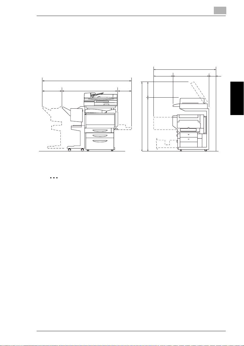
Space Requirements
To ensure easy copier operation, supply replacement, and maintenance, adhere to
the recommended space requirements detailed below.
56-1/2 (1,432)
4
(100)
11-1/4
(285)
72-1/2 (1,839)
50 (1,271)
11-1/4
(283)
60 (1,521)
14
45-3/4
21-1/4
(540)
(358)
(1,163)
31-1/4
(792)
Unit: inch (mm)
✎
Note
Be sure to allow a clearance of 4 in. (100 mm) or more at the back of the copier
for the ventilation duct.
Precautions Chapter 3
CF2002/CF3102 3-3
Page 25

3
3.2 Operation Precautions
3.2 Operation Precautions
Operating environment
The environmental requirements for correct operation of the copier are as follows.
Temperature: 50°F (10°C) to 86°F (30°C) with fluctuations of no more than 50°F
G
(10°C) within an hour
Humidity: 10% to 80% with fluctuations of no more than 20% within an hour
G
Proper use
To ensure the optimum performance of the copier, follow the precautions listed
below.
-
Never place heavy objects on the original glass or subject it to shocks.
-
Never open any copier doors or turn off the copier while it is making copies;
otherwise, a paper jam will occur.
-
Never bring any magnetized object or use flammable sprays or liquids near the
copier.
✚
Precautions Chapter 3
Always make sure that the power plug is completely plugged into the electrical
outlet.
-
Always make sure that the copier’s power plug is visible and not hidden by the
copier.
✚
Always unplug the copier from the electrical outlet if the unit is not to be used for
a long period of time.
✚
Always provide good ventilation when making a large number of continuous
copies.
3-4 CF2002/CF3102
Page 26

3.2 Operation Precautions
CAUTION
If the ventilation duct at the top of the copier becomes blocked, the inside of
the copier will accumulate heat, resulting in a malfunction or fire.
Do not place any objects over the ventilation duct.
➜
CAUTION
The area around the fusing unit is extremely hot.
Be careful not to touch any parts around the fusing unit, other than those
➜
indicated in this manual, in order to reduce the risk of burns. Be especially
careful not to touch parts marked with warning labels, and their surrounding
areas.
If you get burnt, immediately cool the skin under cold water, and then seek
➜
professional medical advice.
Transporting the copier
If you need to transport the copier over a long distance, consult your technical
representative.
3
Precautions Chapter 3
Care of copier supplies
Use the following precautions when handling the copier supplies (toner cartridge,
paper, etc.).
✚
Store the supplies in a location that meets the following requirements.
Free from direct sunlight
Away from any heating apparatus
Not subjected to high humidity
Not extremely dusty
✚
Store in a sealed plastic bag in a cool, dark place paper that has been removed
from its wrapper but not loaded into the copier.
-
Only use toner that has been manufactured specifically for this copier. Never
use other types of toner.
-
Keep all supplies out of the reach of children.
CF2002/CF3102 3-5
Page 27

3
CAUTION
Precautions for handling toner:
Be careful not to spill toner inside the copier or get toner on your clothes or
➜
hands.
If your hands become soiled with toner, immediately wash them with soap and
➜
water.
If toner gets in your eyes, immediately flush them with water, and then seek
➜
professional medical advice.
Storage of copies
✚
Copies that are to be kept for a long time should be kept where they are not
exposed to light in order to prevent them from fading.
-
Adhesive that contains solvent (e.g., spray glue) may dissolve the toner on
copies.
Precautions Chapter 3
-
Color copies have a thicker layer of toner than normal black-and-white copies.
Therefore, when a color copy is folded, the toner at the fold may peel off.
3.2 Operation Precautions
3-6 CF2002/CF3102
Page 28

3.3 Legal Restrictions on Copying
3
3.3 Legal Restrictions on Copying
Certain types of documents must never be copied with the purpose or intent to pass
copies of such documents off as the originals.
The following is not a complete list, but is meant to be used as a guide to
responsible copying.
<Financial Instruments>
Personal checks
G
Travelers checks
G
Money orders
G
Certificates of deposit
G
Bonds or other certificates of indebtedness
G
Stock certificates
G
<Legal Documents>
Food stamps
G
Postage stamps (canceled or uncanceled)
G
Checks or drafts drawn by government agencies
G
Internal revenue stamps (canceled or uncanceled)
G
Passports
G
Immigration papers
G
Motor vehicle licenses and titles
G
House and property titles and deeds
G
<General>
Identification cards, badges, or insignias
G
Copyrighted works without permission of the copyright owner
G
In addition, it is prohibited under any circumstances
currencies, or works of art without permission of the copyright owner.
When in doubt about the nature of a document, consult with legal counsel.
to copy domestic or foreign
Precautions Chapter 3
CF2002/CF3102 3-7
Page 29

Precautions Chapter 3
3
3.3 Legal Restrictions on Copying
3-8 CF2002/CF3102
Page 30

4
Part Names
and Their
Functions
4
Part Names and Their Functions Chapter 4
Page 31

4
4.1 Components and Their Functions
4.1 Components and Their Functions
7
6
5
No. Part Name Description
1 Duplexing Document Feeder
AFR-18 (optional)
2 Scanner SC-1 Scans the document
3 Copier printer section Prints the image scanned with the scanner
4 Copy Desk CD-2M (optional) The printer can be set up on the copy desk.
Part Names and Their Functions Chapter 4
5 Large Capacity Cabinet
PF-121 (optional)
6 Finisher FN-116 (optional) Finishes copies according to the selected Finishing setting
7 Option Tray JS-100
(optional)
Automatically feeds and scans one document sheet at a time,
and automatically turns over double-sided documents and
scans them
Referred to as the
manual
Referred to as the
the combination of the scanner and the printer is referred to as
copier
the
Referred to as the
the combination of the scanner and the printer is referred to as
the
By setting up the printer on the copy desk, the printer can be
placed on the floor instead of on a desk, keeping the entire
surface of the desk free.
Referred to as the
Equipped with a paper drawer that can supply 2,500 sheets of
paper
Referred to as the
manual
(sorting or stapling), then feeds out the pages
• If the finisher is installed, the printer must be installed on the
If finisher FN-116 is installed, the number of paper output trays
can be increased.
.
copier
.
copy desk, on the large capacity cabinet or over a paper feed
unit combined with the copy table.
1
2
3
4
duplexing document feeder
scanner
throughout the manual; in addition,
printer
throughout the manual; in addition,
copy desk
large capacity cabinet
throughout the manual
throughout the
throughout the
4-2 CF2002/CF3102
Page 32

4.1 Components and Their Functions
13
4
8
12
9
10
11
No. Part Name Description
8 Original Cover OC-2
(optional)
9 Duplex Unit AD-14 (optional) Turns over copies, allowing double-sided copies to be made
10 Paper Feed Unit
PF-118 (optional)
11 Copy Table CT-2 (optional) A paper feed unit can be set up on the copy table, and then the
12 Finisher FN-8 (optional) Finishes copies according to the selected finishing mode
13 Copier Stand CS-2 (optional) Reduces the installation area required for the equipment if the
Presses down on the loaded document to keep it in place
Referred to as the
automatically.
• If a printer controller (CN3102Pro or CN3102e) and the
duplex unit are installed on the CF3102, the memory must be
expanded. If the optional memory is not installed, automatic
double-sided copying cannot be performed.
Referred to as the duplex unit throughout the manual
Equipped with a paper drawer that can supply 500 sheets of
paper; up to two paper feed units can be installed.
Referred to as the
printer can be set up on the top.
By setting up the printer on the copy table, the printer can be
placed on the floor instead of on a desk, keeping the entire
surface of the desk free.
Referred to as the
(sorting, stapling, hole-punching or binding), then feeds out the
pages
• The hole-punching function is only available if the optional
punch kit (PK-4) is installed onto finisher FN-8. If the finisher
is installed, the printer must be installed on the copy desk, on
the large capaci ty cabinet or over a paper fee d unit combined
with the copy table.
scanner is installed on the top of the stand and the printer is
installed on the inside
Referred to as the
original cover
paper feed unit
copy table
copier stand
throughout the manual
throughout the manual
throughout the manual
throughout the manual
Part Names and Their Functions Chapter 4
CF2002/CF3102 4-3
Page 33
4
No. Part Name Description
14 Punch KIT PK-4 (optional)* Allows the hole-punching function to be used if installed onto
15 Memory M256-2
(US, Canada: Standard,
Others: Optional)
16 Hard Disk Drive HDD-5
(optional)*
17 Printer Controller
CN3101e (optional)*
18 Printer Controller
CN3102Pro (optional)*
19 Printer Controller
CN3102e (optional)*
* The internal options are not shown.
finisher FN-8
Increases the memory of the copier to 512 MB (256 MB
standard memory + 256 MB expanded memory)
By expanding the memory, the number of pages that can be
stored in the memory can be increased. (Refer to Supplemental
Table 1.)
Referred to as the
Allows more pages to be stored (Refer to Supplemental Table
1.)
In addition, by installing hard disk drive HDD-5 and the optional
memory, the “Distribution” function can be used.
Referred to as the
Internal printer controller that allows the copier to be used as
both a color printer and a color scanner configured into a
computer network
For more details, refer to the manual of the printer controller.
External printer controller that allows the copier to be used as
both a color printer and a color scanner configured into a
computer network
For more details, refer to the manual of the printer controller.
Stationary printer controller that allows the copier to be used as
both a color printer and a color scanner configured into a
computer network
For more details, refer to the manual of the printer controller.
4.1 Components and Their Functions
memory
throughout the manual
hard disk
throughout the manual
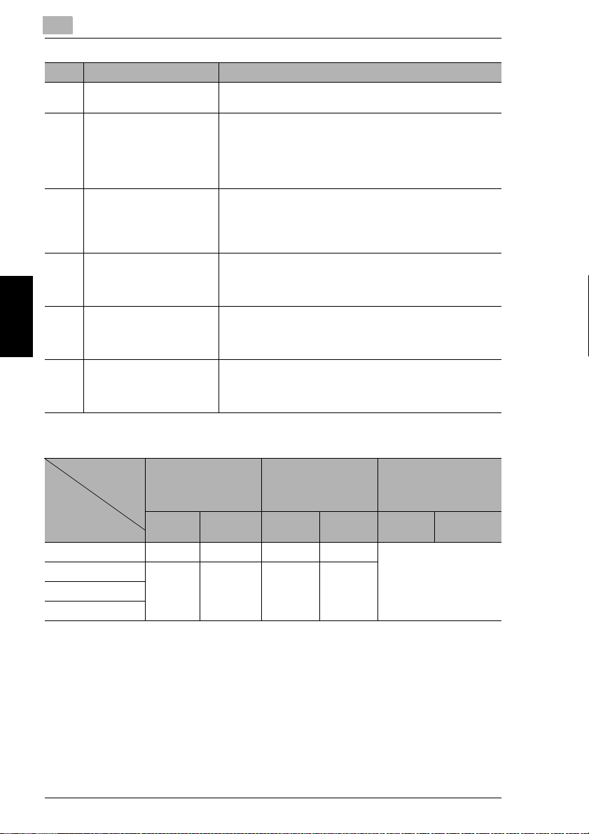
Supplemental Table 1
Number of Document
Pages Stored
Document Type
Text only 60 sheets 197 sheets 137 sheets 400 sheets Maximum 2,000 sheets
Text and images 20 sheets 149 sheets 46 sheets 340 sheets
Part Names and Their Functions Chapter 4
Photographs
Maps
* The number of document pages that can be stored was calculated based on our standard document
page. The number of pages that can be stored will vary depending on the document.
Standard Configuration With Optional Memory
Color Black &
white
Installed
(US, Canada: Standard,
Others: Optional)
Color Black &
white
With Optional Memory
and the Hard Disk
Installed
Color Black &
white
4-4 CF2002/CF3102
Page 34

4.2 Parts Names and Their Functions
4.2 Parts Names and Their Functions
Outside of Copier
8
4
7
6
5
1
2
3
4
*The illustration above shows the optional original cover, copier stand and copy
desk installed.
No. Part Name Description
1 Right-side door Opened when clearing misfeeds
2 Manual bypass tray Used for manual feeding of paper
3 Power switch Used to turn the copier on and off
4 Lower right-side door Opened when clearing misfeeds
5 2nd drawer Holds up to 500 sheets of paper
6 1st drawer Holds 250 sheets of paper
7 Front door Opened when replacing a toner cartridge (See p. 6-5)
8 Copy output tray Collects copies fed out of the copier facing down
The paper is fed one sheet at a time.
Special paper can be loaded.
(See section 3.5 in the Basic Operations volume.)
(See section 1.5 in the Basic Operations volume.)
The paper size can be adjusted freely.
(See section 3.5 in the Basic Operations volume.)
The paper size can be adjusted freely.
Special paper can be loaded.
(See section 3.5 in the Basic Operations volume.)
Part Names and Their Functions Chapter 4
CF2002/CF3102 4-5
Page 35

4
4.2 Parts Names and Their Functions
9
12
Envelope
OHP
Thick3
Thick3
Plain
Thick2
Plain
Thick1
Thick1
Thick2
16
10
11
15
*The illustration above shows the optional original cover, copier stand and copy
desk installed.
No. Part Name Description
9 Original Cover (optional) Presses the document against the original glass
Part Names and Their Functions Chapter 4
10 Document scale Used to align the document
11 Original glass When manually feeding the document, place it on the glass so
12 Control panel Used to start copying or to make settings
13 Media type selection dial Used to specify the type of paper loaded into the 1st drawer
14 1st drawer
Paper-empty indicator
15 2nd drawer
Paper-empty indicator
16 Left-side door Opened when servicing the copier
(See section 4.2 in the Basic Operations volume.)
the document can be scanned.
Place the document face down on the glass.
(See section 4.2 in the Basic Operations volume.)
(See section 1.3 in the Basic Operations volume.)
Indicates the amount of paper remaining
• Flashing: Indicates that there is little paper remaining
• Lit: Indicates that the paper is empty
Replenish the paper.
13
14
4-6 CF2002/CF3102
Page 36
4.2 Parts Names and Their Functions
23
22
21
20
19
4
18
17
*The illustration above shows the optional original cover, copier stand and copy
desk installed.
No. Part Name Description
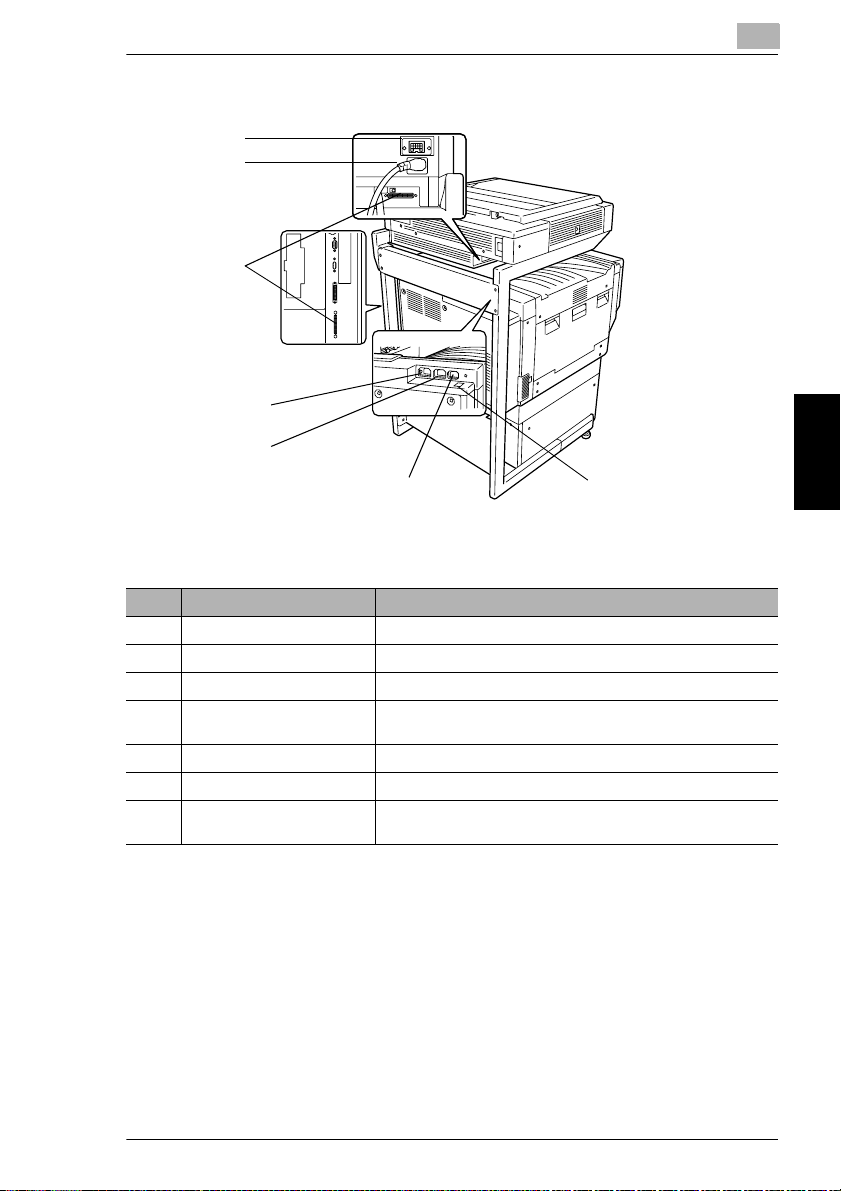
17 Finisher connector Used for connecting the finisher hookup cord
18 Printer power cord socket Used for connecting the printer’s power cord
19 Scanner power cord outlet Used for connecting the scanner’s power cord
20 Power cord soc ket for Printer
Controller CN3102e
21 Scanner connector Used for connecting the scanner hookup cord
22 Scanner power cord socket Used for connecting the scanner’s power cord
23 Duplexing Do cument Feeder
conector
Used for connecting the power cord for printer controller
CN3102e
Used for connecting the duplexing document feeder hookup
cord
Part Names and Their Functions Chapter 4
CF2002/CF3102 4-7
Page 37
4
Supplies and Parts
4.2 Parts Names and Their Functions
1
2 3
4
7
5
8
9
10
6
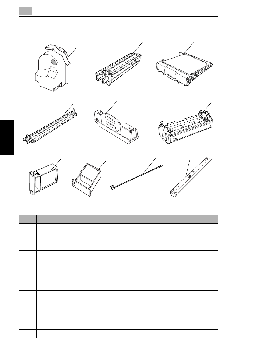
No. Part Name Description
Part Names and Their Functions Chapter 4
1 Toner Cartridge There are four toner cartridges: cyan (C), magenta (M), yellow
2 Imaging Unit Generates the copied image
3 Image transfer belt unit Layers onto the image transfer belt each of the single colors of
4 Image transfer roller unit Transfers onto the paper a full-color image generated by the
5 Waste-toner bottle Collects waste toner
6 Fusing unit Fuses the transferred toner to the paper
7 Ozone filter Collects the ozone generated in the copier
8 Filter Collects the toner dust generated in the copier
9 LED-cleaning tool Used to clean the surface of the LED unit, for example, when
10 Dust remover Collects the dust generated in the copier
(Y) and black (BK). The combination of the four toners
generates full-color images.
the image generated by the imaging unit in order to create a fullcolor image
image transfer belt unit
replacing the image transfer belt unit
4-8 CF2002/CF3102
Page 38

4.2 Parts Names and Their Functions
Inside of Copier
6
4
5
4
3
No. Part Name Description
1 Upper right-side door Opened when replacing the fusing unit or clearing misfeeds
2 LED-cleaning tool Used to clean the surface of the LED unit, for example, when
3 Imaging unit removal bracket Used to remove the imaging unit
4 Charger-cleaning tool Used to clean the electrostatic charger wire, for example, when
5 Imaging unit release lever Used to install and replace the imaging unit
6 Toner cartridge
compartments
2
replacing the image transfer belt unit
incorrect copies are produced
Contains a toner cartridge for each color
1
Part Names and Their Functions Chapter 4
CF2002/CF3102 4-9
Page 39

4
4.2 Parts Names and Their Functions
Options
1
13
12
11
10
9
8
Duplexing Document Feeder
No. Part Name Description
1 Adjustable document guide Adjust to the width of the document.
2 Document feed tray Load the documents to be copied face up.
3 Document output tray Collects documents that have been copied
4 Misfeed-clearing cover Opened when clearing a misfed document
(See section 4.2 in the Basic Operations volume.)
(See section 4.2 in the Basic Operations volume.)
2
3
4
5
6
7
Duplex Unit
No. Part Name Description
Part Names and Their Functions Chapter 4
5 Duplex unit door Opened when clearing a paper misfeed within the duplex unit
Paper Feed Unit
No. Part Name Description
6 3rd drawer Holds up to 500 sheets of paper
7 4th drawer
As many as two units can be installed.
The paper size can be adjusted freely.
4-10 CF2002/CF3102
Page 40

4.2 Parts Names and Their Functions
Finisher (FN-8)
No. Part Name Description
8 Lower paper output tray
(bound paper tray)
9 Front door Opened when replacing the staple cartridge
10 Paper output tray
(elevated tray)
11 Upper door Opened when clearing a paper misfeed within the finisher
12 Paper guide Opened when clearing a paper misfeed within the finisher
13 Transport guide Opened when clearing a paper misfeed within the finisher
Collects copies that were bound
Collect copies
4
CF2002/CF3102 4-11
Part Names and Their Functions Chapter 4
Page 41

4
4.2 Parts Names and Their Functions
18
17
16
15
19
Large Capacity Cabinet
No. Part Name Description
14 3rd drawer Holds up to 2,500 sheets of paper
(See section 3.5 in the Basic Operations volume.)
Finisher (FN-116)
No. Part Name Description
15 Front door Opened when clearing a paper misfeed within the finisher
Part Names and Their Functions Chapter 4
16 Secondary paper output tray
(sorted copies)
17 Primary paper output tray
(non-sorted copies)
18 Upper cover Opened when clearing a paper misfeed within the finisher
Collects copies that are sorted
Collects copies that are not sorted (made with the “Non-Sort”
setting)
14
Option Tray
No. Part Name Description
19 Option Tray (optional) Collects copies
4-12 CF2002/CF3102
Page 42

5
Utility Mode
Operations
5
Utility Mode Operations Chapter 5
Page 43

5
5.1 Utility Screen
5.1 Utility Screen
The functions available on the Utility screen, displayed by pressing the [Utility] key,
are described below.
If the [Utility] key is pressed, the following screen appears.
(Refer to p. 5-3)
“Reset Mode” function: The initial mode settings, selected after the copier is
G
reset, can be changed.
“Job Memory Input” function: Up to 10 copy modes can be stored as copy
G
programs.
(Refer to p. 5-7)
The various functions can be set according to the user’s needs.
G
There are two User’s Choice screens.
G
The functions that can be set while a job is printing are on the User’s Choice:
❍
1 screen, and the functions that can be set while the copier is waiting to print
are on the User’s Choice: 2 screen.
(Refer to p. 5-32)
The various counters, showing the number of copies that have been made since
G
the copier was installed, can be viewed.
Utility Mode Operations Chapter 5
The level of use for the various supplies and parts can be checked.
G
The various copy programs stored with the “Job Memory Input” function,
G
described above, can be recalled.
The Administrator mode allows the use of the copier to be controlled, by
G
allowing various functions to be set according to the use.
The administrator access code (4-digit password) must be entered in order to
G
set the Administrator mode functions. For details on the administrator access
code, contact the technical representative.
(Refer to p. 5-34)
(Refer to p. 5-6)
(Refer to p. 5-35)
5-2 CF2002/CF3102
Page 44
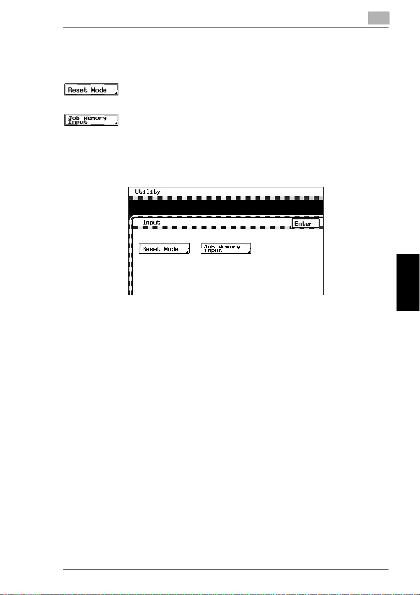
5.1 Utility Screen
Specifying the Input Screen Functions
The following two functions are available on the Input screen (when [Input] is
touched).
(Refer to page 5-4)
The initial mode settings, selected after the copier is reset, can be changed.
G
(Refer to p. 5-5)
User-specified copy modes can be stored as copy programs.
G
Up to 10 specified copy modes can be stored as copy programs. These stored
G
copy programs can be recalled by touching [Copy Program Recall] on the Utility
screen.
5
CF2002/CF3102 5-3
Utility Mode Operations Chapter 5
Page 45
5
Specifying the Initial Mode Settings (“Reset Mode” Function)
The mode selected when the power switch is turned on (set to “I”) is called the initial
mode.
The settings for the mode selected when the power switch is turned on (set to “I”)
can be specified using the “Reset Mode” function.
To specify the initial mode settings
1
Select the desired Copy mode settings.
For details on selecting Copy mode settings, refer to “Specifying Copy
❍
Settings” in the Basic Operations volume.
2
Press the [Utility] key.
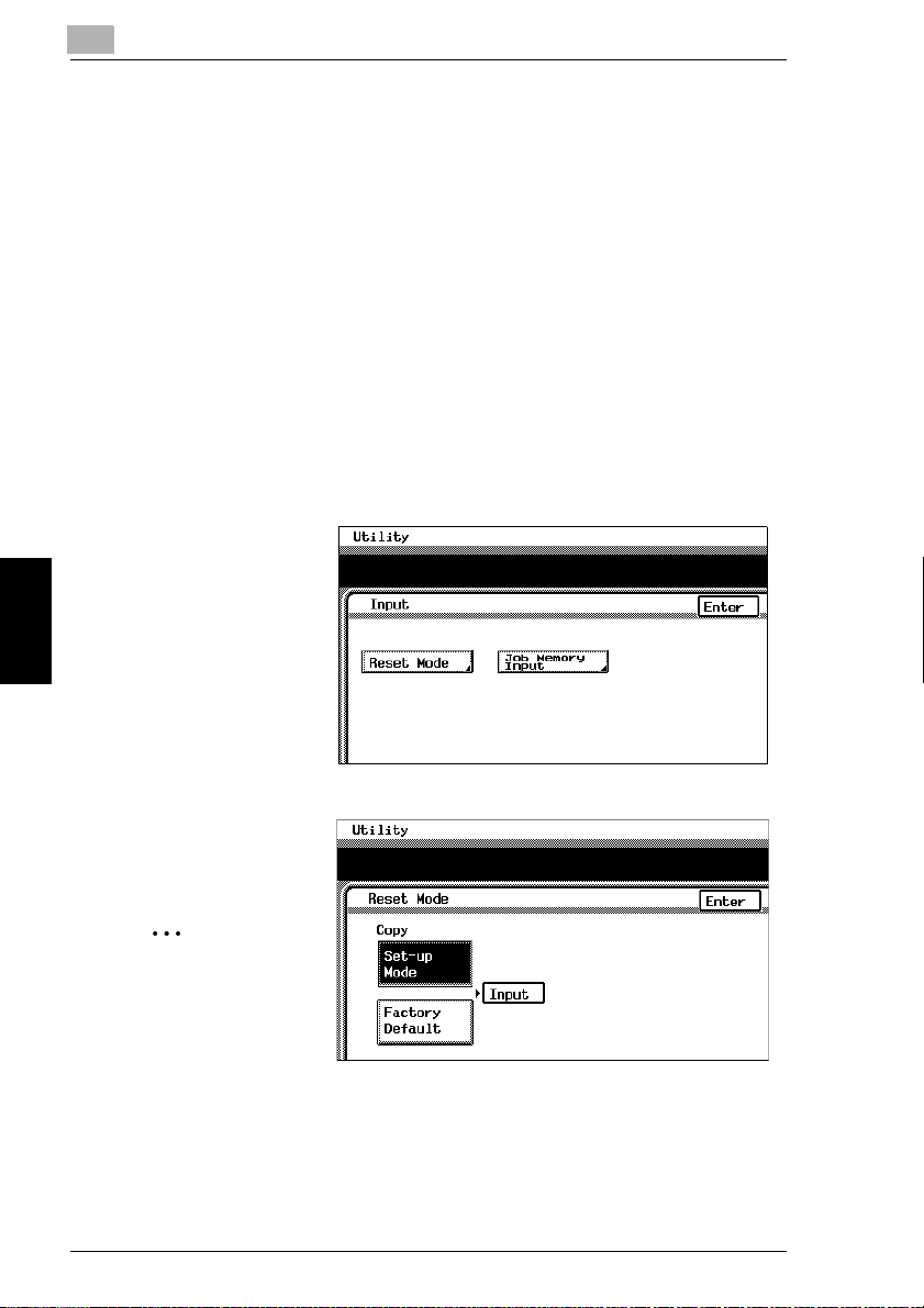
3
Touch [Input].
4
Touch [Reset Mode].
5.1 Utility Screen
5
Touch [Set-up Mode].
6
Touch [Input].
✎
Utility Mode Operations Chapter 5
Note
If [Set-up Mode] is
selected, the
current Copy mode
settings are stored
as the initial mode
settings.
7
Touch [Enter], and then touch [Enter] again in the screen that appears.
8
Touch [Fin. Time].
5-4 CF2002/CF3102
Page 46
5.1 Utility Screen
Using Copy Programs
A user-specified copy mode can be stored as a copy program.
Each of the 10 copy programs that can be stored can be given a name (up to 9
characters long).
To store a copy program
1
Select the desired Copy mode settings.
For details on selecting Copy mode settings, refer to “Specifying Copy
❍
Setting” in the Basic Operations volume.
2
Press the [Utility] key.
3
Touch [Input].
4
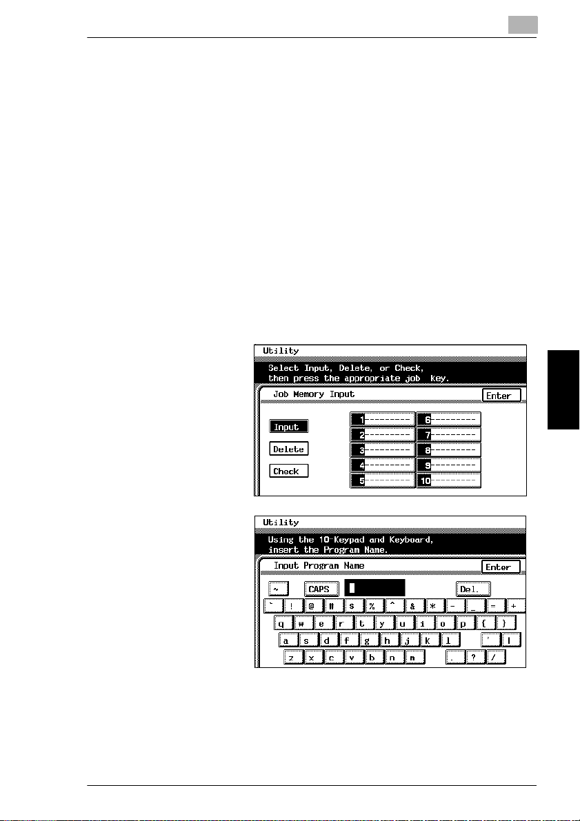
Touch [Job Memory Input].
5
Touch the number of
the program where you
wish to store the
settings.
A screen appears,
allowing you to enter
the name of the
program.
5
6
Touch the letters and
numbers to enter a
name (9 characters
long) for the copy job,
and then touch [Enter].
❍
To delete a copy program
Touch [Delete], and then touch the number of the program that you wish to
delete. When the number of the program is selected, the program is deleted.
❍
To check the specified settings of a program
Touch [Check], and then touch the number of the program that you wish to
check. The specified Copy mode settings are displayed. To return to the Job
Memory Input screen, touch [Enter].
CF2002/CF3102 5-5
Utility Mode Operations Chapter 5
Page 47
5
7
Touch [Enter], and then touch [Enter] again in the screen that appears.
8
Touch [Fin. Time].
The Basic screen appears again.
To recall a stored copy program and use it to make copies
The stored copy programs can be recalled to be used again, as necessary.
Recall the copy programs by touching [Copy Program Recall] on the Utility screen.
1
Press the [Utility] key.
2
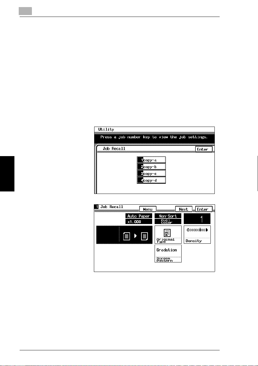
Touch [Copy Program Recall].
3
Touch the number of
the program that you
wish to recall.
The copy program
settings appear.
5.1 Utility Screen
4
Check that the copy
program settings that
appear are the ones
that you wish to use,
and then touch [Enter].
The Copy mode
settings change to the
ones that are recalled.
Utility Mode Operations Chapter 5
If the displayed copy
program settings are
not the ones that you
wish to use, touch [Menu].
The Job Recall screen appears again. Touch the correct number of the program
that you wish to recall.
5
Press the [Start] key. The copy job is queued for printing with the recalled Copy
mode settings.
5-6 CF2002/CF3102
Page 48

5.2 Specifying Default Settings (“User’s Choice” Functions)
5.2 Specifying Default Settings (“User’s Choice”
Functions)
With the User’s Choice function, the initial mode settings can be customized
according to how the copier is to be used.
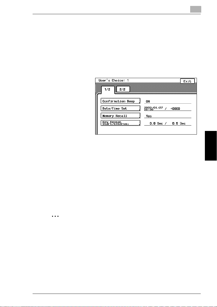
User’s Choice: 1 Screens
(Refer to p. 5-10)
This function is used to specify whether or not a confirmation beep is sounded
G
each time a key in the operation panel is pressed.
(Refer to p. 5-11)
This function is used to set the current date and time.
G
(Refer to p. 5-13)
This function is used to set the memory recall feature, which allows settings
G
from past copy jobs to be recalled.
(Refer to p. 5-15)
This function is used to specify the length of time until the repeat feature for a
G
key starts and the length of the time that a key must be held down between
subsequent repeats.
(Refer to p. 5-16)
This function is used to specify the length of time after the last operation until all
G
functions return to their default settings.
(Refer to p. 5-17)
This function is used to specify the length of time after the last operation until
G
the copier automatically enters Energy Saver mode.
(Refer to p. 5-18)
This function is used to specify the length of time after the last operation until
G
the copier automatically enters Sleep mode.
5
Utility Mode Operations Chapter 5
CF2002/CF3102 5-7
Page 49
5
This function is used to specify whether all modes and functions are
G
automatically reset when the magnetic card is removed from the data controller
or the key counter is removed.
This function is used to specify the length of time that the message requesting
G
confirmation to cancel the Enlarge Display mode is displayed.
5.2 Specifying Default Settings (“User’s Choice” Functions)
(Refer to p. 5-19)
(Refer to p. 5-20)
Utility Mode Operations Chapter 5
5-8 CF2002/CF3102
Page 50
5.2 Specifying Default Settings (“User’s Choice” Functions)
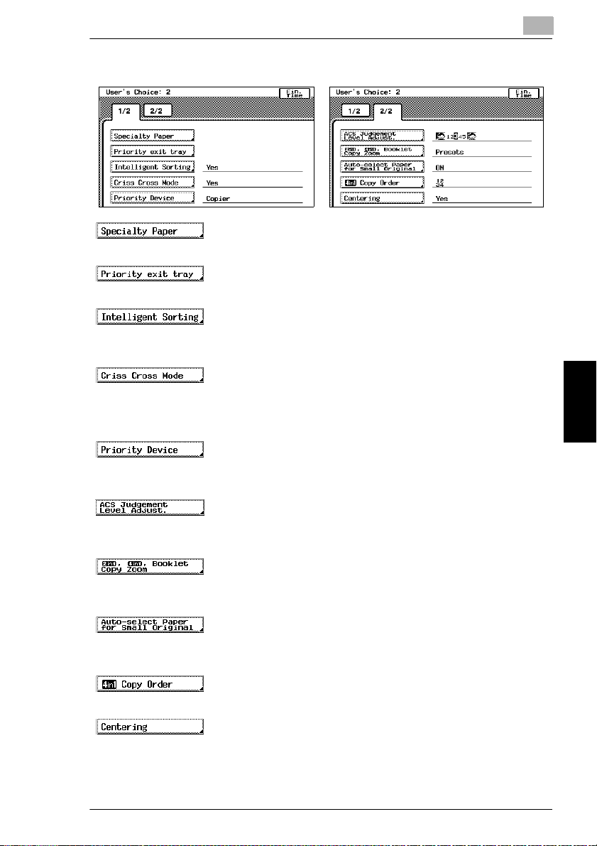
User’s Choice: 2 Screens
(Refer to p. 5-21)
This function is used to specify the special paper settings for each paper drawer.
G
(Refer to p. 5-23)
This function is used to set the priority order of the paper output trays.
G
(Refer to p. 5-24)
This function is used to specify whether the “Sort” setting is automatically
G
selected if the document consists of 2 or more pages.
(Refer to p. 5-25)
This function is used to set whether or not copies will be sorted in a crisscross
G
pattern if the necessary conditions are met while using the “Sort” or “Group”
settings.
(Refer to p. 5-26)
This function is used to specify the print timing for print jobs that have been
G
received.
(Refer to p. 5-27)
This function is used to adjust the level for detecting whether a document will be
G
copied in color or in black and white.
(Refer to p. 5-28)
This function is used to specify the zoom ratios for 2in1 and 4in1 copying, and
G
booklet binding.
(Refer to p. 5-29)
This function is used to specify how small-sized documents are printed using
G
the “Auto Paper” setting.
(Refer to p. 5-30)
This function is used to specify the page order for 4in1 copying.
G
(Refer to p. 5-31)
This function is used to specify whether or not the image is centered when the
G
document is smaller than the paper.
5
Utility Mode Operations Chapter 5
CF2002/CF3102 5-9
Page 51

5
To set the “Confirmation Beep” function
This function is used to specify whether or not a confirmation beep is sounded each
time a key in the operation panel is pressed. (The default setting is [ON].)
1
Press the [Utility] key.
2
Touch [User’s Choice: 1].
3
Touch [Confirmation
Beep].
4
Select the desired
setting.
5
Touch [Enter].
5.2 Specifying Default Settings (“User’s Choice” Functions)
6
Touch [Fin. Time], and
then touch [Fin. Time]
again in the screen that
appears.
Utility Mode Operations Chapter 5
5-10 CF2002/CF3102
Page 52
5.2 Specifying Default Settings (“User’s Choice” Functions)
To set the “Date/Time Set” function
This function is used to set the current date and time. In addition, the time zone can
be set between -1200 and +1200 (in 30 minute intervals). (The default setting is
[+0000].)
1
Press the [Utility] key.
2
Touch [User’s Choice: 1].
3
Touch [Date/Time Set].
4
Touch [Year].
5
Press the [C] (clear) key.
The current setting is erased.
5
6
Using the keypad, enter the year for the current date.
7
Specify the settings for [Month], [Day], [Hour], [min.] and [Time Zone] in the
same way.
Touch [Time Zone] first before touching [+/-] to specify the time zone.
✎
Tip
The time zone setting is the time difference from Greenwich Mean Time.
CF2002/CF3102 5-11
Utility Mode Operations Chapter 5
Page 53

5
8
Touch [Enter].
The clock begins
ticking.
9
Touch [Fin. Time], and
then touch [Fin. Time]
again in the screen that
appears.
5.2 Specifying Default Settings (“User’s Choice” Functions)
Utility Mode Operations Chapter 5
5-12 CF2002/CF3102
Page 54

5.2 Specifying Default Settings (“User’s Choice” Functions)
To set the “Memory Recall” function
Memory recall function (The default setting is [Yes].)
This feature allows past copy jobs to be recalled and printed again.
✔
Up to 49 past copy jobs are saved.
✔
If the number of copy jobs exceeds 49 or the memory becomes full, jobs are
✔
deleted, starting from the oldest.
Deleted jobs cannot be recalled. For details on recalling past copy jobs, refer to
✔
“Original Documents/Feeding the Document” in the Basic Operations volume.
The “Memory Recall” function and the “Copy Track” function cannot be used at
✔
the same time. In order to use the “Memory Recall” function, the “Copy Track
Mode” parameter on the “Copy Track” screen must be set to “No”. For details
on setting the “Copy Track Mode” parameter on the “Copy Track” screen, refer
to “To set the “Copy Track Mode” parameter” in chapter 5 “Utility Mode
Operations” of the Administrator Operations volume.
1
Press the [Utility] key.
2
Touch [User’s Choice: 1].
3
Touch [Memory
Recall].
5
✎
Note
If the “Copy Track Mode” parameter on the “Copy Track” screen is set to
“Yes”, the Memory Recall job control screen cannot be displayed, even if
[Memory Recall] is touched. If the “Memory Recall” function on the User's
Choice: 1 screen is set to “Yes”, setting the “Copy Track Mode” parameter
on the “Copy Track” screen to “Yes” automatically changes the “Memory
Recall” function to “No”.
For details on setting the “Copy Track Mode” parameter on the “Copy Track”
screen, refer to “To set the “Copy Track Mode” parameter” of “Supervising
Copier Use (Copy Track Functions)” in chapter 5 “Utility Mode Operations”.
CF2002/CF3102 5-13
Utility Mode Operations Chapter 5
Page 55

5
4
Select the desired
setting.
5
Touch [Enter].
6
Touch [Fin. Time], and
then touch [Fin. Time]
again in the screen that
appears.
5.2 Specifying Default Settings (“User’s Choice” Functions)
Utility Mode Operations Chapter 5
5-14 CF2002/CF3102
Page 56
5.2 Specifying Default Settings (“User’s Choice” Functions)
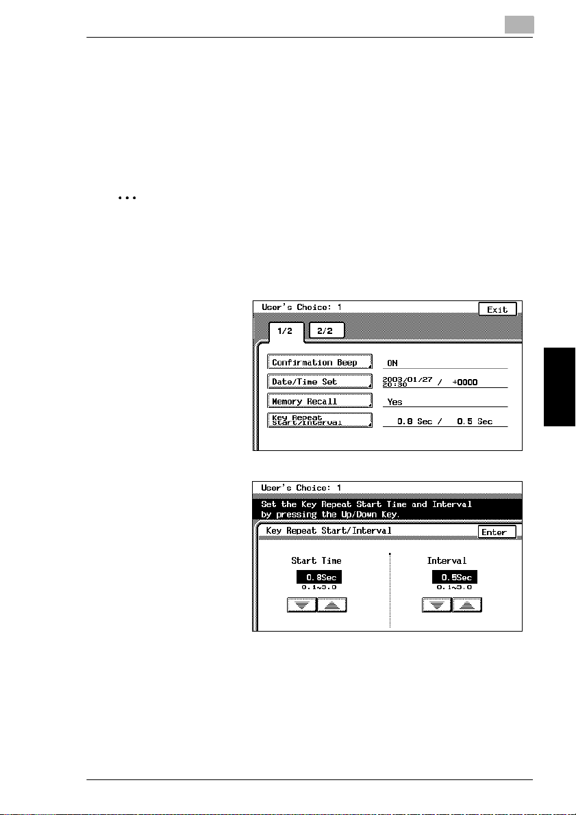
To set the “Key Repeat Start Time/Interval” function
The length of time until the repeat feature for a key starts when a key in the touch
panel is held down can be specified. (The default setting for the start time is 0.8
second and the default setting for the repeat interval is 0.1 second.)
For more details, refer to “Repeat Feature for Keys” in “Before Making Copies” of
the Enlarge Display Operations volume.
5
✎
Note
The settings for the repeat feature are only applied in the Enlarge Display mode;
they are not applied when the screen is displayed normally.
1
Press the [Utility] key.
2
Touch [User’s Choice:
1].
3
Touch [Key Repeat
Start Time/Interval].
4
Touch [▲] and [▼] to
specify the desired
length of time until the
repeat feature for a key
starts (between 0.1 and
3.0 seconds).
5
Touch [Enter].
6
Touch [Fin. Time], and then touch [Fin. Time] again in the screen that appears.
CF2002/CF3102 5-15
Utility Mode Operations Chapter 5
Page 57

5
To set the “Auto Panel Reset” function
This function is used to specify the length of time after the last operation until all
functions automatically return to their default settings. (The default setting is
[1 min.].)
For details on the automatic panel reset, refer to “Original Documents/Feeding the
Document” in the Basic Operations volume.
1
Press the [Utility] key.
2
Touch [User’s Choice: 1].
3
Touch [2/2].
4
Touch [Auto Panel
Reset].
5
Press the [C] (clear)
key. The current setting
is erased.
6
Using the keypad, enter
the desired length of
time (between 1 and 9
minutes).
If you do not wish
❍
for the copier to
automatically reset
its modes and
functions, touch
[No].
5.2 Specifying Default Settings (“User’s Choice” Functions)
Utility Mode Operations Chapter 5
7
Touch [Enter].
8
Touch [Fin. Time], and then touch [Fin. Time] again in the screen that appears.
5-16 CF2002/CF3102
Page 58

5.2 Specifying Default Settings (“User’s Choice” Functions)
To set the “Energy Saver” function
This function is used to specify the length of time after the last operation until the
copier automatically enters Energy Saver mode. (The default setting is [15 min.].)
for entering Energy Saver mode.
For details on the Energy Saver mode, refer to “Original Documents/Feeding the
Document” in the Basic Operations volume.
1
Press the [Utility] key.
2
Touch [User’s Choice: 1].
3
Touch [2/2].
4
Touch [Energy Saver].
5
5
Press the [C] (clear) key.
The current setting is erased.
6
Using the keypad, enter
the desired length of
time (between 10 and
240 minutes).
7
Touch [Enter].
8
Touch [Fin. Time], and
then touch [Fin. Time]
again in the screen that
appears.
CF2002/CF3102 5-17
Utility Mode Operations Chapter 5
Page 59

5
To set the “Sleep” function
This function is used to specify the length of time after the last operation until the
copier automatically enters Sleep mode. The copier only enters Sleep mode if the
“Disable Sleep Mode”
setting is “30 min”.)
For details on the Sleep mode, refer to “Original Documents/Feeding the
Document” in the Basic Operations volume.
1
Press the [Utility] key.
2
Touch [User’s Choice: 1].
3
Touch [2/2].
4
Touch [Sleep].
5.2 Specifying Default Settings (“User’s Choice” Functions)
function of the Administrator mode is set to “No”. (The default
5
Press the [C] (clear) key.
The current setting is erased.
6
Using the keypad, enter
the desired length of
time (between 15 and
240 minutes).
If you do not want
❍
Utility Mode Operations Chapter 5
the copier to enter
Sleep mode, touch
[No].
7
Touch [Enter].
8
Touch [Fin. Time], and then touch [Fin. Time] again in the screen that appears.
5-18 CF2002/CF3102
Page 60
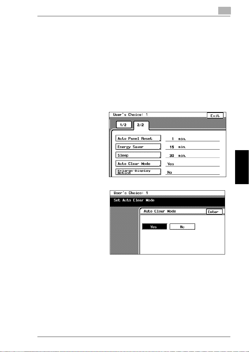
5.2 Specifying Default Settings (“User’s Choice” Functions)
To set the “Auto Clear Mode” function
This function is used to specify whether or not the copier clears all settings when it
detects that the user of the copier has changed, for example, when the magnetic
card has been removed from the optional data controller or when the key counter
has been removed. (The default setting is [Yes].)
For details on clearing all settings when a new user is detected, refer to “Original
Documents/Feeding the Document” in the Basic Operations volume.
1
Press the [Utility] key.
2
Touch [User’s Choice: 1].
3
Touch [2/2].
4
Touch [Auto Clear
Mode].
5
5
Select the desired
setting.
6
Touch [Enter].
7
Touch [Fin. Time], and
then touch [Fin. Time]
again in the screen that
appears.
CF2002/CF3102 5-19
Utility Mode Operations Chapter 5
Page 61
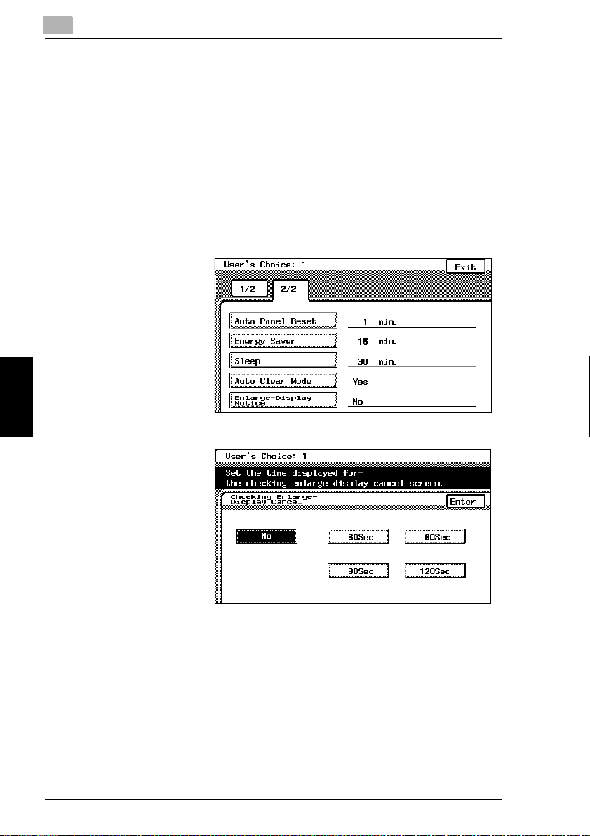
5
To set the “Enlarge-Display Notice” function
If the “Auto Clear Mode” function is set to “Yes”, the message requesting
confirmation to cancel the Enlarge Display mode can be displayed. (The default
setting is “No”.)
In addition, it is possible to specify the length of time that the message requesting
confirmation to cancel the Enlarge Display mode is displayed.
For more details, refer to “Confirming the Cancellation of the Enlarge Display Mode”
in “Before Making Copies” of the Enlarge Display Operations Guide.
1
Press the [Utility] key.
2
Touch [User’s Choice:
1].
3
Touch [2/2].
4
Touch [Enlarge-Display
Notice].
5.2 Specifying Default Settings (“User’s Choice” Functions)
5
Select the desired
setting and specify the
length of time (30, 60,
90 or 120 seconds) that
the message
requesting confirmation
to cancel the Enlarge
Display mode is
displayed.
Utility Mode Operations Chapter 5
6
If you do not wish for the message requesting confirmation to cancel the Enlarge
Display mode to appear, touch [No].
7
Touch [Enter].
8
Touch [Fin. Time], and then touch [Fin. Time] again in the screen that appears.
5-20 CF2002/CF3102
Page 62

5.2 Specifying Default Settings (“User’s Choice” Functions)
5
“Specialty Paper” Settings
This function is used to specify that the paper loaded into any paper drawer is
special paper. (The default setting is [Standard].)
If the drawer is set to “Specialty”, the paper is not automatically selected with Paper
setting “Auto Paper” or with double-sided copying.
To print on special paper, select the paper drawer loaded with special paper.
When printing regardless of the paper type, paper in a drawer set to “Standard” is
selected with Paper setting “Auto Paper”.
When printing regardless of the paper type, paper set to “Standard” is selected with
the automatic selection functions.
Only with special printing is the “Specialty” paper setting selected for making
copies.
“Standard” setting
Select this setting if plain paper is loaded. This is the default setting.
G
Paper with this setting can be automatically selected with the paper setting
G
“Auto Paper” and Zoom setting “Auto Size”.
“High Quality Paper” setting
Select this setting when using High Quality paper.
G
Paper with this setting is not automatically selected with the Paper setting “Auto
G
Paper”.
“Single Sided Only” setting
Select this setting for paper that should not be used with double-sided copying
G
(for example, when one side has already been printed on).
Paper with this setting is not automatically selected during automatic double-
G
sided copying.
“Specialty” setting
Select this setting for paper, other than “High Quality Paper” or “Single Sided
G
Only” paper, that should not be selected automatically.
Paper with this setting is not automatically selected with the Paper setting “Auto
G
Paper”.
CF2002/CF3102 5-21
Utility Mode Operations Chapter 5
Page 63

5
To set the “Specialty Paper” function
1
Press the [Utility] key.
2
Touch [User’s Choice: 2].
3
Touch [Specialty
Paper].
4
Select the paper
drawer that you wish to
set.
5
Select the desired
paper setting.
5.2 Specifying Default Settings (“User’s Choice” Functions)
6
Touch [Enter].
7
Touch [Fin. Time], and
then touch [Fin. Time]
again in the screen that appears.
Utility Mode Operations Chapter 5
5-22 CF2002/CF3102
Page 64

5.2 Specifying Default Settings (“User’s Choice” Functions)
Specifying the Output Tray Priority
The “Priority exit tray” function is used to specify the output tray that is given priority
for each application.
This function can be set only if the finisher (FN-116) is installed.
(The default settings are tray “2” for copying and printing, and tray “3” for Internet
faxing.)
Applications
The applications referred to here are copying, PC printing and Internet fax printing
(Internet faxing).
PC printing and Internet fax printing can only be used if the optional printer
controller is installed.
To set the “Priority exit tray” function
1
Press the [Utility] key.
2
Touch [User’s Choice: 2].
3
Touch [Priority exit
tray].
5
4
Select the output tray
that you wish to assign
to each application.
5
Touch [Enter].
6
Touch [Fin. Time], and
then touch [Fin. Time]
again in the screen that
appears.
CF2002/CF3102 5-23
Utility Mode Operations Chapter 5
Page 65
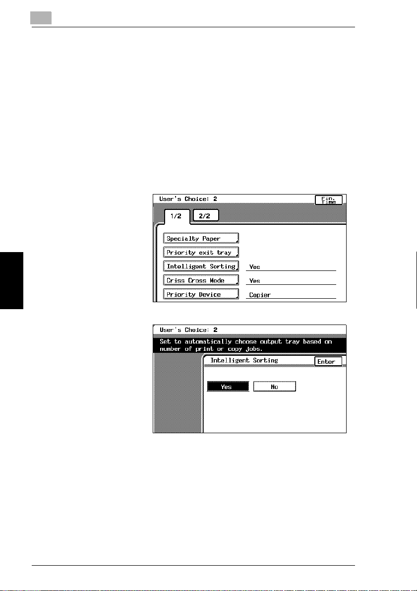
5
To set the “Intelligent Sorting” function
This function is used to specify if the “Sort” setting or the “Non-Sort” setting is
selected automatically for documents loaded into the duplexing document feeder.
By setting this function to “Yes”, the “Non-Sort” setting will automatically be selected
if a document consisting of only one page is loaded into the duplexing document
feeder, and the “Sort” setting will automatically be selected if a document consisting
of two or more pages is placed in the duplexing document feeder. (The default
setting is [Yes].)
1
Press the [Utility] key.
2
Touch [User’s Choice: 2].
3
Touch [Intelligent
Sorting].
5.2 Specifying Default Settings (“User’s Choice” Functions)
4
Select the desired
setting.
5
Touch [Enter].
6
Touch [Fin. Time], and
then touch [Fin. Time]
again in the screen that
appears.
Utility Mode Operations Chapter 5
5-24 CF2002/CF3102
Page 66

5.2 Specifying Default Settings (“User’s Choice” Functions)
To set the “Criss Cross Mode” function
This function is used to specify how copies are sorted when the “Sort” setting is
selected. (The default setting is [Yes].)
For details on crisscross sorting, refer to “Original Documents/Feeding the
Document” in the Basic Operations volume.
1
Press the [Utility] key.
2
Touch [User’s Choice: 2].
3
Touch [Criss Cross
Mode].
4
Select the desired
setting.
5
5
Touch [Enter].
6
Touch [Fin. Time], and
then touch [Fin. Time]
again in the screen that
appears.
CF2002/CF3102 5-25
Utility Mode Operations Chapter 5
Page 67

5
To set the “Priority Device” function
This function is used to specify the print timing for a print job that is received.
Copy jobs and Internet fax print jobs are normally printed as a set. (The default
setting is [Copier].)
Copier setting
Print jobs are queued as a job when the data for all pages are received.
Printer setting
Print jobs are queued as a job when the data for the first page is received.
1
Press the [Utility] key.
2
Touch [User’s Choice: 2].
3
Touch [Priority Device].
5.2 Specifying Default Settings (“User’s Choice” Functions)
4
Select the desired
setting.
5
Touch [Enter].
6
Touch [Fin. Time], and
Utility Mode Operations Chapter 5
then touch [Fin. Time]
again in the screen that
appears.
5-26 CF2002/CF3102
Page 68
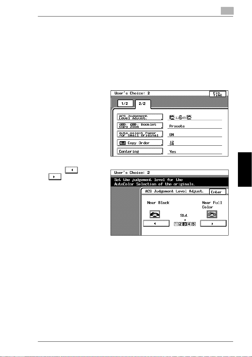
5.2 Specifying Default Settings (“User’s Choice” Functions)
To set the “ACS Judgement Level Adjust.” function
This function is used to adjust the level for detecting a color or black-and -white
document with the Color setting “Auto Color”. The detection level can be adjusted
to one of 5 settings. (The default setting is [3 (Std.)].)
1
Press the [Utility] key.
2
Touch [User’s Choice: 2].
3
Touch [2/2].
4
Touch [ACS
Judgement Level
Adjust.].
5
Touch and
to specify the
desired detection level.
5
6
Touch [Enter].
7
Touch [Fin. Time], and
then touch [Fin. Time]
again in the screen that
appears.
CF2002/CF3102 5-27
Utility Mode Operations Chapter 5
Page 69
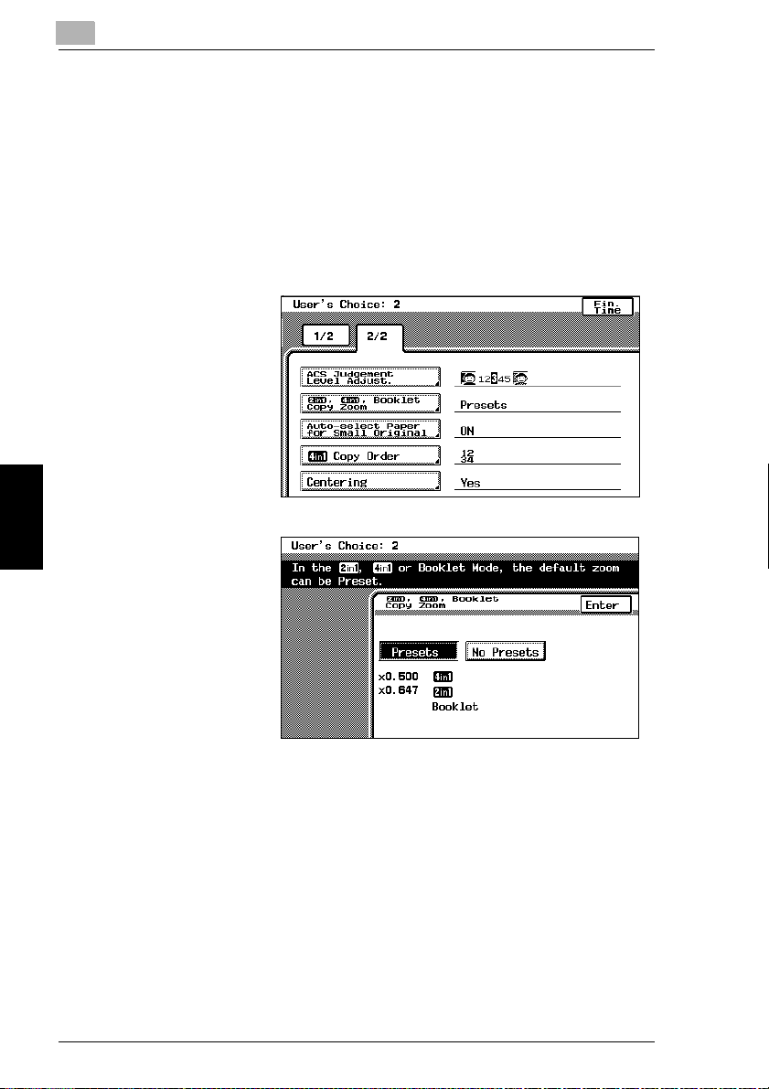
5
To set the “2in1, 4in1, Booklet Copy Zoom” function
This function is used to specify the zoom ratio for 2in1 copying, 4in1 copying and
booklet binding. If this function is set, the specified zoom ratio is automatically
applied when any of these Copy settings are selected. (The default setting is
[Presets].)
1
Press the [Utility] key.
2
Touch [User’s Choice: 2].
3
Touch [2/2].
4
Touch [2in1, 4in1,
Booklet Copy Zoom].
5
Select the desired
setting.
5.2 Specifying Default Settings (“User’s Choice” Functions)
6
Touch [Enter].
7
Touch [Fin. Time], and
then touch [Fin. Time]
again in the screen that
appears.
Utility Mode Operations Chapter 5
5-28 CF2002/CF3102
Page 70

5.2 Specifying Default Settings (“User’s Choice” Functions)
To set the “Auto-select Paper for Small Original” function
This function is used to select whether or not to print documents with a size that is
too small and cannot be automatically detected. (The default settings are “ON” and
the 1st drawer.)
If this function is set to “Off”, copies cannot be made under either of the following
conditions.
When the [Start] key is pressed with the Paper setting “Auto Paper” selected,
✔
but the size of the document is too small to be detected and the paper cannot
be selected
When the [Start] key is pressed with the Paper setting “Auto Paper” selected,
✔
but no document has been loaded
5
✎
Tip
If this function is set to “ON”, copies will be made even under the conditions
described above.
In this case, since the document size cannot be detected and the paper cannot
be automatically selected, the paper (source) must be selected.
1
Press the [Utility] key.
2
Touch [User’s Choice: 2].
3
Touch [2/2].
4
Touch [Auto-select
Paper for Small
Original].
CF2002/CF3102 5-29
Utility Mode Operations Chapter 5
Page 71
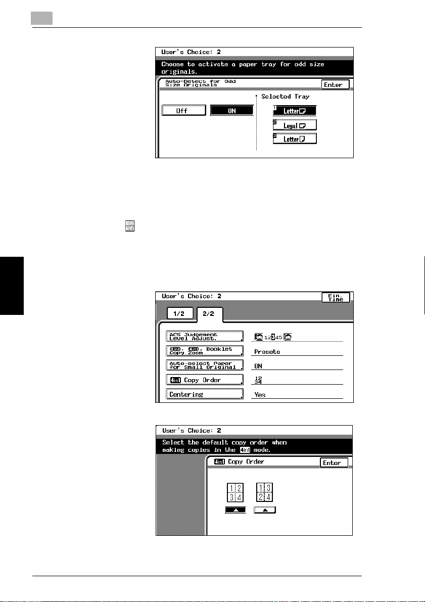
5
5
Select the desired
setting.
6
If “ON” was selected,
select a paper drawer.
7
Touch [Enter].
8
Touch [Fin. Time], and
then touch [Fin. Time]
again in the screen that
appears.
To set the “4in1 Copy Order” function
This function is used to specify the copy order during 4in1 copying.
(The default setting is [ ].)
1
Press the [Utility] key.
2
Touch [User’s Choice: 2].
3
Touch [2/2].
5.2 Specifying Default Settings (“User’s Choice” Functions)
4
Touch [4in1 Copy
Order].
5
Utility Mode Operations Chapter 5
Select the desired
setting.
6
Touch [Enter].
7
Touch [Fin. Time], and
then touch [Fin. Time]
again in the screen that
appears.
5-30 CF2002/CF3102
Page 72

5.2 Specifying Default Settings (“User’s Choice” Functions)
To set the “Centering” function
This function is used to specify the printing position of the image when the
document is smaller than the paper. (The default setting is [Yes].)
1
Press the [Utility] key.
2
Touch [User’s Choice: 2].
3
Touch [2/2].
4
Touch [Centering].
5
Select the desired
setting.
6
Touch [Enter].
5
7
Touch [Fin. Time], and
then touch [Fin. Time]
again in the screen that
appears.
CF2002/CF3102 5-31
Utility Mode Operations Chapter 5
Page 73

5
5.3 Viewing Counters (“Meter Count” Function)
5.3 Viewing Counters (“Meter Count” Function)
The counters, showing the number of the various types of copies that have been
made since the copier was installed, can be viewed.
The following counts can be viewed.
Total counters
Total: Total number of copies and printouts
G
Size: Total number of copies and printouts on paper specified as large-size
G
paper
Duplex Copy: Total number of double-sided copies
G
Duplex Print: Total number of double-sided printouts
G
Scan: Total number of scans
G
Black counters
Copy Total: Total number of black-and-white copies
G
Copy Size: Total number of black-and-white copies on paper specified as large-
G
size paper
Printer Total: Total number of black-and-white printouts
G
Printer Size: Total number of black-and-white printouts on paper specified as
G
large-size paper
Copy+Printer: Total number of black-and-white copies and printouts
G
Full Color counters
Copy Total: Total number of full-color copies
G
Copy Size: Total number of full-color copies on paper specified as large-size
G
paper
Printer Total: Total number of full-color printouts
G
Printer Size: Total number of full-color printouts on paper specified as large-size
G
paper
Copy+Printer: Total number of full-color copies and printouts
G
Mono Color counters
Utility Mode Operations Chapter 5
Copy Total: Total number of monotone copies
G
Copy Size: Total number of monotone copies on paper specified as large-size
G
paper
5-32 CF2002/CF3102
Page 74

5.3 Viewing Counters (“Meter Count” Function)
1
Press the [Utility] key.
2
Touch [Meter Count].
3
Select the desired color
mode. The counters
are displayed.
4
To print the list of
counters, touch [Print],
and then press the
[Start] key.
The list of counters is
printed.
*The lists are only printed in English.
5
Touch [Cancel].
6
Touch [Fin. Time].
5
CF2002/CF3102 5-33
Utility Mode Operations Chapter 5
Page 75

5
5.4 Viewing Part Maintenance Levels (“Unit life indicator” Function)
5.4 Viewing Part Maintenance Levels (“Unit life
indicator” Function)
The level of use for the various supplies and parts can be checked.
1
Press the [Utility] key.
2
Touch [Unit life
indicator].
3
Graphs showing the
maintenance levels for
the various parts and
supplies are displayed.
4
To print the
maintenance levels for
the copier, touch [Print],
and then press the [Start] key.
The list of maintenance levels are printed.
*The list is only printed in English.
5
Touch [Cancel].
6
Touch [Fin. Time].
Utility Mode Operations Chapter 5
5-34 CF2002/CF3102
Page 76
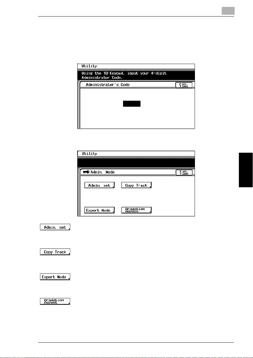
5.5 Administrator Mode Operations
5
5.5 Administrator Mode Operations
The Administrator mode allows the use of the copier to be controlled. When this
mode is selected, a screen appears, indicating that the administrator access code
must be entered.
When the administrator access code is entered, the following screen appears.
(Refer to p. 5-36)
These functions allow you to specify the amount of the top edge of the image
G
that is erased, the Shut off mode, the size of over size paper and the language.
(Refer to p. 5-60)
These functions allow you to restrict the number of copies possible for each
G
account.
(Refer to p. 5-40)
In the Expert mode, you can make various expert adjustments, such as color
G
shift corrections and print area adjustments.
(Refer to p. 5-56)
This function is used to adjust the gradation levels of images.
G
CF2002/CF3102 5-35
Utility Mode Operations Chapter 5
Page 77

5
To set the “Top Erase” function
This function is used to set the amount of loss at the edge of the original. This
amount is erased during printing. (The default setting is [5 mm].)
1
Press the [Utility] key.
2
Touch [Admin. Mode].
3
Using the keypad, enter the administrator access code.
4
Touch [Admin. set].
5
Touch [Top Erase].
6
Select the desired
setting.
5.5 Administrator Mode Operations
7
Touch [Enter].
Utility Mode Operations Chapter 5
8
Touch [Fin. Time] again in the next three screens that appear.
5-36 CF2002/CF3102
Page 78

5.5 Administrator Mode Operations
To set the “Disable Sleep Mode” function
This function is used to disable the Sleep mode. (The default setting is [No].)
Setting this function to “Yes” allows you to disable the Sleep mode completely using
the “Sleep” function available through the User’s Choice: 1 screen.
For details on the Sleep mode, refer to “Original Documents/Feeding the
Document” in the Basic Operations volume.
For more details on setting the “Sleep” function, refer to “Specifying Default Settings
(“User’s Choice” Functions)” (page 5-7).
1
Press the [Utility] key.
2
Touch [Admin. Mode].
3
Using the keypad, enter the administrator access code.
4
Touch [Admin. set].
5
Touch [Disable Sleep
Mode].
5
6
Touch [Yes].
7
Touch [Enter].
8
Touch [Fin. Time] again
in the next three
screens that appear.
CF2002/CF3102 5-37
Utility Mode Operations Chapter 5
Page 79

5
To set the “over size paper selection” function
This function is used to set the paper size for Over sized paper.
(The default setting is [12 × 18].)
1
Press the [Utility] key.
2
Touch [Admin. Mode].
3
Using the keypad, enter the administrator access code.
4
Touch [Admin. set].
5
Touch [over size paper
selection].
5.5 Administrator Mode Operations
6
Select the desired
setting.
7
Touch [Enter].
8
Touch [Fin. Time] again
in the next three
screens that appear.
Utility Mode Operations Chapter 5
5-38 CF2002/CF3102
Page 80
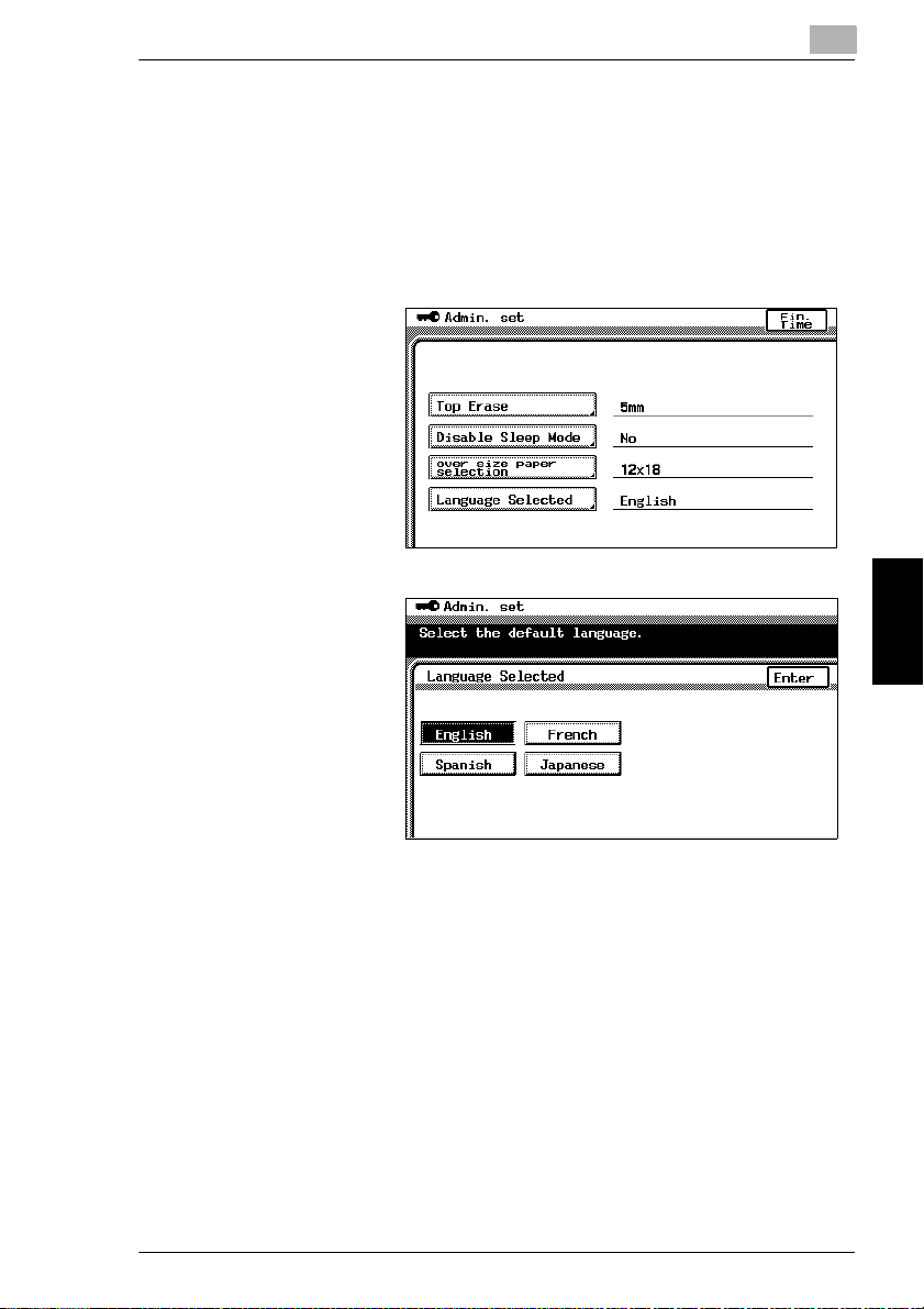
5.5 Administrator Mode Operations
To set the “Language Selected” function
This function is used to change the display language for the touch panel.
(The default setting is [English].)
1
Press the [Utility] key.
2
Touch [Admin. Mode].
3
Using the keypad, enter
the administrator
access code.
4
Touch [Admin. set].
5
Touch [Language
Selected].
6
Select the desired
language.
7
Touch [Enter].
5
8
Touch [Fin. Time], and
then touch [Fin. Time]
again in the screen that
appears.
CF2002/CF3102 5-39
Utility Mode Operations Chapter 5
Page 81

5
5.5 Administrator Mode Operations
Specifying Expert Mode functions
In the Expert mode, various print image adjustments can be selected.
(Refer to p. 5-41)
This function allows the density of the image printed on thick paper to be
G
adjusted.
(Refer to p. 5-42)
These functions are used to make fine adjustments in the color shift of the
G
printed image.
(Refer to p. 5-46)
This function is used to make adjustments to the printed image of black-and-
G
white copies. (This function is only available on the CF2002.)
(Refer to p. 5-47)
This function is used to perform image stabilization.
G
(Refer to p. 5-47)
These functions are used to make fine adjustments to the print area margins of
G
a printed image.
(Refer to p. 5-54)
This function is used to make fine adjustments to the center stapling position
G
Utility Mode Operations Chapter 5
and the folding position when binding.
5-40 CF2002/CF3102
Page 82

5.5 Administrator Mode Operations
To set the “Thick Paper and OHP Film Image Density” function
This function allows the density of the image printed on thick paper and overhead
projector transparencies to be adjusted. (The default settings are [the standard
settings (middle settings)].)
1
Press the [Utility] key.
2
Touch [Admin. Mode].
3
Using the keypad, enter the administrator access code.
4
Touch [Expert Mode].
5
Touch [Thick Paper
and OHP Film Image
Density].
5
6
Touch and
to adjust the image
density.
7
Touch [Enter].
8
Touch [Fin. Time] again
in the next three
screens that appear.
CF2002/CF3102 5-41
Utility Mode Operations Chapter 5
Page 83
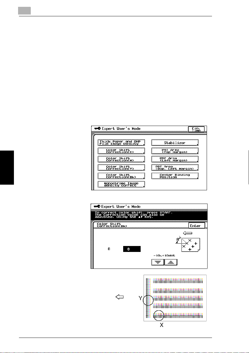
5
To adjust the color shifts manually
If a difference can be seen between the original document and the copy, fine
adjustments in the color shift can be made.
The procedure with 11 × 17-size paper loaded into the 1st drawer is described
below.
1
Load 11 × 17-size paper into the 1st drawer.
2
Press the [Utility] key.
3
Touch [Admin. Mode].
4
Using the keypad, enter the administrator access code.
5
Touch [Expert Mode].
6
Touch [Color Shift
Correction(Bk)].
5.5 Administrator Mode Operations
7
Press the [Start] key.
The automatic color
shift adjustment
procedure begins, and
the test pattern is
printed on the 11 × 17-
size paper.
Utility Mode Operations Chapter 5
Paper feed direction
5-42 CF2002/CF3102
Page 84

5.5 Administrator Mode Operations
A
B
A
B
8
Fold the paper in half while aligning
the corners of the printed test pattern.
9
If horizontal lines A and B are angled
as shown at the right, touch to
specify the desired negative
adjustment for θ (between -1 dot and
-10 dots).
5
A
B
10
If horizontal lines A and B are angled
as shown at the right, touch to
specify the desired positive
adjustment for θ (between +1 dot and
+10 dots).
11
Press the [Start] key.
The adjusted test pattern is printed on 11 × 17-size paper.
CF2002/CF3102 5-43
Utility Mode Operations Chapter 5
Page 85

5
12
Check the print result. If the fold line and the black lines are parallel, skip to step
13.
If more adjustment is necessary, return to step 7 and repeat the adjustment
❍
procedure.
13
Touch [Enter]. The Expert User’s Mode screen appears again.
14
Touch [Color Shift Correction(C)].
15
Press the [Start] key.
The automatic color shift adjustment procedure begins, and the test pattern is
printed on the 11 × 17-size paper.
16
Check the distance from the reference line of the black lines to the cyan lines in
the test pattern along the X and Y directions.
If there is no shift in the reference line, skip to step 23.
❍
17
If the lines are shifted as shown at the
right, touch to specify the
desired negative adjustment for “X”
(between -1 dot and -6 dots).
5.5 Administrator Mode Operations
18
If the lines are shifted as shown at the
right, touch to specify the
Utility Mode Operations Chapter 5
desired positive adjustment for “X”
(between +1 dot and +6 dots).
5-44 CF2002/CF3102
Page 86
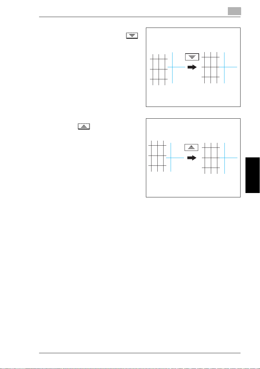
5.5 Administrator Mode Operations
19
If the lines are shifted as shown at the
right, touch [Y], and then touch
to specify the desired negative
adjustment for “Y” (between -1 dot and
-6 dots).
20
If the lines are shifted as shown at the
right, touch to specify the
desired positive adjustment for “Y”
(between +1 dot and +6 dots).
5
21
Press the [Start] key. The adjusted test pattern is printed on 11 × 17-size paper.
22
Check the print result. If the distance between the reference line of the black
lines and the cyan lines is adjusted to 0, skip to step 23.
If more adjustment is necessary, return to step 14 and repeat the adjustment
❍
procedure.
23
Touch [Enter]. The Expert User’s Mode screen appears again.
24
Touch [Color Shift Correction(M)]. Repeat the procedure for adjusting the cyan
shift (steps 13 to 23) to adjust the magenta shift.
25
Touch [Color Shift Correction(Y)] and repeat the same procedure for the yellow
shift.
26
Touch [Enter].
The Expert User’s Mode screen appears again.
27
Touch [Fin. Time] again in the next three screens that appear.
CF2002/CF3102 5-45
Utility Mode Operations Chapter 5
Page 87

5
To set the “Monochrome Image density correct” function
This function allows the image density of black-and-white copies to be adjusted.
(This function is only available on the CF2002.)
(The default setting is [the standard setting (middle setting)].)
1
Press the [Utility] key.
2
Touch [Admin. Mode].
3
Using the keypad, enter the administrator access code.
4
Touch [Expert Mode].
5
Touch [Monochrome
Image density correct].
5.5 Administrator Mode Operations
6
Touch and
to adjust the image
density.
7
Touch [Enter].
8
Touch [Fin. Time] in the
next three screens that
appear.
Utility Mode Operations Chapter 5
5-46 CF2002/CF3102
Page 88

5.5 Administrator Mode Operations
To set the “Stabilizer” function
If the image is incorrect, even after the gradation levels have been adjusted, set the
“Stabilizer” function, available on the Admin. Mode screen.
For details on adjusting the gradation levels, refer to “To set the “Gradation Adjust”
function” (p. 5-56).
Setting the “PRT Area” Functions
This function is used to adjust the image print position from the edge of the paper.
There are three “PRT Area” margin functions:
(Refer to p. 5-47)
This function adjusts the starting print position at the leading edge of the paper
G
(with regard to the paper feed direction).
(Refer to p. 5-50)
This function adjusts the starting print position (with regard to the paper feed
G
direction) from the left edge of the paper.
(Refer to p. 5-52)
This function adjusts the starting print position at the left edge of the paper for
G
the second side of a double-sided copy.
To set the “PRT Area (Top Margin)” function
The top margin of the printing area can be adjusted for each paper type.
The procedure described below is for 11” × 17” paper.
5
✎
Note
The top margin of the print area is adjusted during manufacturing of the copier.
Normally, the top margin will not need to be adjusted.
CF2002/CF3102 5-47
Utility Mode Operations Chapter 5
Page 89

5
1
Load 11 × 17-size paper of the desired type into the 1st drawer.
2
Turn the media type selection dial to
the setting for the type of paper
loaded.
5.5 Administrator Mode Operations
Envelope
OHP
Plain
Plain
3
Press the [Utility] key.
4
Touch [Admin. Mode].
5
Using the keypad, enter the
administrator access code.
6
Touch [Expert Mode].
7
Touch [PRT Area (Top
Margin)].
8
Press the [Start] key.
The test pattern is
printed on the 11 × 17-
size paper.
Thick3
Thick3
Thick1
Thick1
Thick2
Thick2
Utility Mode Operations Chapter 5
5-48 CF2002/CF3102
Page 90

5.5 Administrator Mode Operations
9
Check that the top
margin of the test
pattern is between
4.5 mm and 5.5 mm. If
the top margin is within
the specified range,
skip to step 14.
10
If the top margin is less than 4.5 mm, touch to specify the desired positive
adjustment (between +0.1 mm and +3.0 mm).
11
If the top margin is more than 5.5 mm, touch to specify the desired
negative adjustment (between -0.1 mm and -3.0 mm).
12
Press the [Start] key. The adjusted test pattern is printed on 11 × 17-size paper.
13
Check the print result to make sure that the top margin is adjusted to between
4.5 mm and 5.5 mm.
If more adjustment is necessary, return to step 8 and repeat the adjustment
❍
procedure.
a
a: 5.0 mm ± 0.5 mm
5
14
Touch [Enter].
15
Touch [Fin. Time] again in the next three screens that appear.
CF2002/CF3102 5-49
Utility Mode Operations Chapter 5
Page 91

5
To set the “PRT Area (Left Margin)” function
The left margin of the printing area can be adjusted for each paper drawer.
The procedure with 11 × 17-size paper loaded into the 1st drawer is described
below.
5.5 Administrator Mode Operations
✎
Note
The top margin of the print area is adjusted during manufacturing of the copier.
Normally, the top margin will not need to be adjusted.
1
Load 11 × 17-size paper into the 1st drawer.
2
Press the [Utility] key.
3
Touch [Admin. Mode].
4
Using the keypad, enter the administrator access code.
5
Touch [Expert Mode].
6
Touch [PRT Area (Left
Margin)].
7
Touch [1st Drawer].
Utility Mode Operations Chapter 5
8
Press the [Start] key.
The test pattern is
printed on the 11 × 17-
size paper.
5-50 CF2002/CF3102
Page 92
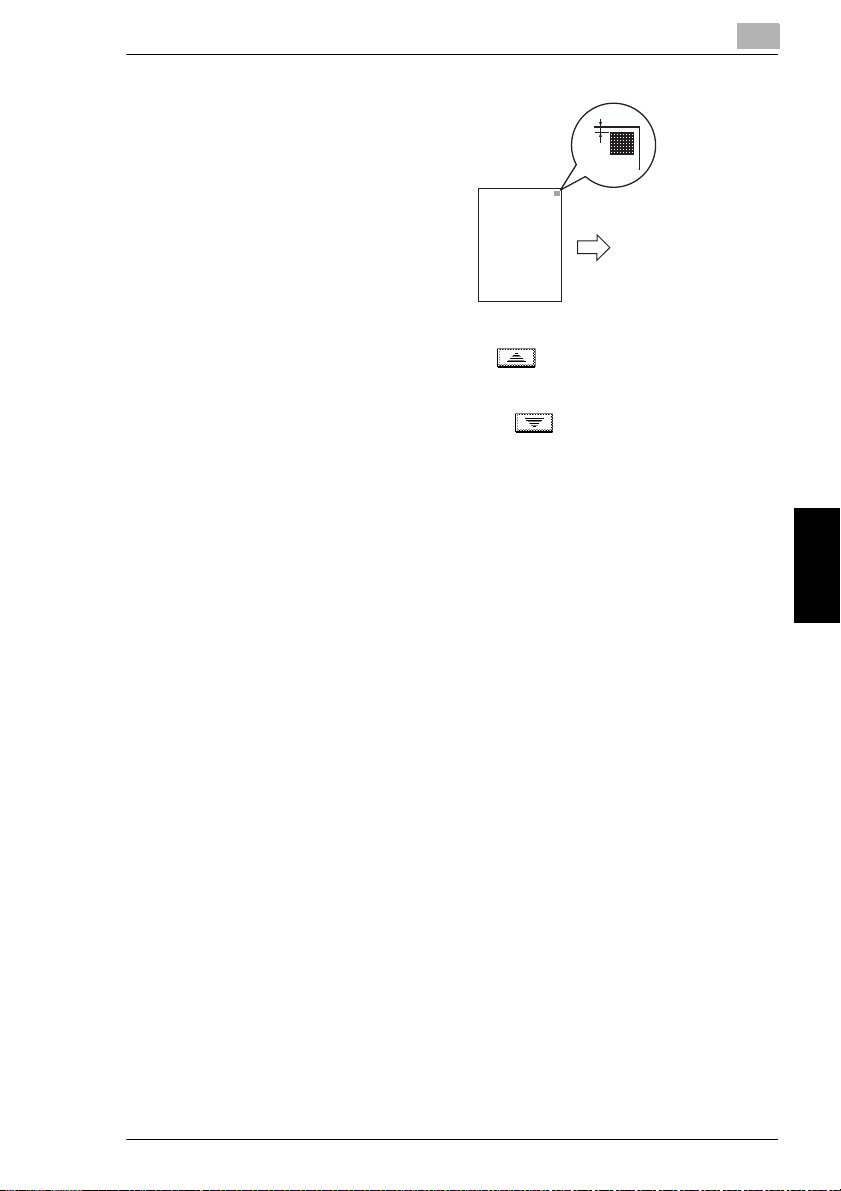
5.5 Administrator Mode Operations
9
Check that the left
margin of the test
pattern is between
2.5 mm and 3.5 mm. If
the left margin is within
the specified range,
skip to step 14.
10
If the left margin is less than 2.5 mm, touch to specify the desired positive
adjustment (between +0.1 mm and +3.0 mm).
11
If the left margin is more than 3.5 mm, touch to specify the desired
negative adjustment (between -0.1 mm and -3.0 mm).
12
Press the [Start] key. The adjusted test pattern is printed on 11 × 17-size paper.
13
Check the print result to make sure that the left margin is adjusted to between
2.5 mm and 3.5 mm.
If more adjustment is necessary, return to step 8 and repeat the adjustment
❍
procedure.
b
b: 3.0 mm ± 0.5 mm
5
14
Touch [Enter].
15
Touch [Fin. Time] again in the next three screens that appear.
CF2002/CF3102 5-51
Utility Mode Operations Chapter 5
Page 93

5
To set the “PRT Area (Dup. Left Margin)” function
The left margin of the printing area in double-sided copies can be adjusted for each
paper drawer.
The procedure with 11 × 17-size paper loaded into the 1st drawer is described
below.
5.5 Administrator Mode Operations
✎
Note
The top margin of the print area is adjusted during manufacturing of the copier.
Normally, the top margin will not need to be adjusted.
1
Load 11 × 17-size paper into the 1st drawer.
2
Press the [Utility] key.
3
Touch [Admin. Mode].
4
Using the keypad, enter the administrator access code.
5
Touch [Expert Mode].
6
Touch [PRT Area (Dup.
Left Margin)].
7
Touch [1st Drawer].
8
Utility Mode Operations Chapter 5
Press the [Start] key.
The test pattern is
printed on 11 × 17-size
paper.
5-52 CF2002/CF3102
Page 94

5.5 Administrator Mode Operations
9
Check that the left
margin of the test
pattern for the second
side is between 2.5 mm
and 3.5 mm.
If the left margin for the
second side is within
the specified range,
skip to step 14.
10
If the left margin for the second side is less than 2.5 mm, touch to specify
the desired positive adjustment (between +0.1 mm and +3.0 mm).
11
If the left margin for the second side is more than 3.5 mm, touch to specify
the desired negative adjustment (between -0.1 mm and -3.0 mm).
12
Press the [Start] key.
The adjusted test pattern is printed on 11 × 17-size paper.
13
Check the print result to make sure that the left margin for the second side is
adjusted to between 2.5 mm and 3.5 mm.
If more adjustment is necessary, return to step 8 and repeat the adjustment
❍
procedure.
c
c: 3.0 mm ± 0.5 mm
5
14
Touch [Enter].
15
Touch [Fin. Time] again in the next three screens that appear.
CF2002/CF3102 5-53
Utility Mode Operations Chapter 5
Page 95

5
To set the “Center Binding Position” function
This function is used to make fine adjustments to the center stapling position and
the folding position when binding. (The default setting is [0 mm].)
Use the “Booklet Creation” setting to make a copy sample.
For details on booklet-binding, refer to “Original Documents/Feeding the
Document” in the Basic Operations volume.
1
Press the [Utility] key.
2
Touch [Admin. Mode].
3
Using the keypad, enter the administrator access code.
4
Touch [Expert Mode].
5
Touch [Center Binding
Position].
5.5 Administrator Mode Operations
6
Compare the width of
the left pages of the
copy sample with the
width of the right pages.
Utility Mode Operations Chapter 5
7
If the staple position is
too far to the left of the
center of the paper,
touch to specify
the desired positive
adjustment (between
+1 mm and +7 mm).
5-54 CF2002/CF3102
Page 96
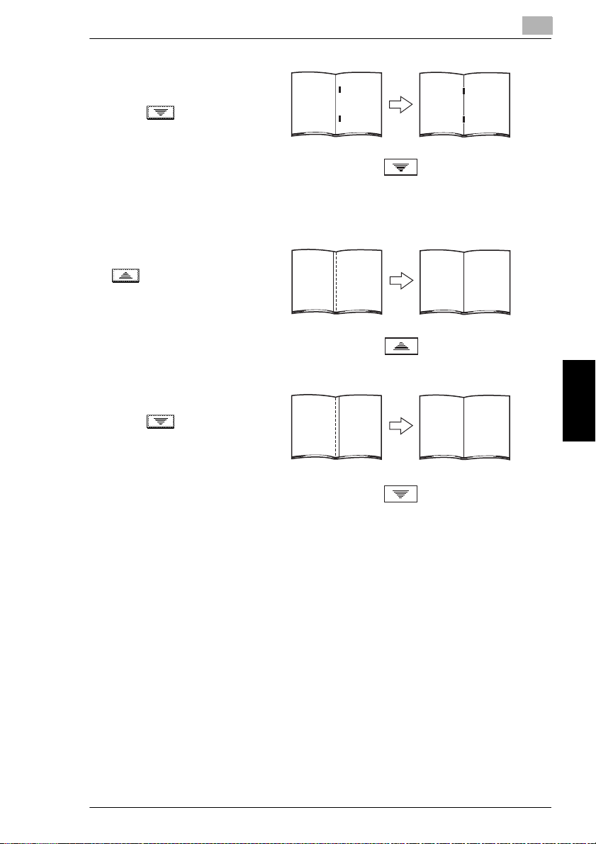
5.5 Administrator Mode Operations
8
If the staple position is
too far to the right of the
center of the paper,
touch to specify
the desired negative
adjustment (between
-1 mm and -7 mm).
9
Touch [Folding Position].
10
If the folding position is
shifted to the left, touch
to specify the
desired positive
adjustment (between
+1 mm and +7 mm).
11
If the folding position is
shifted to the right,
touch to specify
the desired negative
adjustment (between
-1 mm and -7 mm).
5
12
Touch [Enter].
13
Touch [Fin. Time] in the next three screens that appear.
14
Use the “Booklet Creation” setting to make another copy sample.
15
Check the print result.
If more adjustment is necessary, return to step 1 and repeat the adjustment
❍
procedure.
CF2002/CF3102 5-55
Utility Mode Operations Chapter 5
Page 97

5
To set the “Gradation Adjust” function
The color gradation levels can be adjusted if they are incorrect.
After replacing the Imaging Unit, be sure to perform the “Gradation Adjust”,
following the procedures below.
1
Load 11 × 17-size paper into the 1st drawer.
A4 C, A3 or Letter C can be loaded instead.
❍
2
Press the [Utility] key.
3
Touch [Admin. Mode].
4
Using the keypad, enter the administrator access code.
5
Touch [Gradation
Adjust]. The Gradation
Adjust screen appears.
6
Press the [Start] key.
A test pattern is printed.
5.5 Administrator Mode Operations
Utility Mode Operations Chapter 5
7
After the test pattern is
printed, the screen
changes, as shown at
the right.
8
Place the printed test
pattern on the original
glass with the edge with
the printed crop marks
aligned along the
document scale.
5-56 CF2002/CF3102
Page 98

5.5 Administrator Mode Operations
9
Place 10 more sheets of blank paper of the same size on top of the printed test
pattern page.
10
Close the original cover, or the duplexing document feeder if it is installed.
11
Press the [Start] key.
The printed test pattern is scanned.
12
Based on the scanned image, the gradation levels are automatically adjusted.
After the gradation levels are adjusted, the Admin. Mode screen appears again.
13
Repeat steps 5 through 12 three times.
14
Touch [Fin. Time], and then touch [Fin. Time] again in the screen that appears.
5
CF2002/CF3102 5-57
Utility Mode Operations Chapter 5
Page 99
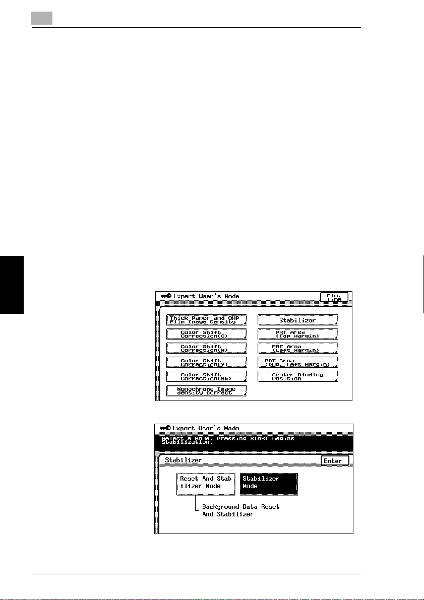
5
To set the “Stabilizer” function (if the image is still incorrect, even after the
gradation levels have been adjusted)
If the image is incorrect, even after the gradation levels have been adjusted, set the
“Stabilizer” function.
The following two modes are available with the “Stabilizer” function.
Reset And Stabilizer Mode
G
Stabilizer Mode
G
The “Stabilizer” function performs an image stabilization based on past data up to
the previous session.
Image stabilization should normally be performed with “Stabilizer Mode” selected.
Select “Reset And Stabilizer Mode” only if the desired effect cannot be attained with
the “Stabilizer Mode”.
1
Press the [Utility] key.
2
Touch [Admin. Mode].
3
Using the keypad, enter the administrator access code.
4
Touch [Expert Mode].
5.5 Administrator Mode Operations
5
Touch [Stabilizer].
6
Utility Mode Operations Chapter 5
Press the [Start] key.
The indicator on the
[Start] key changes to
orange, and the image
stabilization operation
is performed.
The indicator on the
[Start] key changes
back to green.
The image stabilization
procedure is finished.
5-58 CF2002/CF3102
Page 100

5.5 Administrator Mode Operations
7
Touch [Enter].
8
Touch [Fin. Time] again in the next three screens that appear.
5
CF2002/CF3102 5-59
Utility Mode Operations Chapter 5
 Loading...