

Page 1
FrameMaker Ver.5.5(PC) AFR-14 OPTION FOR Di350
98.10.09
AFR-14
SERVICE MANUAL
14413
Page 2

FrameMaker Ver.5.5(PC) AFR-14 OPTION FOR Di350
98.10.09
CONTENTS
GENERAL, MECHANICAL/ELECTRICAL
1. SPECIFICATIONS ........................................................................................... M-1
2. COMPONENT IDENTIFICATION ................... ........................... ............... .......M-3
3. CROSS-SECTIONAL VIEW ............................................................................M-4
4. DRIVE SYSTEM ..............................................................................................M-5
5. ELECTRICAL COMPONENT LAYOUT ...........................................................M-6
6. DESCRIPTION OF MODES ............................................ .............. ..................M-7
6-1. Mixed Original Mode ................................................................................M-7
6-2. 1-Sided Mode ..........................................................................................M-7
6-3. 2-Sided Mode ..........................................................................................M-7
6-4. Single Feed Mode .................... ............... .................................................M-7
7. DOCUMENT TAKE-UP/FEEDING MECHANISM ............................................M-8
7-1. Parts Identification ...................................................................................M-8
7-2. Document Pick-Up Mechanism ...............................................................M-9
7-3. Document Take-Up Mechanism ..............................................................M-11
8. DOCUMENT TRANSPORT MECHANISM ......................................................M-13
8-1. Parts Identification ...................................................................................M-13
8-2. Document Transport Mechanism .............................................................M-14
9. TURNOVER/EXIT MECHANISM ..................................................................... M-15
9-1. Parts Identification ...................................................................................M-15
9-2. Document Transport Mechanism .............................................................M-15
9-3. Turnover/Exit Switching Mechanism ........................................................M-17
10. MISCELLANEOUS ..........................................................................................M-18
10-1.Document Size Detection Mechanism .....................................................M-18
10-2.15° Open Detection Mechanism ........................................ ......................M-18
10-3.Raised/Lowered Position Detection Mechanism .....................................M-18
TEST MODES
1. OUTLINE OF THE TEST MODES ................................................................... S-1
1-1. Test Mode Setting Procedure ..................................................................S-1
1-2. Types of Test Modes ...............................................................................S-1
2. PAPER PASSAGE CHECK .............................................................................S-2
2-1. Paper Passage Modes ............................................................................ S-2
2-2. Paper Passage Check Procedure ...........................................................S-2
3. UNIT CHECK ......................... ...................................................... ............... .....S-3
3-1. Unit Check Modes ............... ............... .....................................................S-3
3-2. Unit Check Procedure ....................................... ................. ......................S-3
4. SENSOR CHECK .................... ........................... ............... ........................... ...S-6
4-1. Sensor Check Mode ........ ............... .........................................................S-6
4-2. Sensor Check Procedure ....................................... ............................... ...S-7
5. BOARD CHECK ..............................................................................................S-8
5-1. Board Check Mode ..................................................................................S-8
5-2. Board Check Procedure ..........................................................................S-8
i
Page 3

FrameMaker Ver.5.5(PC) AFR-14 OPTION FOR Di350
98.10.09
DIS/REASSEMBLY, ADJUSTMENT
1. DISASSEMBLY ...............................................................................................D-1
1-1. Removal of the Transport Belt .................................................................D-1
1-2. Removal of the Pick-Up Rolls, Take-Up Rolls, and Separator Pads .......D-2
2. ADJUSTMENTS ..............................................................................................D-4
2-1. Adjustment of Skew in the ADF ...................... .........................................D-4
2-2. Adjustment of the Document Feed Tray Reference Position ...................D-5
2-3. Adjustment of the Single Feed Tray Reference Position .........................D-6
2-4. Adjustment of the Document Stop Position in the 1-Sided and 1-Sided
Mixed Original Mode ................................................................................D-7
2-5. Adjustment of the Document Stop Position in the 2-Sided Mode ............D-8
2-6. Adjustment of the Document Stop Position in the Single Feed Mode .....D-9
2-7. Adjustment of Turnover/Exit Switching Solenoid SL1 ..............................D-10
TROUBLESHOOTING
1. MISFEED DETECTION ............................................ ............... ........................T-1
2. MISFEED TROUBLESHOOTING PROCEDURES .................................. .......T-3
ii
Page 4

FrameMaker Ver.5.5(PC) AFR-14 OPTION FOR Di350
98.10.09
GENERAL,
MECHANICAL/ELECTRICAL
Page 5
FrameMaker Ver.5.5(PC) AFR-14 OPTION FOR Di350
98.10.09
1 SPECIFICATIONS
Name : Duplexing Document Feeder
Type : Paper Take-Up : Take-up from top of stack, U-turn feeding
Installation : Mounted on the copier
Type of Document : Plain paper : 1-Sided mode - 50 g/m² to 110 g/m²
Detectable Document
Sizes
Capacity : Document Feed Table: 50 sheets (80 g/m²)
Alignment : Rear Document Edge Guide
Document Loading : Face up
Modes : Mixed Original
Power Source : DC24V (supplied from the copier)
Power Consumption : 60W or less
Dimensions : Width 603 mm
Weight : 12.0 kg
Operating Environment : Same as copier
Originals Which Should
Not be Used
Transport : Single-belt transport
Turnover : Loop turnover
Ejection : Straight ejection
2-Sided mode - 60 g/m² to 90 g/m²
Single Feed mode - 35 g/m² to 200 g/m²
: A5L/C, B5C/L, A4C/L, B4L, A3L, 11” × 17”L, 11” × 15”,
8-1/2” × 14”L, 8-1/2” × 11”L/C, 8-1/4” × 13”L
Document Exit Tray: 50 sheets (80 g/m²)
1-Sided
2-Sided
Single Feed
Height 110 mm
Depth 502 mm (excluding Document Exit Tray)
: The following types of originals, if used with the ADF, are
very likely to cause trouble.
Type of Original Possible Trouble
Sheets stapled or clipped together Take-up failure, damaged sheet, defective
Sheets glued together Take-up failure, damaged sheet
Sheets folded, torn, or wrinkled Take-up failure, damaged sheet
Sheets severely curled Sheets mis-fed due to being dog-eared or
Sheets weighing less than 40 g/m² Damaged sheet
drive mechanism due to jammed staples or
clips.
fed in askew
M-1
Page 6
FrameMaker Ver.5.5(PC) AFR-14 OPTION FOR Di350
98.10.09
Originals for Which Feeding is not Guaranteed
Type of Original Possible Trouble
Pieces of paper pasted up on a sheet Folded or torn pasted-up pieces
Slightly curled sheets (curl 10 to 15 mm) Dog-eared pages, ejection failure
Heat-sensitive paper Folded leading edge, ejection failure, trans-
Coated sheets Take-up failure, transport failure
Translucent paper Take-up failure, transport failure
Sheets just fed out of the copier Take-up failure, transport failure
Perf orated sheets (loose-leaf, etc.) Multiple feed due to burrs in perforations
Sheets weighing 40 g/m² to 50 g/m² Folded leading edge
Sheets with surface irregularities
(letterhead, etc.)
Pencil-written sheets Dirty originals
Folded sheets Distorted image, multiple feed, take-up
Sheets of a size outside the range detectable by the ADF
: The following types of originals, if used with the ADF, may
or may not cause trouble.
port failure
Take-up failure
failure
Void image
M-2
Page 7
FrameMaker Ver.5.5(PC) AFR-14 OPTION FOR Di350
98.10.09
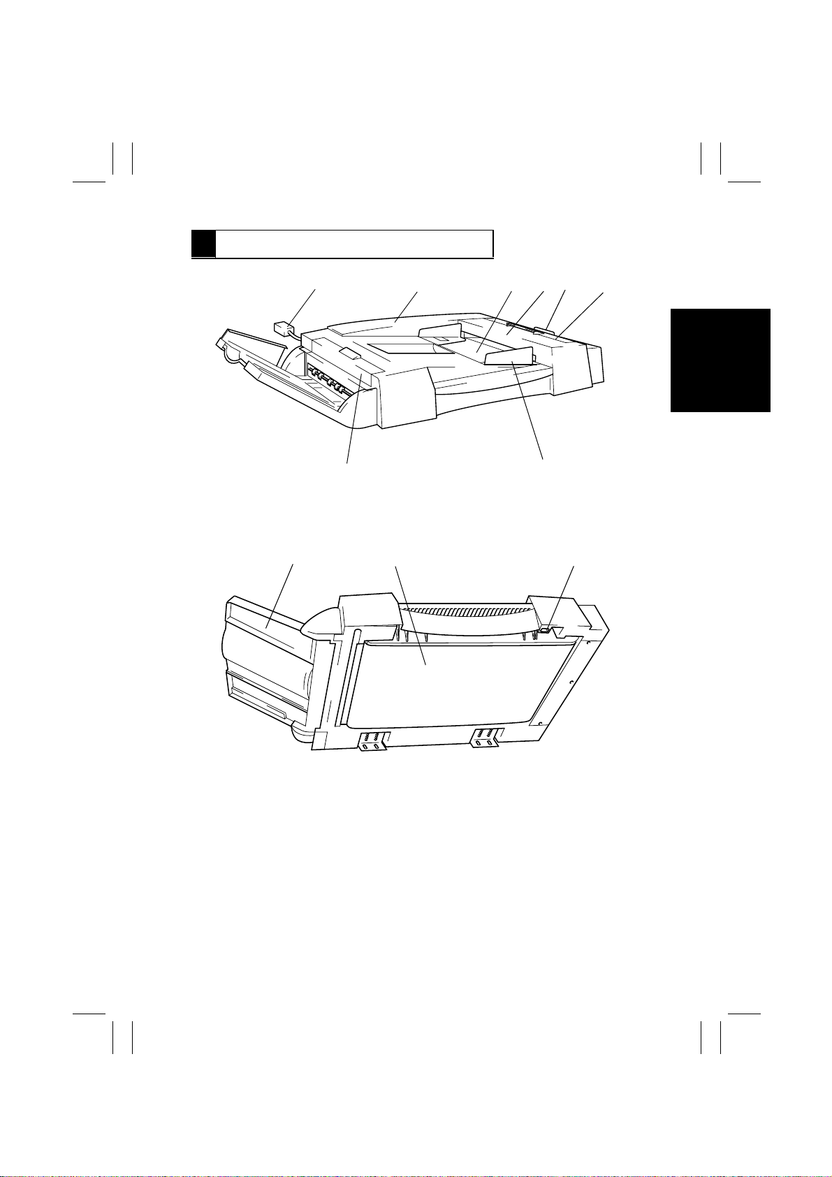
2 COMPONENT IDENTIFICATION
12
8
9
10
3
4
5
6
7
4490M001AA
11
1. Hookup Cord
2. Rear Cover
3. Document Feed Tray
4. Upper Cover
5. Single Feed Tray
6. Take-Up Cover
4490M002AA
7. Document Edge Guide
8. Turnover/Exit Cover
9. Document Exit Tray
10. Transport Belt
11. Magnet
M-3
Page 8
FrameMaker Ver.5.5(PC) AFR-14 OPTION FOR Di350
98.10.09
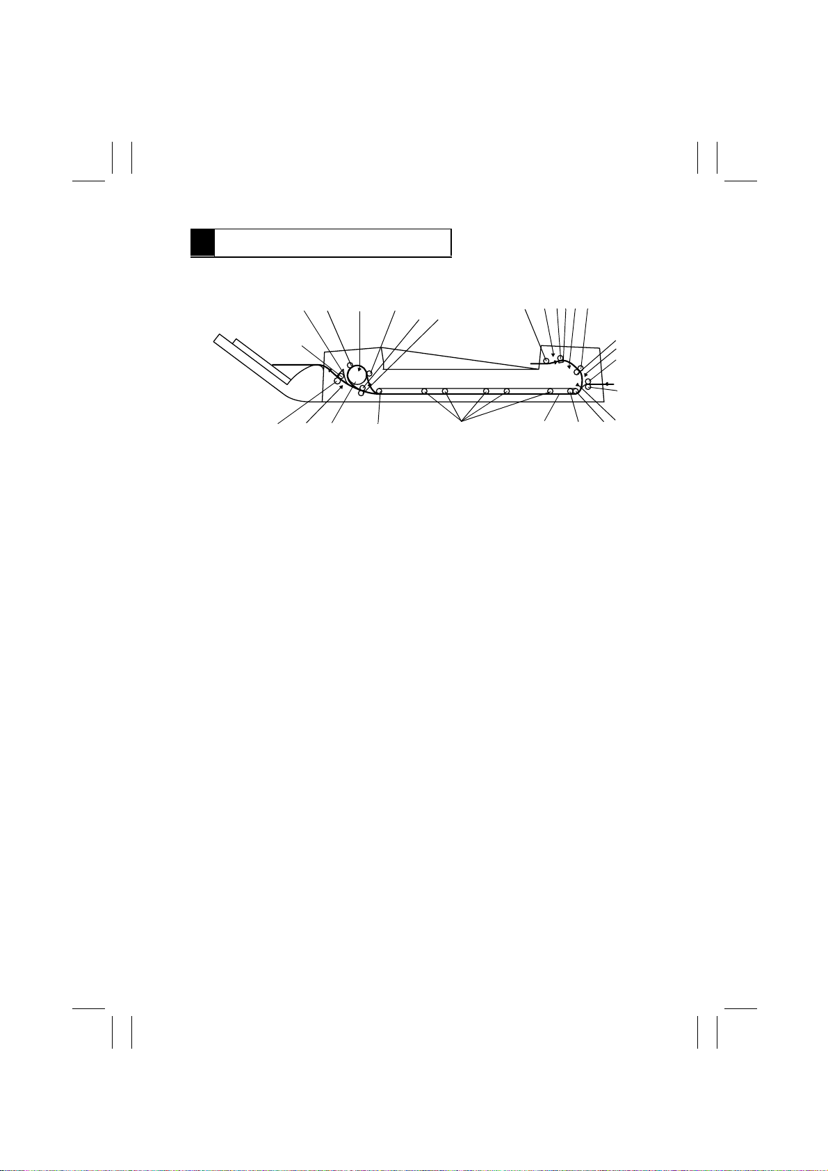
3 CROSS-SECTIONAL VIEW
21
22
23
24
25
26
23456
1
20
17
18
19
1. Pick-Up Roll
2. Empty Sensor PC1
3. Take-Up Roll
4. Separator Pad
5. Registration Sensor PC2
6. Registration Driven Roller
7. Registration Drive Roller
8. Single Feed Empty Sensor PC9
9. Single Feed Roller
10. Single Feed Roll
11. Width Sensor 1/2/3 PC5/6/7
12. Transport Belt Drive Roller
13. Transport Belt Driven Roller
16
15
14. Transport Belt
15. Transport Rolls
16. Transport Belt Driven Roller
17. Turnover Roller
18. Exit Sensor PC3
19. Exit Roller
20. Exit Roll
21. Turnover/Exit Switching Plate
22. Turnover Roll
23. Turnover Sensor PC4
24. Turnover Roll
25. Transport Roller
26. Transport Roll
1314
4490M003AC
12
11
7
8
9
10
M-4
Page 9
FrameMaker Ver.5.5(PC) AFR-14 OPTION FOR Di350
98.10.09
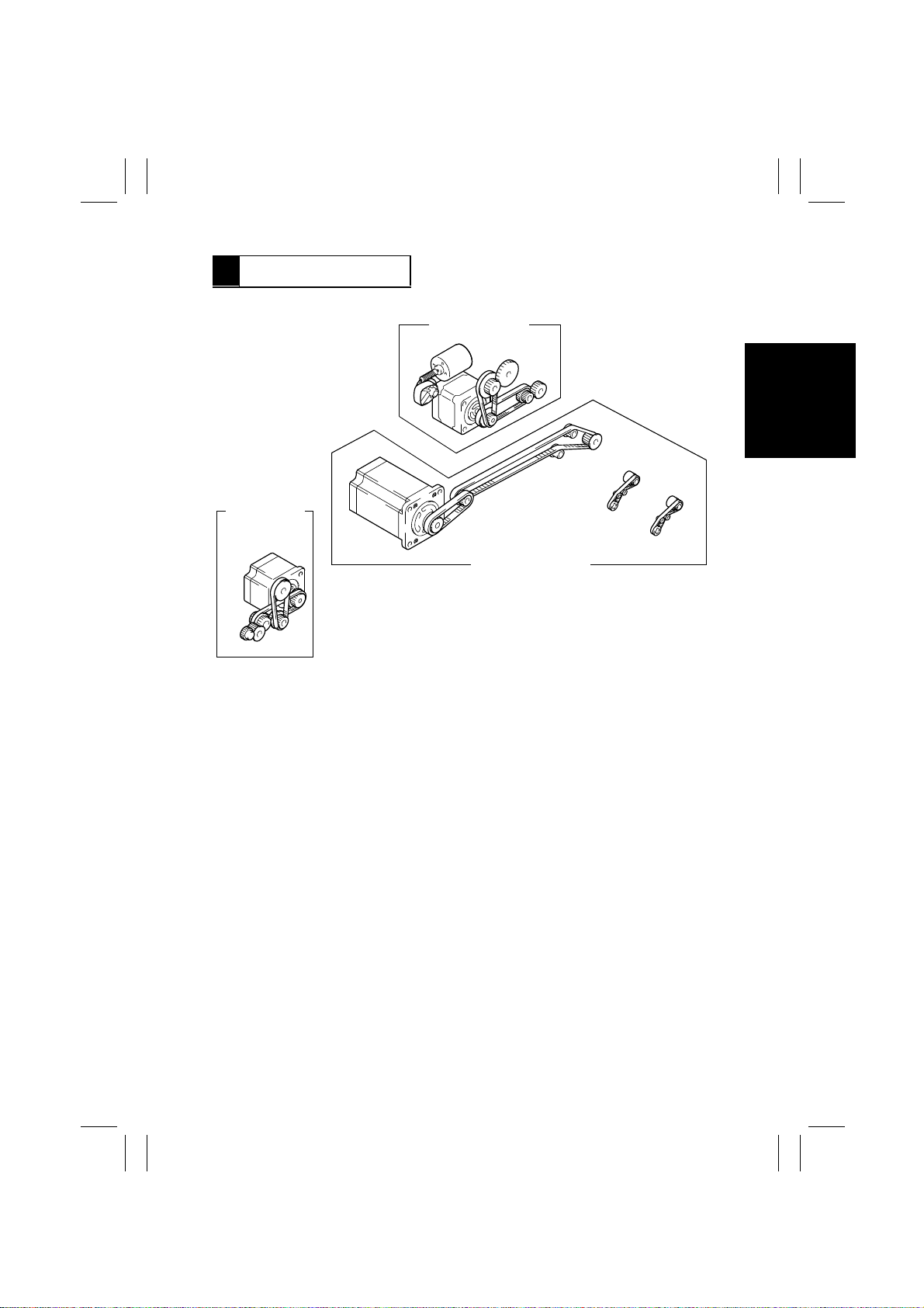
4 DRIVE SYSTEM
Document
Take-Up/Feeding
Turnover/Exit
Document Transport
M-5
4490M004AB
Page 10
FrameMaker Ver.5.5(PC) AFR-14 OPTION FOR Di350
98.10.09
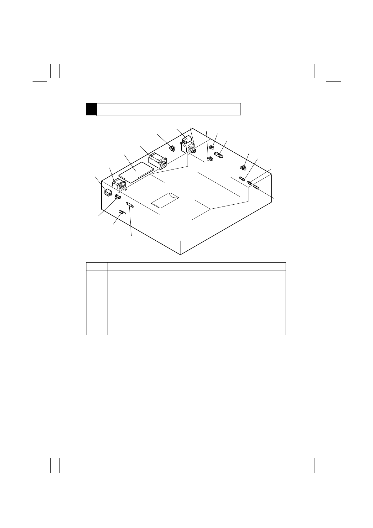
5 ELECTRICAL COMPONENT LAYOUT
M2
PC8
M1
M3
PWB-A
M4
SL1
PC11
PC3
PC4
PC1
PC9
PC2
PC10
PC5
PC6
PC7
4490M005AB
Code Name Code Name
PWB-A
M1
M2
M3
M4
SL1
PC1
PC2
PC3
PC4
Main Control Board
Pick-Up Motor
Take-Up Motor
Main Drive Motor
Turnover/Exit Motor
Turnover/Exit Switching Solenoid
Empty Sensor
Registration Sensor
Exit Sensor
Turnover Sensor
PC5
PC6
PC7
PC8
PC9
PC10
PC11
Width Sensor 1
Width Sensor 2
Width Sensor 3
Pick-Up Sensor
Single Feed Empty Sensor
Take-Up Cover Open/Close
Detecting Sensor
Turnover/Exit Cover Open/Close
Detecting Sensor
M-6
Page 11

FrameMaker Ver.5.5(PC) AFR-14 OPTION FOR Di350
98.10.09
6 DESCRIPTION OF MODES
6-1. Mixed Original Mode
•
The copier detects the size of each page of the document as it is taken up and fed in and,
according to the size detected, feeds the copy paper of the corresponding size selected
from among the available paper sources.
•
The mode is mainly used when making copies from a document set consisting of pages
of different sizes.
6-2. 1-Sided Mode
•
When a multi-page document is being copied, the copier detects the size of only the first
page of the document and copies the subsequent pages based on that size detection.
•
This saves the copier the time required f or detecti ng the sizes of the subsequent pages of
the document, making for a faster and more efficient paper feed timing.
Note:
If a document of pages of varying sizes is used in this mode, image trouble could result
including missing copy image. (The system does not, however, force a misfeed condition.)
6-3. 2-Sided Mode
•
The copier automatically turns over 2-sided originals for a speedy copying operation
(copies are made in the order of the first and second pages).
6-4. Single Feed Mode
•
This mode may be used when the user wants to make copies from an original for which
feeding is not guaranteed (pasted-up sheet, translucent paper, heat-sensitive paper,
etc.).
•
When a single original is inserted into the Single Feed Tray, the ADF automatically takes
it up and feeds it in to let the copier run a single copy cycle.
•
Each original is transported at a low speed.
M-7
Page 12
FrameMaker Ver.5.5(PC) AFR-14 OPTION FOR Di350
98.10.09
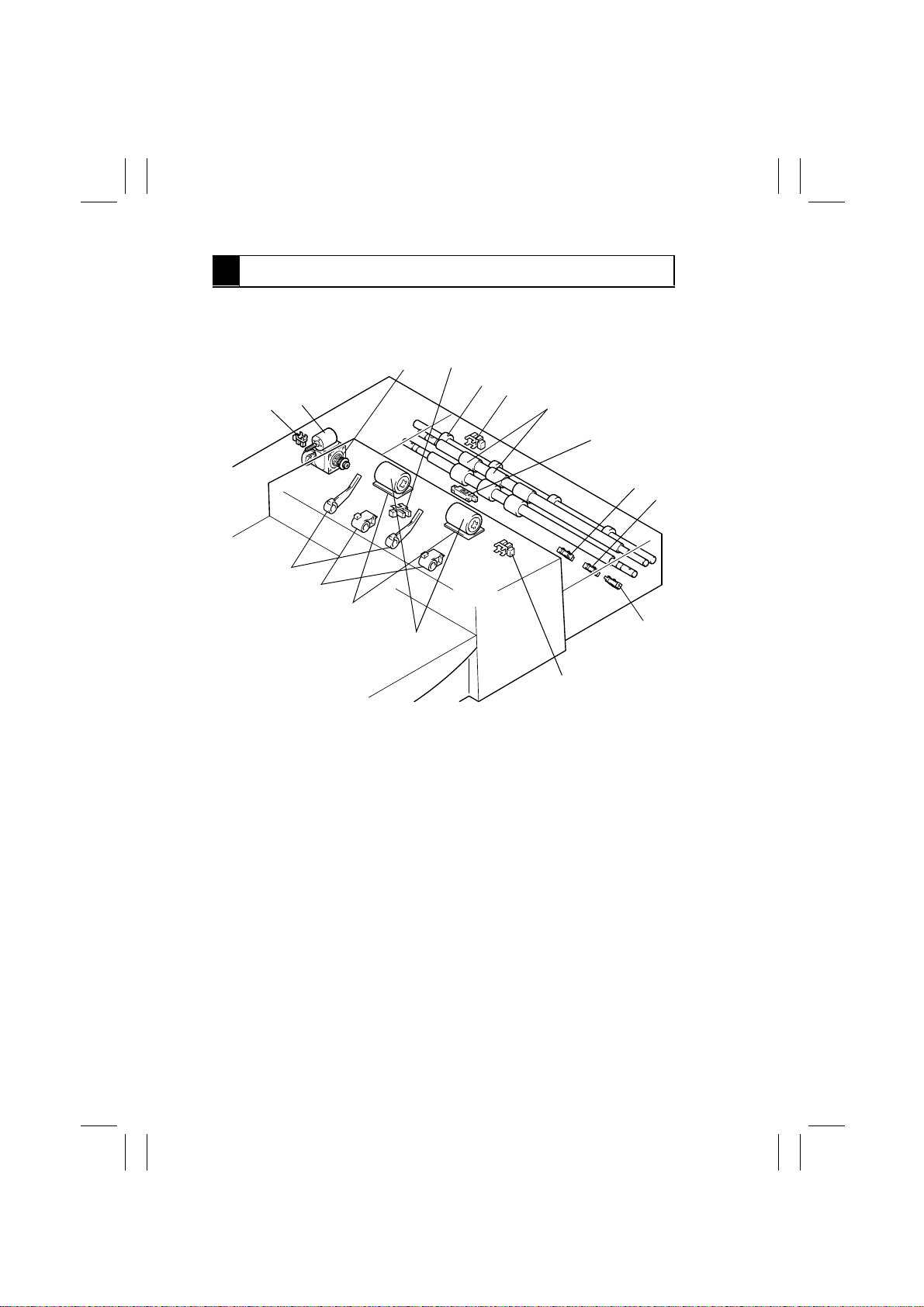
7 DOCUMENT TAKE-UP/FEEDING MECHANISM
7-1. Parts Identification
2
1
3
4
5
6
15
16
14
13
12
11
7
8
9
1. Take-Up Motor M2
2. Empty Sensor PC1
3. Single Feed Roller
4. Single Feed Empty Sensor PC9
5. Registration Roller
6. Registration Sensor PC2
7. Width Sensor 1 PC5
8. Width Sensor 2 PC6
9. Width Sensor 3 PC7
10
4490M006AB
10. Take-Up Cover Open/Close Detecting
Sensor PC10
11. Take-Up Rolls
12. Separator Pads
13. Pick-Up Rolls
14. Document Stoppers
15. Pick-Up Sensor PC8
16. Pick-Up Motor M1
M-8
Page 13
FrameMaker Ver.5.5(PC) AFR-14 OPTION FOR Di350
98.10.09
7-2. Document Pick-Up Mechanism
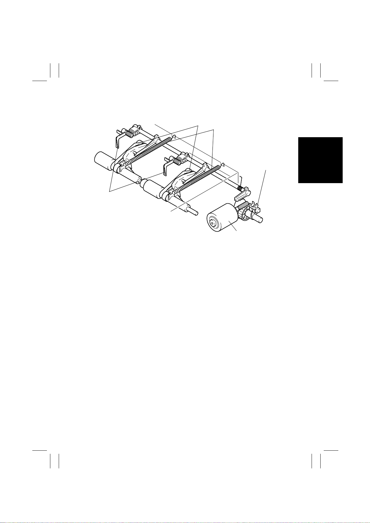
Pick-Up Rolls
Document Stoppers
Document Pressure Springs
Pick-Up Sensor PC8
Pick-Up Motor M1
4490M007AB
•
The document pick-up mechanism consists of the Document Stoppers and Pick-Up
Rolls.
•
The Document Stoppers determine the leading edge position of the document loaded in
the ADF. They are in the lowered position when in their standby position and raised when
a document take-up sequence is started.
•
The Pick-Up Rolls are in the raised position in their standby state and lowered when a
document take-up sequence is started, pressing the document set downward during the
sequence with the tension of the Document Pressure Springs.
•
The operation of the Document Stoppers and Pick-Up Rolls is controlled by Pick-Up
Motor, Pick-Up Sensor, and a cam.
M-9
Page 14
FrameMaker Ver.5.5(PC) AFR-14 OPTION FOR Di350
98.10.09
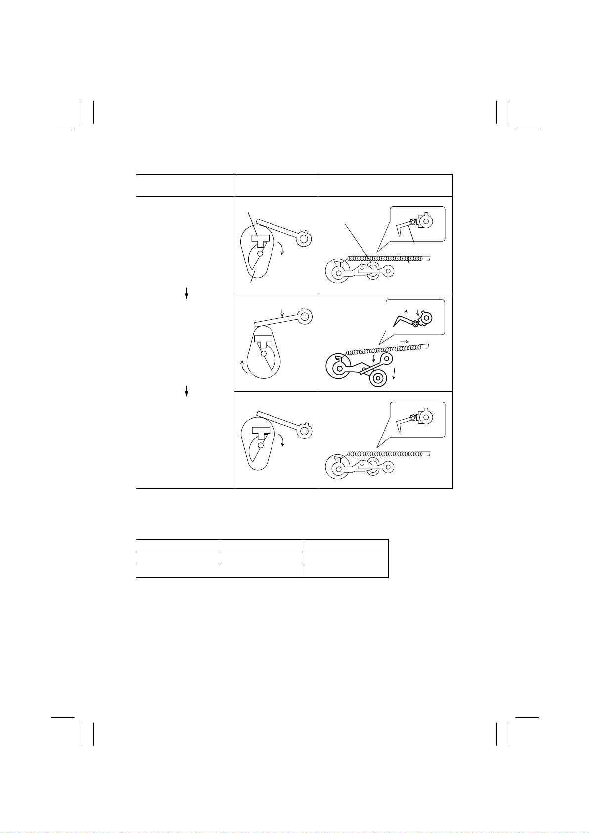
Control of Operation of the Document Stoppers and Pick-Up Rolls
Home position
Pick-Up Rolls press document; Document Stoppers
retract.
Home position
PC8 and Cam
Operation
PC8
Cam
4490M008AA
4490M010AA
Document Stoppers/Pick-Up
Rolls Operation
Pick-Up Roll
Document Stopper
Document
Pressure Spring
4490M009AA
4490M011AB
4490M008AA
4490M009AA
Pick-Up Motor Control
Pick-Up Motor is energized and deenergized by the output signals from IC1A-47 and -48 on
PWB-A as follows.
M1 IC1A-47 IC1A-48
Energized L H
Deenergized H H
M-10
Page 15
FrameMaker Ver.5.5(PC) AFR-14 OPTION FOR Di350
98.10.09
7-3. Document Take-Up Mechanism
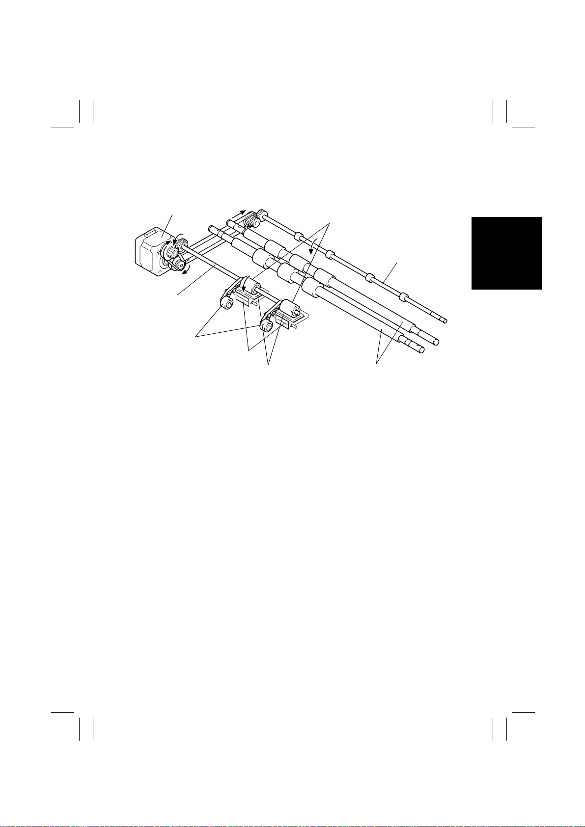
Take-Up Motor M2
Take-Up Roll Shaft
Pick-Up Rolls
Front Separator Pads
Separator Pads
•
The Pick-Up Rolls and Take-Up Rolls turn to transport the document loaded in the Document Feed Tray up to the Registration Roller.
•
The Single Feed Roller, on the other hand, turns to transport the document placed in the
Single Feed Tray.
•
The Pick-Up Rolls, Take-Up Rolls, and Single Feed Roller are driven by Take-Up Motor.
To drive the Single Feed Roller, Take-Up Motor is turned backward, at which time the
Take-Up Roll Shaft also turns backward. Because of the functioning of the one-way pulley, however, the backward rotation of the shaft is not transmitted to the Pick-Up Rolls or
Take-Up Rolls.
•
The Front Separator Pads and Separator Pads together function to prevent double feed
when two or more pages of a document set are taken up.
Take-Up Rolls
Single Feed
Roller
Registration Roller
4490M012AD
M-11
Page 16
FrameMaker Ver.5.5(PC) AFR-14 OPTION FOR Di350
98.10.09
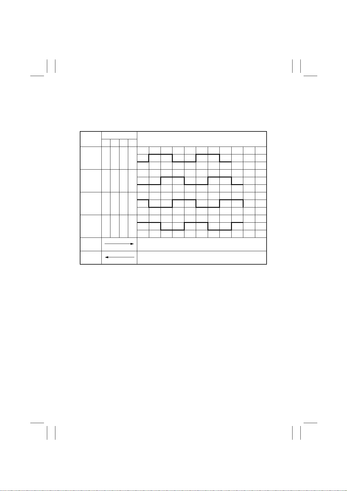
Take-Up Motor Control
•
The pulse signals output from IC12A-1, 5, 10, and 15 on PWB-A are supplied to the two
coils inside Take-Up Motor and the combination and sequence of the pulse signals energized are varied to turn Take-Up Motor forward or backw ard.
•
The distance over which an original is transported is detected by counting the number of
pulses generated.
IC12A
Pin 10 L H H L
Pin 5 L L H H
Pin 15 H L L H
Pin 1 H H L L
Forward
Rotation
Backward
Rotation
Sequence
1234
Pick-Up Rolls and Tak e-Up Rolls are turned to take up an original.
The Single Feed Roller is turned to take up an original.
M-12
Page 17
FrameMaker Ver.5.5(PC) AFR-14 OPTION FOR Di350
98.10.09
8 DOCUMENT TRANSPORT MECHANISM
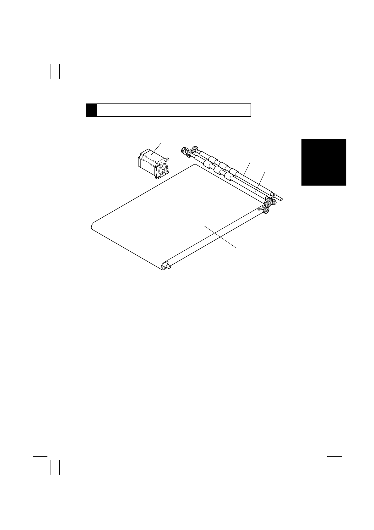
8-1. Parts Identification
1
2
3
1. Main Drive Motor M3
2. Registration Driven Roller
4
4490M013AA
3. Registration Drive Roller
4. Transport Belt
M-13
Page 18
FrameMaker Ver.5.5(PC) AFR-14 OPTION FOR Di350
98.10.09
8-2. Document Transport Mechanism
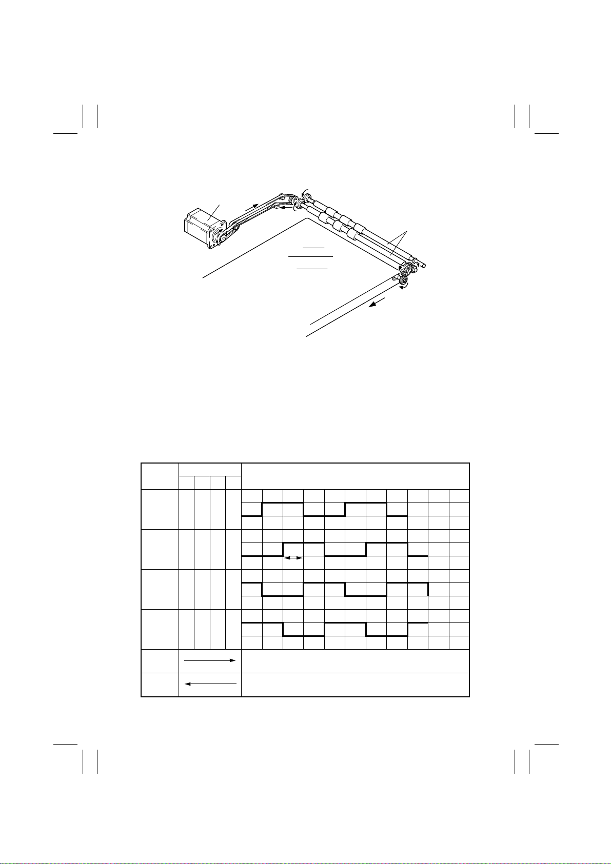
Main Drive Motor M3
Registration Rollers
Transport Belt
4490M014AA
•
Rotation of the Registration Rollers and Transport Belt results in the original fed from the
Document Feed Tray or Single Feed Tray being transported up to the Original Width
Scale.
•
The Registration Rollers and Transport Belt are driven by Main Drive Motor.
Main Drive Motor Control
•
The pulse signals output from IC10A-1, 8, 11, and 18 on PWB-A are supplied to the two
coils inside Main Drive Motor and the combination and sequence of the pulse signals
energized are varied to turn Main Drive Motor forward or backward.
•
The distance over which an original is transported is detected by counting the number of
pulses generated.
•
The motor speed is controlled by varying the cycle (A) of the pulse signal.
IC10A
Sequence
1234
Pin 8 L H H L
Pin 18 L L H H
Pin 1 H L L H
Pin 11 H H L L
Forward
Rotation
Backward
Rotation
A
Transports the original toward the Original Width Scale.
Transports the original, which has been turned over, towards
the take-up section.
M-14
Page 19
FrameMaker Ver.5.5(PC) AFR-14 OPTION FOR Di350
98.10.09
9 TURNOVER/EXIT MECHANISM
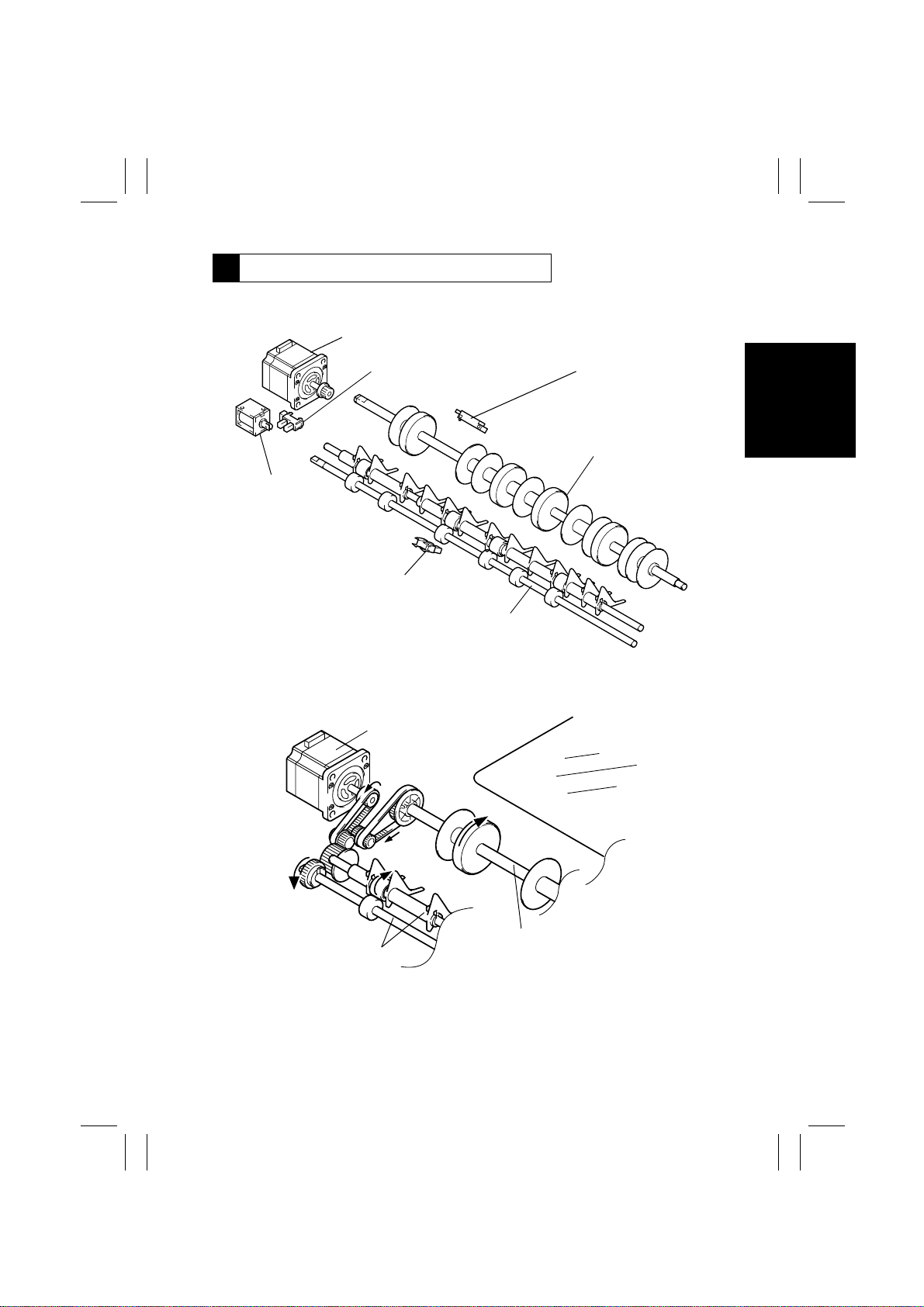
9-1. Parts Identification
Turnover/Exit Motor M4
Turnover/Exit Cover
Open/Close Detecting
Sensor PC11
Turnover/Exit
Switching
Solenoid SL1
Exit Sensor PC3
Turnover Sensor PC4
Turnover Roller
Exit Roller
4490M015AC
9-2. Document Transport Mechanism
Turnover/Exit Motor M4
Transport Belt
Turnover Roller
Exit Roller
•
The Turnover Roller and Exit Roller turn over or feed out of the ADF the original transported from the transport mechanism.
•
The Turnover Roller and Exit Roller are driven by Turnover/Exit Motor.
4490M016AC
M-15
Page 20
FrameMaker Ver.5.5(PC) AFR-14 OPTION FOR Di350
98.10.09
Turnover/Exit Motor Control
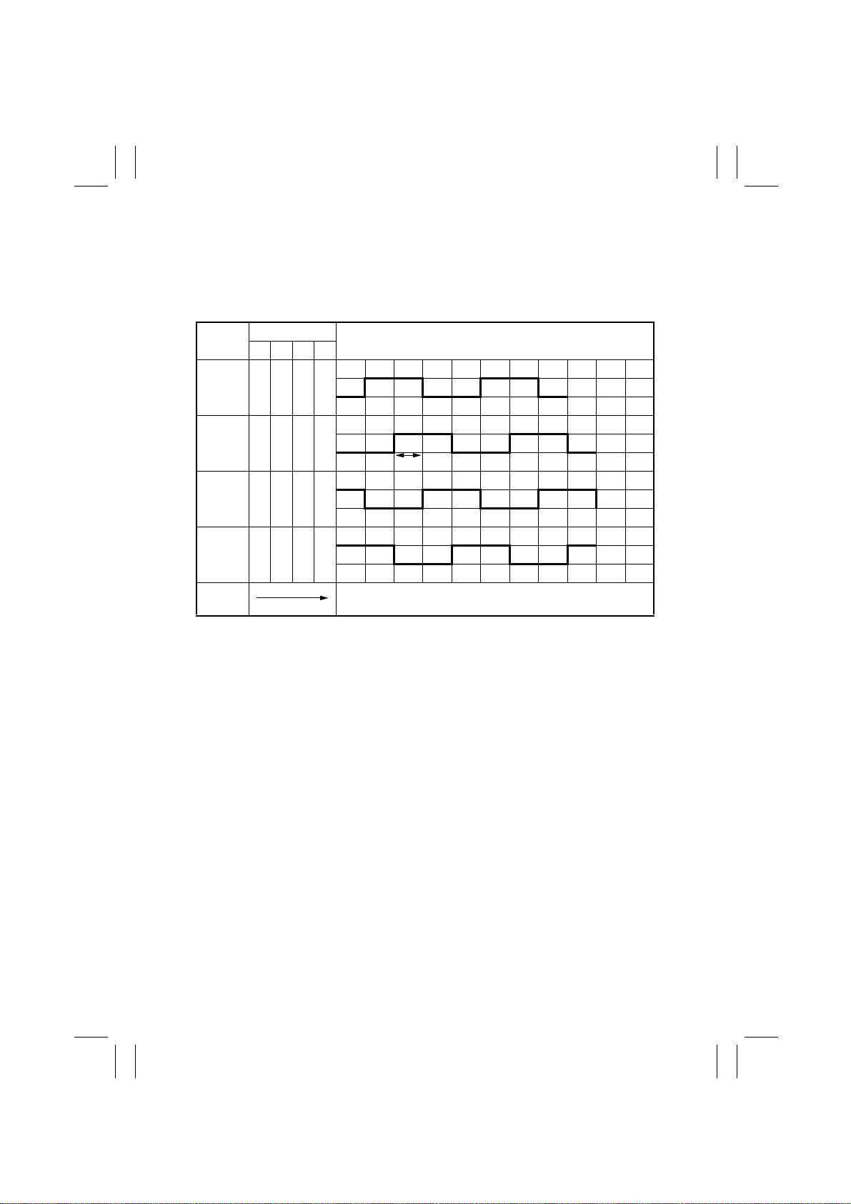
•
The pulse signals output from IC11A-1, 8, 11, and 18 on PWB-A are supplied to the two
coils inside Turnover/Exit Motor to energize Turnover/Exit Motor.
•
The distance over which an original is transported is detected by counting the number of
pulses generated.
•
The motor speed is controlled by varying the cycle (A) of the pulse signal.
IC11A
Pin 8 L H H L
Pin 18 L L H H
Pin 1 H L L H
Pin 11 H H L L
Energized
Sequence
1234
A
Transports the original towards the turnover or exit
mechanism.
M-16
Page 21
FrameMaker Ver.5.5(PC) AFR-14 OPTION FOR Di350
98.10.09
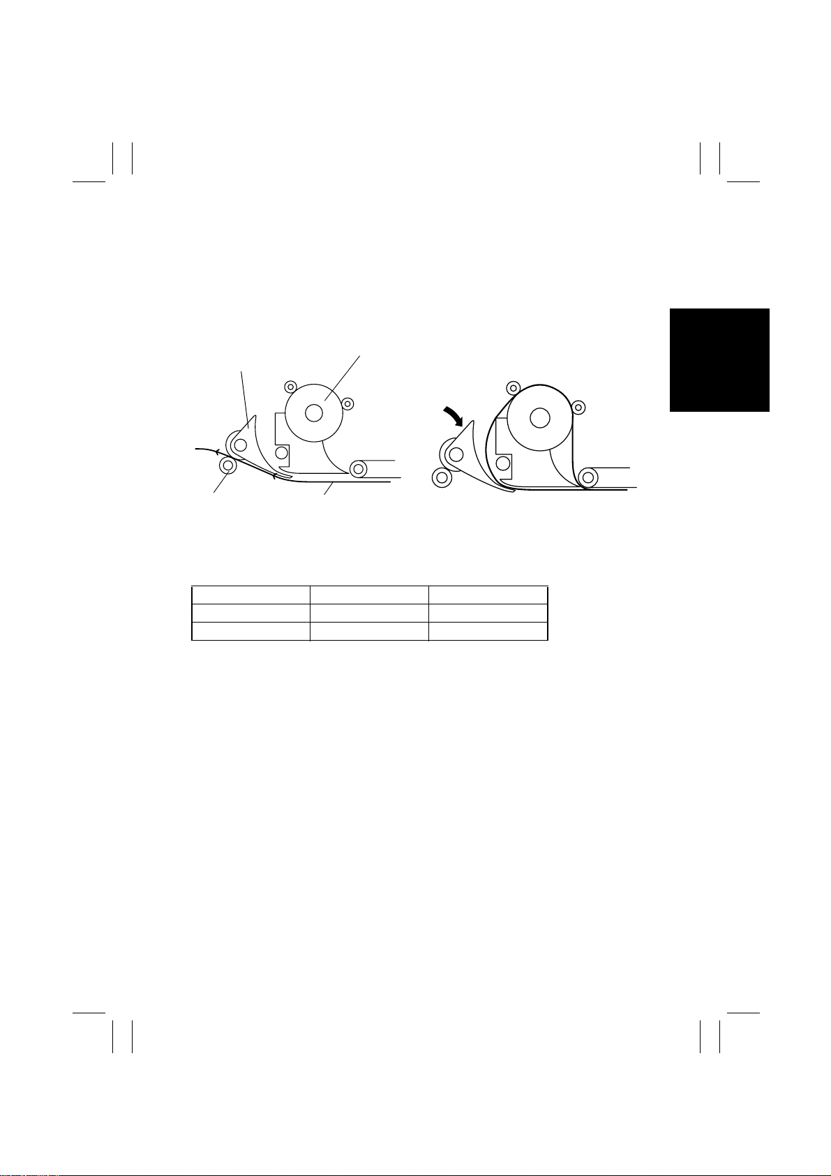
9-3. Turnover/Exit Switching Mechanism
•
The turnover/exit s witching mechanism uses the Turnover/Exit Switching Plate which is
swung downward or upward to change the document path, thereby allowing the original
to be turned over or ejected from the ADF.
•
The switching plate is actuated as Turnover/Exit Switching Solenoid is energized and
deenergized.
<For Exit>
Turnover/Exit Switching Plate
Exit Roller
Turnover/Exit Switching Solenoid Control
•
Turnover/Exit Switching Solenoid is energized and deenergized by the output from IC1A49 on PWB-A.
SL1 IC1A-49 Document Path
ON L Turnover
OFF H Exit
Original
Turnover Roller
4490M017AB
<For Turnov er>
4490M018AB
M-17
Page 22
FrameMaker Ver.5.5(PC) AFR-14 OPTION FOR Di350
98.10.09
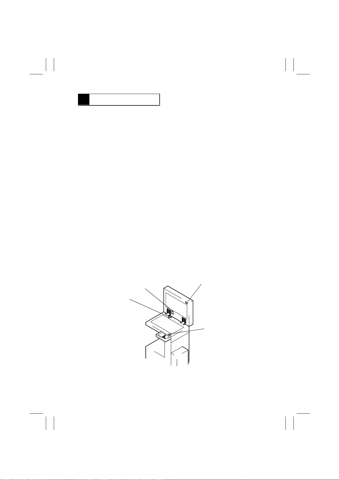
10 MISCELLANEOUS
10-1. Document Size Detection Mechanism
•
The document size is determined by means of two different systems of document width
detection and document length detection.
Document Width Detection
•
The width of an original is detected by the combination of the blocked (L) and unblocked
(H) states of Width Sensors 1 PC5, 2 PC6, and 3 PC7, as detected while the original is
being taken up.
•
Each sensor is located as follows with reference to the Document Edge Guide in the rear .
PC5: 236.5 mm; PC6: 268 mm; PC7: 288 mm
Document Length Detection
•
The length of an original is detected by counting the number of pulses generated by Main
Drive Motor for the period of time from when the Registration Roller starts turning to
when the trailing edge of the original moves past Registration Sensor.
•
In the Single Feed mode, the period of time for counting the number of pulses is up to
when the trailing edge of the original moves past Single Feed Empty Sensor.
10-2. 15° Open Detection Mechanism
•
To enable the copier to detect the document size when the ADF is used as the Original
Cover of the copier , there is the Lever Actuator provided in the ADF body.
•
The Lever Actuator mov es the Original Cover Detecting Lever mounted on the copier.
10-3. Raised/Lowered Position Detection Mechanism
•
There is a magnet installed in the ADF body to allow the copier to know that the ADF is
raised or lowered.
•
This magnet actuates the Size Reset Switch on the copier.
Lever Actuator
Original Cover Detecting Lever
Magnet
Size Reset Switch (S5)
4490M019AA
M-18
Page 23

FrameMaker Ver.5.5(PC) AFR-14 OPTION FOR Di350
98.10.09
TEST MODES
Page 24
FrameMaker Ver.5.5(PC) AFR-14 OPTION FOR Di350
98.10.09
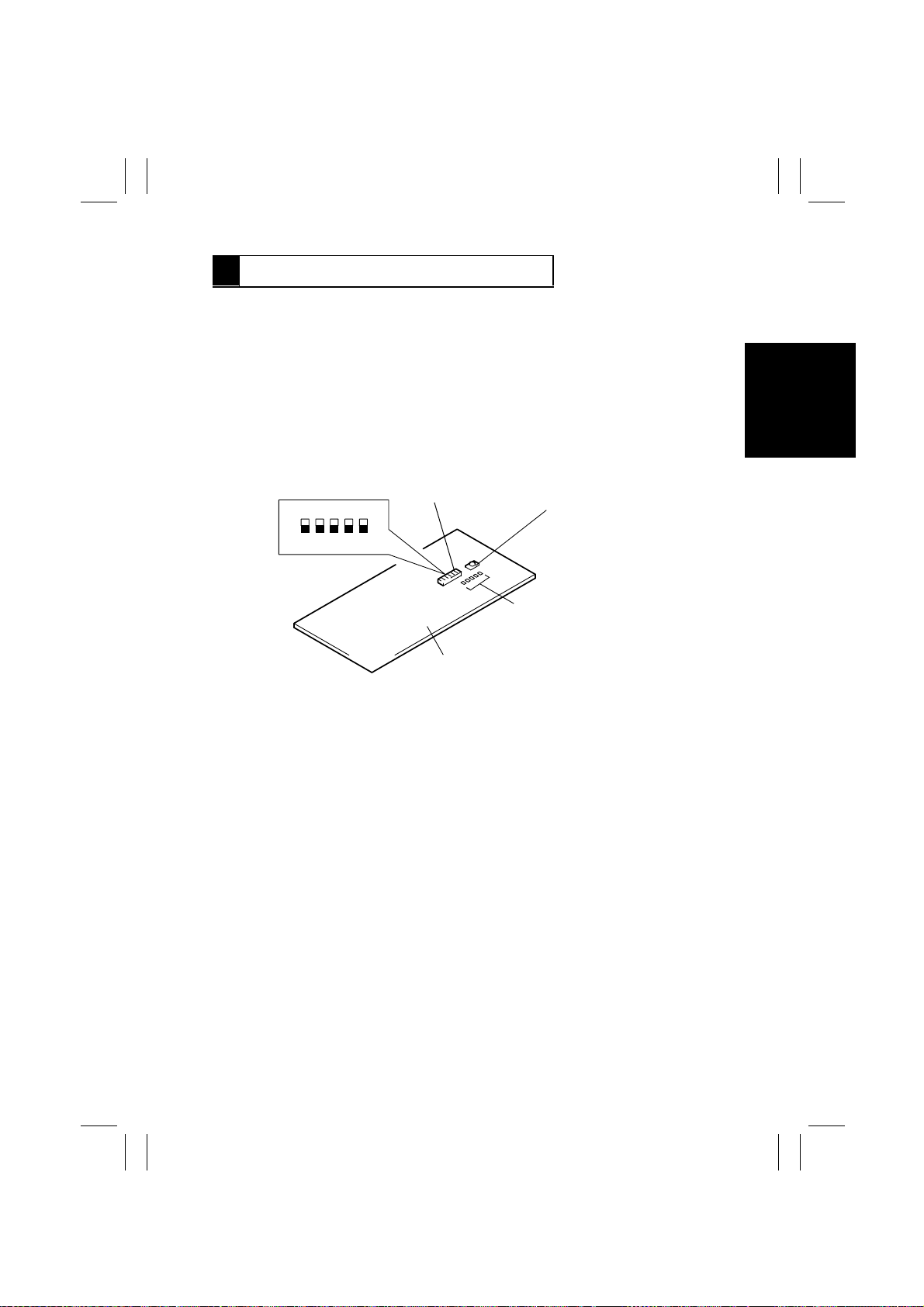
1 OUTLINE OF THE TEST MODES
•
The test modes for the ADF may be initiated from the “Tech. Rep. Mode” menu screen
provided for the copier or by changing the position of a DIP switch key on PWB-A of the
ADF.
•
For the “Tech. Rep. Mode” menu screen, see “SWITCHES ON PWBs: Tech. Rep . Mode”
of the copier’s Service Manual.
1-1. Test Mode Setting Procedure
ON
Dip Switch (S2)
1
4
2
5
3
Test Mode Switch (S1)
LED
PWB-A
•
Flip S2-5 to the ON position and turn OFF and ON the Power Switch of the copier. This
4490S001AB
sets the ADF into the Tes t mode.
•
Various types of Test Mode operations are available, each being selected with a particular combination of ON and OFF settings of S2-1 to -5. To run a particular operation, make
the correct DIP switch key settings, r aise and lower the ADF to validate the settings, and
press S1 to start the operation.
1-2. Types of Test Modes
•
The following four types of Test Modes are available:
Paper Passage Check
Unit Check
Sensor Check
Board Check
S-1
Page 25
FrameMaker Ver.5.5(PC) AFR-14 OPTION FOR Di350
98.10.09
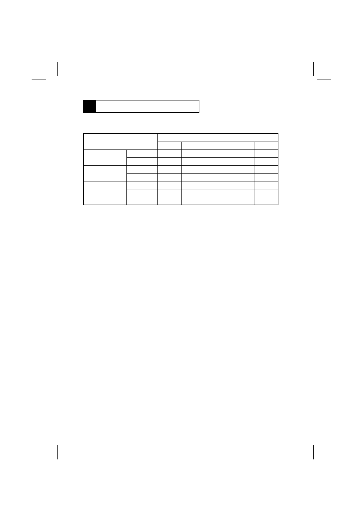
2 PAPER PASSAGE CHECK
2-1. Paper Passage Modes
Paper Passage Mode
1-Sided Continuous ON
Intermittent ON ON
Mixed Original Continuous ON ON
Intermittent ON ON ON
2-Sided Continuous ON ON
Intermittent ON ON ON
Single Feed Intermittent ON ON ON
(Blank means OFF.)
✽
To adjust the stop position, flip S2-3 to ON. The adjustment procedure will be found in
DIS/REASSEMBLY, ADJUSTMENT to follow.
12345
S2
2-2. Paper Passage Check Procedure
1. Turn OFF the Power Switch of the copier and flip S2-5 to ON.
2. Turn ON the Power Switch of the copier. (This sets the ADF into the Test Mode.)
3. Make the necessary settings of S2-1 to -4 for the desired paper passage mode.
4. Raise and lower the ADF.
5. Load a document set in the Document Feed T ray.
6. Press S1 once.
7. This starts the paper passage check.
✽
To interrupt a continuous paper passage mode (S2-4: OFF), press S1 once . I f S1 is then
pressed a second time, the ADF feeds all originals out of itself to terminate the paper
passage mode.
✽
In an intermittent paper passage mode (S2-4: ON), each press of S1 lets the ADF feed
an original through itself.
✽
To select either the continuous or intermittent mode, turn OFF the Power Switch of the
copier, flip S2-4 to OFF and then ON, and turn ON the Power Switch.
S-2
Page 26
FrameMaker Ver.5.5(PC) AFR-14 OPTION FOR Di350
98.10.09
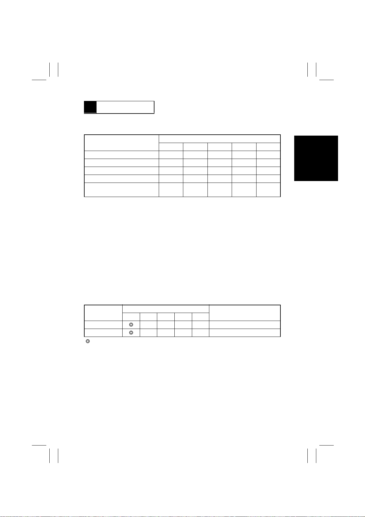
3 UNIT CHECK
3-1. Unit Check Modes
Unit Check Mode
Pick-Up Mo tor M1 ON ON
Take-Up Motor M2 ON
Main Drive Motor M3 ON ON
Turnover/Exit Motor M4 ON ON
Turnover/Exit Switching
Solen o id SL1
(Blank means OFF.)
✽
Flipping S2-4 to ON before the Power Switch is turned ON allows for setting t he ADF into
the Durability mode which, once started, continues running until stopped.
12345
ON ON ON
S2
3-2. Unit Check Procedure
1. Turn OFF the Power Switch of the copier and flip S2-5 to ON. (Flip S2-4 to ON for the
Durability mode.)
2. Turn ON the Power Switch of the copier. (This sets the ADF into the Test Mode.)
3. Make the necessary settings of S2-1 to -5 for the desired unit check mode.
4. Raise and lower the ADF.
5. This completes the setting of the unit check mode.
Pick-Up Motor check:
•
Each press of S1 repeats the operation shown below.
No. of Times S1
is Pressed
0
1
( : Blinking, ❍: OFF, ●: ON)
12345
LED
❍❍❍❍
❍❍❍●
Standby
Rotation (Take-Up Rolls down)
Operation
S-3
Page 27
FrameMaker Ver.5.5(PC) AFR-14 OPTION FOR Di350
98.10.09
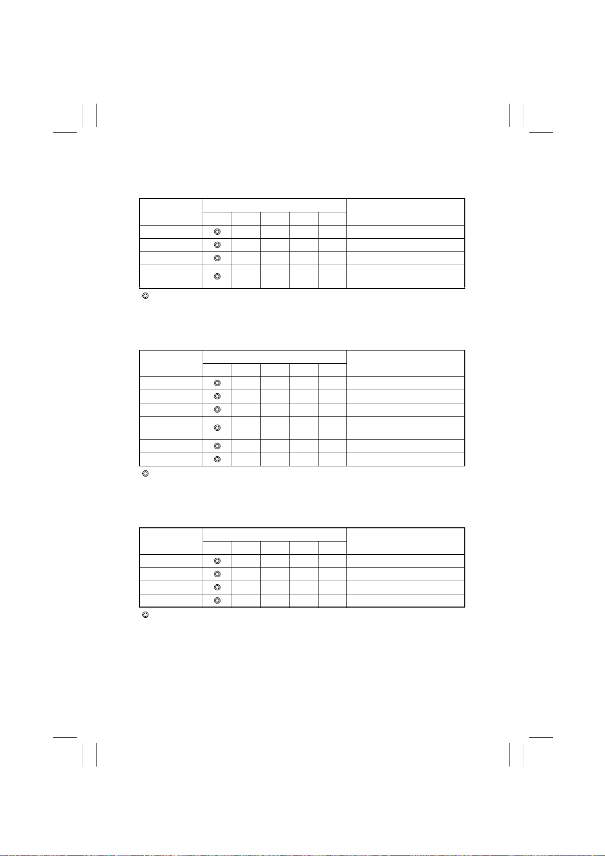
Take-Up Motor check:
•
Each press of S1 repeats the operation shown below.
•
The motor automatically stops turning in about 60 sec.
No. of Times S1
is Pressed
0
1
2
3
( : Blinking, ❍: OFF, ●: ON)
Main Drive Motor check:
•
Each press of S1 repeats the operation shown below.
•
The motor automatically stops turning in about 60 sec.
No. of Times S1
is Pressed
0
1
2
3
4
5
( : Blinking, ❍: OFF, ●: ON)
Turnover/Exit Motor check:
•
Each press of S1 repeats the operation shown below.
•
The motor automatically stops turning in about 60 sec.
12345
12345
LED
❍❍❍❍
❍❍❍●
❍❍●❍
❍❍●●
LED
❍❍❍❍
❍❍❍●
❍❍●❍
❍❍●●
❍●❍❍
❍●❍●
Operation
Standby
Forward rotation (150 mm/sec.)
Stop
Backward rotation (300 mm/
sec.)
Operation
Standby
Forward rotation (650 mm/sec.)
Stop
Backward rotation (650 mm/
sec.)
Stop
Forward rotation (300 mm/sec.)
No. of Times S1
is Pressed
0
1
2
3
( : Blinking, ❍: OFF, ●: ON)
12345
LED
❍❍❍❍
❍❍❍●
❍❍●❍
❍❍●●
Standby
Rotation (650 mm/sec.)
Stop
Rotation (300 mm/sec.)
S-4
Operation
Page 28
FrameMaker Ver.5.5(PC) AFR-14 OPTION FOR Di350
98.10.09
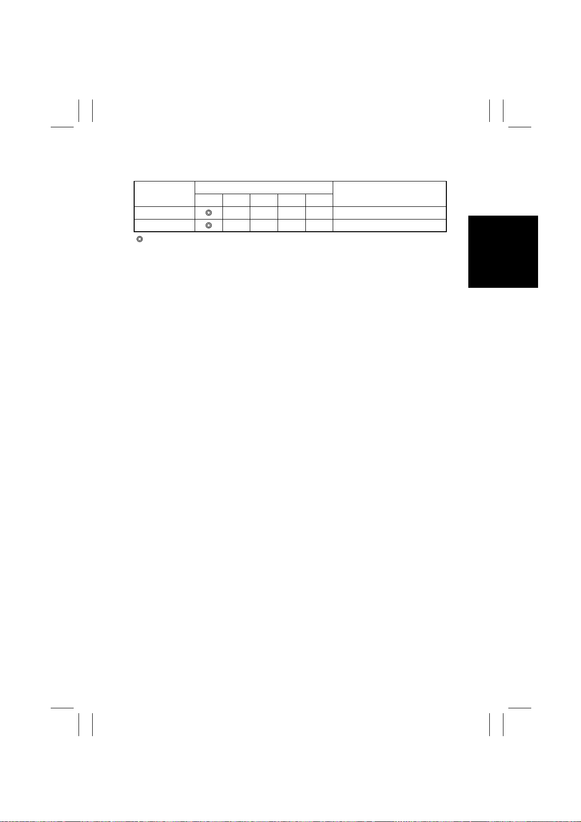
Turnover/Exit Switching Solenoid SL1 check:
•
Each press of S1 repeats the operation shown below.
No. of Times S1
is Pressed
0
1
( : Blinking, ❍: OFF, ●: ON)
12345
LED
❍❍❍❍
❍❍❍●
Standby
Energized
Operation
S-5
Page 29
FrameMaker Ver.5.5(PC) AFR-14 OPTION FOR Di350
98.10.09
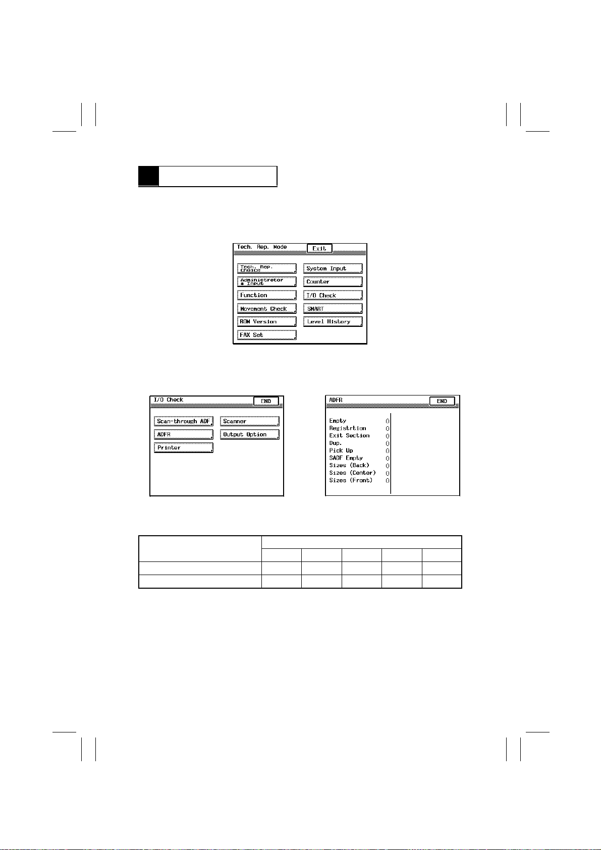
4 SENSOR CHECK
4-1. Sensor Check Mode
•
“Tech. Rep. Mode” menu screen on the copier Touch Panel:
1. Select “I/O Check” on the “Tech. Rep. Mode” menu screen.
4490S007CA
2. Select “ADFR.”
3. Using a sheet of paper or other device, activate the sensor to be checked and check the
data shown on the screen (paper present: 1; paper not present: 0).
4490S008CA
•
DIP Switch S2 on PWB-A of this ADF:
Mode
Sensor Check 1
Sensor Check 2 ON
(Blank means OFF.)
Sensor Check 1:
•
Empty Sensor PC1
•
Registration Sensor PC2
•
Exit Sensor PC3
•
Turnover Sensor PC4
4490S009CA
S2
12345
Sensor Check 2
•
Single Feed Empty Sensor PC9
•
Width Sensor 1 PC5
•
Width Sensor 2 PC6
•
Width Sensor 3 PC7
S-6
Page 30
FrameMaker Ver.5.5(PC) AFR-14 OPTION FOR Di350
98.10.09
4-2. Sensor Check Procedure
1. Turn OFF the Power Switch of the copier and flip S2-5 to ON.
2. Turn ON the Power Switch of the copier. (This sets the ADF into the Test Mode.)
3. Make the necessary settings of S2-1 to -5 for the desired sensor check mode.
4. Raise and lower the ADF.
5. This completes the setting of the sensor check mode.
Sensor Check 1 check:
•
Using a sheet of paper or other device, activate the sensor to be checked and check for
the LED condition.
Sensor
Empty Sensor PC1
Registration Sensor PC2
Exit Sensor PC3
Turnover Sensor PC4
( : Blinking, ❍: OFF, ●: ON)
Sensor Check 2 check:
•
Using a sheet of paper or other device, activate the sensor to be checked and check for
the LED condition.
Sensor
Single Feed Empty Sensor PC9
Width Sensor 1 PC5
Width Sensor 2 PC6
Width Sensor 3 PC7
( : Blinking, ❍: OFF, ●: ON)
12345
12345
LED
❍❍❍●
❍❍●❍
❍●❍❍
●❍❍❍
LED
❍❍❍●
❍❍●❍
❍●❍❍
●❍❍❍
Operation
Blocked
Blocked
Unblocked
Blocked
Operation
Blocked
Unblocked
Unblocked
Unblocked
S-7
Page 31

FrameMaker Ver.5.5(PC) AFR-14 OPTION FOR Di350
98.10.09
5 BOARD CHECK
5-1. Board Check Mode
•
Each electrical component is energized sequentially to determine if the drive circuit of
PWB-A is fully operational.
1. Turn OFF the Power Switch of the copier and flip S2-4 to ON.
2. Turn ON the Power Switch of the copier.
3. This completes the setting of the board check mode.
5-2. Board Check Procedure
•
Each press of S1 energizes the following electrical components in that order, one at a
time.
1. Turnover/Exit Switching Solenoid is energized and, in one sec., deenergized.
2. Pick-Up Motor turns.
3. Take-Up Motor turns. (150 mm/sec.)
4. Main Drive Motor turns. (650 mm/sec.)
5. Turnover/Exit Motor turns. (650 mm/sec.)
6. All energized components are deenergized.
S-8
Page 32

FrameMaker Ver.5.5(PC) AFR-14 OPTION FOR Di350
98.10.09
DIS/REASSEMBLY,
ADJUSTMENT
Precautions for Disassembly, Reassembly, and Adjustment
1. Before attempting to disassemble the ADF, always make sure that no power is being
supplied from the copier.
2. While power is being supplied to the ADF, do not attempt to remove/install the print
jacks from/to the PWBs or unplug/plug in the connectors.
3. If the ADF is run with its covers removed, use care not to allow your clothing to be
caught in the belt or other moving parts.
4. The basic rule is do not run the ADF with any of its parts removed.
5. A toothed washer is used with the screw that secures the ground wire to ensure positive
conduction. Do not forget to use this washer at reassembly.
6. To reassemble the ADF, reverse the order of disassembly unless otherwise specified.
7. Do not attempt to remove or loosen the screws to which red paint has been applied.
Purpose of Application of Red Paint
Red paint is applied to the screws of parts that cannot be readjusted, set, or reinstalled in
the field.
Page 33
FrameMaker Ver.5.5(PC) AFR-14 OPTION FOR Di350
98.10.09
1 DISASSEMBLY
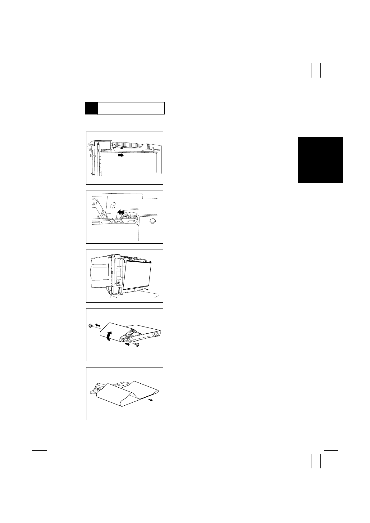
1-1. Removal of the Transport Belt
1. Snap off the C-clip.
4490D001AB
2. Unlock the holder that holds the Transpor t Belt
Drive Roller.
4490D002AB
4490D003AA
4490D004AB
4490D005AA
3. Pull the Transport Belt Roller Assy toward you
and remove it from the ADF.
4. Remove two screws and bend the roller unit
inward.
5. Remove the Transport Belt.
D-1
Page 34
FrameMaker Ver.5.5(PC) AFR-14 OPTION FOR Di350
98.10.09
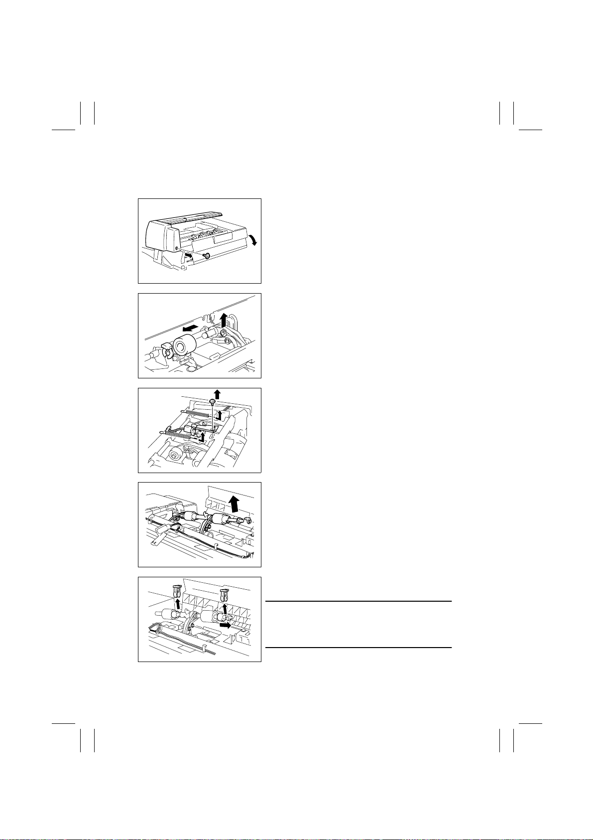
1-2. Removal of the Pick-Up Rolls, Take-Up Rolls, and Separator
Pads
1. Open the Take-Up Cover and remove one screw
and the Upper Cover.
4490D006AB
2. Lift the Pick-Up Roll Arm.
3. Snap off the C-clip from the Pick-Up Roll Shaft
and remove the Pick-Up Roll.
4490D007AB
4490D008AB
4490D009AB
4490D010AB
4. Unhook the two springs from the Pick-Up Roll
Arm.
5. Remove one screw and the Paper Empty Sensor.
6. Snap off the C-clip.
7. Slide off the bushing and raise the shaft.
8. Snap off the C-clips and remove the Take-Up
Rolls from their shaft.
Note
When reinstalling the Take-Up Rolls, make sure that
the blue end of the one-way bearing is on the side
opposite the Take-Up Roll.
D-2
Page 35
FrameMaker Ver.5.5(PC) AFR-14 OPTION FOR Di350
98.10.09
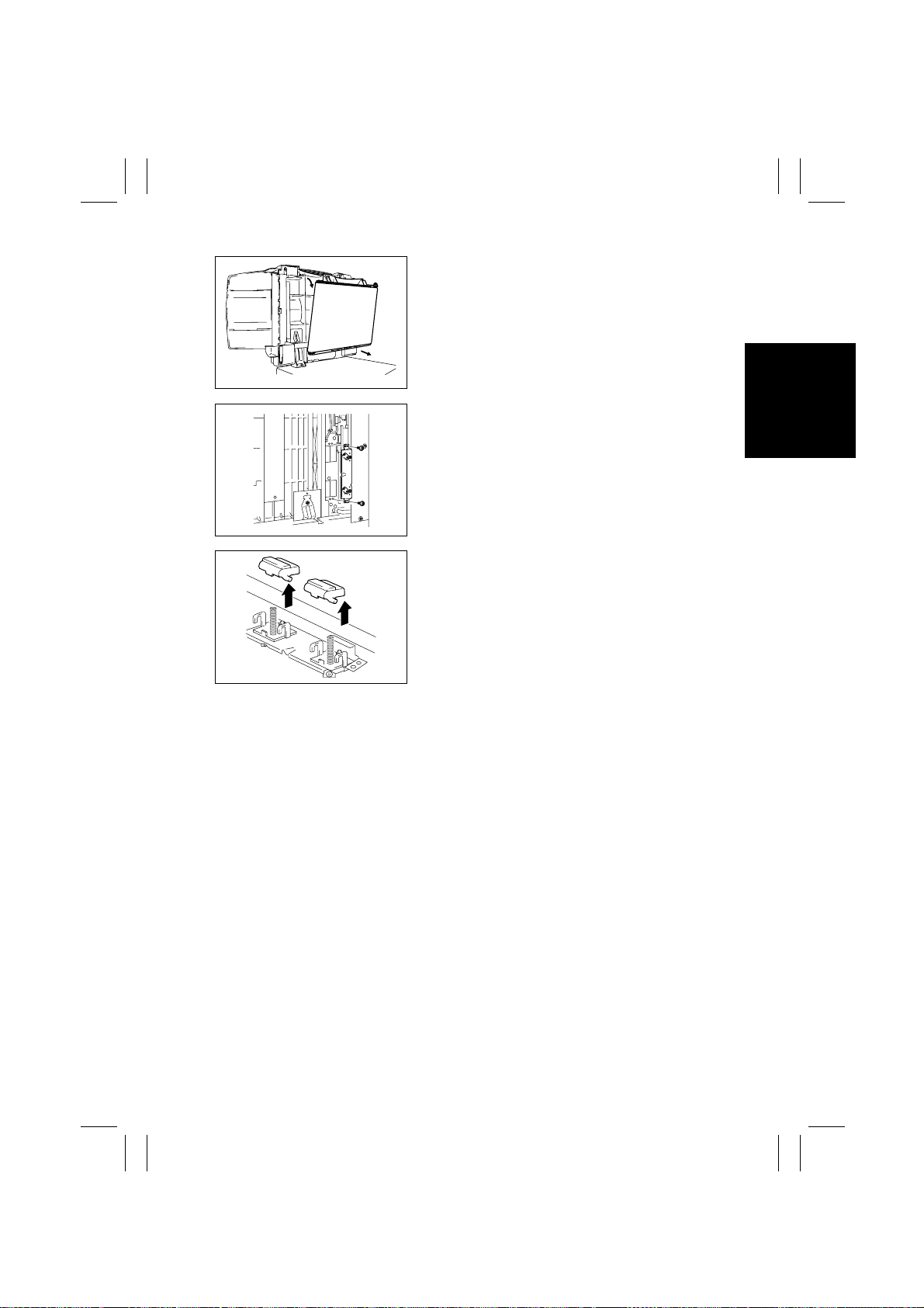
9. Remove the Transport Belt Roller Assy.
4490D003AA
10. Remove two screws and the Separator Pad
Assy .
4490D012AA
11. Remove the Separator Pads.
4490D013AB
D-3
Page 36
FrameMaker Ver.5.5(PC) AFR-14 OPTION FOR Di350
98.10.09
2 ADJUSTMENTS
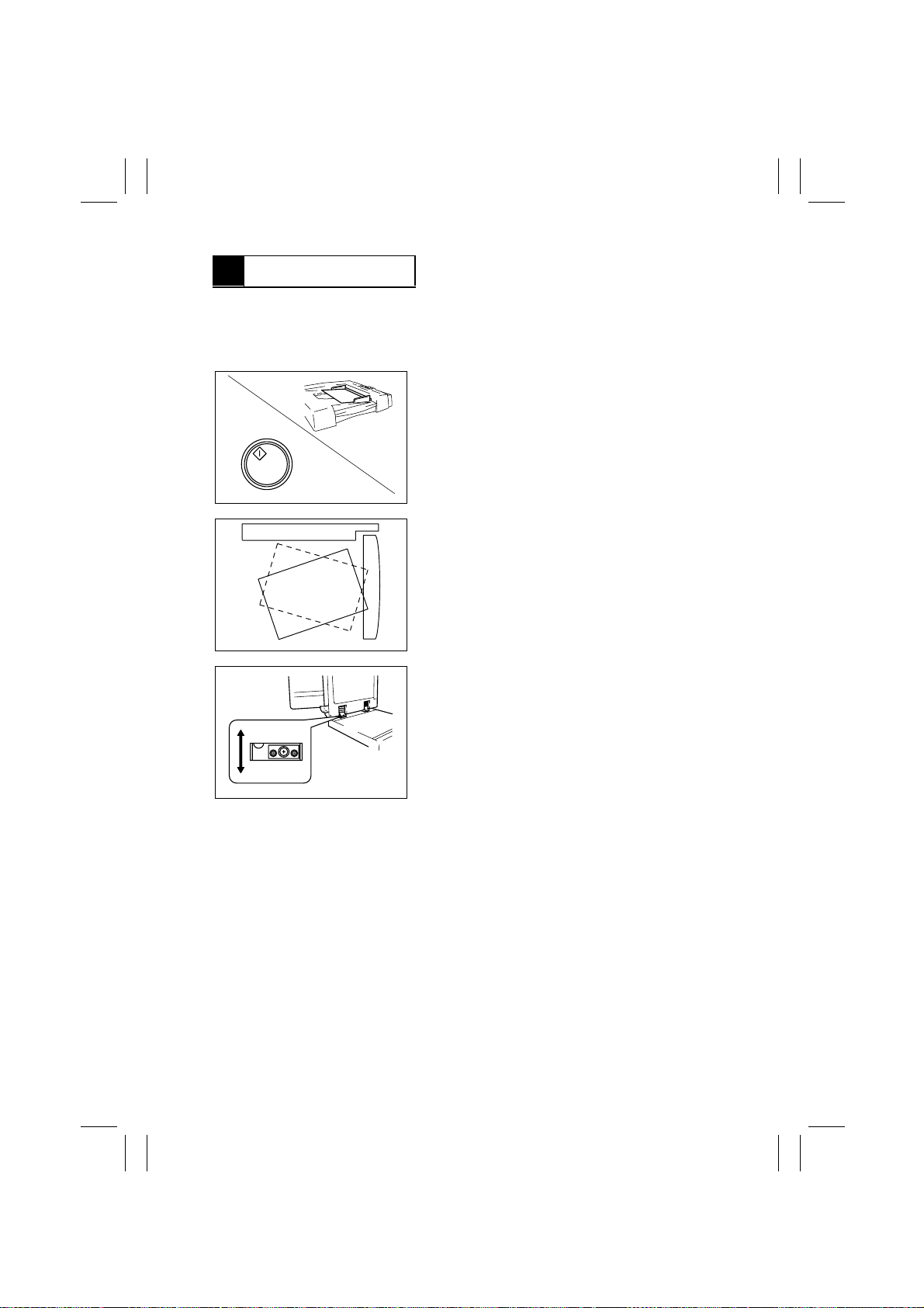
2-1. Adjustment of Skew in the ADF
Requirement: Skew should be 0.35% or less with respect to the document length. For A4
crosswise: 1.0 mm
1. Slide out all drawers from the copier.
2. Load an original in the Document Feed Tray and
select 1-Sided mode.
3. Press the Start key.
4. Gently raise the ADF.
4490D011AA
5. Check in which direction, a or b, the original positioned on the Original Glass tilts.
a
b
4490D014AB
4490D015AA
6. Loosen the three screws of the left hinge.
7. If the original tilts in the direction of a, move the
ADF to the front.
If the original tilts in the direction of b, move the
ADF to the rear.
8. Tighten the three screws.
✽
After this adjustment has been made, perform the
following steps: Adjustment of the Document Feed
Tray Reference Position and Adjustment of the
Document Stop Position in each mode.
D-4
Page 37
FrameMaker Ver.5.5(PC) AFR-14 OPTION FOR Di350
98.10.09
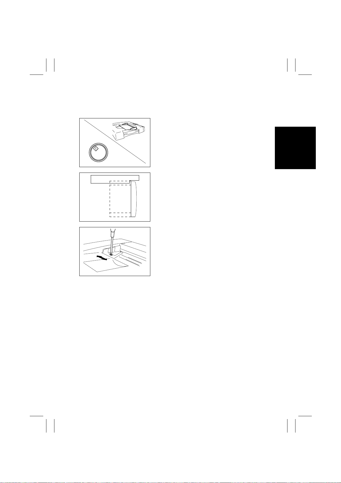
2-2. Adjustment of the Document Feed Tray Reference Position
Requirement: The deviation of the edge of the original with respect to the Original Length
Scale should be 4 ± 1 mm.
1. Slide out all drawers from the copier.
2. Load an original in the Document Feed Tray and
select 1-Sided mode.
3. Press the Start key.
4. Gently raise the ADF.
4490D011AA
a
b
4490D016AB
4490D017AB
5. Check in which direction, a or b, the original positioned on the Original Glass deviates with respect
to the Original Length Scale.
6. Loosen the screw shown.
7. If the original deviates in the direction of a, move
the Document Feed Guide to the front.
If the original deviates in the direction of b, move
the Document Feed Guide to the rear.
8. Tighten the screw.
D-5
Page 38
FrameMaker Ver.5.5(PC) AFR-14 OPTION FOR Di350
98.10.09
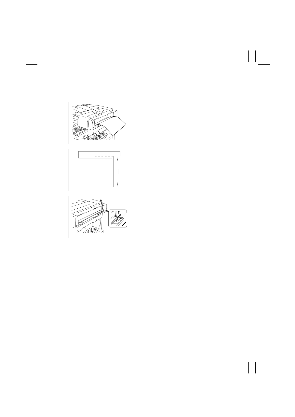
2-3. Adjustment of the Single Feed Tray Reference Position
Requirement: The deviation of the edge of the original with respect to the Original Length
Scale should be 4 ± 1 mm.
1. Slide out all drawers from the copier.
2. Insert an original into the Single Feed Tray.
3. Gently raise the ADF.
4490D018AA
a
b
4490D016AB
4490D019AA
4. Check in which direction, a or b, the original positioned on the Original Glass deviates with respect
to the Original Length Scale.
5. Loosen the screw shown.
6. If the original deviates in the direction of a, move
the Single Feed Guide to the front.
If the original deviates in the direction of b, move
the Single Feed Guide to the rear.
7. Tighten the screw.
D-6
Page 39
FrameMaker Ver.5.5(PC) AFR-14 OPTION FOR Di350
98.10.09
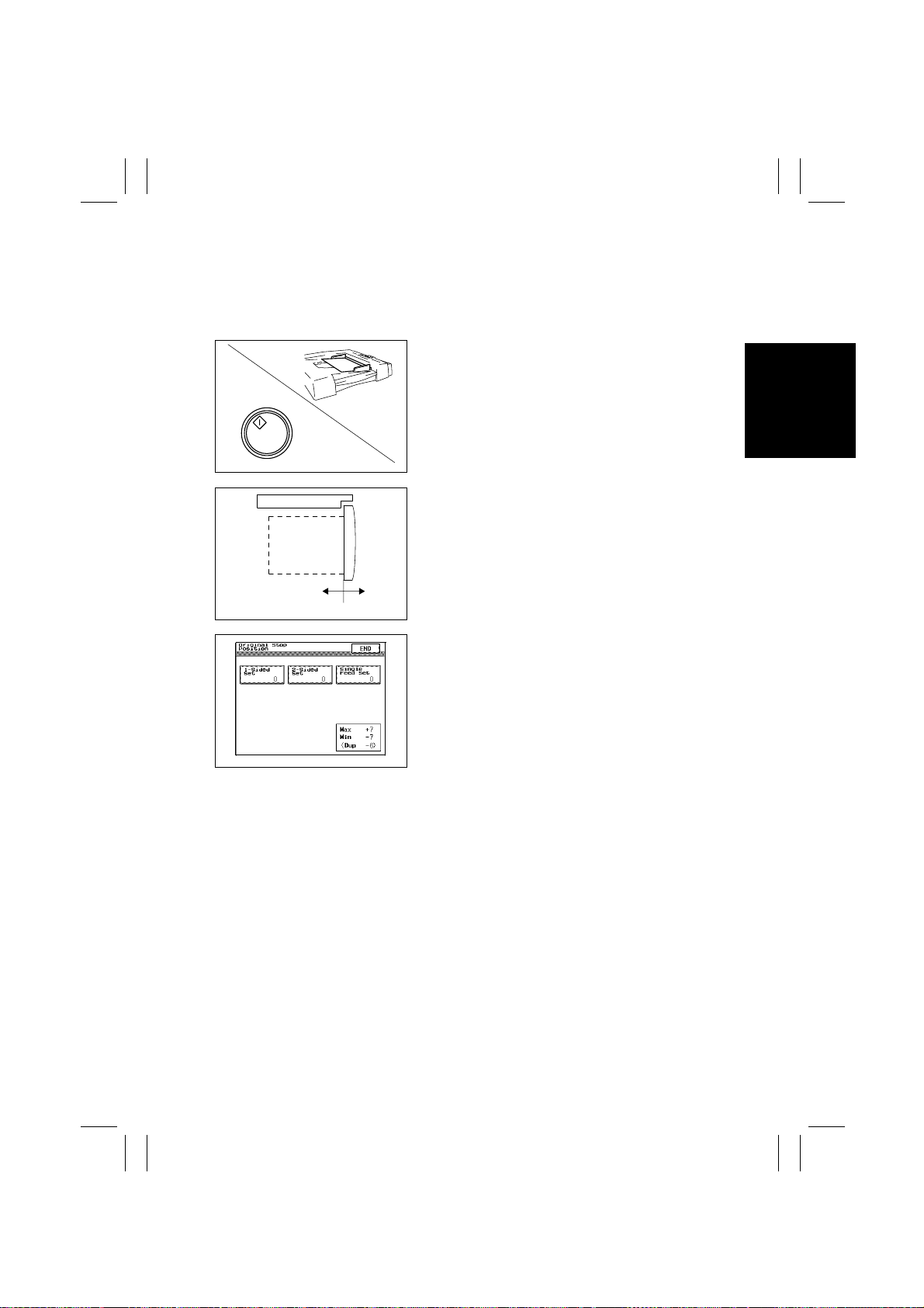
2-4. Adjustment of the Document Stop Position in the 1-Sided
and 1-Sided Mixed Original Mode
Requirement: The deviation of the edge of the original with respect to the Original Width
Scale should be 0 ± 1 mm.
1. Slide out all drawers from the copier.
2. Load an original in the Document Feed Tray and
➝
1 mode.
C
4490D011AA
D
4490D020AB
select the 1
3. Press the Start key.
4. Gently raise the ADF.
5. Determine how much (in mm) the original positioned on the Original Glass is off in the direction
of C or D with respect to the Original Width Scale.
4490S010CA
6. Select the functions in the following order: Tech.
Rep. Mode
Original Stop Position ➝ 1-Sided Set.
➝
Tech. Rep. Choice ➝ ADFR
➝
7. Referring to “Document Stop Position Setting
Procedure” on p. D-9, adjust the document stop
position.
D-7
Page 40
FrameMaker Ver.5.5(PC) AFR-14 OPTION FOR Di350
98.10.09
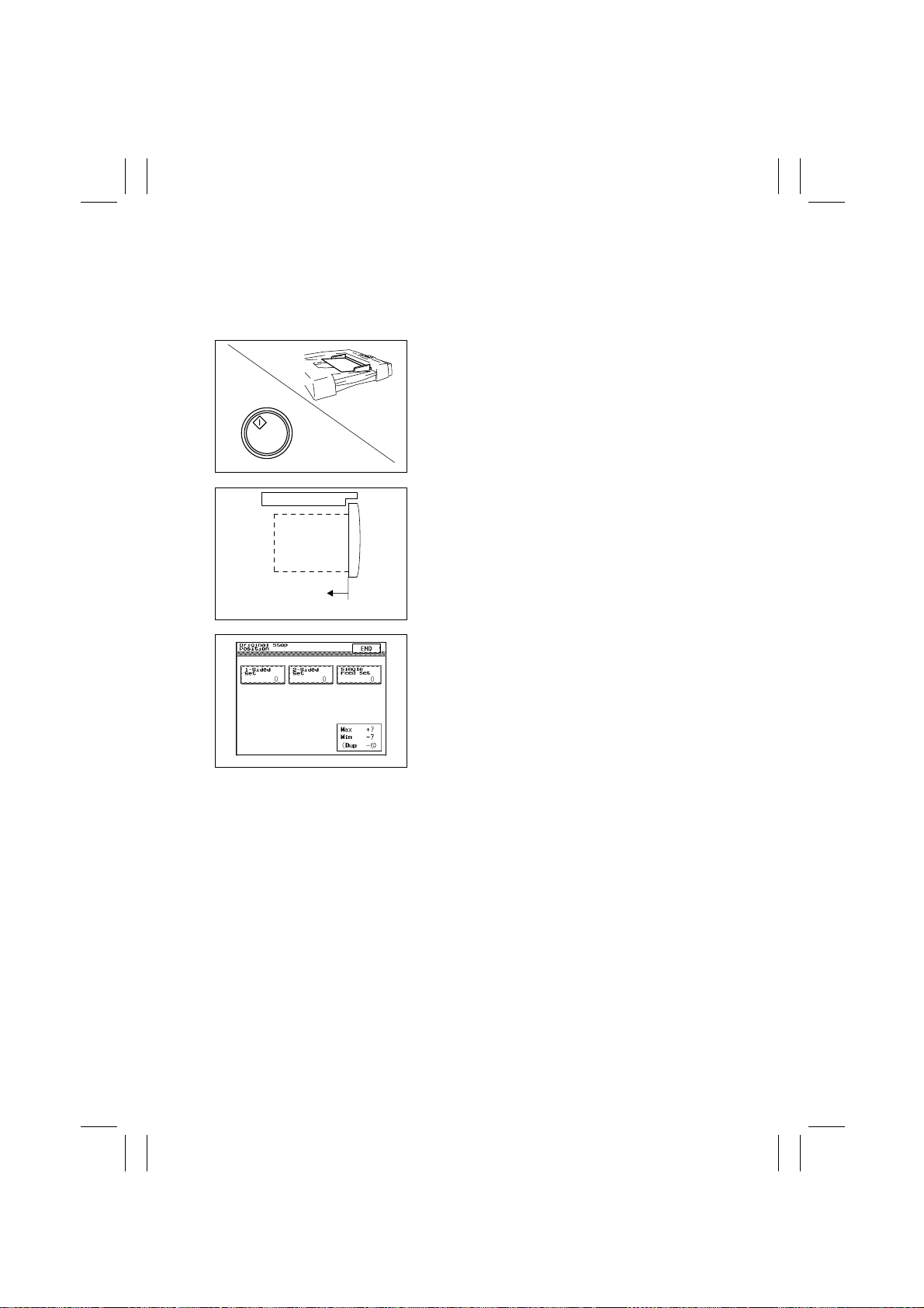
2-5. Adjustment of the Document Stop Position in the 2-Sided
Mode
Requirement: The deviation of the edge of the original with respect to the Original Width
Scale should be 0 ± 1 mm.
1. Load an original in the Document Feed Tray and
select the 2
2. Press the Start key.
3. When the second face of the original is positioned on the Original Glass, open the Take-Up
Cover.
4490D011AA
4. Gently raise the ADF.
5. Determine how much (in mm) the original positioned on the Original Glass is off in the direction
of C with respect to the Original Width Scale.
2 mode.
➝
C
4490D021AB
4490S010CA
6. Select the functions in the following order: Tech.
Rep. Mode
Original Stop Position
7. Referring to “Document Stop Position Setting
Procedure” on p. D-9, adjust the document stop
position.
Tech. Rep. Choice ➝ ADFR ➝
➝
2-Sided Set.
➝
D-8
Page 41
FrameMaker Ver.5.5(PC) AFR-14 OPTION FOR Di350
98.10.09
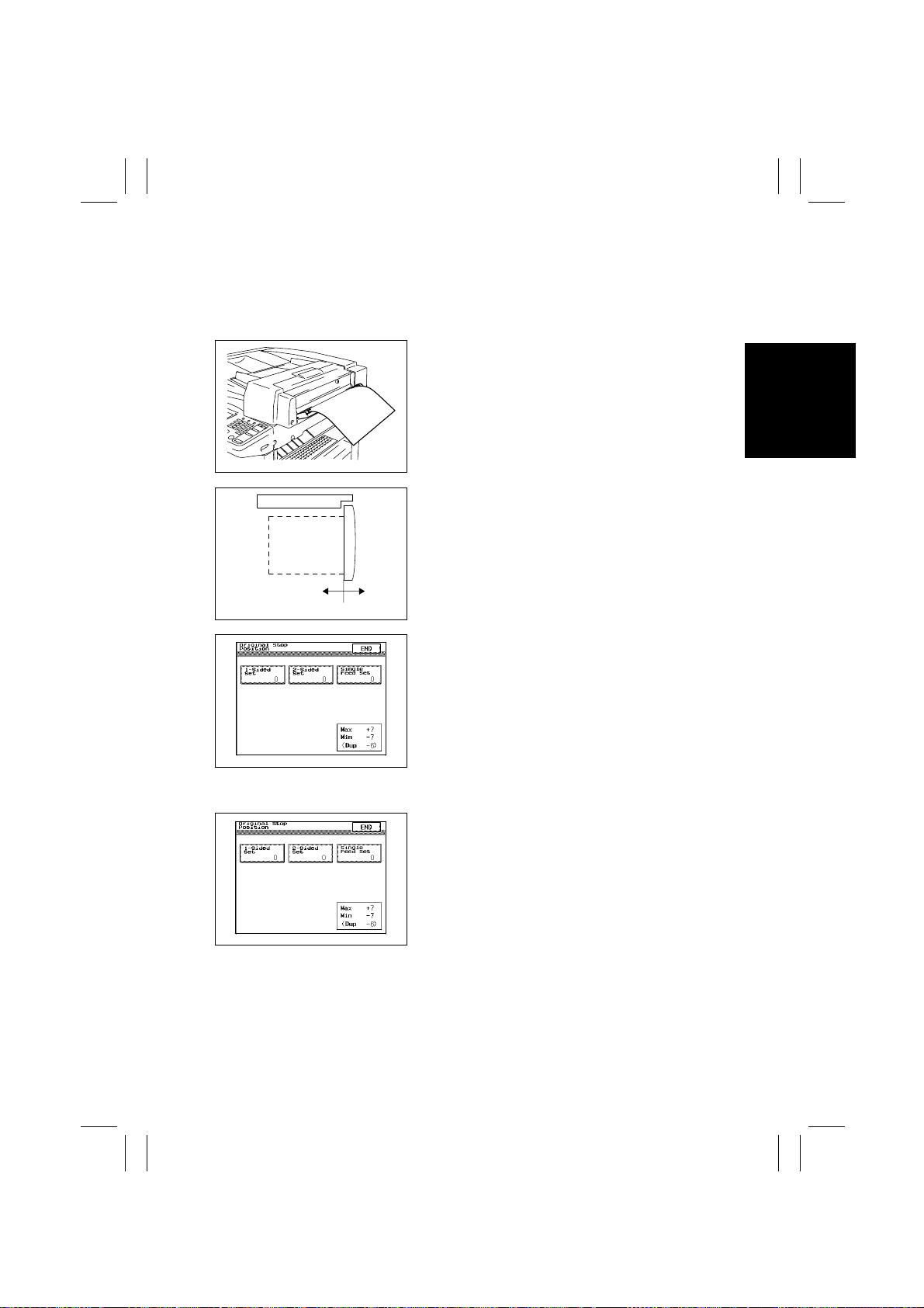
2-6. Adjustment of the Document Stop Position in the Single
Feed Mode
Requirement: The deviation of the edge of the original with respect to the Original Width
Scale should be 0 ± 1 mm.
1. Slide out all drawers from the copier.
1 mode and insert an original into
➝
C
4490D018AA
D
4490D020AB
2. Select the 1
the Single Feed Tray.
3. Gently raise the ADF.
4. Determine how much (in mm) the original positioned on the Original Glass is off in the direction
of C or D with respect to the Original Width Scale.
5. Select the functions in the following order: Tech.
Rep. Mode
Original Stop Position
6. Referring to procedure given below , adjust the
document stop position.
4490S010CA
Document Stop Position Setting Procedure:
1. Select the appropriate paper passage mode (the
selected mode is highlighted).
2. Using the Clear key, clear the numeric value.
3. Enter the new value from the 10-Key Pad.
(Use the ✽ key to change the sign.)
•
Select + to move in the direction of C.
•
Select - to move in the direction of D.
4490S010CA
4. Touch [END].
5. Make the paper passage check.
Tech. Rep. Choice ➝ ADFR ➝
➝
Single Feed Set.
➝
D-9
Page 42
FrameMaker Ver.5.5(PC) AFR-14 OPTION FOR Di350
98.10.09
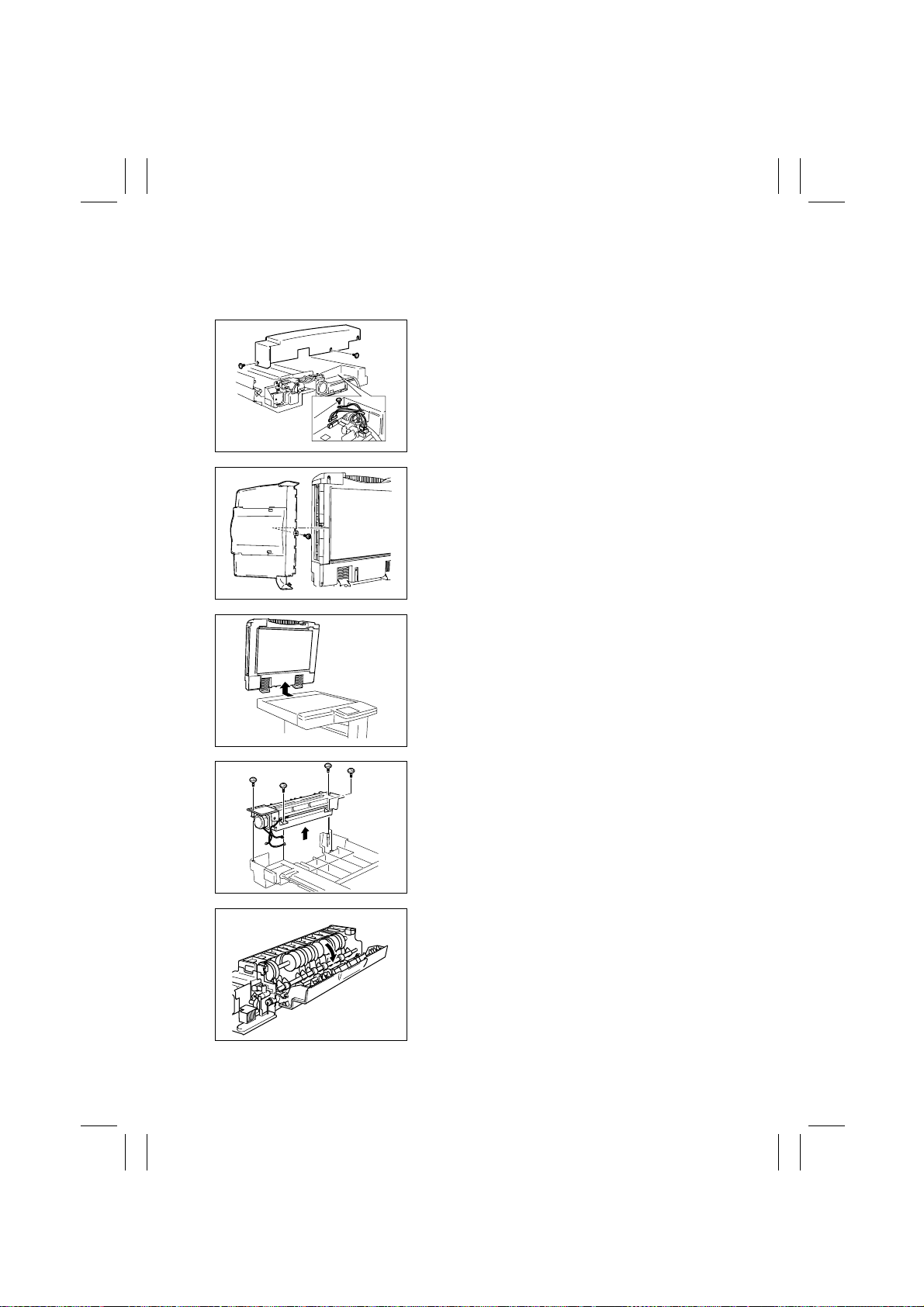
2-7. Adjustment of Turnover/Exit Switching Solenoid SL1
Requirement: The Turnover/Exit Switching Plate should be posit ioned in contact with the rib
on the exit guide plate.
1. Remove two screws shown and the Rear Cover.
2. Unplug the connectors and remove the ground
wire.
4490D022AA
3. Remove one screw shown and the Document
Exit Tray.
4490D023AA
4490D024AB
4490D025AB
4490D026AA
4. Remove the ADF from the copier.
5. Remove the Transport Belt Roller Assy.
(See “2-1. Removal of the Transport Belt.”)
6. Remove the four screws sho wn and the Turnover/
Exit Assy.
7. Open the Exit Cover.
D-10
Page 43
FrameMaker Ver.5.5(PC) AFR-14 OPTION FOR Di350
98.10.09
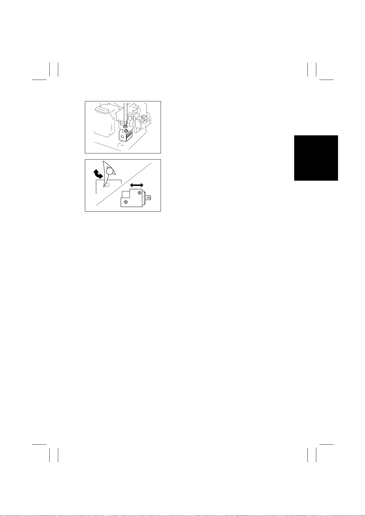
8. Loosen two screws that secure Turnover/Exit
Switching Solenoid.
4490D027AA
9. With Turnover/Exit Switching Solenoid in the
energized position, move the Turnover/Exit
Switching Solenoid body to the right and left to
find a position at which the Turnover/Exit Switching Plate is in contact with the rib on the exit
guide plate. Then, secure Turnover/Exit Switching
Solenoid.
4490D028AB
D-11
Page 44

FrameMaker Ver.5.5(PC) AFR-14 OPTION FOR Di350
98.10.09
TROUBLESHOOTING
General Precautions
1. When servicing the ADF with its covers removed, use utmost care to prevent your
hands, clothing and tools from being caught in moving parts.
2. Before attempting to replace parts and unplugging connectors, make sure that no
power is being supplied from the copier.
3. When creating a closed circuit and measuring a voltage across connector pins specified in the text, be sure to use the green wire (GND).
4. Keep all disassembled parts in good order and keep tools under control so that none
will be lost or damaged.
Reading the Text
1. If a component on a PWB or any other functional unit including a motor is defective, the
text only instructs you to replace the whole PWB or functional unit and does not give
troubleshooting procedure applicable within the defective unit.
2. The text assumes that there are no breaks and shorts in the harnesses and all connectors are plugged into the right positions.
Page 45
FrameMaker Ver.5.5(PC) AFR-14 OPTION FOR Di350
98.10.09
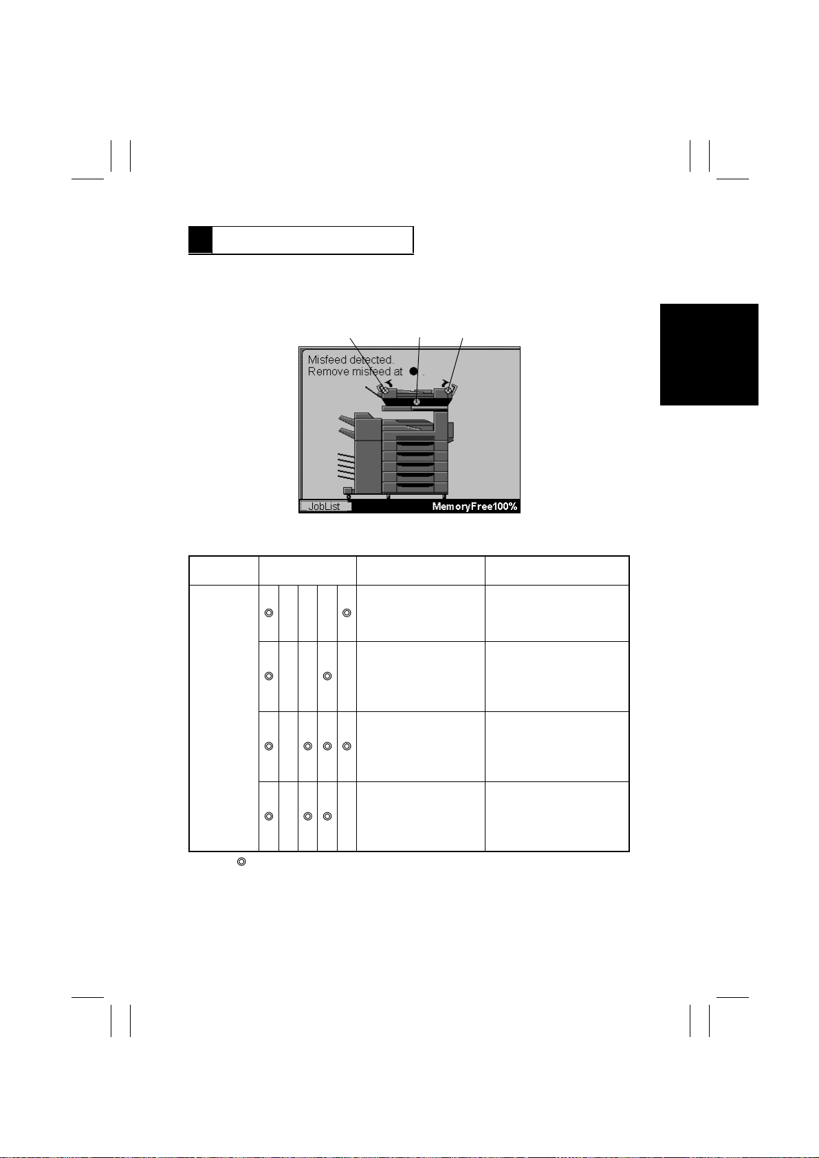
1 MISFEED DETECT ION
•
When a misfeed or malfunction is detected in the ADF, the corresponding code as
detailed below is shown on the copier Touch Panel.
•
In addition, the LEDs on PWB-A of the ADF blink or remain OFF, as detailed below, to
indicate the type of misfeed or malfunction.
BAC
4490S011CA
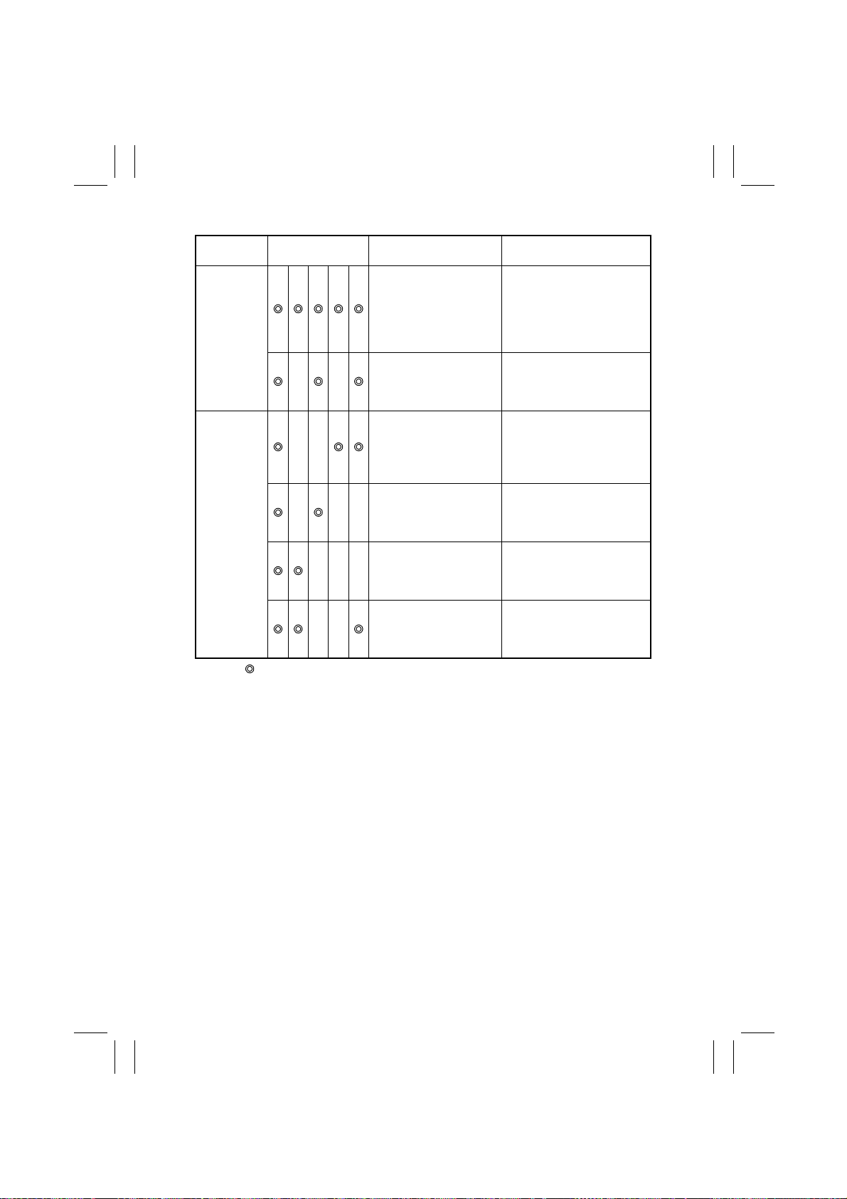
Touch Panel Code, LED Indication, and Detection Timing of Each Misfeed/Malfunction
Touch P anel
Code
A
(Blinking: OFF: ❍)
LED Indication Description Detection Timing
Document not reaching
❍❍❍
❍❍ ❍
❍
❍❍
Registration Sensor PC2
Document staying at
Registration Sensor PC2
Document staying at
Single Feed Empty
Sensor PC9
Pick-Up Motor M1
malfunction
PC2 is not blocked even
after the lapse of 1025
msec. after Take-Up Motor
M2 has been energized.
PC2 is not unblocked even
after the lapse of 1010
msec. after Main Drive
Motor M3 has been energized.
PC9 is not unblocked even
after the lapse of 2125
msec. after Main Drive
Motor M3 has been energized.
Pick-Up Motor Pulse Sensor
PC8 is not blocked or
unblocked even after the
lapse of 1000 msec. after
M1 has been energized.
T-1
Page 46
FrameMaker Ver.5.5(PC) AFR-14 OPTION FOR Di350
98.10.09
Touch P anel
Code
B
C
(Blinking: OFF: ❍)
LED Indication Description Detection Timing
Document left (before
operation is started)
Document left (after
❍❍
❍❍
❍❍❍
❍❍❍
❍❍
operation is started)
Document not reaching
Exit Sensor PC3
Document staying at Exit
Sensor PC3
Document not reaching
Turnover Sensor PC4
Document staying at
Turnover Sensor PC4
When an original is loaded
in the Document Feed Tray
with all closures in the
closed position, a sensor in
the document path is
blocked.
Exit Sensor PC3 is blocked
before the original is positioned after it has been
taken up.
PC3 is not unblocked even
after the lapse of 1205
msec. after Main Drive
Motor M3 has been energized.
PC3 is not blocked even
after the lapse of 1225
msec. after M3 has been
energized.
PC4 is not blocked even
after the lapse of 1215
msec. after M3 has been
energized (to turn forward).
PC4 is not unblocked even
after the lapse of 995 msec.
after M3 has been energized
(to turn backward).
T-2
Page 47
FrameMaker Ver.5.5(PC) AFR-14 OPTION FOR Di350
98.10.09
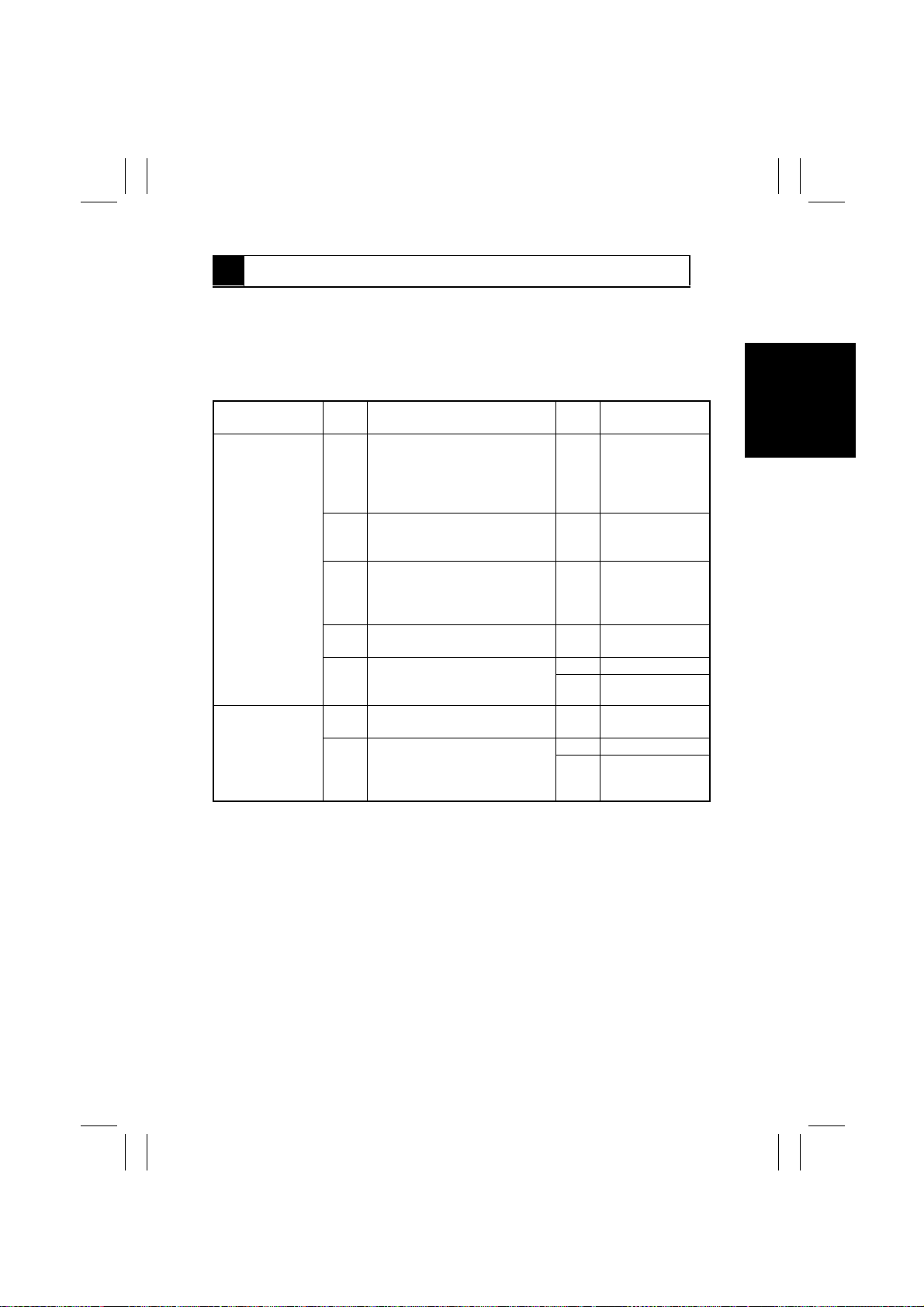
2 MISFEED TROUBLESHOOTING PROCEDURES
1. Check the code shown on the Touch Panel.
2. Check the LED indication to identify the detail of the misfeed.
3. Determine the problem.
4. Perform the check procedures according to the problem.
A. Document Not Reaching Registration Sensor PC2
Problem
•
The original is
not taken up at
all.
•
The original is
stationary
before PC2.
•
The original has
been transported to PC2.
Step
No.
1 Does the document being used
meet the specifications for reliable feeding?
2 Has the capacity of the Docu-
ment Feed Tray been exceeded?
3 Is any of the Take-Up Rolls, Pick-
Up Rolls, or Separator Pads
deformed, worn, or dirty with
paper dust?
4 Are the Pick-Up Rolls pressing
the document?
5 Carry out a unit check of T ake-Up
Motor M2 to determine if it is
operational.
1 Carry out a sensor check of PC2
to determine if it is operational.
2 Does the voltage across PJ9A-11
on PWB-A and GND change
from DC5V to DC0V when PC2 is
blocked with a sheet of paper?
Check Item Result Action
NO Instruct the user to
use the document
that meets the
specifications for
reliable feeding.
YES Instruct the user
not to exceed the
capacity.
YES Clean or replace
the defective part.
NO Check the pick-up
mechanism.
YES Replace PWB-A.
NO Replace M2.
YES Replace PWB-A.
YES Replace PWB-A.
NO Replace PC2.
T-3
Page 48

FrameMaker Ver.5.5(PC) AFR-14 OPTION FOR Di350
98.10.09
B. Document Staying at Registration Sensor PC2
Problem
•
The trailing
edge of the
original is yet to
move past PC2.
•
Two or more
originals are
taken up at
once.
Step
No.
1 Does the document being used
meet the specifications for reliable feeding?
2 Is the Registration Roller
deformed, worn, or dirty?
3 Carry out a unit check of PC2 to
determine if it is operational.
4 Does the voltage across PJ9A-11
on PWB-A and GND change
from DC0V to DC5V when PC2 is
changed from the blocked to
unblocked state with a sheet of
paper?
5 Is the Transport Belt worn or
dirty?
6 Is the Original Glass dirty? YES Clean or replace
7 Carry out a unit check of Main
Drive Motor M3 to determine if it
is operational.
1 Does the document being used
meet the specifications for reliable feeding?
2 Is any of the Take-Up Rolls, Pick-
Up Rolls, or Separator Pads
deformed, worn, or dirty with
paper dust?
Check Item Result Action
NO Instruct the user to
use the document
that meets the
specifications for
reliable feeding.
YES Clean or replace
the Registration
Roller.
YES Go to step 5.
YES Replace PWB-A.
NO Replace PC2.
Clean or replace
YES
the Transport Belt.
the Original Glass.
YES Replace PWB-A.
NO Replace M3.
NO Instruct the user to
use the document
that meets the
specifications for
reliable feeding.
YES Clean or replace
the defective part.
T-4
Page 49
FrameMaker Ver.5.5(PC) AFR-14 OPTION FOR Di350
98.10.09
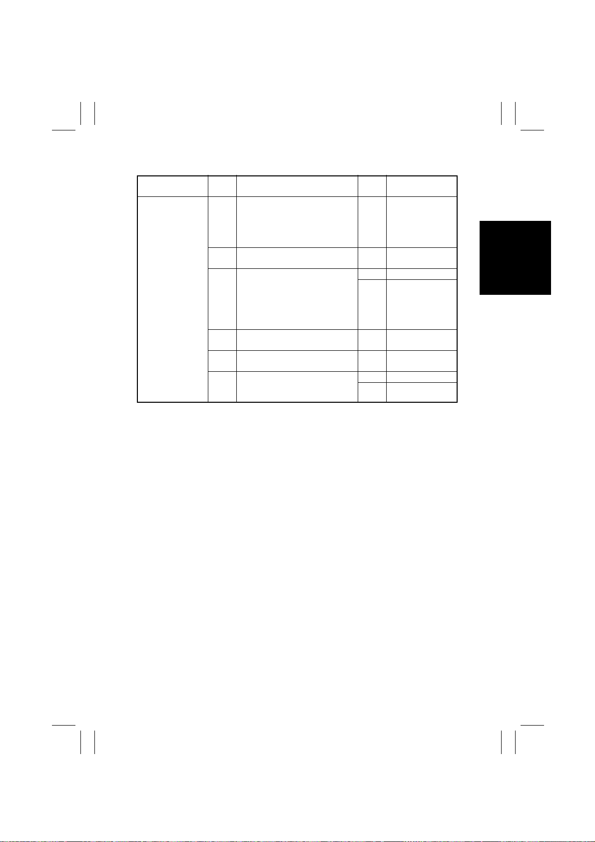
C. Document Staying at Single Feed Empty Sensor PC9
Problem
•
The original is
not taken up at
all.
•
The trailing
edge of the original is yet to
move past PC9.
Step
No.
1 Does the document being used
meet the specifications for reliable feeding?
2 Carry out a unit check of PC9 to
determine if it is operational.
3 Does the voltage across PJ9A-14
on PWB-A and GND change
from DC0V to DC5V when PC9 is
changed from the blocked to
unblocked state with a sheet of
paper?
4 Is the Transport Belt worn or
dirty?
5 Is the Original Glass dirty? YES Clean or replace
6 Carry out a unit check of Main
Drive Motor M3 to determine if it
is operational.
Check Item Result Action
NO Instruct the user to
use the document
that meets the
specifications for
reliable feeding.
YES Go to step 4.
YES Replace PWB-A.
NO Replace PC9.
YES Clean or replace
the Transport Belt.
the Original Glass.
YES Replace PWB-A.
NO Replace M3.
T-5
Page 50
FrameMaker Ver.5.5(PC) AFR-14 OPTION FOR Di350
98.10.09
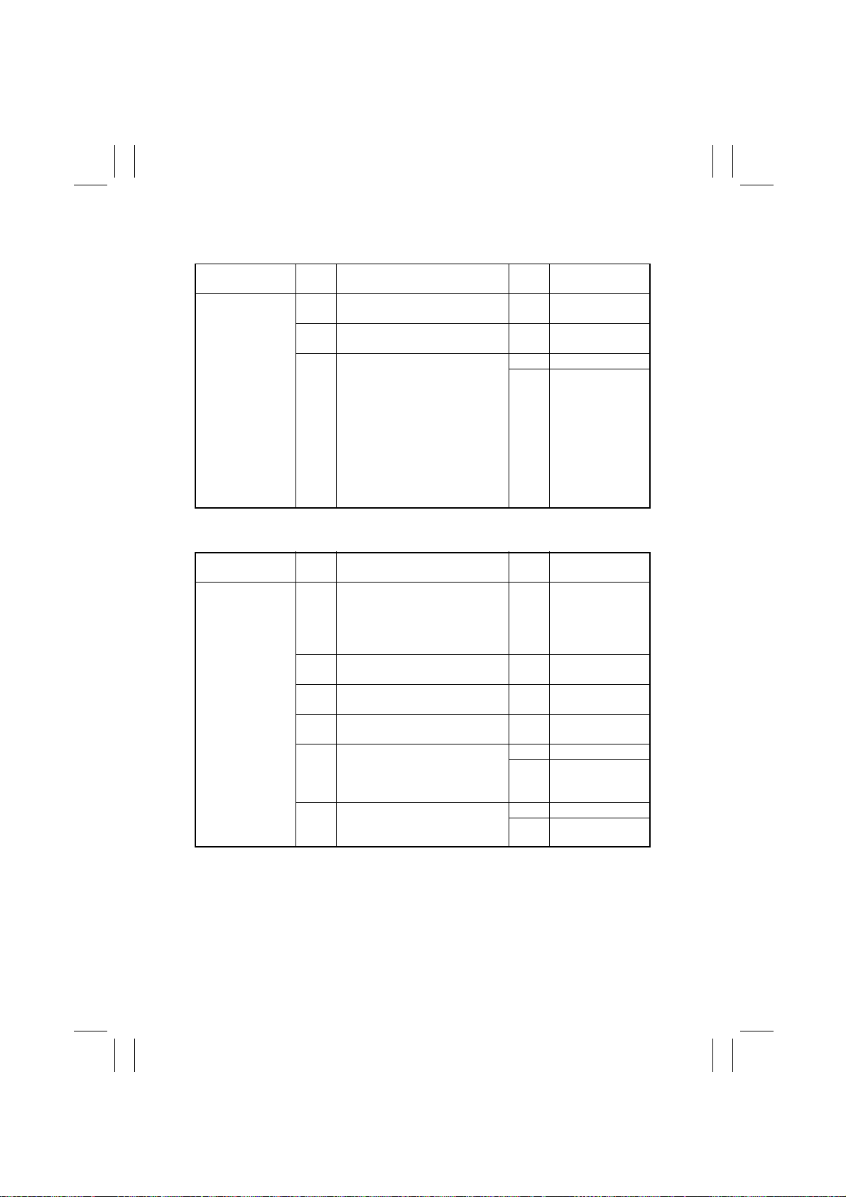
D. Misfeed Detected When Document is Loaded or Immediately After Start Key Has Been
Pressed
Problem
•
An ADF misfeed is displa yed
on the Touch
Panel when a
document is
loaded in the
Document Feed
Tray.
•
An ADF misfeed is displa yed
on the Touch
Panel immediately after the
Start key has
been pressed.
E. Document Not Reaching Exit Sensor PC3
Problem
•
The original is
stationary
before PC3.
Step
No.
1 Is there an original left in the
ADF?
2 If the felt paper of Registration
Sensor PC2 dirty or separated?
3 Carry out a unit check of each
sensor placed along the document path to determine if it is
operational.
Step
No.
1 Does the document being used
meet the specifications for reliable feeding?
2 Is the Transport Belt worn or
dirty?
3 Is the Original Glass dirty? YES Clean or replace
4 Carry out a sensor check of PC3
to determine if it is operational.
5 Does the voltage across PJ11A-2
on PWB-A and GND change
from DC5V to DC0V when PC3 is
blocked with a sheet of paper?
6 Carry out a unit check of Main
Drive Motor M3 to determine if it
is operational.
Check Item Result Action
Check Item Result Action
YES Remove the
original.
YES Clean or replace
the felt paper.
YES Replace PWB-A.
NO Replace the
defective sensor.
NO Instruct the user to
use the document
that meets the
specifications for
reliable feeding.
YES Clean or replace
the Transport Belt.
the Original Glass.
YES Go to step 6.
YES Replace PWB-A.
NO Replace PC3.
YES Replace PWB-A.
NO Replace M3.
T-6
Page 51
FrameMaker Ver.5.5(PC) AFR-14 OPTION FOR Di350
98.10.09
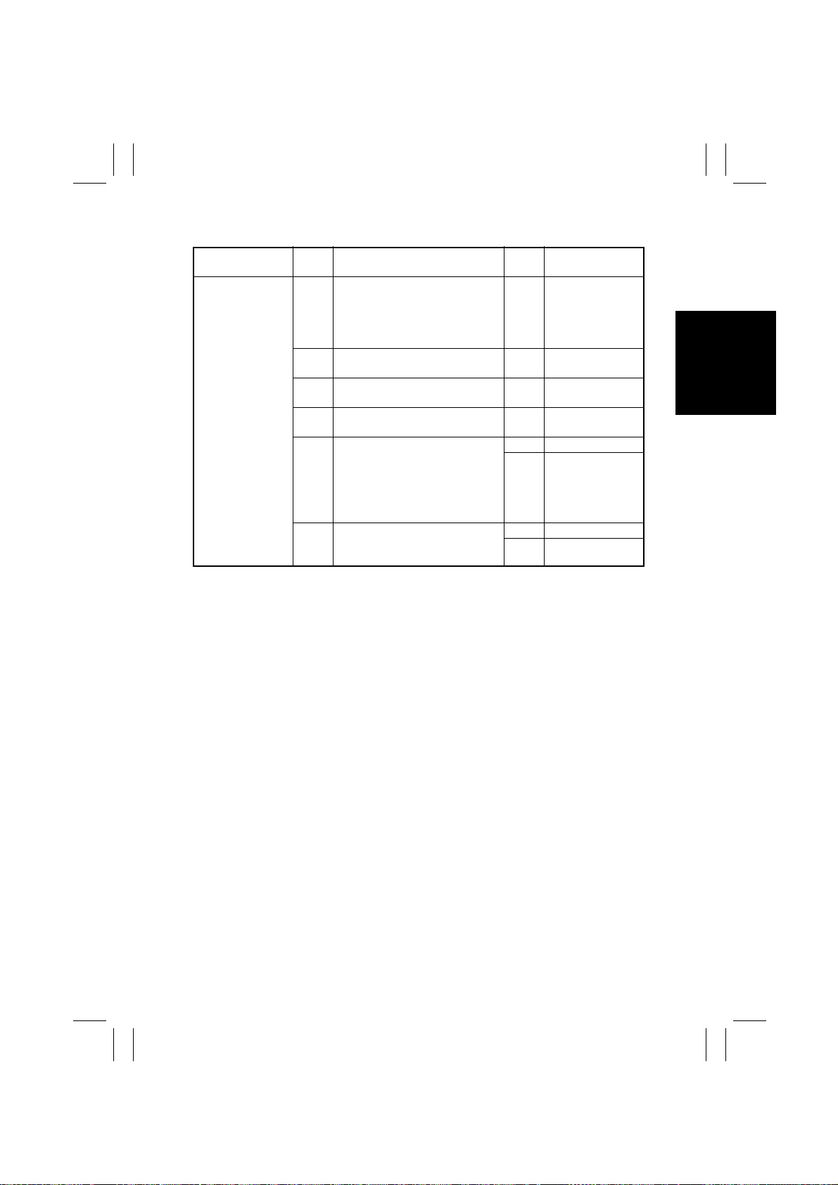
F. Document Staying at Exit Sensor PC3
Problem
•
The trailing
edge of the original is yet to
move past PC3.
Step
No.
1 Does the document being used
meet the specifications for reliable feeding?
2 Is the Transport Belt worn or
dirty?
3 Is the Original Glass dirty? YES Clean or replace
4 Carry out a unit check of PC3 to
determine if it is operational.
5 Does the voltage across PJ11A-2
on PWB-A and GND change
from DC0V to DC5V when PC3 is
changed from the blocked to
unblocked state with a sheet of
paper?
6 Carry out a unit check of Main
Drive Motor M3 to determine if it
is operational.
Check Item Result Action
NO Instruct the user to
use the document
that meets the
specifications for
reliable feeding.
YES Clean or replace
the Transport Belt.
the Original Glass.
YES Go to step 6.
YES Replace PWB-A.
NO Replace PC3.
YES Replace PWB-A.
NO Replace M3.
T-7
Page 52
FrameMaker Ver.5.5(PC) AFR-14 OPTION FOR Di350
98.10.09
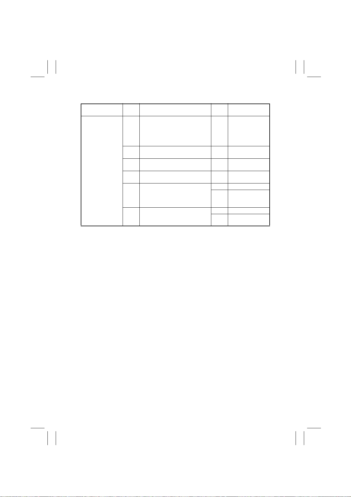
G. Document Not Reaching Turnover Sensor PC4
Problem
•
The original is
stationary
before PC4.
Step
No.
1 Does the document being used
meet the specifications for reliable feeding?
2 Is the Transport Belt worn or
dirty?
3 Is the Original Glass dirty? YES Clean or replace
4 Carry out a sensor check of PC4
to determine if it is operational.
5 Does the voltage across PJ3A-5
on PWB-A and GND change
from DC5V to DC0V when PC4 is
blocked with a sheet of paper?
6 Carry out a unit check of Main
Drive Motor M3 to determine if it
is operational.
Check Item Result Action
NO Instruct the user to
use the document
that meets the
specifications for
reliable feeding.
YES Clean or replace
the Transport Belt.
the Original Glass.
YES Go to step 6.
YES Replace PWB-A.
NO Replace PC4.
YES Replace PWB-A.
NO Replace M3.
T-8
Page 53
FrameMaker Ver.5.5(PC) AFR-14 OPTION FOR Di350
98.10.09
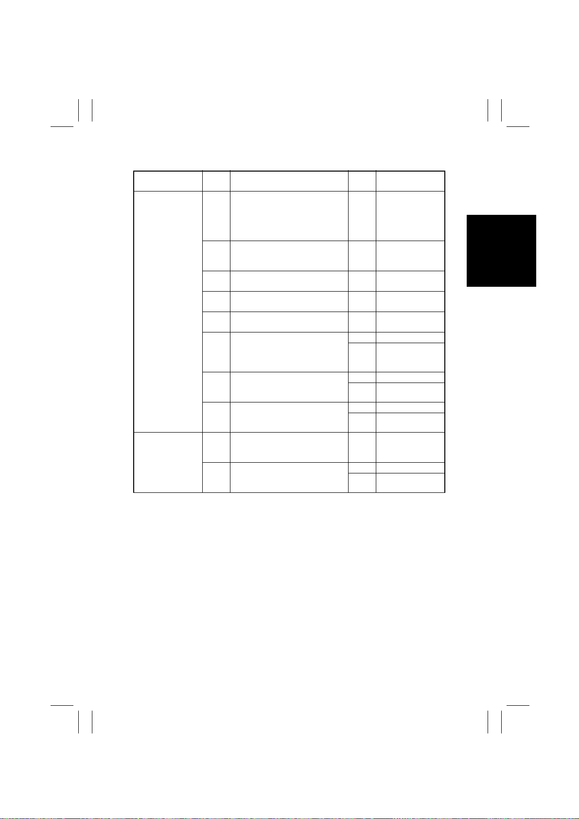
H. Document Staying at Turnover Sensor PC4
Problem
•
The trailing
edge of the original is yet to
move past PC4.
•
An original is
caught by the
Turnover/Exit
Switching Plate.
Step
No.
1 Does the document being used
meet the specifications for reliable feeding?
2 Is the Turnover Roller deformed,
worn, or dirty?
3 Is the Transport Belt worn or
dirty?
4 Is the Original Glass dirty? YES Clean or replace
5 Carry out a sensor check of PC4
to determine if it is operational.
6 Does the voltage across PJ3A-5
on PWB-A and GND change
from DC5V to DC0V when PC4 is
blocked with a sheet of paper?
7 Carry out a unit check of Turn-
over/Exit Motor M4 to determine
if it is operational.
8 Carry out a unit check of Main
Drive Motor M3 to determine if it
is operational.
1 Does the Turnover/Exit Switching
Plate operate abnormally?
2 Carry out a unit check of Turn-
over/Exit Switching Solenoid SL1
to determine if it is operational.
Check Item Result Action
NO Instruct the user to
use the document
that meets the
specifications for
reliable feeding.
YES Clean or replace
the Turnover
Roller.
YES Clean or replace
the Transport Belt.
the Original Glass.
YES Go to step 7.
YES Replace PWB-A.
NO Replace PC4.
YES Replace PWB-A.
NO Replace M4.
YES Replace PWB-A.
NO Replace M3.
YES Replace the Turn-
over/Exit Switching Plate.
YES Replace PWB-A.
NO Replace SL1.
T-9
 Loading...