

Page 1
FrameMaker Ver.5.5(PC) AF-6/AF-7 OPTION FOR Di350
98.11.09
AF-6/AF-7
SERVICE MANUAL
14413
Page 2

FrameMaker Ver.5.5(PC) AF-6/AF-7 OPTION FOR Di350
98.11.09
CONTENTS
GENERAL, MECHANICAL/ELECTRICAL
1. SPECIFICATIONS ........................................................................................... M-1
2. COMPONENTS IDENTIFICATION .................................................................M-2
3. CROSS-SECTIONAL VIEW ............................................................................M-3
4. DRIVE SYSTEM ..............................................................................................M-4
5. ELECTRICAL COMPONENT LAYOUT ...........................................................M-5
6. DESCRIPTION OF MODES ............................................ ........................... .....M-6
6-1. 1-Sided Original Mode .............................................................................M-6
6-2. Mixed Original Mode ................................................................................M-6
7. DOCUMENT TAKE-UP/FEEDING MECHANISM ............................................M-7
7-1. Document Take-Up Mechanism ..............................................................M-7
7-2. Document Separating Mechanism ...........................................................M-8
8. DOCUMENT TRANSPORT/EXIT MECHANISM .............................................M-9
8-1. Document Transport Mechanism .............................................................M-9
8-2. Document Exit Mechanism ......................................................................M-9
8-3. Document Size Detection ........................................................................ M-10
8-4. Raised/Lowered Position Detection Mechanism .....................................M-10
TECH. REP. MODE
1. OUTLINE OF THE TECH. REP. MODE ..........................................................S-1
2. SENSOR CHECK .................... ........................... ........................... ..................S-1
DIS/REASSEMBLY, ADJUSTMENT
1. DISASSEMBLY ...............................................................................................D-1
1-1. Removal of the Exterior Covers ...............................................................D-1
1-2. Removal of the Scanner Unit ...................................................................D-1
1-3. Removal of the Separator Roller Assy .....................................................D-2
2. ADJUSTMENT .................................................................................................D-3
2-1. Adjustment of the Scanning Start Position in the Main/Sub
Scanning Direction ...................................................................................D-3
2-2. Adjustment of the Scanning Zoom Ratio in the Main/Sub
Scanning Direction ...................................................................................D-4
TROUBLESHOOTING
1. MISFEED TROUBLESHOOTING PROCEDURES .............................. ...........T-1
i
Page 3

FrameMaker Ver.5.5(PC) AF-6/AF-7 OPTION FOR Di350
98.11.09
GENERAL,
MECHANICAL/ELECTRICAL
Page 4
FrameMaker Ver.5.5(PC) AF-6/AF-7 OPTION FOR Di350
98.11.09
1 SPECIFICATIONS
Name : Automatic Document Feeder
Installation : Screwed to the copier
Type of Document : Plain paper
Detectable Document
Sizes
Capacity : 70 sheets max. (50 sheets max when Mix Original Mode):
Alignment : Rear Document Edge Guide
Document Loading : Face up
Document Exchange
Speed
Modes : 1-Sided Original
Power Source : DC24V, DC5V (supplied from the copier)
Power Consumption : 80.7W
Dimensions : Width 538 mm or 21-1/4”
Weight : 6.0 kg or 13-1/4” lbs
Operating Environment : Same as copier
Originals Which Should
Not be Used
: Metric Areas: A5L/C, A4L/C, B5L/C, A3L, Foolscap
Inch Areas: 5-1/2”×8-1/2”L/C, 8-1/2”×11”L/C, 8-1/2”×14”L,
11"×17”L, 10-1/8”×14”L
52.3~81.4 g/m
: AF-6: 18 sheets/min., 25 sheets/min. (A4C or 8-1/2”×11”
C)
AF-7: 35 sheets/min. (A4C or 8-1/2”×11” C)
Mixed Original (set with User’s Choice of the copier)
Depth 497 mm or 19-1/2”
Height 97 mm or 3-3/4”
(excluding Document Loading Tray)
:
2
Type of Original Possible Trouble
Sheets stapled or clipped together Take-up failure, damaged sheet, defective
Sheets glued together Take-up failure, damaged sheet
Sheets folded, torn, or wrinkled Take-up failure, damaged sheet
Sheets severely curled Sheets misfed due to being dog-eared or fed
drive mechanism due to jammed clips.
in askew
M-1
Page 5
FrameMaker Ver.5.5(PC) AF-6/AF-7 OPTION FOR Di350
98.11.09
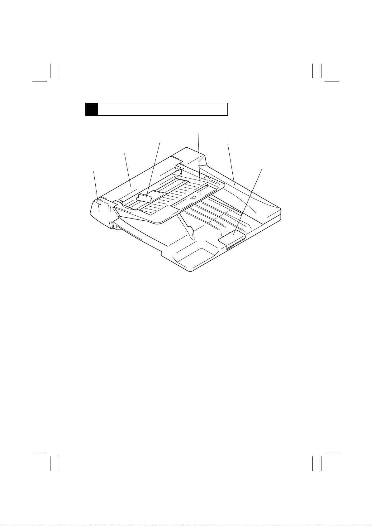
2 COMPONENTS IDENTIFICA TI ON
4
3
2
5
1
1. Front Cover
2. Take-Up Cover
3. Document Edge Guide
6
4490D001AA
4. Document Loading Tray
5. Rear Cover
6. Stopper
M-2
Page 6
FrameMaker Ver.5.5(PC) AF-6/AF-7 OPTION FOR Di350
98.11.09
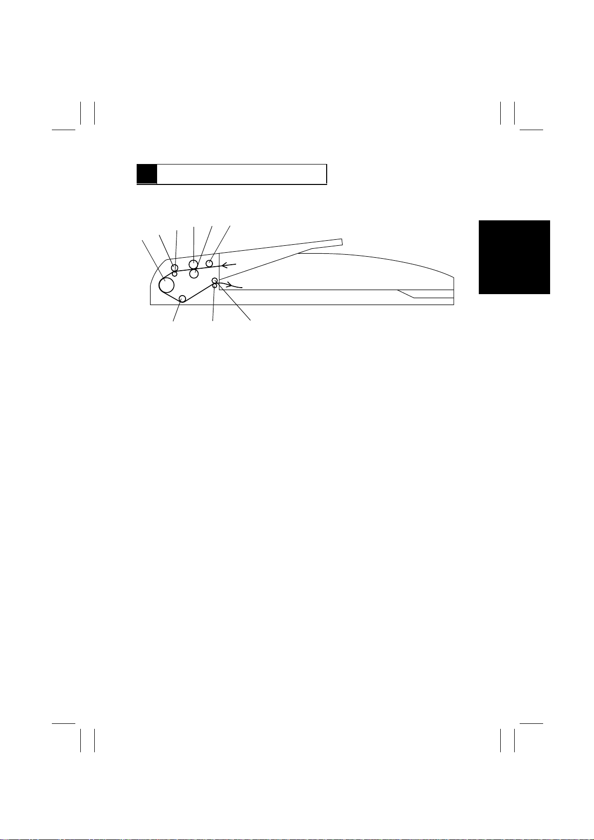
3 CROSS-SECTIONAL VIEW
6
5
4
3
2
1
1. Turnover Roller
2. Feed Roller
3. Feed Roll
4. Take-Up Roller
5. Separator Roller
789
6. Auxiliary Roller
7. Exit Roller
8. Exit Roll
9. Document Scanning Position Roller
4490D002AA
M-3
Page 7
FrameMaker Ver.5.5(PC) AF-6/AF-7 OPTION FOR Di350
98.11.09
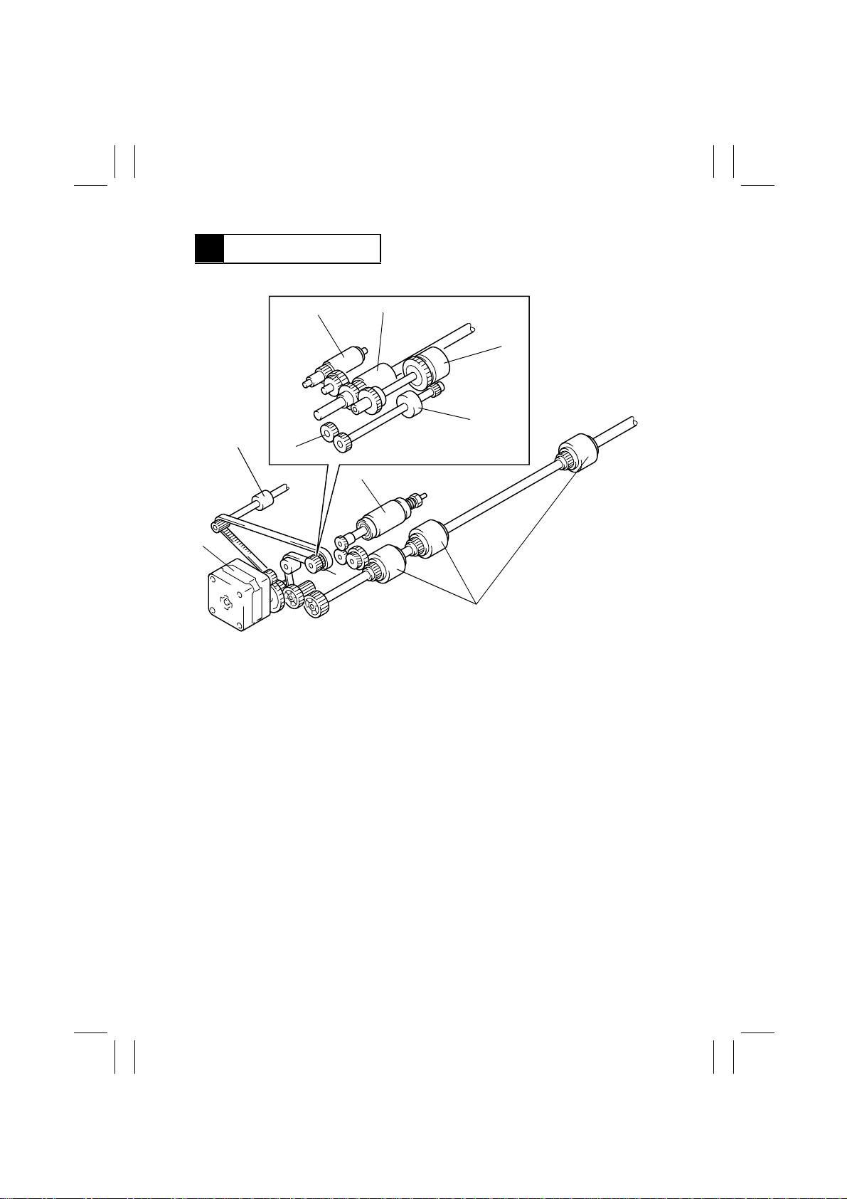
4 DRIVE SYSTEM
2
1
1. Main Motor
2. Exit Roller
3. Separator Roller
4. Turnover Roller
A
5
A
6
7
8
3
4
4490D003AB
5. Auxiliary Roller
6. Take-Up Roller
7. Take-Up Clutch
8. Feed Roller
M-4
Page 8
FrameMaker Ver.5.5(PC) AF-6/AF-7 OPTION FOR Di350
98.11.09
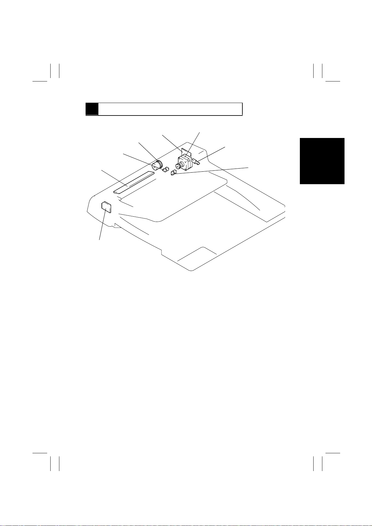
5 ELECTRICAL COMPONENT LAYOUT
4
3
2
1
1. Print Lamp Board
2. Original Size Detecting Board
3. Registration Sensor
4. Take-Up Clutch
5
6
7
8
4490D004AB
5. ACR Board
6. Main Motor
7. Cover Switch
8. Document Empty Sensor
M-5
Page 9

FrameMaker Ver.5.5(PC) AF-6/AF-7 OPTION FOR Di350
98.11.09
6 DESCRIPTION OF MODES
6-1. 1-Sided Original Mode
•
When a multi-page document is being used, the copier detects the size of only the first
page of the document and runs for the subsequent pages based on that size detection.
•
The mode is used when making copies of a document set consisting of pages of the
same size.
6-2. Mixed Original Mode
•
The copier detects the size of each page of the document as it is taken up and fed in and,
according to the size detected, feeds the copy paper of the corresponding size selected
from among the available paper sources.
•
The width of the pages of the document must be the same.
•
This mode is used when making copies from a document set consisting of pages of different sizes from each other. (This setting is made with User’s Choice of the copier.)
M-6
Page 10
FrameMaker Ver.5.5(PC) AF-6/AF-7 OPTION FOR Di350
98.11.09
7 DOCUMENT TAKE-UP/FEEDING MECHANISM
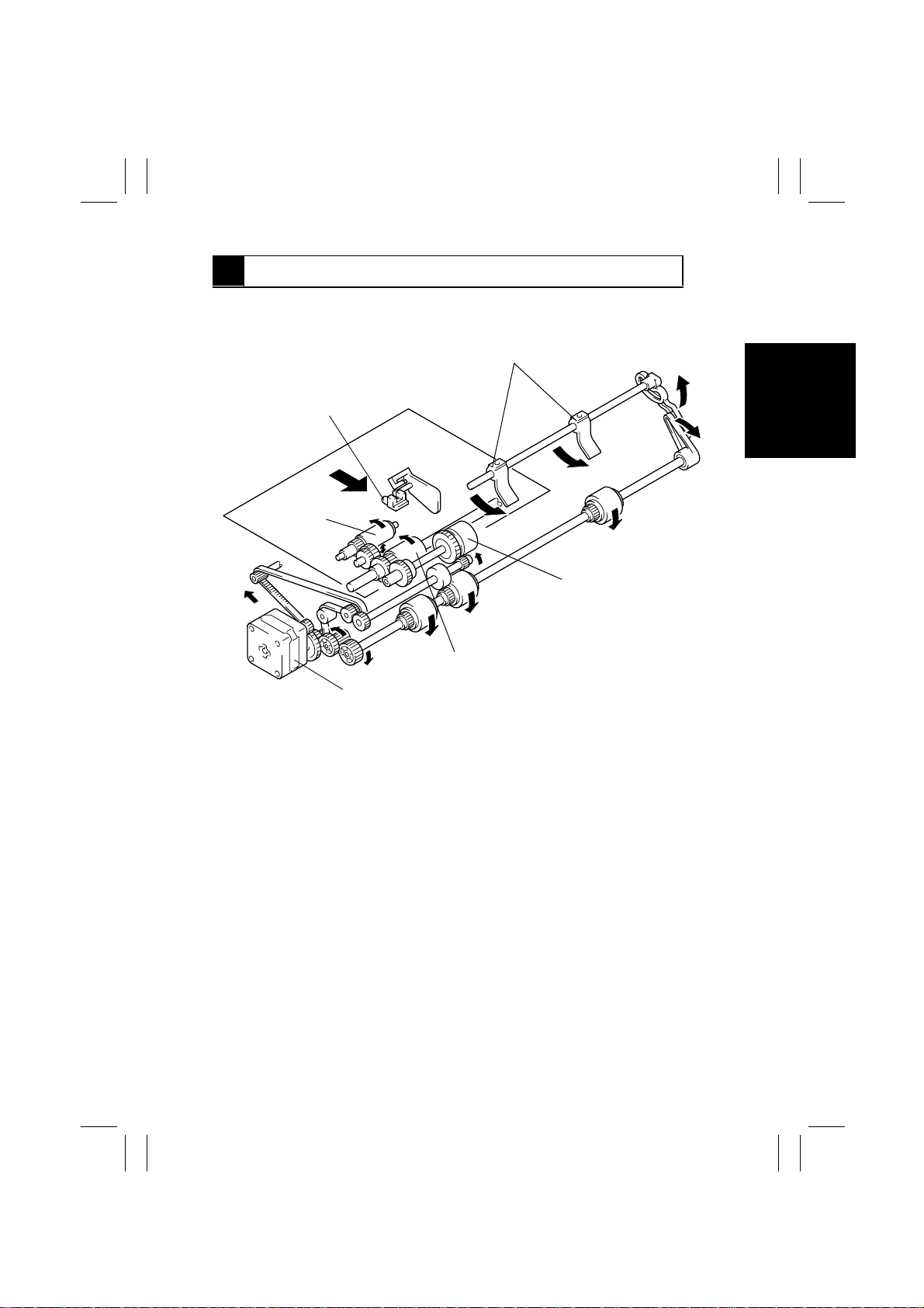
7-1. Document Take-Up Mechanism
Document Stoppers
Document Empty Sensor
Auxiliary Roller
Take-Up Clutch
Take-Up Roller
Main Motor
•
The document is taken up as the Auxiliary Roller and Take-Up Roller turn.
•
The Auxiliary Roller transports the document up to the Take-Up Roller, moving up and
down at all times during a document take-up sequence.
•
The Auxiliary Roller and Take-Up Roller are turned through the Take-Up Clutch and by
gears driven by the Main Motor.
•
The Document Empty Sensor is used to detect a document loaded on the Document
Loading Tray.
•
The leading edge of the document is determined by the Document Stoppers. They s wing
upward when the document is taken up and are in the lowered, swung-down position in
the standby state.
•
The Document Stoppers are swung up or down by the Main Motor that turns forward (to
swing them up) or backward (to swing them down).
4490D005AC
M-7
Page 11
FrameMaker Ver.5.5(PC) AF-6/AF-7 OPTION FOR Di350
98.11.09
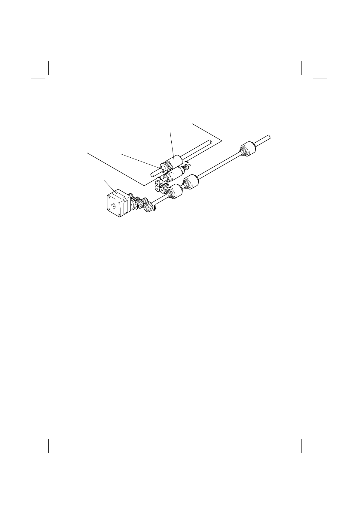
7-2. Document Separating Mechanism
Take-Up Roller
Separator Roller
Main Motor
4490D006AB
•
The Separator Roller is turned in the direction opposite to that of the Take-Up Roller,
which effectively separates the top page of the document from the rest.
•
The Separator Roller is turned by gears driven by the Main Motor.
M-8
Page 12
FrameMaker Ver.5.5(PC) AF-6/AF-7 OPTION FOR Di350
98.11.09
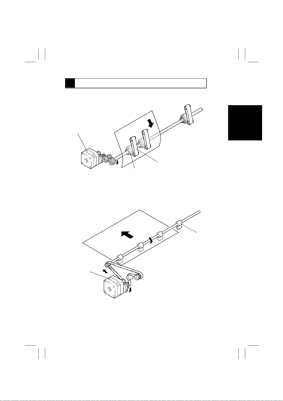
8 DOCUMENT TRANSPORT/EXIT MECHANISM
8-1. Document Transport Mechanism
Main Motor
Turnover Belt
Turnover Roller
•
The document taken up is transported to the document scanning position of the copier by
the Turnover Roller and Turnover Belt.
•
The Turnover Roller and Turnover Belt are driven by gears which are driven by the Main
Motor.
4490D047AA
8-2. Document Exit Mechanism
Exit Roller
Main Motor
4490D048AA
•
The document is fed out of the ADF by the Exit Roller.
•
The Exit Roller is driven by gears and a belt which are driven by the Main Motor.
M-9
Page 13
FrameMaker Ver.5.5(PC) AF-6/AF-7 OPTION FOR Di350
98.11.09
8-3. Document Size Detection
•
The document size is determined by means of two different systems of document width
detection and document length detection.
(Document Width Detection)
•
The width of an original is determined by the combination of the block ed (L) and
unblocked (H) states of the Original Size Detecting Sensors (1 to 5), as detected while
the original is being taken up.
(Document Length Detection)
•
The length of an original is determined as the leading or trailing edge of the original
blocks (L) or unblocks (H) the Registration Sensor.
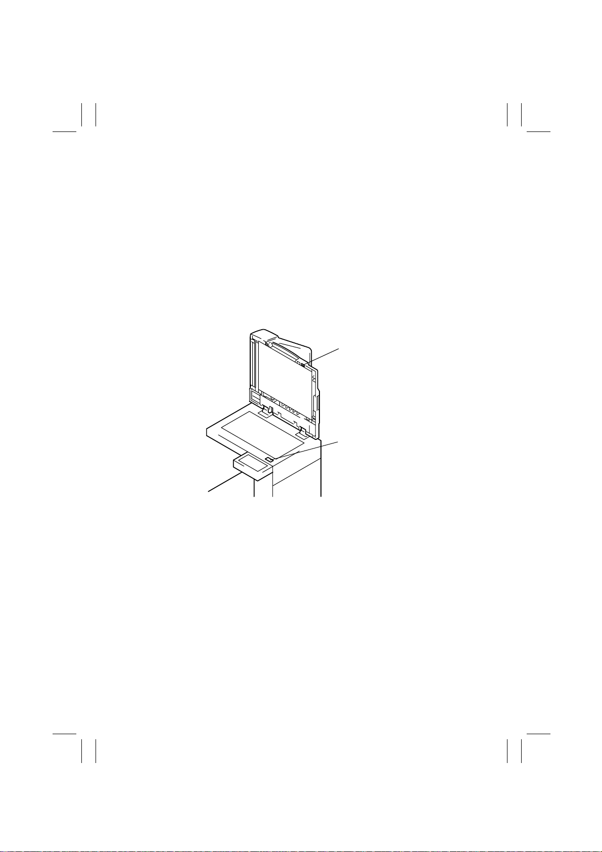
8-4. Raised/Lowered Position Detection Mechanism
Magnet
Size Reset Switch S5
4490D009AA
•
There is a magnet installed in the ADF body to allow the copier to know that the ADF is
raised or lowered.
•
This magnet actuates and deactuates the Size Reset Switch on the copier.
M-10
Page 14

FrameMaker Ver.5.5(PC) AF-6/AF-7 OPTION FOR Di350
98.11.09
TECH. REP. MODE
Page 15
FrameMaker Ver.5.5(PC) AF-6/AF-7 OPTION FOR Di350
98.11.09
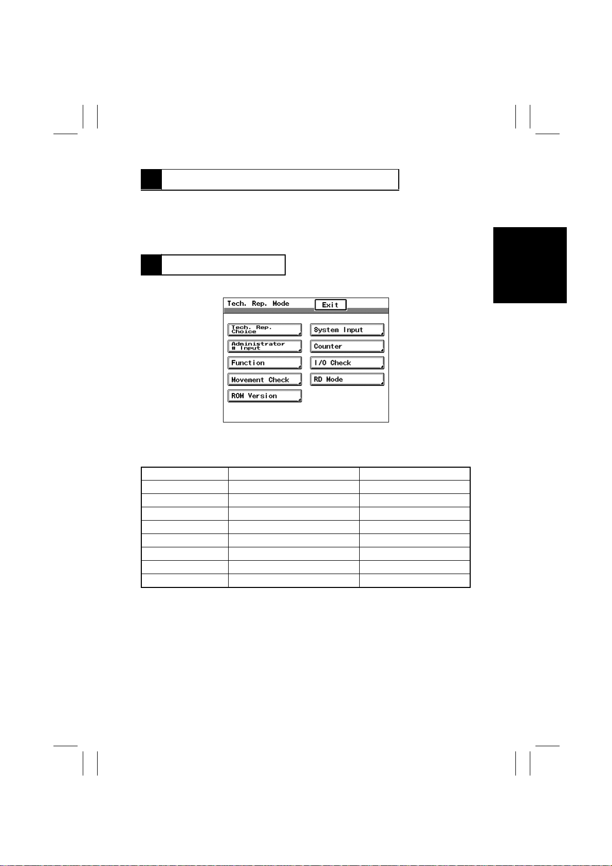
1 OUTLINE OF THE TECH. REP. MODE
•
The Tech. Rep. mode off ered by the copier permits sensor checks.
•
Sensor checks (I/O Check) are mainly made as part of troubleshooting procedures.
•
For the steps to access the “Tech. Rep. Mode” menu, see SWITCHES ON PWBs/TECH.
REP. MODE of the copier’s Service Manual.
2 SENSOR CHECK
1. Select the function as follows: Tech. Rep. Mode → I/O Check.
1166U043CA
2. Select “Scan-through ADF.”
3. Using a sheet of paper, activate the sensor to be checked and check f or the display on
the screen.
Screen Display Sensor Name On-screen Data
S1 Cover Switch
S2 Document Empty Sensor
S3 Registration Sensor
S4 Original Size Detecting Sensor 1
S5 Original Size Detecting Sensor 2
S6 Original Size Detecting Sensor 3
S7 Original Size Detecting Sensor 4
S8 Original Size Detecting Sensor 5
Closed: 0
Paper present: 1
Paper present: 1
Paper present: 1
Paper present: 1
Paper present: 1
Paper present: 1
Paper present: 1
S-1
Page 16

FrameMaker Ver.5.5(PC) AF-6/AF-7 OPTION FOR Di350
98.11.09
DIS/REASSEMBLY,
ADJUSTMENT
Precautions for Disassembly, Reassembly, and Adjustment
1. Before attempting to disassemble the ADF, always make sure that no power is being
supplied from the copier.
2. While power is being supplied to the ADF, do not attempt to remove/install the print
jacks or unplug/plug in the connectors.
3. If the ADF is run with its covers removed, use care not to allow your clothing to be
caught in the belt or other revolving part.
4. The basic rule is do not run the ADF with any of its parts removed.
5. A toothed washer is used with the screw that secures the ground wire to ensure positive
conduction. Do not forget to use this washer at reassembly.
6. To reassemble the ADF, reverse the order of disassembly unless otherwise specified.
7. Do not attempt to remove or loosen the screws to which red paint has been applied.
Purpose of Application of Red Paint
Red paint is applied to the screws of parts that cannot be readjusted, set, or reinstalled in
the field.
Page 17
FrameMaker Ver.5.5(PC) AF-6/AF-7 OPTION FOR Di350
98.11.09
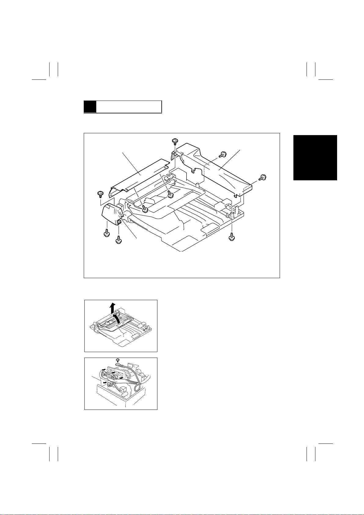
1 DISASSEMBLY
1-1. Removal of the Exterior Covers
Take-Up Cover
Front Cover
1. Take-Up Cover: Two screws, two tabs
2. Rear Cover: Four screws, two tabs
3. Front Cover: Three screws
1-2. Removal of the Scanner Unit
1. Remove the Document Loading Tray.
Rear Cover
4490D010AA
4490D011AA
4490D012AA
2. Unplug four connectors from the PWB.
3. Remove one screw and ground wire.
D-1
Page 18
FrameMaker Ver.5.5(PC) AF-6/AF-7 OPTION FOR Di350
98.11.09
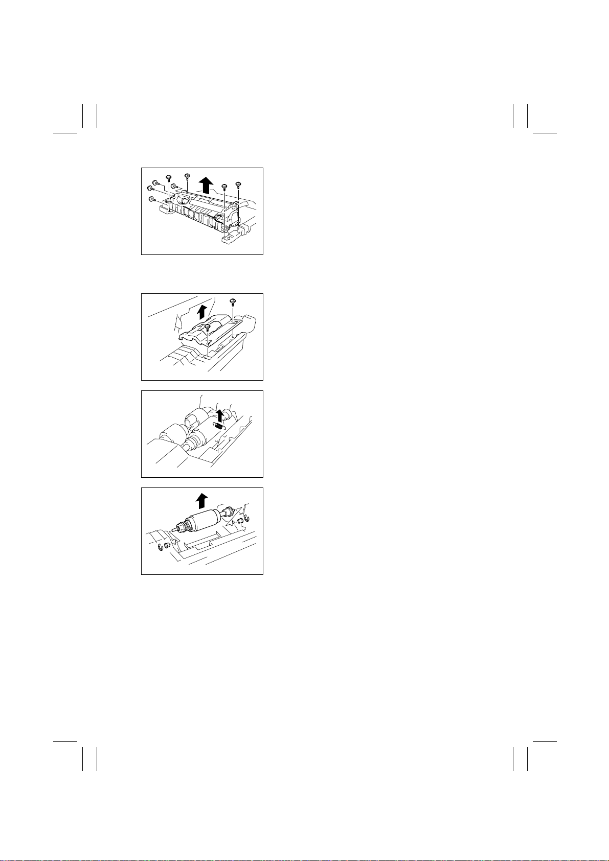
4. Remove eight screws and the Scanner Unit.
4490D013AA
1-3. Removal of the Separator Roller Assy
1. Remove the Separator Cover.
4490D014AA
2. Unhook the spring.
4490D015AA
4490D016AA
3. Snap off the E-rings and remove the bushings.
4. Remove the Separator Roller Assy.
D-2
Page 19
FrameMaker Ver.5.5(PC) AF-6/AF-7 OPTION FOR Di350
98.11.09
2 ADJUSTMENT
2-1. Adjustment of the Scanning Start Position in the Main/Sub
Scanning Direction
(To be adjusted after scanning zoom ratio adjustment)
(Requirement: The allowance with respect to the reference line should be Main Scanning
Direction ±10%, Sub Scanning Direction ±15%.)
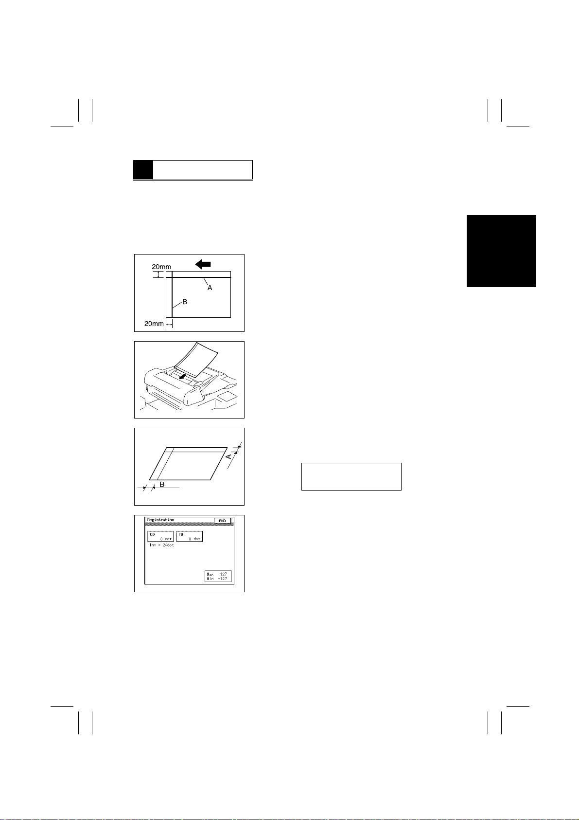
1. Prepare a test chart (A3) as shown.
✽
Draw a straight line at a point 20 mm from the top
edge (A): Main scanning direction.
✽
Draw a straight line at a point 20 mm from the left
edge (B): Sub scanning direction.
4490D017AA
2. Make a full-size copy of the test chart.
1166U016AA
1166U015AB
1166U046CA
3. Using a scale, measure the dimensions between
the corresponding edge and line and determine the
deviation.
A: 20 ±2.0 mm
B: 20 ±3.0 mm
4. Select the function as follows: Tech. Rep. Mode
Tech. Rep. Choice → Scan-through ADF → Registration.
D-3
→
Page 20
FrameMaker Ver.5.5(PC) AF-6/AF-7 OPTION FOR Di350
END
98.11.09
5. Follow these steps to adjust the deviation.
A. Select CD or FD.
B. Blank out the numeric value with the Clear key.
C. Switch the + or - sign as necessary with the key.
(Select - if the dimension is longer and + if it is
shorter.)
D. Enter the numeric value from the 10-Key Pad.
1166U038AA
(1 mm = 24 dots)
E. Touch .
F. Make a copy again and check for deviation.
2-2. Adjustment of the Scanning Zoom Ratio in the Main/Sub
Scanning Direction
(Requirement: The allowance with respect to the reference line should be Main Scanning
Direction ±1.0%, Sub Scanning Direction ±1.5%.)
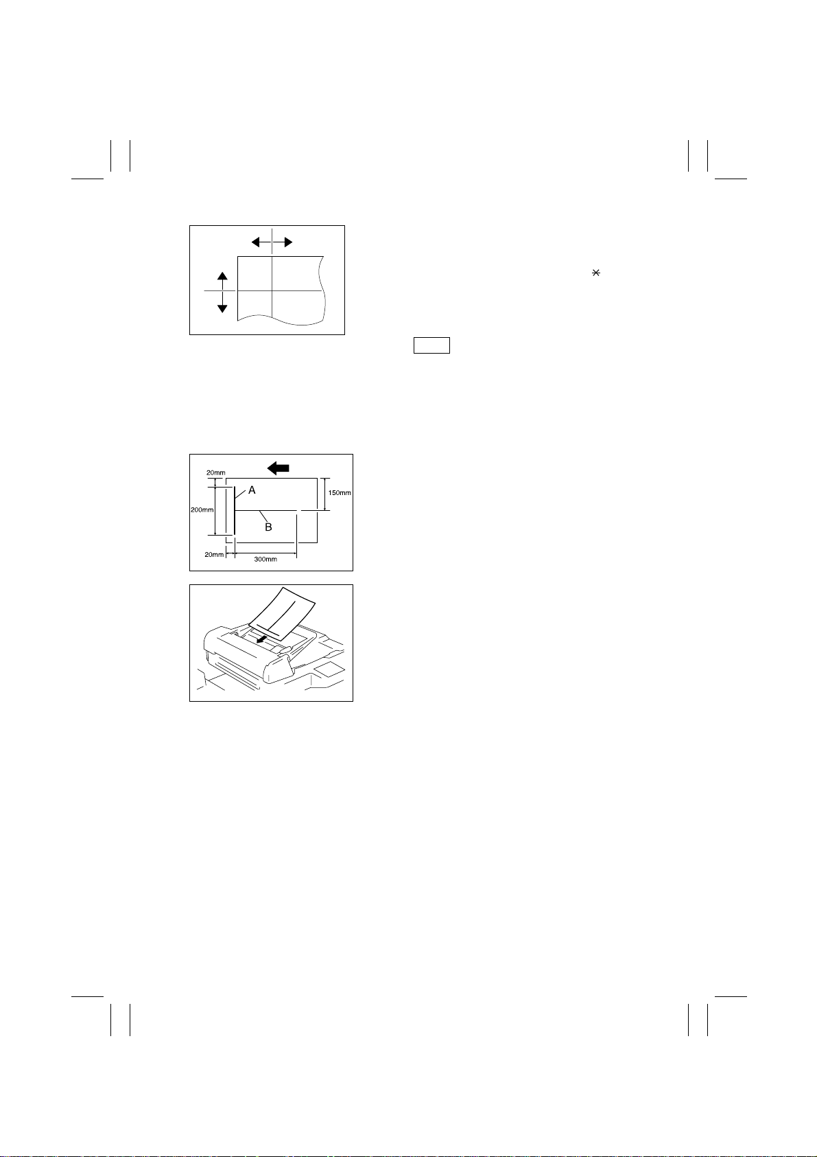
1. Prepare a test chart (A3) as shown.
✽
Draw a 200-mm-long straight line starting with a
point 20 mm from the left edge and 20 mm from the
top edge (A): Main scanning direction.
✽
Draw a 300-mm-long straight line starting with a
point 20 mm from the left edge and 150 mm from the
top edge (B): Sub scanning direction.
4490D018AA
1166U052AA
2. Make a full-size copy of the test chart.
D-4
Page 21
FrameMaker Ver.5.5(PC) AF-6/AF-7 OPTION FOR Di350
END
98.11.09
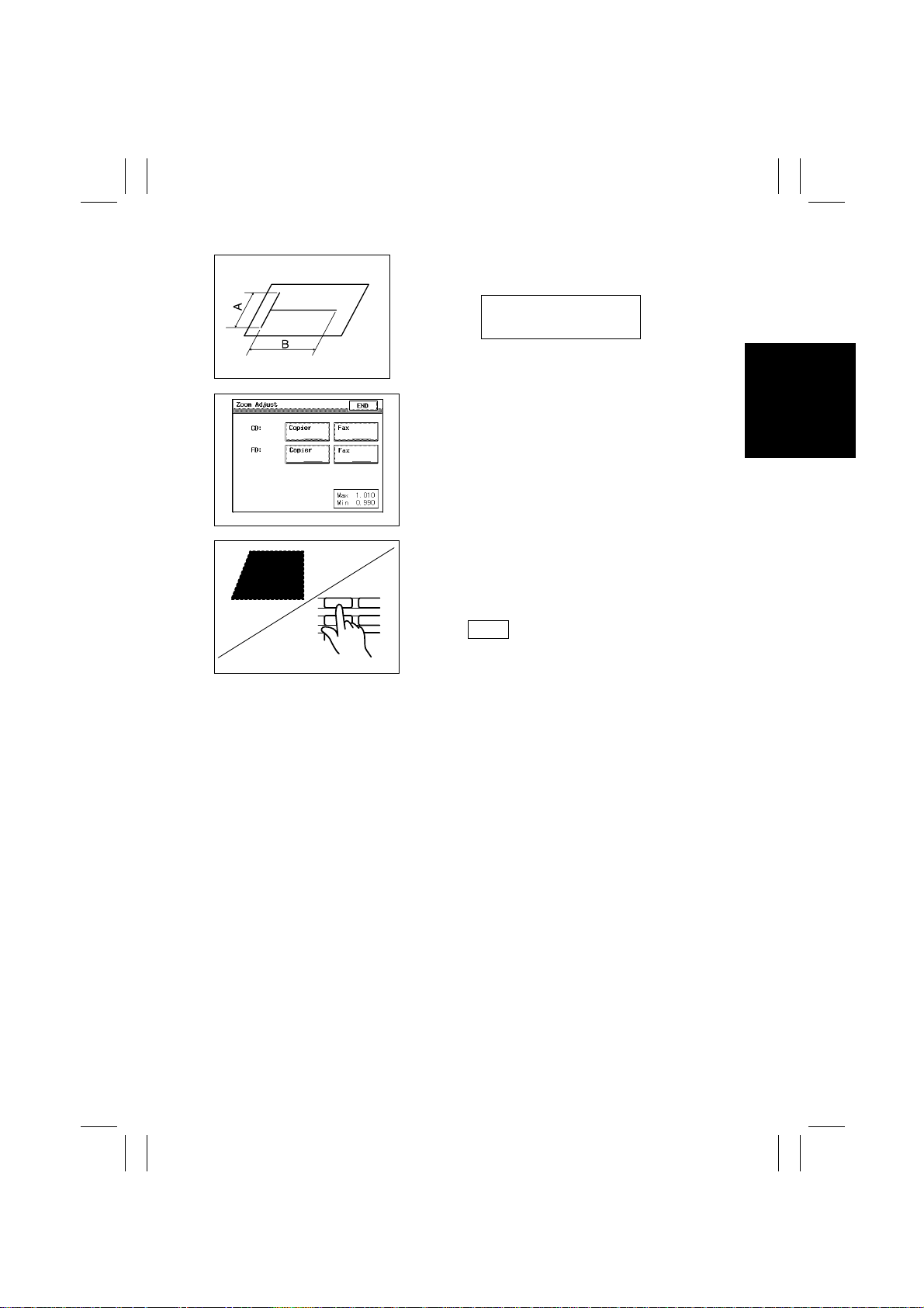
3. Using a scale, measure the dimensions of the lines
A and B and determine the deviation.
1166U051AA
4. Select the function as follows: Tech. Rep. Mode →
Tech. Rep. Choice → Scan-through ADF → Zoom
Adjust.
1166U048CA
5. Follow these steps to adjust the deviation.
A. Select CD “Copier” or FD “Copier.”
B. Blank out the numeric value with the Clear key.
1.001
2
1
5
4
C. Enter the numeric value (zoom ratio) from the 10-
Key Pad. (×1.010 to ×0.990)
D. Touch .
E. Make a copy again and check for deviation.
1166U050AA
A: 200 ±2.0 mm
B: 300 ±4.5 mm
D-5
Page 22

FrameMaker Ver.5.5(PC) AF-6/AF-7 OPTION FOR Di350
98.11.09
TROUBLESHOOTING
General Precautions
1. When servicing the ADF with its covers removed, use utmost care to prevent your
hands, clothing and tools from being caught in revolving parts.
2. Before attempting to replace parts and unplugging connectors, make sure that no
power is being supplied from the copier.
3. When creating a closed circuit and measuring a voltage across connector pins specified in the text, be sure to use the green wire (GND).
4. Keep all disassembled parts in good order and keep tools under control so that none
will be lost or damaged.
Reading the Text
1. If a component on a PWB or any other functional unit including a motor is defective, the
text only instructs you to replace the whole PWB or functional unit and does not give
troubleshooting procedure applicable within the defective unit.
2. The text assumes that there are no breaks and shorts in the harnesses and all connectors are plugged into the right positions.
Page 23
FrameMaker Ver.5.5(PC) AF-6/AF-7 OPTION FOR Di350
98.11.09
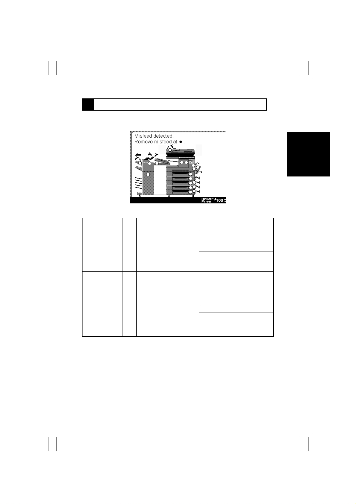
1 MISFEED TROUBLESHOOTING PROCEDURES
•
When a misfeed is detected, the Touch Panel of the copier gives a display as shown
➃
below (
).
4
6
10
7
8
9
5
11
13
12
14
15
16
17
18
19
20
21
4490T001CA
Symptom
•
The document
is not properly
detected when
it is loaded.
•
The document
is not taken up
at all.
Step
No.
Check Item Result Action
1 Is the Document Empty
Sensor operational, as
checked through a sensor
check?
1 Does the Auxiliary Roller
press the document?
2 Is the Main Motor ener-
gized?
3 Does the voltage across
CN3-1 on the ACR Board
and GND change from LOW
to HIGH when the Start key
is pressed?
YES Change the ACR Board,
HGB Board, and MFB
Board, in that order.
NO Check the actuator for
operation and, if it is
intact, change the sensor.
NO Check the drive transmit-
ting gears.
YES Check the drive transmit-
ting gears up to the TakeUp Roller.
YES Change the Main Motor.
NO Change the ACR Board,
HGB Board, and MFB
Board, in that order.
T-1
Page 24
FrameMaker Ver.5.5(PC) AF-6/AF-7 OPTION FOR Di350
98.11.09
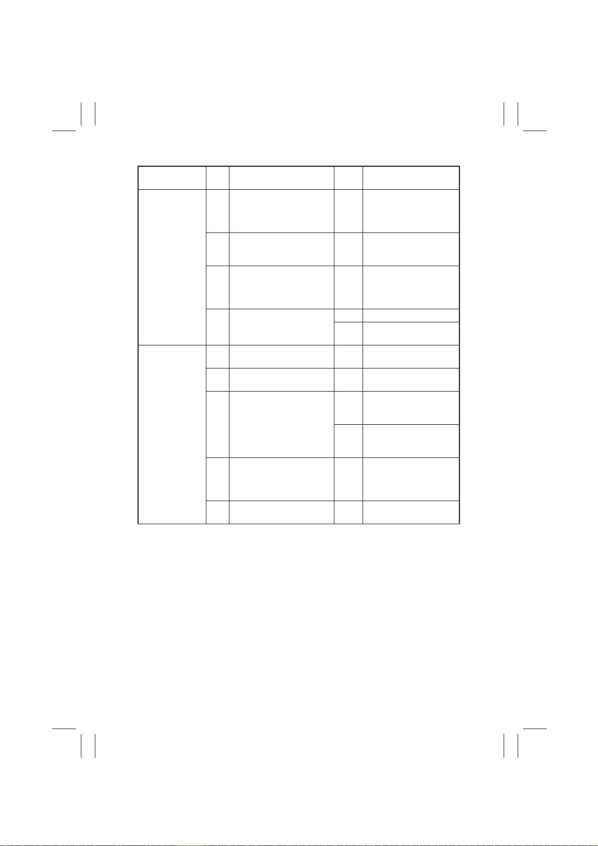
Symptom
•
Multiple feed of
document
pages occurs.
•
The document
stops midway.
Step
No.
1 Does the document being
used fall outside the category of reliable feeding?
2 Has the capacity of the Doc-
ument Loading Tray been
exceeded?
3 Is any of the Auxiliary Roller ,
Take-Up Roller, and Separator Roller deformed, worn,
or dirty with paper dust?
4 Is the Separator Roller
pressed against the T ak e-Up
Roller?
1 Is a foreign object present
along the document path?
2 Is the Take-Up Cov er cl osed
in position?
3 Is the Registration Sensor
operational, as checked
through a sensor check?
4 Is any of the Turnover Roller,
Turnover Belts, and Exit
Roller deformed, worn, or
dirty with paper dust?
5 Does the Turnover Roller or
Exit Roller turn?
Check Item Result Action
YES Instruct the user to use
the document that meets
the specifications for reliable feeding.
YES Instruct the user not to
exceed the capacity.
YES Clean or change the
defective roller.
NO Check the spring.
YES Change the Separator
Roller Assy.
YES Remove the foreign
object.
NO Close the cover in posi-
tion.
YES Change the ACR Board,
HGB Board, and MFB
Board, in that order.
NO Check the actuator for
operation and, if it is
intact, change the sensor.
YES Clean or change the
defective part.
NO Check the drive transmit-
ting gears and belt.
T-2
Page 25
FrameMaker Ver.5.5(PC) AF-6/AF-7 OPTION FOR Di350
98.11.09
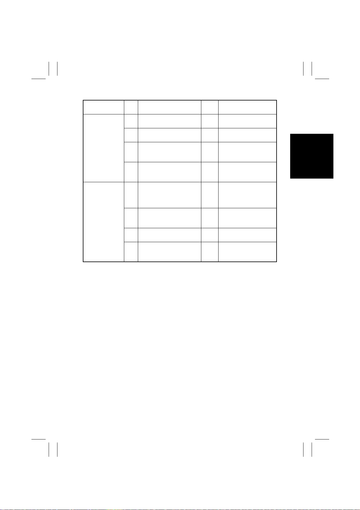
Symptom
•
The document
is fed in askew.
•
The document
wrinkles or
breaks.
Step
No.
1 Is a foreign object present
along the document path?
2 Is the Take-Up Cov er cl osed
in position?
3 Does the document consist
of pages of different sizes?
4 Is any of the rollers
deformed, worn, or dirty with
paper dust?
1 Does the document being
used fall outside the category of reliable feeding?
2 Has the capacity of the Doc-
ument Loading Tray been
exceeded?
3 Is a foreign object present
along the document path?
4 Is any of the rollers
deformed, worn, or dirty with
paper dust?
Check Item Result Action
YES Remove the foreign
object.
NO Close the cover in posi-
tion.
YES Align one edges properly
when loading the document.
YES Clean or change the
defective roller.
YES Instruct the user to use
the document that meets
the specifications for reliable feeding.
YES Instruct the user not to
exceed the capacity.
YES Remove the foreign
object.
YES Clean or change the
defective roller.
T-3
Page 26
3568724
A
B
C
D
91
A
B
C
D
E
F
G
H
I
DWG.NO.
TITLE
MODEL
VOLTAGE
EFFECTIVE
MACHINE NO.
DATE ISSUED
4490-C001-0A
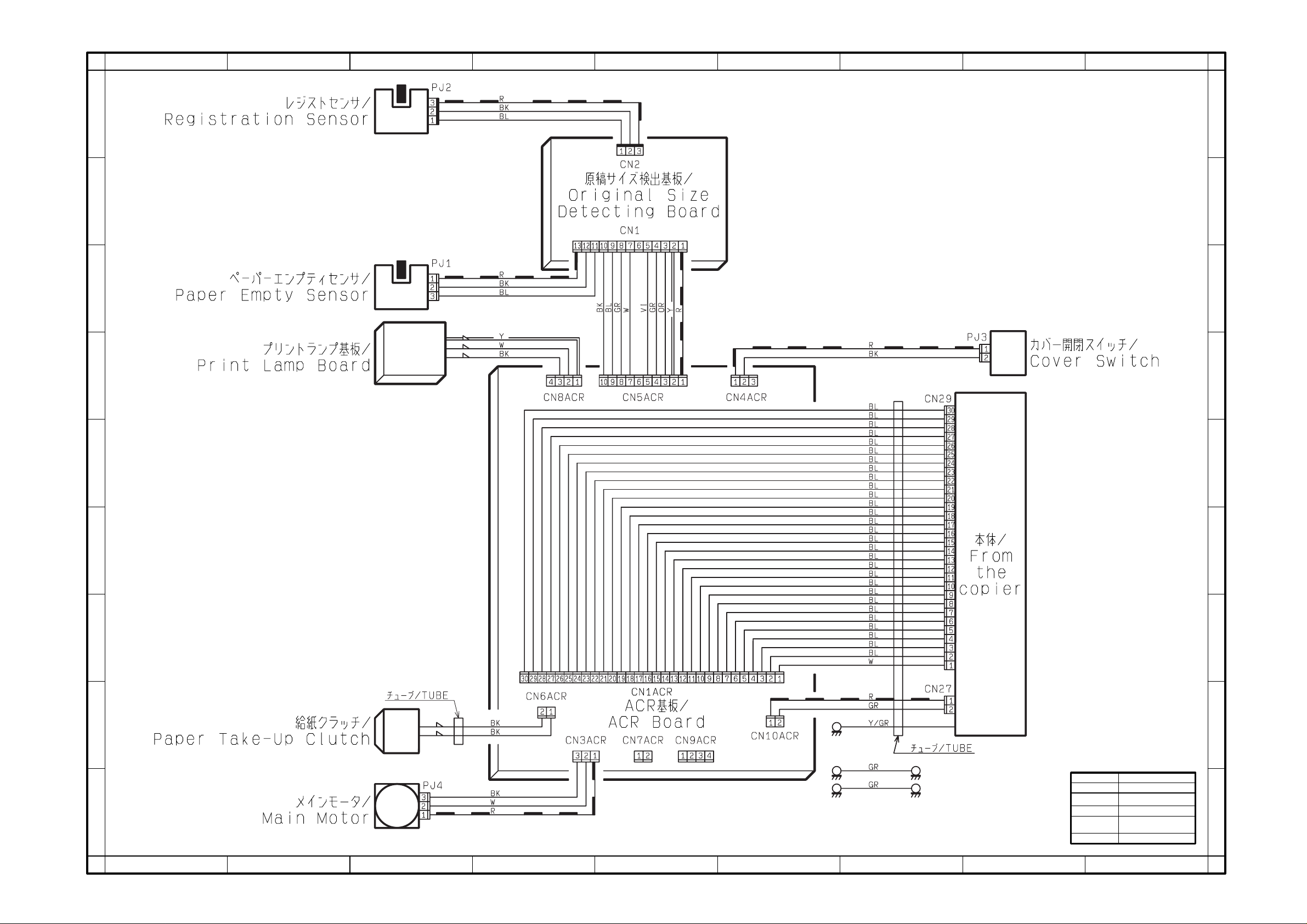
WIRING DIAGRAM
AF-6/AF-7
From the copier
XX010 AND ONWARD
Dec.1998
E
F
G
H
I
12345678
9
 Loading...