

Page 1

FrameMaker Ver.5.5(PC) AD-10 OPTION FOR Di350
98.08.25
AD-10
SERVICE MANUAL
14413
Page 2

FrameMaker Ver.5.5(PC) AD-10 OPTION FOR Di350
98.08.25
CONTENTS
GENERAL, MECHANICAL/ELECTRICAL
1. SPECIFICATIONS ........................................................................................... M-1
2. PARTS IDENTIFICATION ................................ ........................... ....................M-2
3. CROSS-SECTIONAL VIEW ............................................................................M-2
4. DRIVE SYSTEM ..............................................................................................M-3
5. ELECTRICAL COMPONENTS LAYOUT ........................................................M-3
6. MECHANICAL OPERATIONS .........................................................................M-4
6-1. Switchback Mechanism ...........................................................................M-4
(1) Switchback Operation ......................................................................M-4
(2) Paper Exit Roller Drive Coupling Mechanism ..................................M-4
(3) Switchback Motor Control ................................................................M-5
6-2. Transport and Duplex Paper Take-Up Mechanism .................................M-5
(1) Transport and Duplex Paper Take-Up Operation ............................M-5
(2) Duplex Unit Transport Motor Control ...............................................M-5
6-3. 2-Sided Copying Schemes ...................................................................... M-6
(1) Operation of Single-Sheet 2-Sided Copying ....................................M-6
(2) Operation of Double-Sheet 2-Sided Copying ..................................M-8
DIS/REASSEMBLY, ADJUSTMENT
1. DISASSEMBLY ..............................................................................................D-1
1-1. Removal of the Duplex Unit .....................................................................D-1
1-2. Cleaning of Duplex Unit Transport Roller 1 and 2 and
Duplex Unit Transport Roll 1 and 2 ..........................................................D-1
1-3. Cleaning of Exhaust Vent area ....................... ................. ........................D-2
2. ADJUSTMENT .................................................................................................D-2
2-1. Duplex CD Registration Adjustment (Printer) ..........................................D-2
MISFEED DETECTION
1. MISFEED DETECTION .............................. ........................... ..........................T-1
1-1. Misfeed Detecting Sensors Layout ........................ ............................... ...T-1
1-2. Types of Misfeed and Misfeed Detection Timings ...................................T-1
i
Page 3

FrameMaker Ver.5.5(PC) AD-10 OPTION FOR Di350
98.08.25
GENERAL,
MECHANICAL/ELECTRICAL
Page 4

FrameMaker Ver.5.5(PC) AD-10 OPTION FOR Di350
98.08.25
1 SPECIFICATIONS
Type : Switchback and Circulating Duplex Unit
Installation : Mounted on the right side door of copier
Type of Paper : Plain paper (60 to 90 g/m² or 16 to 24 lbs.), recycled
paper (60 to 90 g/m² or 16 to 24 lbs.)
Paper Size : A5L/C to A3L or 5-1/2” × 8-1/2”L/C to 11” × 17”L
Registration : Center
Power Requirements : DC24V ±10%, DC5V ±10% (supplied from copier)
Power Consumption : 21W or less
Dimensions : 55 (W) × 415 (D) × 255 (H) or 2-1/4” (W) × 16-1/4” (D) ×
Weight : 1.8 kg or 4 lbs.
Environmental Requirements : Same as copier
(L: Lengthwise; C: Crosswise)
10” (H)
M-1
Page 5
FrameMaker Ver.5.5(PC) AD-10 OPTION FOR Di350
98.08.25
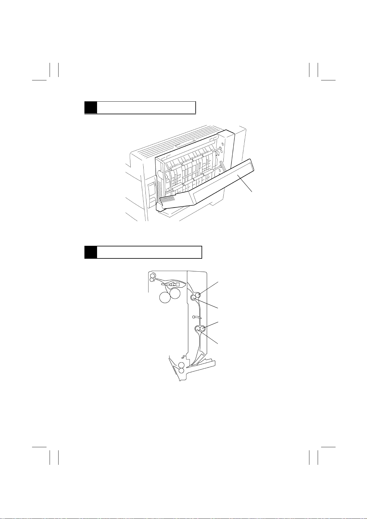
2 PARTS IDENTIFICATION
1. Duplex Unit Door
1
4497M001AA
3 CROSS-SECTIONAL VIEW
1. Duplex Unit Transport Roller 1
2. Duplex Unit Transport Roll 1
1
2
3
4
4497M002AA
3. Duplex Unit Transport Roller 2
4. Duplex Unit Transport Roll 2
M-2
Page 6
FrameMaker Ver.5.5(PC) AD-10 OPTION FOR Di350
98.08.25
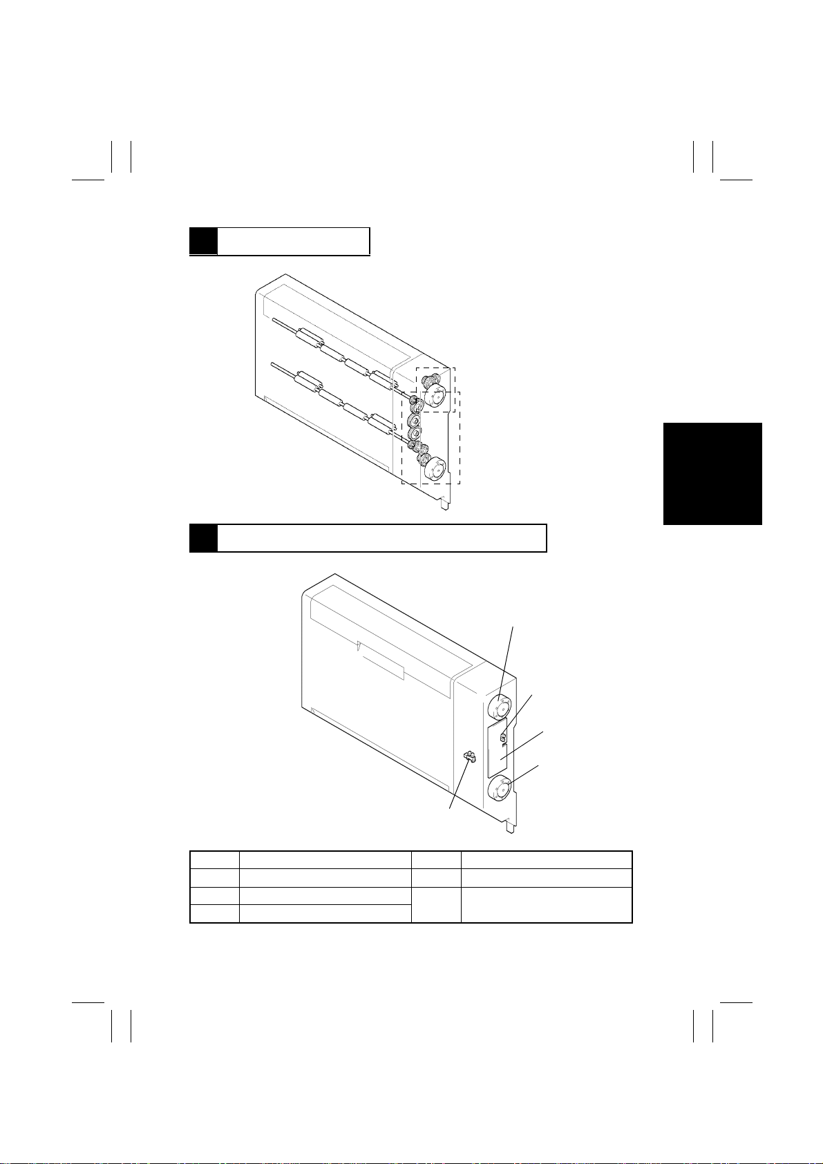
4 DRIVE SYSTEM
Switchback Drive Mechanism
Duplex Unit Transport
Drive Mechanism
4497M014AA
5 ELECTRICAL COMPONENTS LAYOUT
M1
PI1
PWB-A
M2
S2
Symbol Name Symbol Name
PWB-A Duplex Main Board S2 Duplex Unit Door Set Sensor
M1 Switchback Motor PI1 Duplex Unit Transport Sensor (in
M2 Duplex Unit Transpor t Motor
PWB-A)
4497M013AA
M-3
Page 7
FrameMaker Ver.5.5(PC) AD-10 OPTION FOR Di350
98.08.25
6 MECHANICAL OPERATIONS
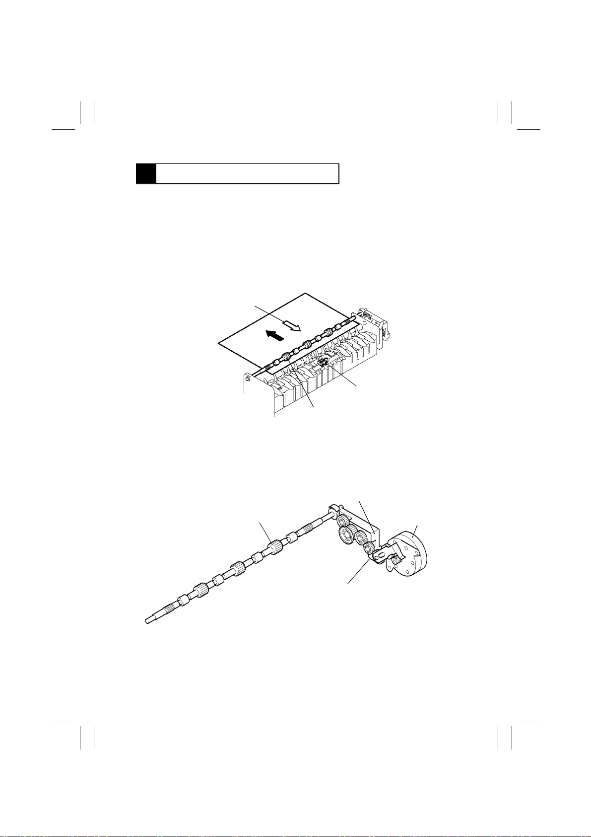
6-1. Switchback Mechanism
(1) Switchback Operation
The Paper Exit Roller rev erses the direction of f eeding the 1-sided copy into the Duple x Unit
(switchback operation). This s witchbac k operation b y the P aper Exit Roller is accomplished
by changing the direction of rotation of the Switchback Motor whose drive is transmitted via
a gear train. When the motor is turned forward, the paper is f ed out of the copier. When the
motor is turned backward, the paper is fed into the Duplex Unit.
Feeding the Paper into Duplex Unit
Paper Exit Sensor PC3
Paper Exit Roller
(2) Paper Exit Roller Drive Coupling Mechanism
When the Duplex Unit is mounted, the tip of the Duplex Unit Lever raises the Idle Lever to
disconnect the drive from the copier (Fusing Roller) and, instead, provides the Paper Exit
Roller with the drive from the Switchback Motor.
Idle Lever
Paper Exit Roller
Duplex Unit Lever
4497M003AA
Switchback
Motor M1
4497M004AA
M-4
Page 8
FrameMaker Ver.5.5(PC) AD-10 OPTION FOR Di350
98.08.25
(3) Switchback Motor Control
The Switchback Motor is a two-phase stepping motor. Its direction of rotation and speed
are controlled by applying pulse signals output from pins 1 to 4 of PJ3A to the motor.
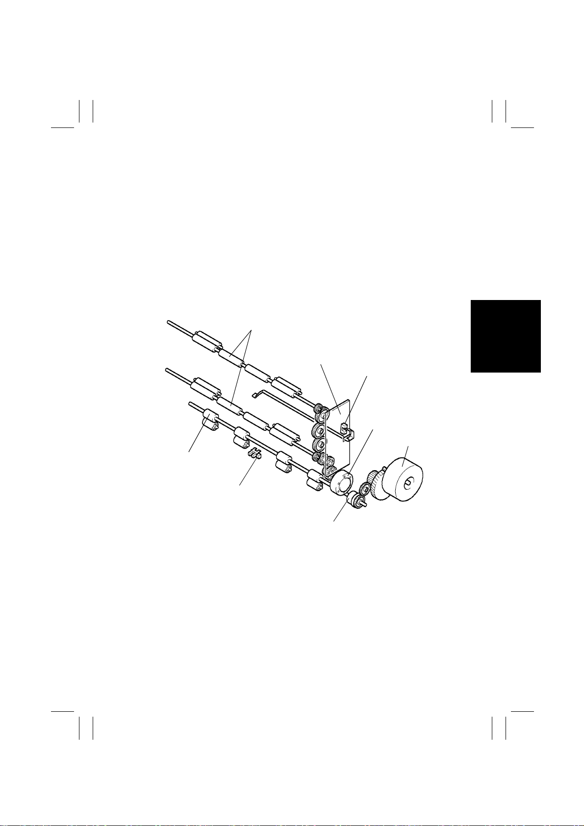
6-2. Transport and Duplex Paper Take-Up Mechanism
(1) Transport and Duplex Paper Take-Up Operation
The paper fed into the Duplex Unit is transported through, and eventually fed out of, the
Duplex Unit before being fed to the paper take-up mechanism of the copier.
The transport and Duplex paper take-up operations are performed by two pairs of Duplex
Unit Transport Rollers/Rolls and the Manual Feed Paper Take-Up Roll of the copier. The
use of the latter contributes to smaller floor space requirements. The drive for these operations comes from the Duplex Unit Transport Motor and Manual Feed Paper Take-Up Clutch.
Duplex Unit Transport
Rollers 1 and 2
Duplex Main Board
PWB-A
Duplex Unit Transport
Sensor PI1
Duplex Unit Transport
Motor M2
Transport Motor M2
Manual Feed P aper
Take-Up Roll
Manual Feed Paper
Take-Up Sensor PC8
4497M005AB
Manual Feed Paper
Take-Up Clutch CL3
(2) Duplex Unit Transport Motor Control
The Duplex Unit Transport Motor is a two-phase stepping motor. Its speed is controlled by
applying pulse signals output from pins 1 to 4 of PJ2A to the motor.
M-5
Page 9
FrameMaker Ver.5.5(PC) AD-10 OPTION FOR Di350
98.08.25
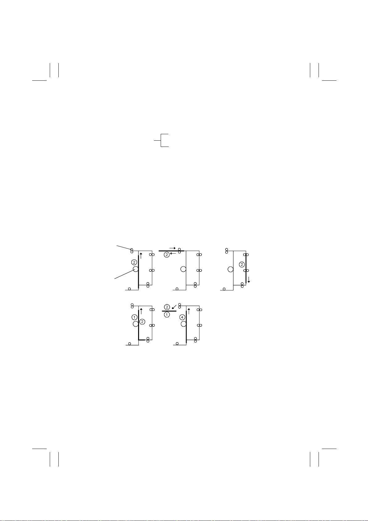
6-3. 2-Sided Copying Schemes
The following two 2-sided copying schemes are available.
Note, however, that the paper size (in the feeding direction) that is applicable to doublesheet 2-sided copying is Letter crosswise (215.9 mm) or smaller.
Single-sheet 2-sided copying
2-Sided Copying Schemes
Double-sheet 2-sided copying
(1) Operation of Single-Sheet 2-Sided Copying
1. A sheet of paper is taken up and fed in and the image of the second page is printed.
2. Just before the 1-sided copy mov es past the Paper Exit Roller, the direction of rotation
of the Paper Exit Roller is reversed and the 1-sided copy is transported towards the
Duplex Unit.
3. The 1-sided copy being transported through the Duplex Unit is fed into the copier without being stopped.
4. The image of the first page is printed on the 1-sided copy f ed out of the Duple x Unit and
the resultant 2-sided copy is fed towards the paper exit section of the copier.
5. As the 2-sided copy is being fed out of the copier, the ne xt sheet of paper is taken up
and fed in for the printing of the image of the fourth page.
(Steps 2 through 5 are then repeated.)
Paper Exit Roller
PC Drum
Step 1 Step 2 Step 3
Step 4 Step 5
4497M016CA
M-6
Page 10
FrameMaker Ver.5.5(PC) AD-10 OPTION FOR Di350
98.08.25
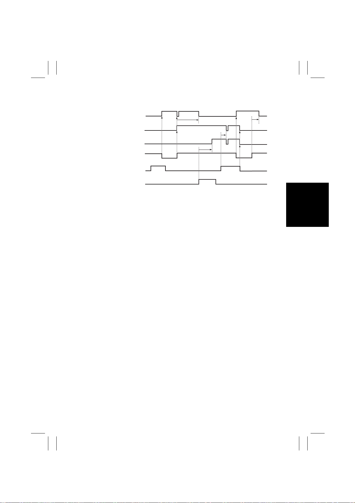
Forward
Switchback
Motor M1
Duplex Unit
Transport Motor M2
Manual Feed Paper
Take-Up Clutch CL3
Paper Exit
Sensor PC3
Synchronizing
Roller Sensor PC2
Duplex Unit
Transport Sensor PI1
✽
When the paper moves a distance of about 20 mm after it has unblocked (H) the Synchronizing Roller Sensor, both Duplex Unit Transport Motor M2 and Manual Feed Paper
Take-Up Clutch CL3 are temporarily deenergized. (The period of time during which M2
and CL3 are kept deenergized varies depending on the Image Synchronizing signal output timing.
ON
OFF
ON
OFF
ON
OFF
H
L
H
L
H
L
Rotation
Backward Rotation
(Paper Length + 30 mm)
Forward
Rotation
4497T02MBC
M-7
Page 11
FrameMaker Ver.5.5(PC) AD-10 OPTION FOR Di350
98.08.25
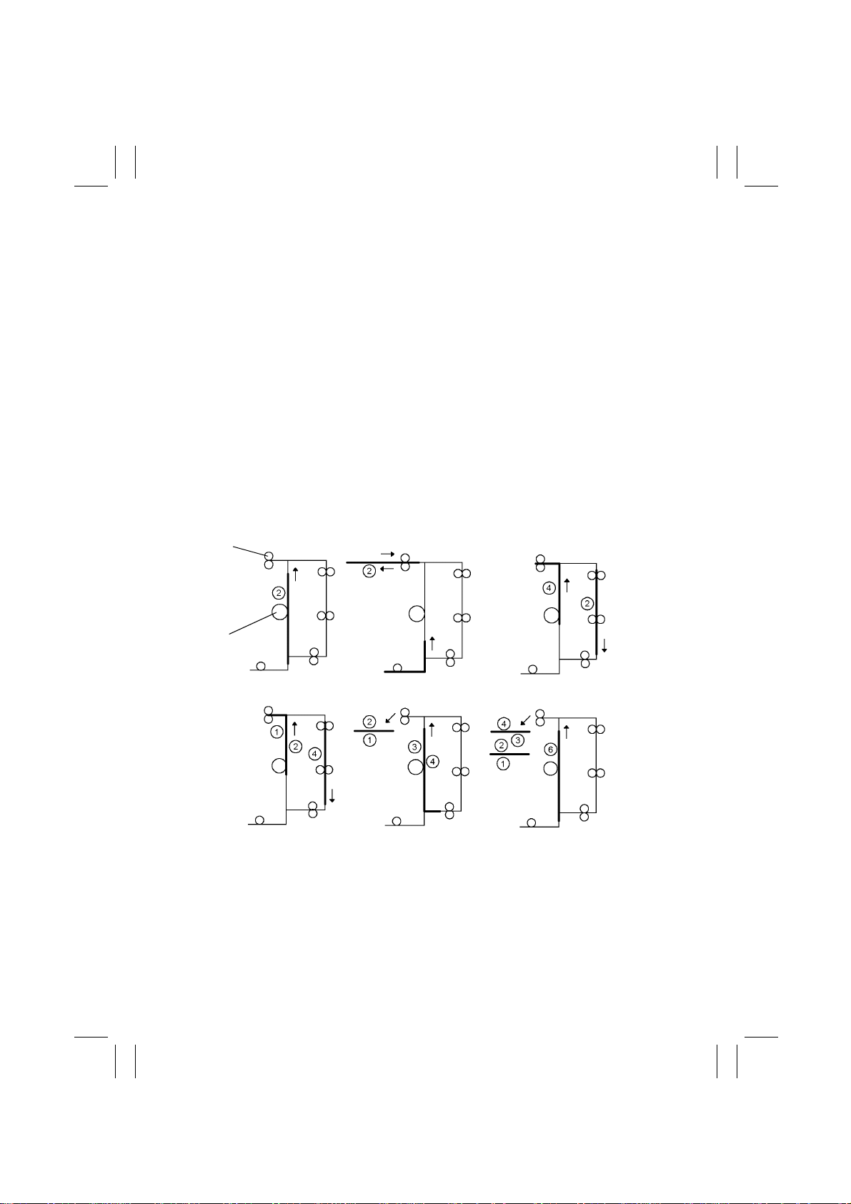
(2) Operation of Double-Sheet 2-Sided Copying
1. The first sheet of paper is taken up and fed in and the image of the second page is
printed.
2. Just before the 1-sided copy mov es past the Paper Exit Roller, the direction of rotation
of the Paper Exit Roller is reversed and the 1-sided copy is transported towards the
Duplex Unit. At the same time, the second sheet of paper is taken up and fed in.
3. At the same time when the image of the fourth page is printed on the second sheet of
paper, the first 1-sided cop y is transported through the Duplex Unit. Because of the
Duplex paper take-up timing involved, the first 1-sided copy is temporarily stopped at a
point 20 mm before the Manual Feed Take-Up Roll; but it is soon fed out of the Duplex
Unit.
4. The image of the first page is printed on the first 1-sided copy fed out of the Duplex Unit.
At the same time, the second 1-sided copy is reversed at the paper exit section of the
copier and transported towards the Duplex Unit. It is then fed out of the Duplex Unit
without being stopped.
5. The image of the third page is printed on the second 1-sided copy.
6. As the second 2-sided copy is fed towards the paper exit section of the copier and as it
is being fed out of the copier, the third sheet of paper is taken up and fed in for the printing of the image of the sixth page.
(Steps 2 through 6 are then repeated.)
Paper Exit Roller
PC Drum
Step 1 Step 2 Step 3
Step 4 Step 5 Step 6
M-8
4497M017CA
Page 12

FrameMaker Ver.5.5(PC) AD-10 OPTION FOR Di350
98.08.25
DIS/REASSEMBLY,
ADJUSTMENT
Page 13
FrameMaker Ver.5.5(PC) AD-10 OPTION FOR Di350
98.08.25
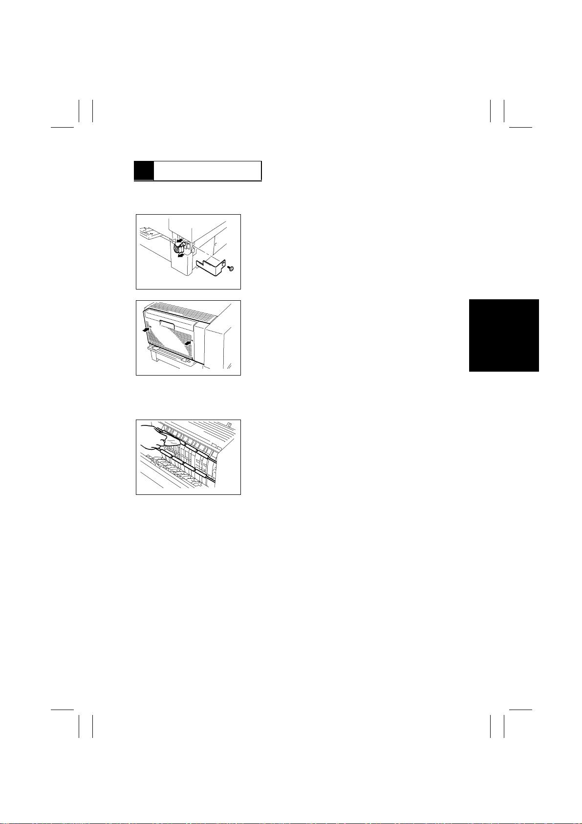
1 DISASSEMBLY
1-1. Removal of the Duplex Unit
1. Remove the wiring cover (one screw).
2. Unplug the connectors (two).
4497M010AA
3. Remove the Duplex Unit (two screws).
4497M011AA
1-2. Cleaning of Duplex Unit Transport Roller 1 and 2 and Duplex
Unit Transport Roll 1 and 2
Wipe the surfaces of Duplex Unit Transport Roller 1 and 2
and Duplex Unit Transpor t Roll 1 and 2 clean with a soft
cloth dampened with alcohol.
4497M012AA
D-1
Page 14
FrameMaker Ver.5.5(PC) AD-10 OPTION FOR Di350
98.08.25
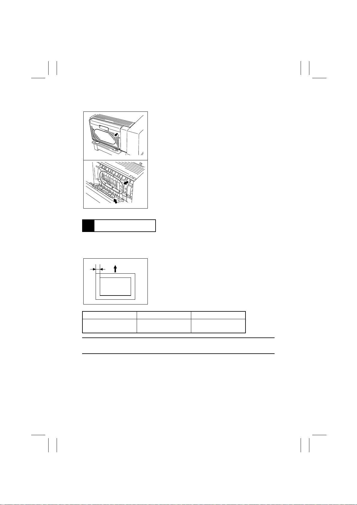
1-3. Cleaning of Exhaust Vent area
1. Wipe the surface of the Exhaust Vent areas clean
with a soft cloth dampened with alcohol.
4497D004AA
4497D005AA
2 ADJUSTMENT
2-1. Duplex CD Registration Adjustment (Printer)
Requirement:
A
4486D046AA
Specifications Adjustment Mode Setting Range
A4C 10.0 ± 3.0 mm
Letter C 10.0 ± 3.0 mm
NOTE:
This adjustment should be made whenever the PH has been replaced with a new one.
For the adjustment procedures, see ADJUSTMENT in the SERVICE MANUAL for the
copier.
First perform the adjustments listed below. The make a
test copy and use it as the original to make a 2-sided
copy. Dimension A on the 2-sided copy should be
adjusted to meet specifications.
1. CD registration for all paper sources and FD registration of the printer.
2. CD and FD registration of the IR.
Registration CD -4 to +4
D-2
Page 15

FrameMaker Ver.5.5(PC) AD-10 OPTION FOR Di350
98.08.25
MISFEED DETECTION
Page 16
FrameMaker Ver.5.5(PC) AD-10 OPTION FOR Di350
98.08.25
1 MISFEED DETECTION
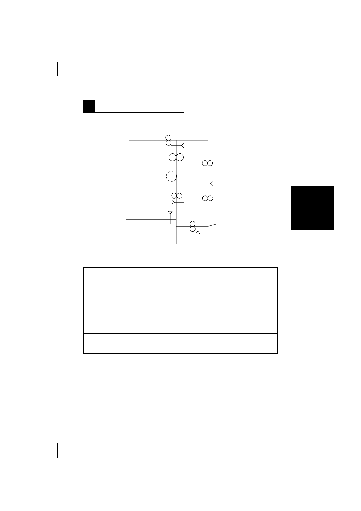
1-1. Misfeed Detecting Sensors Layout
Paper Exit Sensor
PC3
Synchronizing Roller
Sensor PC2
Duplex Unit Transport
Sensor PI1
4497M009AA
1-2. Types of Misfeed and Misfeed Detection Timings
Type Detection Timing
Paper left The output from Duplex Unit Transport Sensor PI1 is
blocked (L) when the copier Power Switch is turned ON or
a misfeed is reset.
Paper take-up failure 1. Synchronizing Roller Sensor PC2 is unblocked (H) at
a shorter than normal time after a Duplex paper takeup sequence has started.
2. Synchronizing Roller Sensor PC2 is not unblocked (H)
within a given period of time after a Duplex paper
take-up sequence has started.
Paper leading edge detection
during transport through
Duplex Unit
Duplex Unit Transport Sensor PI1 is not blocked (H)
within a given period of time after Paper Exit Sensor PC3
has been unblocked (H).
T-1
Page 17
3568724
A
B
C
D
91
A
B
C
D
E
F
G
H
I
DWG.NO.
TITLE
MODEL
VOLTAGE
EFFECTIVE
MACHINE NO.
DATE ISSUED
4497-C001-0A
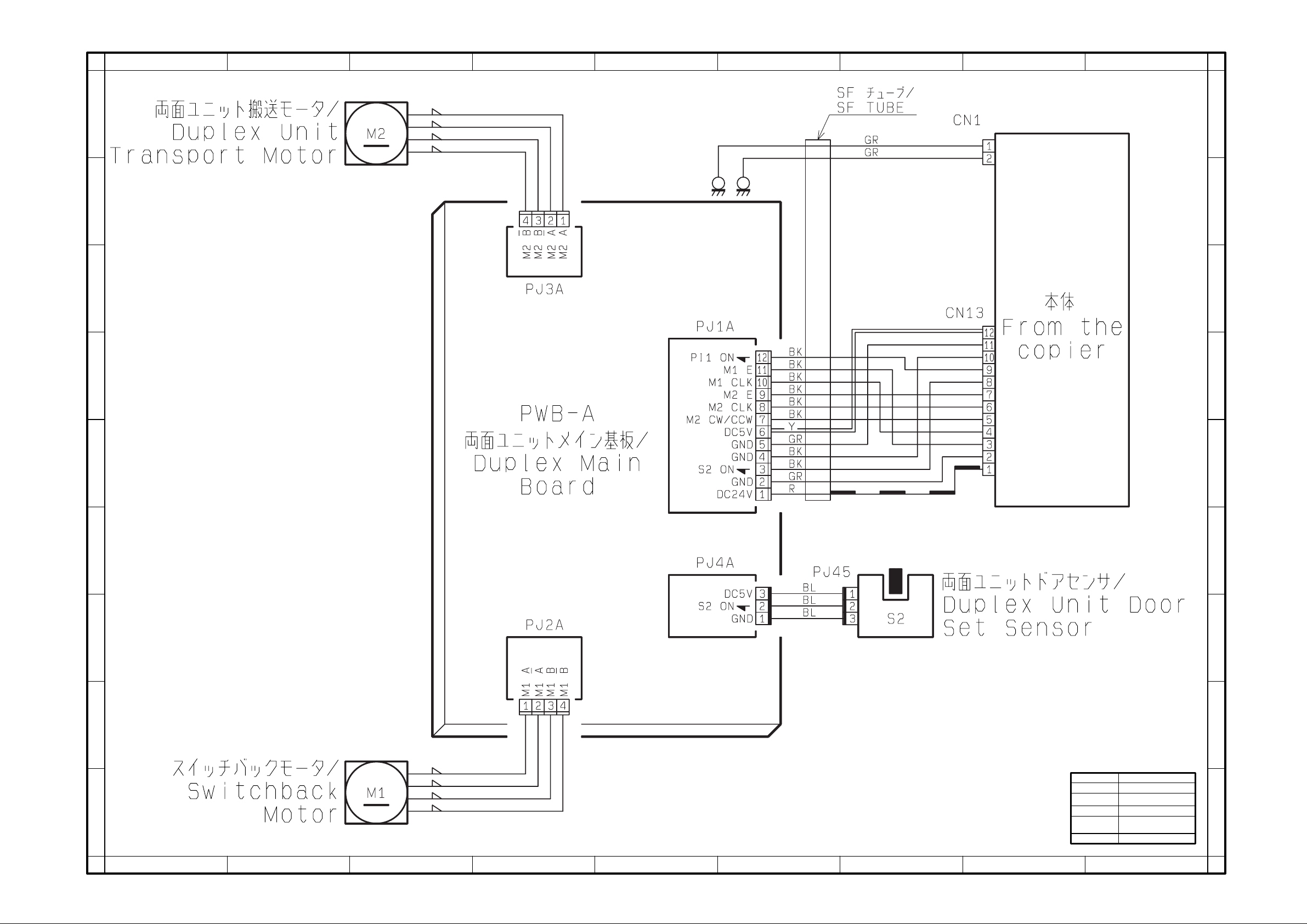
WIRING DIAGRAM
AD-10
From the copier
XX0201 AND ONWARD
Dec.1998
E
F
G
H
I
12345678
9
Page 18
3568724
A
B
C
D
91
A
B
C
D
E
F
G
H
I
DWG.NO.
TITLE
MODEL
VOLTAGE
EFFECTIVE
MACHINE NO.
DATE ISSUED
4497-C201-0A
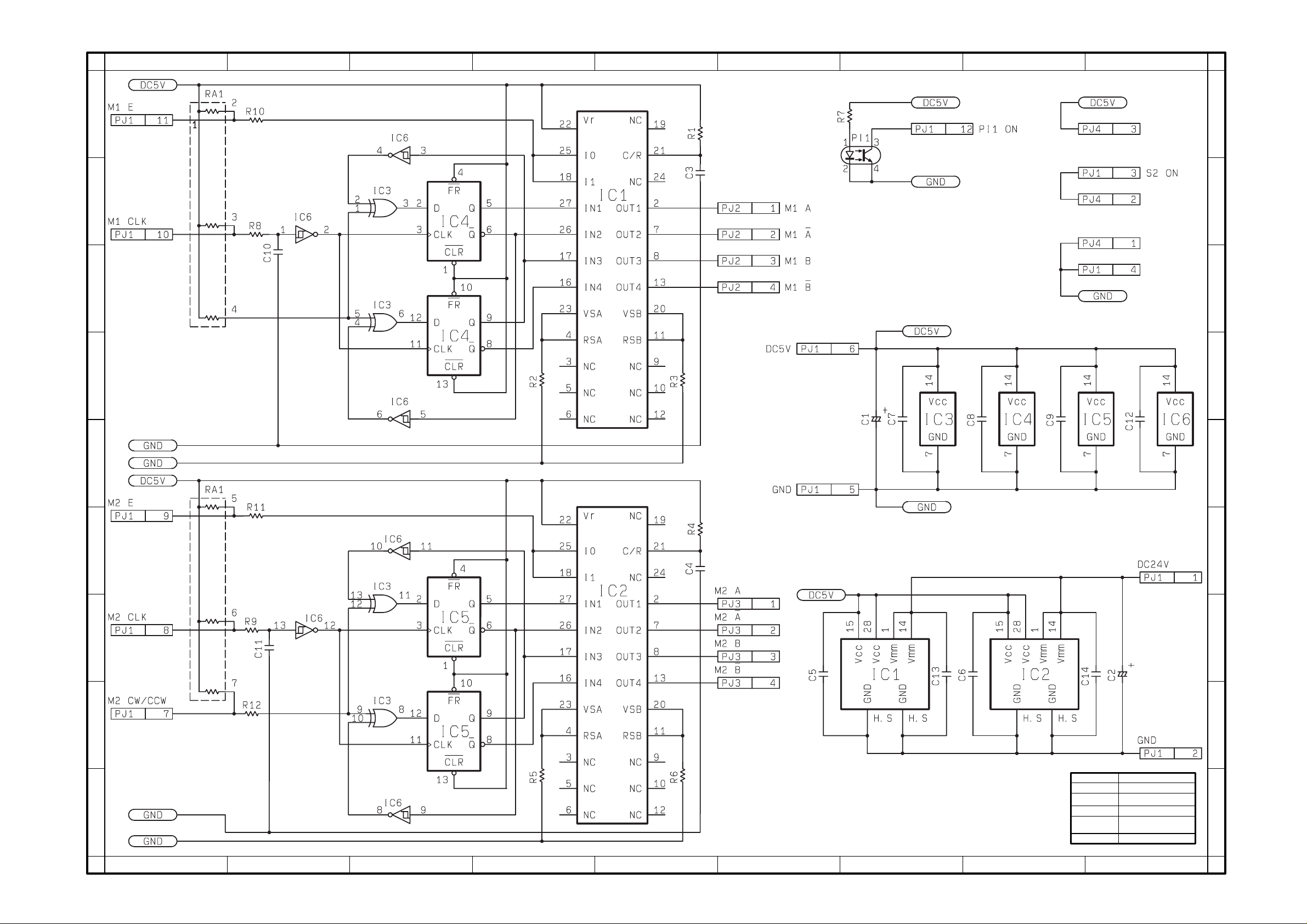
CIRCUIT DIAGRAM PWB-A
AD-10
From the copier
XX0201 AND ONWARD
Sep.1998
E
F
G
H
I
12345678
9
 Loading...