

Page 1
VI
VI
Troubleshooting
Troubleshooting
1. Paper Misfeed Detection
2. Malfunction Detection
3. Image-Related Troubleshooting
4. No Power
Page 2
1.
1.
Paper
Paper
Misfeed
Misfeed
Detection
Detection
I
H
E
G
A
F
B
C
D
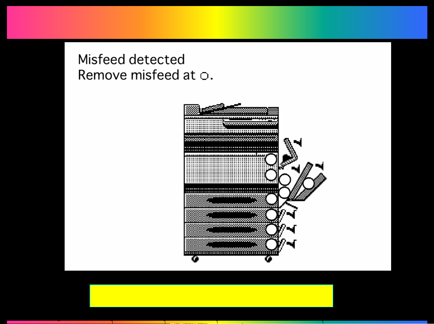
Misfeed Detecting Sensor Layout
Page 3
2.
2.
Malfunction Detection
Malfunction Detection
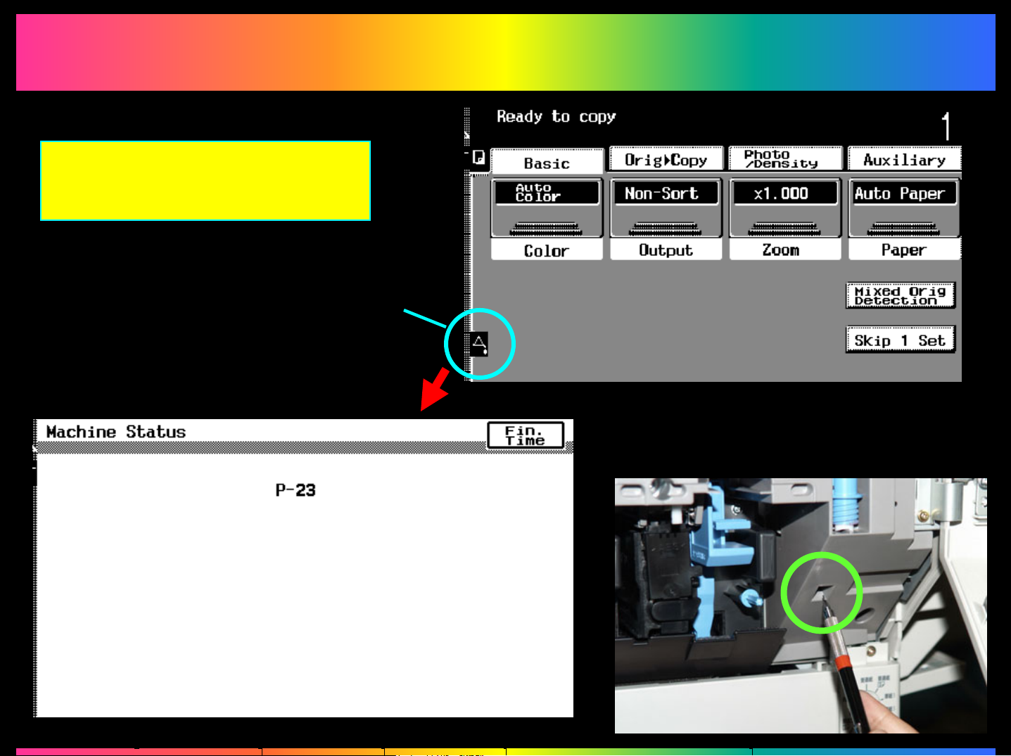
Warning Code /
Malfunction Code List
Maintenance Call Mark
Trouble Reset Switch
Page 4
3.
3.
Image--
Image
Related Troubleshooting
Related Troubleshooting
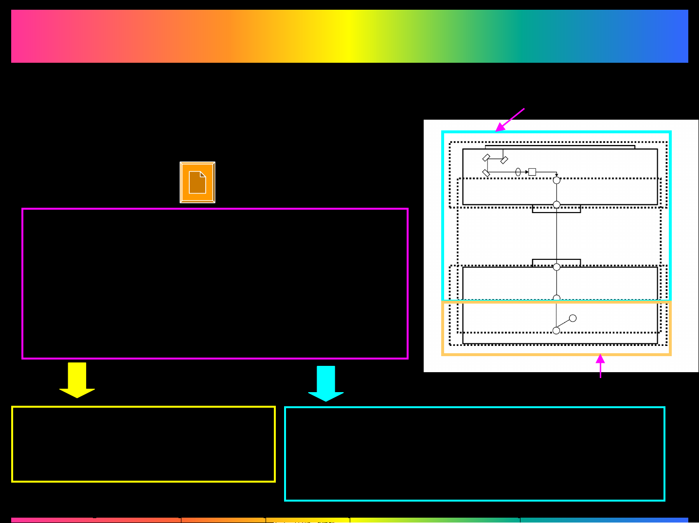
Initial Check Items
1. Make the “Gradation Adjust”, “PRT Max. Density”
or “PRT Highlight” adjustment in the Tech. Rep
Mode.
2. Test Print Output
Select the test pattern suitable for the image
failure problem in Tech. Rep. Mode. Use Test
Print Mode, then judge if the cause of the
problem is due to a malfunction in the Printer
Engine by making a test print.
Is the image failure problem is reproduced on the
test pattern?
Scanner Section or the Image
Control Board
CCD Sensor
Image processing Board (IR)
I/F cable
Image Control Board (Memory)
PIC Board
(Printer)
Test print
Problem is due to a malfunction
in the Printer Engine
To “Printer Engine-Related”
NOYES
Printer Engine Section
Problem is due to a malfunction in the Scanner
Section or the Image Processing Board
To “Scanner Section or Image Control
board-Related”
Page 5
3.1
3.1
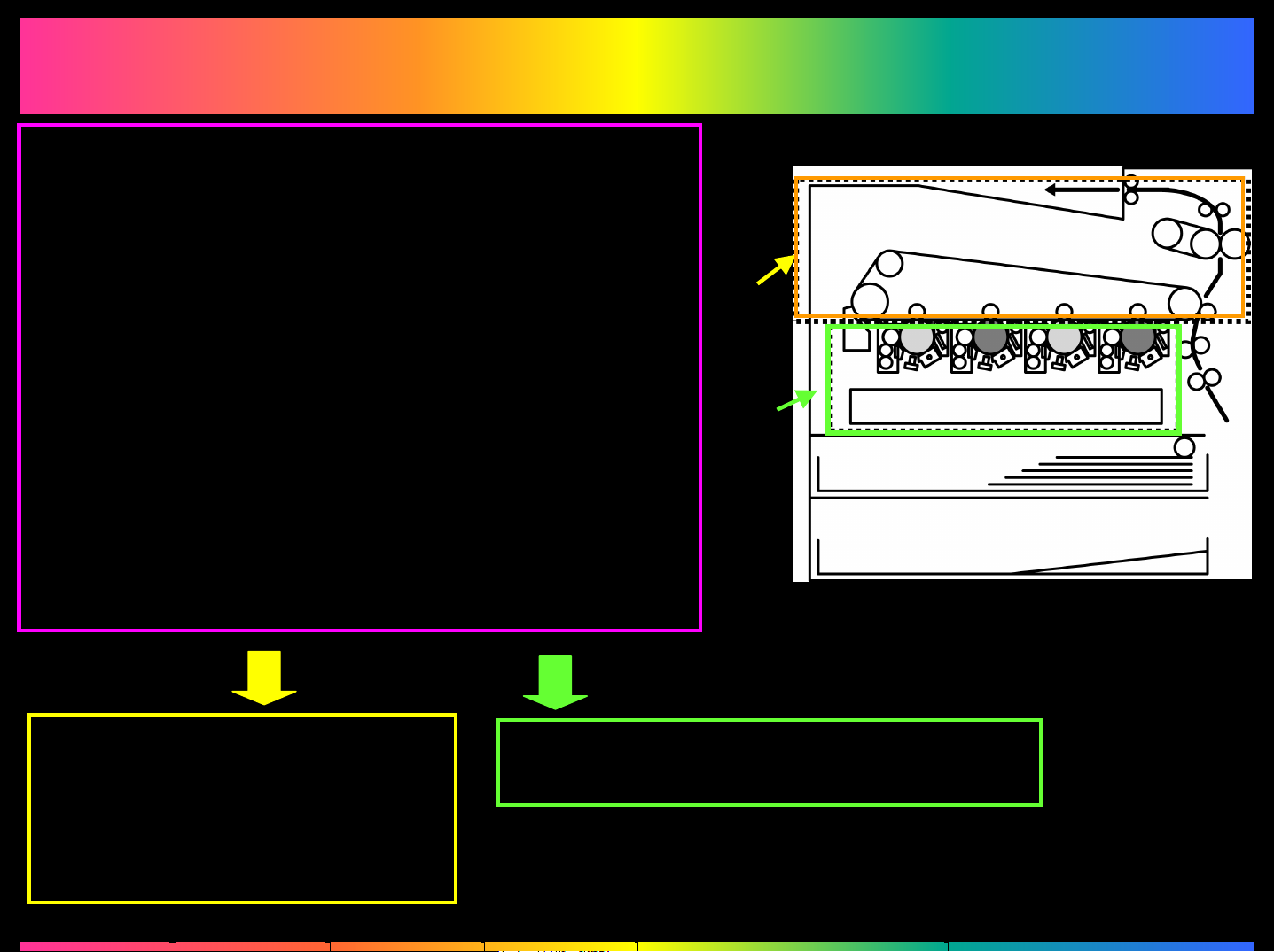
Select the test pattern suitable for the
image failure problem in Tech. Rep.
Mode. Use Test Print Mode, then
judge if the image failure problem is
reproduced in the mono-color or in 4
colors by making a test print when the
Printer Engine--
Printer Engine
Related
Related
4
Colors
cause of the failure is due to
malfunction in the Printer Engine
Section.
Is the same problem is reproduced in
all of 4 colors?
YES
Problem is due to a
malfunction in the Transfer
Belt Unit Section, Transfer
Roller Unit Section or Fusing
Unit Section
Problem is due to a malfunction in
the IU
NO
Mono
Color
Page 6
3.2
3.2
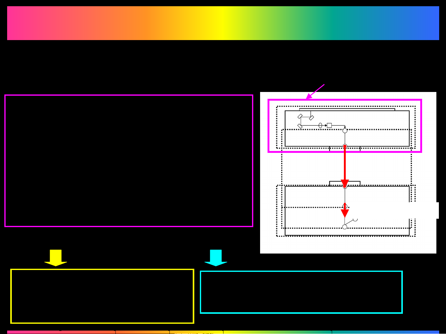
Check to see if the image data has been transferred correctly between the Image
Processing Board and the Image Control Board or between the Image Control
Scanner Section or Image Control Board--
Scanner Section or Image Control Board
Related
Related
Board and the PIC Board.
Check to see if the image data is transferred
correctly between Image Processing Board and
Image Control Board or between Image Control
Board and PIC Board
Checking Procedures:
Enter Tech. Rep. Mode
Depressing Adjust -> Memory/Hard Disk Adjust > Memory Bus Check in this order, select both
[IR->Memory] and [Memory -> PRT ] for checking.
OK NG
IR Section
CCD Sensor
Image Processing Board (IR)
IR -> Memory
Image Control Board (Memory)
PIC Board
(Printer)
I/F Cable
Memory -> Printer
Problem is due to a malfunction of
the Image Processing Board, the
CCD Sensor Section or the Scanner
Section
The cause is due to a failure in the data
transmission at the place with NG
indicated or Image Processing section.
Page 7
4.
4.
No Power
No Power
Troubleshooting
 Loading...