

Page 1

FrameMaker Ver.5.5E(PC) COVER OPTION FOR EP1054/EP1085/EP2030
98.09.11
FrameMaker Ver.5.5E(PC) COVER OPTION FOR EP1054/EP1085/EP2030
98.09.11
PF-112 PF-206
OPTION SERVICE MANUAL PF-112 PF-206 PF-6D/AD-11
PF-6D/AD-11
OPTION
Copyright
1998 MINOLTA Co., Ltd.
Printed in Japan
Use of this manual should
be strictly supervised to
avoid disclosure of
confidential information.
Issued for EP1054/EP1085/EP2030 and Other Models.
SERVICE MANUAL
MINOLTA Co., Ltd.
4479-7990-12 98114400
Page 2
FrameMaker Ver.5.5E(PC) PL Standard Document Ver.01
98.10.02
Safety Precautions for Inspection and Service
When performing inspection and service procedures, observe the following precautions to
prevent accidents and ensure utmost safety.
✽
Depending on the model, some of the precautions given in the following do not apply.
Different markings are used to denote specific meanings as detailed below.
Indicates a potentially hazardous situation which, if not avoided,
WARNING
CAUTION
The following graphic symbols are used to give instructions that need to be observed.
Used to call the service engineer attention to what is graphically represented
inside the marking (including a warning).
Used to prohibit the service engineer from doing what is graphically represented
inside the marking.
could result in death or serious injury.
Indicates a potentially hazardous situation which, if not avoided,
may result in minor or moderate injury. It may also be used to
alert against unsafe practices.
Used to instruct the service engineer to do what is graphically represented inside
the marking.
WARNING
1. Always observe precautions.
•
Parts requiring special attention in this product will include a label containing the
mark shown on the left plus precautionary notes. Be sure to observe the precautions.
•
Be sure to observe the “Safety Information” given in Operator’s Manual.
2. Before starting the procedures, be sure to unplug the power cord.
•
This product contains a high-voltage unit and a circuit with a large current
capacity that may cause an electric shock or burn.
•
The product also contains parts that can jerk suddenly and cause injure.
•
If this product uses a laser, laser beam leakage may cause eye damage or
blindness.
3. Use the specified parts.
•
For replacement parts, always use the genuine parts specified in the manufacturer’s Parts Manual. Installing a wrong or unauthorized part could cause
dielectric breakdown, overload, or undermine safety devices resulting in possible electric shock or fire.
•
Replace a blown electrical fuse or thermal fuse with its corresponding genuine
part specified in the manufacturer’s P arts Manual. Installing a f use of a different
make or rating could lead to a possible fire. If a thermal fuse blows frequently,
the temperature control system is probably of a problem and action must be
taken to eliminate the cause of the problem.
P-1
Page 3

FrameMaker Ver.5.5E(PC) PL Standard Document Ver.01
98.10.02
4. Handle the power cord with care and never use a multiple socket.
•
Do not brake, crush or otherwise damage the power cord. Placing a heavy
object on the power cord, or pulling or bending it may damage it, resulting in a
possible fire or electric shock.
•
Do not use a multiple outlet to which any other appliances or machines is connected.
•
Be sure the power outlet meets or exceeds the specified capacity.
5. Be careful about the high-voltage parts.
•
A part marked with the symbol shown on the left carries a high voltage. Touching it could result in an electric shock or burn. Be sure to unplug the power cord
before servicing this part or the parts near it.
6. Do not keep your hands wet when performing the procedures.
•
Do not unplug or plug in the power cord, or perform any kind of service or
inspection with wet hands. Doing so could result in an electric shock.
7. Do not touch a high-temperature part.
•
A part marked with the symbol shown on the left and other parts such as the
exposure lamp and fusing roller can be very hot while the machine is energized.
Touching them may result in a burn.
•
Wait until these parts have cooled down before replacing them or any surrounding parts.
8. Make a ground connection at all times (This item may not be effected in USA).
•
Be sure to connect a ground wire to the ground terminal even when performing
an inspection or repair. Without proper grounding, electrical leakage could
result in an electric shock or fire.
•
Never connect the ground wire to a gas pipe, water pipe, telephone ground wire,
or a lightning conductor.
9. Do not remodel the product.
•
Modifying this product in a manner not authorized by the manufacturer may
result in a fire or electric shock. If this product uses a laser, laser beam leakage
may cause eye damage or blindness.
10. Restore all parts and harnesses to their original positions.
•
To promote safety and prevent product damage, make sure the harnesses are
returned to their original positions and properly secured in their clamps and saddles in order to avoid hot par ts, high-voltage parts, and sharp edges, or being
crushed.
•
To promote safety, make sure that all tubing and other insulating materials are
returned to their original positions. Make sure that floating components mounted
on the circuit boards are at their correct distance and position off the boards.
P-2
Page 4
FrameMaker Ver.5.5E(PC) PL Standard Document Ver.01
98.10.02
CAUTION
1. Precautions for Service Jobs
•
A toothed washer and spring washer, if used originally, must be reinstalled.
Omitting them may result in contact failure which could cause an electric shock
or fire.
•
When reassembling parts, make sure that the correct screws (size, type) are
used in the correct places. Using the wrong screw could lead to stripped
threads, poorly secured parts, poor insulating or grounding, and result in a malfunction, electric shock or injury.
•
Take great care to avoid personal injury from possible burrs and sharp edges on
the parts, frames and chassis of the product.
•
When moving the product or removing an option, use care not to injure your
back or allow your hands to be caught in mechanisms.
2. Precautions for Servicing with Covers and Parts Removed
•
Wherever feasible, keep all parts and covers mounted when energizing the
product.
•
If energizing the product with a cover removed is absolutely unavoidable, do not
touch any exposed live parts and use care not to allow your clothing to be
caught in the moving parts. Never leave a product in this condition unattended.
•
Never place disassembled parts or a container of liquid on the product parts falling into, or the liquid spilling inside, the mechanism could result in an electric
shock or fire.
•
Never use a flammable spray near the product. This could result in a fire.
•
Make sure the power cord is unplugged before removing or installing circuit
boards or plugging in or unplugging connectors.
•
Always use the interlock switch actuating jig to actuate an interlock switch when
a cover is opened or removed. The use of folded paper or some other object
may damage the interlock switch mechanism, possibly resulting in an electric
shock, injury or blindness.
3. Precautions for Working Environment
•
The product must be placed on a flat, level surface that is stable and secure.
•
Never place this product or its parts on an unsteady or tilting workbench when
servicing.
•
Provide good ventilation at regular intervals if a service job must be done in a
confined space for a long period time.
•
Avoid dusty locations and places exposed to oil mist or steam.
•
Avoid working positions that may block the ventilation port of the product.
4. Precautions for Handling Batteries (Lithium, Nickel-Cadmium, etc.)
•
Replace a rundown battery with the same type as specified in the manufacturer’s parts manual.
•
Before installing a new batter y, make sure of the correct polarity of the installation or the battery could burst.
•
Dispose of used batteries according to the local regulations. Nev er dispose of
them at the user’s premises or attempt to try to discharge one.
P-3
Page 5
FrameMaker Ver.5.5E(PC) PL Standard Document Ver.01
98.10.02
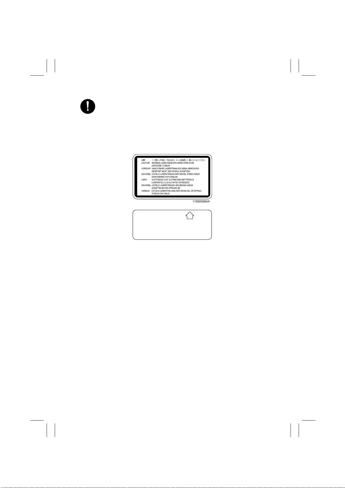
5. Precautions for Laser Beam (Products Employing Laser Only)
•
Removing the cover marked with the follo wing caution label could lead to possible exposure to the laser beam, resulting in eye damage or blindness. Be sure
to unplug the power cord before removing this cover.
•
If removing this cover while the power is ON is una voidable, be sure to wear protective laser goggles that meet specifications.
•
Make sure that no one enters the room when the machine is in this condition.
•
When handling the laser unit, observe the “Precautions for Handling Laser
Equipment.”
.
DANGER
Invisible laser radiation when open.
AVOID DIRECT EXPOSURE
TO BEAM
0947-7127-01
1144D270AA
P-4
Page 6

FrameMaker Ver.5.5E(PC) PL Standard Document Ver.01
98.10.02
Other Precautions
•
To reassemble the product, reverse the order of disassembly unless otherwise specified.
•
While the product is energized, do not unplug or plug connectors into the circuit boards
or harnesses.
•
The magnet roller generates a strong magnetic field. Do not bring it near a watch, floppy
disk, magnetic card, or CRT tube.
•
An air gun and vacuum cleaner generates a strong electrostatic charge that can destroy
the ATDC sensor and other sensors. Before cleaning a component with one of these
devices, be sure to remove all the sensors. Otherwise, use a blower brush and cloth
when cleaning parts.
•
When handling circuit boards with MOS ICs, observe the “INSTRUCTIONS FOR HANDLING THE PWBs WITH MOS ICs” (applicable only to the products using MOS ICs).
•
The PC Drum is a very delicate component. Observe the precautions given in “HANDLING OF THE PC DRUM” because mishandling may result in serious image problems.
•
Note that replacement of a circuit board may call for readjustments or resetting of particular items, or software installation.
•
After completing a service job, perfor m a safety check. Make sure that all parts, wiring
and screws are returned to their original positions.
•
Check the area surrounding the service site for any signs of damage, wear or need of
repair.
•
Do not pull out the toner hopper while the toner bottle is turning. This could result in a
damaged hopper motor or locking mechanism.
•
If the product is to be run with the front door open, make sure that the toner hopper is in
the locked position.
P-5
Page 7

FrameMaker Ver.5.5E(PC) PL Standard Document Ver.01
98.10.02
Used Batteries Precautions
(ALL Areas)
Danger of explosion if battery is incorrectly replaced.
Replace only with the same or equivalent type recommended by the manufacturer.
Dispose of used batteries according to the manufacturer’s instructions.
(Germany only)
Explosinsgefahr bei unsachgemäßen austausch der batterie.
Ersatz nur durch denselben oder einen vom hersteller empfohlenen ähnlichen typ.
Entsorgung gebrauchter batterien nach angaben des herstellers.
(France)
Ily a danger d’explosion s’ily a remplacement incorrec de la batterie.
Remplacer uniquement avec une batterie du meme type ou d’un type équivalent recommande par le constructueur.
Mettre au rebut les batteries usageés conformément aux instructions du fabricant.
(Denmark only)
Lithiumbatteri - Eksplosionsfare ved fejlagtig håndtering Udskiftning må kun ske med batteri af samme fabrikat og type.
Levér det brugte batteri tilbage til leverandøren.
(Norway only)
Eksplosjonsfare ved feilaktig skifte av batteri.
Benytt samme batteritype eller en tilsvarende type anbefalt av apparatfabrikanten.
Brukte batterier kasseres i henhold til fabrikantens instruksjoner.
CAUTION
VORSICHT!
ATTENTION
ADVA RSEL!
ADVARSEL
(Sweden only)
Explosionsfara vid felaktigt batteribyte.
Använd samma batterityp eller en ekvivalent typ som rekommenderas av apparattillverkaren.
Kassera använt batteri enligt fabrikantens instruktion.
(Finland only)
Paristo voi räjähtää, los se on virheellisesti asennettu.
Vaihda paristo ainoastaan laitevalmistajan suosittelemaan tyyppiin. Hävitä Käytetty paristo
valmistajan ohjeiden mukaisesti.
VARNING
VAROlTUS
P-6
Page 8

FrameMaker Ver.5.5E(PC) INDEX OPTION FOR EP1054/EP1085/EP2030
98.09.25
INDEX (OPTION)
PF-112
PF-206
PF-6D/AD-11
Page 9

FrameMaker Ver.5.5(PC) PF-112 OPTION FOR EP1054/E P1085/EP2030
98.06.08
PF-112
SERVICE MANUAL
10794
Page 10

FrameMaker Ver.5.5(PC) PF-112 OPTION FOR EP1054/E P1085/EP2030
98.06.08
CONTENTS
GENERAL, MECHANICAL/ELECTRICAL
1. SPECIFICATIONS ........................................................................................... M-1
2. COMPONENT IDENTIFICATION ................... .................................................M-1
3. CROSS-SECTIONAL VIEW ............................................................................M-2
4. DRIVE SYSTEM ..............................................................................................M-2
5. ELECTRICAL PARTS LAYOUT ......................................................................M-3
6. VERTICAL TRANSPORT SECTION ...............................................................M-4
7. PAPER TAKE-UP/FEEDING SECTION .......................................................... M-5
7-1. Paper Take-Up Mechanism .....................................................................M-5
(1) Paper Take-up Mechanism .............................................................M-5
(2) Paper Separating Mechanism .........................................................M-6
(3) Paper Pressure Releasing Mechanism ...........................................M-7
7-2. Paper Take-Up Control ............................................................................M-8
(1) Paper Take-Up Motor Control .........................................................M-8
(2) Paper Take-Up Retry Control ..........................................................M-8
(3) Paper Take-Up Interval Control (30 cpm Copier Only) ....................M-9
(4) Double Feed Paper Take-Up Control (30 cpm Copier Only) ...........M-9
7-3. Shift Tray and Main Tray .................. .......................................................M-10
7-4. Main Tray Paper Lift-Up Mechanism .......................................................M-10
(1) Main Tray Paper Lift-Up Operation ................................................. .M-10
(2) Paper Top Level Correction .............................................................M-11
7-5. Main Tray Paper Lift-up Control .................... ...........................................M-12
7-6. Shift Gate Drive Mechanism ............................................................. .......M-14
7-7. Shifter Drive Mechanism ..........................................................................M-15
7-8. Shifter Drive Control ................................................................................M-16
7-9. Paper Empty Detection ............................................................................M-18
7-10.Paper Level Detection (30 cpm Copier Only) .......... ................................M-19
7-11.Drawer Lock/Release Mechanism ...........................................................M-20
7-12.Cabinet Paper Dehumidifying Heater (option) .........................................M-21
DIS/REASSEMBLY, ADJUSTMENT
1. DISASSEMBLY ...............................................................................................D-1
1-1. Removal of Exterior Parts ........................................................................D-1
1-2. Removal of 3rd Drawer ............................................................................D-2
1-3. Removal of Wire Drive Pulley ..................................................................D-2
1-4. Removal of Guide Plate and Cover .........................................................D-5
1-5. Removal of Paper Take-Up Roll/Feed Roll Assy .....................................D-5
1-6. Disassembly of Paper Take-Up Roll/Feed Roll Assy ...............................D-6
1-7. Removal of Separator Roll Assy ..............................................................D-7
1-8. Cleaning of Paper Take-Up Roll/Feed Roll and Separator Roll ...............D-8
1-9. Cleaning of Vertical Transport Roller .......................................................D-8
2. ADJUSTMENT ................................................................................................. D-9
2-1. Adjustment of 3rd Drawer Reference Position .......................... ...............D-9
2-2. Adjustment of Shifter Transport Timing Belt ............................................D-10
2-3. Adjustment of Vertical Transport Timing Belt ..........................................D-10
i
Page 11

FrameMaker Ver.5.5(PC) PF-112 OPTION FOR EP1054/E P1085/EP2030
98.06.08
MISFEED DETECTION/MALFUNCTION DETECTION
1. MISFEED DETECTION ......................................................... ..................... .....T-1
1-1. Location of Misfeed Detecting Sensors ...................................................T-1
1-2. Misfeed Detection Types and Detection Timings ....................................T-1
2. MALFUNCTIONS DETECTION ....................................................................... T-2
ii
Page 12

FrameMaker Ver.5.5(PC) PF-112 OPTION FOR EP1054/E P1085/EP2030
98.06.08
GENERAL,
MECHANICAL/
ELECTRICAL
Page 13
FrameMaker Ver.5.5(PC) PF-112 OPTION FOR EP1054/E P1085/EP2030
98.06.08
1 SPECIFICATIONS
Type : Tandem -paper-loading 2,500- sheet Cassette
Type of Copy Paper : Standard and recycled paper
Paper Sizes : A4 C or 11” × 8-1/2”
Paper Weight : 60 to 90 g/m² or 16 to 24 lbs.
Registration : Front edge
Capacity : 2,500 sheets (1,250 × 2) 80 g/m²
2,700 sheets (1,350 × 2) 20 lbs.
Paper Stack Moving : By Shifter
Power Source : DC 24V, DC 5V (supplied from copier)
Power Consumption : 80 W
Dimensions : Width ... 610 mm or 24”
Weight : 36.5 kg
Main Tray moving up/down
Depth ... 595 mm or 23-1/2”
Height ... 472 mm or 18-1/2”
80-1/2 lbs
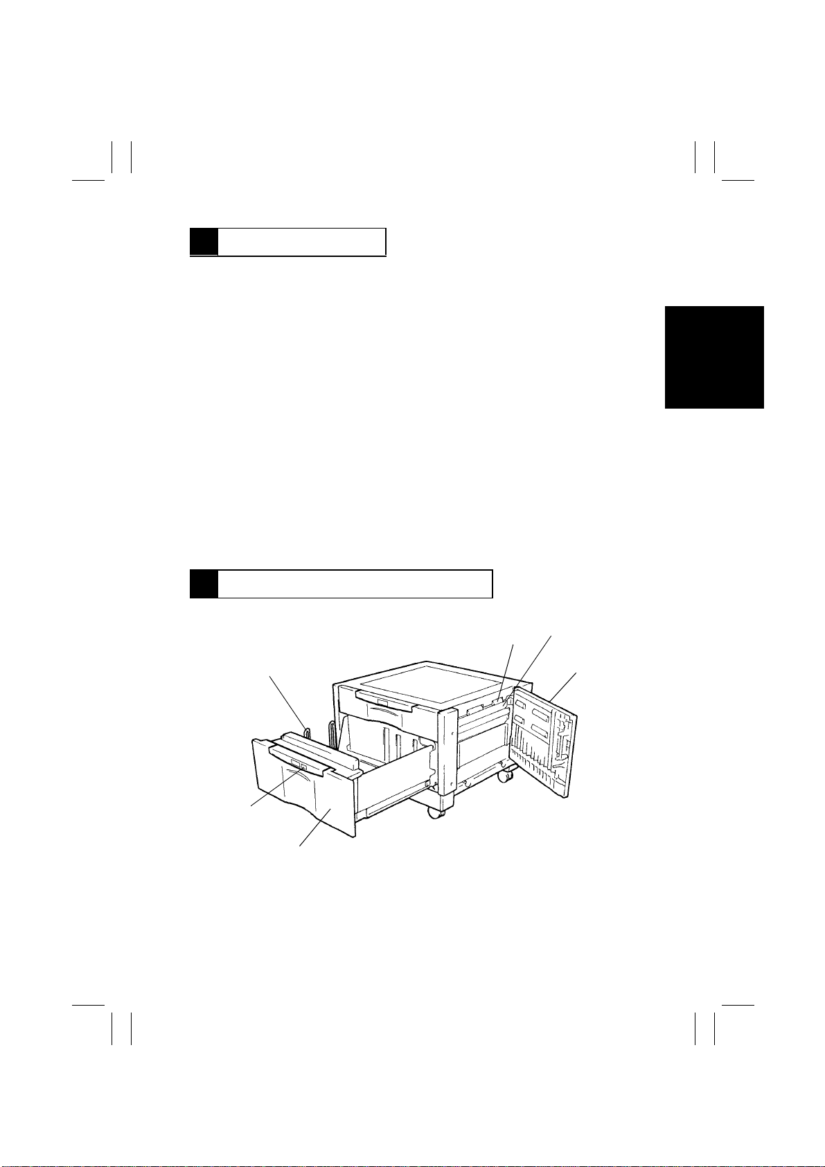
2 COMPONENT IDENTIFICATION
6
5
4
1. Vertical Transport Roller 2
(Drive)
2. Paper Guide Plate
3. Lower Right Door
4. 3rd Drawer
5. Paper Descent Key
6. Shifter
M-1
2
1
3
1174M019AB
Page 14
FrameMaker Ver.5.5(PC) PF-112 OPTION FOR EP1054/E P1085/EP2030
Shifter Drive
Section
98.06.08
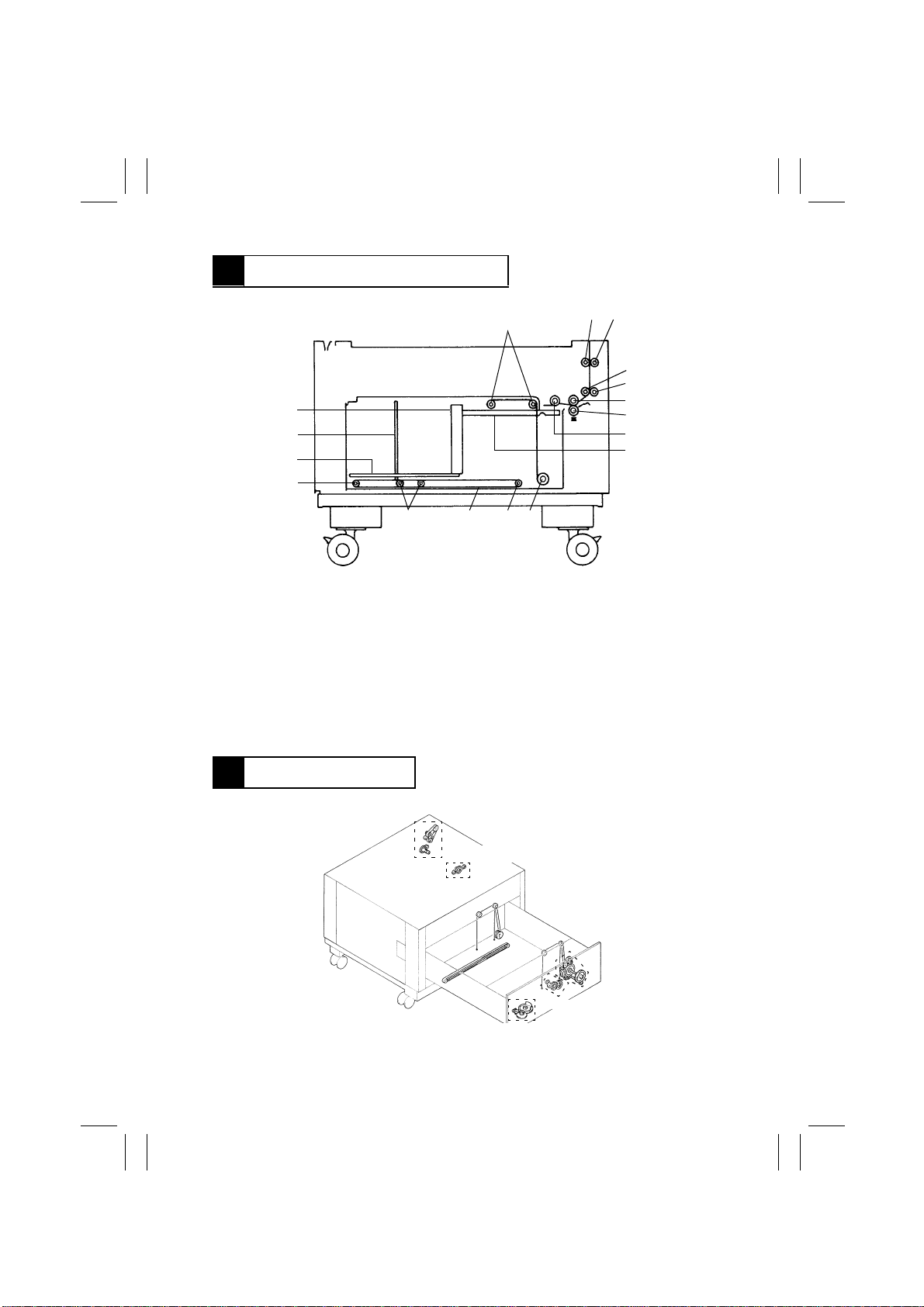
3 CROSS-SECTIONAL VIEW
16
15
14
11
1. Pulley
2. Vertical Transport Roller 2 (Drive)
3. Vertical Transport Roller 2 (Driven)
4. Vertical Transport Roller 1 (Drive)
5. Vertical Transport Roller 1 (Driven)
6. 3rd Drawer Feed Roll
7. 3rd Drawer Separator Roll
8. 3rd Drawer Take-Up Roll
1
10111213
9. Main Tray (3rd Drawer)
10. Wire Take-Up Pulley
11. Pulley
12. Shifter Transport Timing Belt
13. Shifter Transport Roller
14. Shift Tray
15. Shifter
16. Shift G a te
23
4444M014AA
4
5
6
7
8
9
4 DRIVE SYSTEM
Vertical Transport
Drive Section
Paper Take-Up Drive Section
Main Tray Paper
Lift-Up Drive
Section
Shift Gate Drive Section
4479M002AB
M-2
Page 15
FrameMaker Ver.5.5(PC) PF-112 OPTION FOR EP1054/E P1085/EP2030
98.06.08
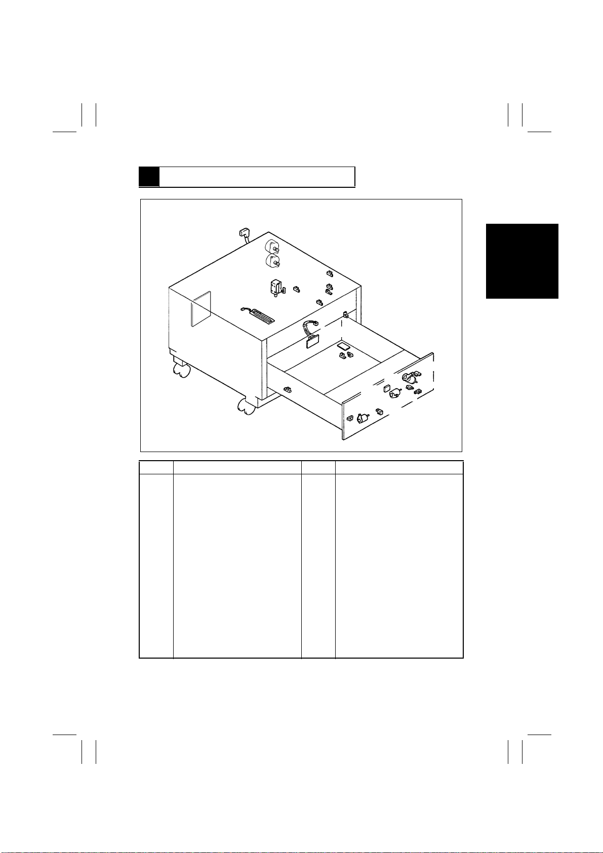
5 ELECTRICAL PARTS LAYOUT
M21
M22
PC7
PC3
PC19
PC20
PC17
PC21
PC22
PC18
PWB-H
PC4
PWB-E
PC2
UN21
PC1
M28
SL41
H22
PWB-A
M27
M26
PC34
PC5
PC35
PC6
4474M001AA
Symbol Name Symbol Name
H22 Cabinet Paper Dehumidifier PC17 Vertical Transport Sensor 3
Heater (Option) PC18 Lower Right Door Sensor
M21 Vertical Transport Motor PC19 3rd Drawer Paper Lift-up Sensor
M22 3rd Drawer Paper Take-up Motor PC20 3rd Drawer Paper Empty Sensor
M26 Main Tray Elevator Motor PC21 3rd Drawer Paper Take-up Sensor
M27 Paper Shift Motor PC22 Vertical Transport Sensor 4
M28 Shift Gate Motor PC34 Shift Gate Position Sensor
PC1 Shif t Tray Paper Empty Sensor PC35 Lower Position Sensor
PC2 Main Tray Lower Position Sensor PWB-A Master Board
PC3 Shifter Home Position Sensor PWB-E Main Tray Paper Empty Board
PC4 Shif ter Return P osition Sensor PWB-H Cabinet Transport Board
PC5 Elevator Motor Pulse Sensor SL41 3rd Drawer Lock Solenoid
PC6 Shif t Motor Pulse Sensor UN21 Paper Descent Key
PC7 3rd Drawer Set Sensor
M-3
Page 16

FrameMaker Ver.5.5(PC) PF-112 OPTION FOR EP1054/E P1085/EP2030
98.06.08
6 VERTICAL TRANSPORT SECTION
1. Vertical Transport Drive Mechanism
•
The Transport Roller is driven by the Vertical Transport Motor.
•
The driving force of the V ertical Transport Motor is transmitted through the belt to the Vertical Transport Roller which feeds the paper from the 3rd Drawer to the copier.
Vertical Transport Roller 2
Vertical Transport Roller 1
Vertical Transport
Motor M21
4425M010AA
2. Vertical Transport Motor Control
•
The Vertical Transport Motor, a stepping motor , is driven by the signals from pins 1, 2, 4
and 17 of IC9A on the cabinet’s Master Board which i s control led by the Master Board of
the copier. These signals are applied to two coils of the Ver tical Transport Motor.
4479T47MCC
M-4
Page 17

FrameMaker Ver.5.5(PC) PF-112 OPTION FOR EP1054/E P1085/EP2030
98.06.08
7 PAPER TAKE-UP/FEEDING SECTION
7-1. Paper Take-Up Mechanism
(1) Paper Take-up Mechanism
•
Paper is taken up from the 3rd Drawer and fed to the Vertical Transport Roller.
•
The take-up mechanism is driven by 3rd Drawer Paper Take-Up Motor.
•
The paper take-up mechanism consists of a Separator Roll with torque limiter, Take-Up
Roll and Feed Roll.
•
The Separator Roll is controlled by the torque limiter so that it wil l not transport more than
one sheet of paper at a time.
•
The wider Take-Up Roll assures straight paper transport.
Take-Up Roll
3rd Drawer Paper
Take-Up Motor M22
Feed Roll
Torque Limiter
Separator Roll
M-5
4425M110AA
Page 18

FrameMaker Ver.5.5(PC) PF-112 OPTION FOR EP1054/E P1085/EP2030
98.06.08
(2) Paper Separating Mechanis m
•
The paper separating mechanism ensures that only the top sheet of paper is fed in by
separating the second sheet of paper from the top one.
•
This is accomplished by the difference in friction coefficient between the Feed and Separator Rolls.
Normal Feeding
•
When only one sheet of paper is fed, the
friction coefficient on the top side of the
paper is equal to that on the underside.
Feed Roll
Paper
Separator Roll
4425M107AA
Driven or stops
Driven by the Feed Roll, the paper drives
the Separator Roll. This causes the paper
to be sent to the Vertical Transpor t Section.
•
The friction coefficient varies for different
ambient conditions and types of paper
being used, which often causes the Separator Roll to be stationary.
Double Feeding
Feed Roll
1st Sheet of Paper
2nd Sheet of Paper
Separator Roll
Stops
4425M108AA
•
Since the coefficient of friction between
the top side of the first sheet of paper and
the Feed Roll is greater than that between
the first and second sheets of paper, the
first sheet of paper is fed into the copier
by the Feed Roll.
Since the friction coefficient between the
second sheet of paper and the Separator
Roll is greater than that between the first
and second sheet of paper, the Separ ator
Roll is not driven and holds the second
sheet of paper.
M-6
Page 19

FrameMaker Ver.5.5(PC) PF-112 OPTION FOR EP1054/E P1085/EP2030
98.06.08
(3) Paper Pressure Releasing Mechanism
•
If the Drawer is pulled out while the paper is between the Feed Roll and the Separator
Roll, the paper is left in the unit. Removal of the paper is difficult.
•
The Paper Pressure Releasing Mechanism makes it easier to remove a sheet of paper
that remains between the F eed Roll and Paper Separator Roll by just pressing the Paper
Descent key. When the Paper Descent key is pressed, the main tray is lowered and the
3rd Drawer is pushed forw ard by approx. 70 mm. At the same time, the pressure release
rail pushes down the Separator Roll, disengaging the Feed Roll from the Separator Roll.
Feed Roll
<Drawer closed>
Pressure Spring
Separator Roll
Assy
<Drawer open>
Approx. 2mm
4444M016AA
M-7
Page 20

FrameMaker Ver.5.5(PC) PF-112 OPTION FOR EP1054/E P1085/EP2030
98.06.08
7-2. Paper Take-Up Control
(1) Paper Take-Up Motor Control
•
The 3rd Drawer Paper Take-up Motor, a stepping motor , is driven by the signals from pins
1, 2, 4 and 17 of IC8A on the cabinet’s Master Board which is controlled by the Master
Board of the copier. These signals are applied to two coils of the 3rd Drawer Paper Takeup Motor.
4479T48MCB
(2) Paper Take-Up Retry Control
•
If the Paper Take-Up Sensor is not activated (does not go low) because it is not blocked
by the paper within a predetermined time after start of paper take-up, the Drawer Paper
Take-Up Motor is started again.
•
A paper misfeed results if a sheet of paper does not reach the Paper Take-Up Sensor
even after three paper take-up sequences.
M-8
4479T49MCC
Page 21

FrameMaker Ver.5.5(PC) PF-112 OPTION FOR EP1054/E P1085/EP2030
98.06.08
(3) Paper Take-Up Interval Control (30 cpm Copier Only)
•
The Paper Feed Roll and Separ ator Roll may sometimes fail to separate the subsequent
sheet of paper properly and the leading edge of that paper may be beyond the Feed and
Separator Rolls inside the copier. If the next paper take-up sequence is started in this
condition, the distance between the preceding and the current sheet of paper will
become shorter than normal, resulting in a misfeed.
•
To maintain a given paper take-up interval, therefore, this copier provides the following
control. If it takes the paper more than a specified time to block (L) Paper Take-Up Sensor after Paper Take-Up Motor has been energized, Paper Take-Up Motor is temporarily
deenergized and, an appropriate period of time thereafter, it is energized again (paper
take-up interval control).
(4) Double Feed Paper Take-Up Control (30 cpm Copier Only)
•
Even if the Paper Take-Up Roll takes up two sheets of paper at one time, the double f eed
paper take-up control uses the second sheet of paper for the next copy cycle without
causing a paper misfeed. It eliminates a paper misfeed that would otherwise result when
two sheets of paper are taken up at once.
•
If the second sheet of paper is stationary blocking Paper Take-Up Sensor when the trailing edge of the first sheet of paper moves past Vertical Transport Sensor, the copier
determines that it is a double feed condition and provides double feed control.
•
If, howe ver, the second sheet of paper has reached the Vertical Transport Roller, the double feed control is not provided since the paper is fed further into the copier by the Vertical Transport Roller. This could result in a paper misfeed or the second sheet of paper
being fed through the copier with the first one.
Detecting position of Vertical
Transport Sensor 4 PC22
Vertical Transport Roller 1
Detecting position of 3rd Drawer
Paper Take-Up Sensor PC21
M-9
Paper Path
(Leading edge of the paper fed
together with the top one)
Multiple paper feed
control function
ON
OFF
4444M041AA
Page 22

FrameMaker Ver.5.5(PC) PF-112 OPTION FOR EP1054/E P1085/EP2030
98.06.08
7-3. Shift Tray and Main Tray
•
The Shift Tray and Main Tray are designed to hold Letter size paper (Inch Areas) or A4
size paper (Metric Areas) loaded to be fed crosswise only.
Shifter
Shift Tray
Main Tray
4479M003AA
7-4. Main Tray Paper Lift-Up Mechanism
(1) Main Tray Paper Lift-Up Operation
•
The Main Tray of the 3rd Drawer is raised and lowered by the Main Tray Elevator Motor
through a gear train, pulleys and 4 wires (at front and rear, two wires each).
1. Main Tray Top Level Position Detection
•
The Main Tray is at its top position when 3rd Drawer Paper Lift-Up Sensor is blocked (L).
2. Main Tray Lower Position Detection
•
The Main Tray is at its lower limit position when the Lower Position Sensor at the drive
mechanism is blocked (L). Main Tray Lower Position Sensor fitted under the Main T r ay
also detects the lower limit position of the Main Tray. It detects a faulty detection of the
Main Tray lower limit when Lower P osit ion Sensor is not blocked.
Main Tray
Shift Tray
Pulley
Main Tray Elevator Motor
M26
3rd Drawer Paper
Lift-Up Sensor
PC19
Wire
Lower Position Sensor PC35
M-10
Pulley
Wire
Main Tray Lower
Position Sensor
PC2
4479M004AA
Page 23

FrameMaker Ver.5.5(PC) PF-112 OPTION FOR EP1054/E P1085/EP2030
98.06.08
(2) Paper Top Level Correction
•
As the number of sheets on the Tray decreases, the pressure exerted by the Paper TakeUp Roll decreases. This may cause paper misfeed. To avoid this problem, the Main Tray
is raised to maintain a constant pressure.
During Copying
•
3rd Drawer Paper
Lift-Up Sensor PC19
As sheets of paper are used, the Paper
Take-Up Roll goes down accordingly,
clearing 3rd Drawer Paper Lift-Up Sensor
(output goes high).
4425M113AA
•
Main Tray Elevator Motor starts running,
raising the Tray until 3rd Drawer Paper
Lift-up Sensor is blocked (output goes
low).
4425M114AA
M-11
Page 24

FrameMaker Ver.5.5(PC) PF-112 OPTION FOR EP1054/E P1085/EP2030
98.06.08
7-5. Main Tray Paper Lift-up Control
1. Main Tray Elevator Motor Control
•
Main Tray Elev ator Motor, a DC motor, is driven by the signals from pins 8 and 4 of IC4A
of the cabinet’s Master Board. IC4A turns on and off and changes the motor running
direction according to the control signals from the Master Board of the copier.
M26 Main Tray
Energized (backward) Up L H
Energized (forward) Down H L
Deenergized Stop L L
Ascent
Descent
IC4A
Pin 8 Pin 4
4479T59MCB
4479T50MCB
M-12
Page 25

FrameMaker Ver.5.5(PC) PF-112 OPTION FOR EP1054/E P1085/EP2030
98.06.08
2. Main Tray Elevator Motor Energization Timing (Main Tray Up/Down Timing)
The Main Tray is Raised When:
A. Any of the following operations is performed with the 3rd Drawer slid into position (3rd
Drawer Set Sensor blocked) and paper loaded on the Main Tray (reflector-type photosensor on Main Tray Paper Empty Board blocked).
No. Operation No. Operation
Paper Descent Key is Pressed.
1
The Power Switch is turned ON.
2
The copier Front Door is swung
3
open any then closed.
An original is loaded into the
4
Duplexing/Aut omati c Document
Feeder .
The Duplexing/Automatic Docu-
5
ment Feeder is raised and then
lowered.
Paper is loaded onto the Manual
6
Bypass Table.
The Sorter is swung up against the
7
copier.
The Duplex Unit is slid into the
8
Cabinet.
Any Key on the copier control
9
panel is pressed.
NOTE:
Condition A for raising the Main Tray applies only to the USA and Canada area model. The
Main Tray for the European area model raises automatically when the drawer is closed.
B. The paper stack on the Shift Tray is shifted to the Main Tray (the reflector-type photo-
sensor on Main Tray Paper Empty Board is blocked (sensor output goes low)).
C. 3rd Drawer Paper Lift-Up Sensor is unblocked (output is high) during paper take-up
sequence (top level correction).
The Main Tray is Lowered When:
A. 3rd Drawer P aper Empty Sensor outputs a high signal indicating that no paper is on the
Main Tray.
B. Paper Descent Key is pressed.
C. The Main Tray is between the upper and lower limit positions when the Power Switch is
turned on.
3. Main Tray Elevator Motor Deenergization Timing (Main Tray Stop Timing)
While the Main Tray is going up:
A. 3rd Drawer Paper Lift-Up Sensor is blocked (sensor output goes low).
B. 3rd Drawer Paper Lift-Up Sensor is blocked (sensor output goes low) during top level
correction.
While the Main Tray is going down:
A. Lower Position Sensor is blocked (sensor output goes low).
M-13
Page 26

FrameMaker Ver.5.5(PC) PF-112 OPTION FOR EP1054/E P1085/EP2030
98.06.08
7-6. Shift Gate Drive Mechanism
1. Shift Gate Drive Operation
•
The Shift Gate serves as a guide against which the paper stacks on the Main and Shift
Tray are aligned.
•
When Shift Gate Motor is energized, it turns the cam, moving the Shift Gate to the front
or rear to allow the paper stack on the Shift Tray to be moved, or blocks it from moving,
onto the Main Tray.
Shift Gate
Shift Gate Motor M28
4479M005AA
Shift Gate Position Sensor PC34
Cam
2. Shift Gate Motor Control
•
Shift Gate Motor is a DC motor and energized or deenergized by the output from pin 8 of
IC5A on the Master Board.
•
As Shift Gate Position Sensor is blocked (L) or unblocked (H), Shift Gate Motor is energized or deenergized to advance or retract the Shift Gate.
M28 Deenergized Energized PC34
→
Pin 8 of IC5A L H
Shift Gate
Advanced Blocked (L)
Retracted Unblocked (H)
Unblocked (H)
→
Blocked (L)
M-14
Page 27

FrameMaker Ver.5.5(PC) PF-112 OPTION FOR EP1054/E P1085/EP2030
98.06.08
7-7. Shifter Drive Mechanism
•
When the Main Tray becomes empty, the Shifter transfers the paper stack from the Shift
Tray to the Main Tray.
•
The Shift Gate serves as a guide against which the paper stacks on the Main and Shift
Tray are aligned.
Shifter
Shift Gate
Main Tray
4480M010AA
•
Paper Shift Motor drives the Shifter through a gear train and belt.
•
The Shifter is at its home position when Shifter Home Position Sensor is blocked (output
goes low).
•
After paper transfer, Paper Shift Motor starts returning the Shifter when the Light Blocking Plate (on the base of the Shifter in the rear) with a cutout in it blocks the Shifter
Return Position Sensor (blocks once for Letter and twice for A4).
Shifter Home Position Sensor PC3
Blocking Plate
Shifter
Paper Shift Motor M27
Shifter Return
Position Sensor
PC4
4425M104AA
M-15
Page 28

FrameMaker Ver.5.5(PC) PF-112 OPTION FOR EP1054/E P1085/EP2030
98.06.08
7-8. Shifter Drive Control
1. Paper Shift Motor Control
•
The Paper Shift Motor controls the Shifter according to the signals from pins 8 and 4 of
IC3A of the cabinet’s Master Board. IC3A is controlled by the motor control signal from
the Master Board of the copier.
M27 Shift Tray
Energized (backward) Transfer L H
Energized (forward) Return H L
Deenergized Stop L L
2. Paper Shift Motor is Energized When:
•
Shifter is to be moved:
The Main Tray has no paper and the Shift Tray has a paper stack: The reflector-type photosensor mounted on Main Tray Paper Empty Board is unblocked (stays high), Shift Tray
Paper Empty Sensor is blocked (sta ys low), and Main Tray Lower Position Sensor is
blocked (stays low).
•
Shifter is to be returned:
The Shifter is not at its home position when power is turned on.
3. Paper Shift Motor is Deenergized When:
•
Shifter is to be stopped:
A. During paper transfer sequence: Shifter Return Position Sensor has been blocked N
times. (Letter C: N=1; A4 C: N=2)
B. During return motion: Shifter Home Position Sensor is blocked (goes low).
Pin 8 Pin 4
IC3A
M-16
Page 29

FrameMaker Ver.5.5(PC) PF-112 OPTION FOR EP1054/E P1085/EP2030
98.06.08
3rd Drawer Paper
Empty Sensor PC20
Main T ra y Paper
Empty Board PWB-E
Main T ra y Elevator
Motor M26 (Up)
M26 (Down)
3rd Drawer Paper
Lift-Up Sensor PC19
Lower Position
Sensor PC35
Paper Shift Motor
M27 (Shift)
M27 (Return)
Shifter Home
Position Sensor PC3
ON
OFF
ON
OFF
H
L
H
L
ON
OFF
ON
OFF
H
L
H
L
H
L
Lowering start
Shifter start
Lift-Up start
Shifter Return start
Shifter Return
Position Sensor PC4
Shift Gate Motor
M28
Shift Gate Position
Sensor PC34
H
L
ON
OFF
H
L
4479T58MCB
M-17
Page 30

FrameMaker Ver.5.5(PC) PF-112 OPTION FOR EP1054/E P1085/EP2030
98.06.08
7-9. Paper Empty Detection
•
The reflector-type photosensor on Main Tray Paper Empty Board and 3rd Drawer Paper
Empty Sensor detect a paper empty condition on the Main Tray. Shift Tray Paper Empty
Sensor detects a paper empty condition on the Shift Tray.
•
Main Tray Paper Empty Board works when the 3rd Drawer is slid into the Cabinet (when
the Main Tray is at the lower limit position). 3rd Dra wer paper Empty Sensor works when
the Main Tray is at the upper limit position.
•
When a paper empty condition is detected on the Main T ra y during a multi cop y cycle, the
paper stack on the Shift Tray, if available, is transferred to the Main Tray to continue the
copy operation.
•
If paper is not loaded on the Shift T r ay but paper of the same size and direction is loaded
at any other paper feed port when the Main T ray becomes empty, t hat paper port is automatically selected for the remaining copies.
•
If no paper of the same size and direction is available, the paper empty message is displayed and the copy cycle stops.
3rd Drawer Paper Empty Sensor PC20
Shift Tray Paper
Empty Sensor PC1
(fitted to the Paper Take-Up Unit)
M-18
Main Tray Paper
Empty Board PWB-E
4480M011AA
Page 31

FrameMaker Ver.5.5(PC) PF-112 OPTION FOR EP1054/E P1085/EP2030
98.06.08
7-10. Paper Level Detection (30 cpm Copier Only)
•
The amount of paper still available f or use , or the paper level, of the 3rd Drawer is
detected by the Elevator Motor Pulse Sensor located inside the drive base assy and a
pulse disk.
•
The pulse disk is mounted on the shaft of the i ntermediary gear that transmits drive from
the Main Tray Elevator Motor. The speed of the pulse disk varies with different paper levels and the number of pulses detected by the Elevator Motor Pulse Sensor is used to
determine the paper level.
•
Counting of the number of pulses is started when the Main Tray Elevator Motor is energized and continues until the output from the 3rd Drawer Paper Lift-Up Sensor goes
LOW. The total number of pulses is translated into the amount of paper which is shown
on the Touch Panel as a graphic marker in units of paper ass shown below. A paper level
of 500 sheets or more is shown, however, when the Shift Tray Paper Empty Sensor is
activated (paper present).
•
As the paper is consumed and each time the Main Tray is raised (the Main Tray Elevator
Motor is energized), the Elev ator Motor Pulse Sensor detects pulses and that pulse count
is accumulated. When the count reaches the number of sheets of paper in the units
shown below , the corresponding segment or segments of the paper level indicator on the
Touch Panel go out.
Elevator Motor
Pulse Sensor PC5
Paper Level Indicator
•
1 to 50 sheets
1134M058AA
Main Tray
Elevator Motor M26
Pulse Disk
4444M050AA
M-19
•
50 to 200 sheets
•
200 to 350 sheets
•
350 to 500 sheets
•
500 sheets up
1134M059AA
1134M060AA
1134M061AA
1134M062AA
Page 32

FrameMaker Ver.5.5(PC) PF-112 OPTION FOR EP1054/E P1085/EP2030
98.06.08
7-11. Drawer Lock/Release Mechanism
•
The Drawer lock mechanism protects the paper transfer mechanism by preventing the
Drawer from being slid out while the Main Tray is being raised or the paper stack is transferred.
1. When Drawer is Slid Out
Pressing the Paper Descent Key starts loweri ng the Ma in Tray.
3rd Drawer Lock Solenoid is energized after Main Tray Lower Position Sensor has
been blocked (L).
Locking pawl is disengaged from the lo cking shaf t , un latc hi ng th e D rawer.
The Drawer is pushed out approx. 70 mm by the force of the Drawer Spring.
Pull out the Drawer.
2. When Drawer is Slid in
When the Drawer is slid into the cabinet, it is automatically locked by the locking pawl.
At the same time, 3rd Drawer Set Detecting Plate A blocks 3rd Drawer Set Sensor.
Locking Pawl
3rd Drawer Lock Solenoid SL41
3rd Drawer Set Sensor PC7
A
Locking shaft
Paper Descent K ey
UN21
1174M020AA
M-20
Page 33

FrameMaker Ver.5.5(PC) PF-112 OPTION FOR EP1054/E P1085/EP2030
98.06.08
7-12. Cabinet Paper Dehumidifying Heater (option)
•
To prevent paper passage performance from being degraded by damp paper under
highly humid conditions, Cabinet Paper Dehumidifying Heater is install ed in the bottom of
the cabinet.
•
For information on the control of the cabinet paper dehumidifying heater, see “Dehumidifying Switch” in the copier Mechanical/Electrical manual.
M-21
Page 34

FrameMaker Ver.5.5(PC) PF-112 OPTION FOR EP1054/E P1085/EP2030
98.06.08
DIS/REASSEMBLY,
ADJUSTMENT
Page 35

FrameMaker Ver.5.5(PC) PF-112 OPTION FOR EP1054/E P1085/EP2030
98.06.08
1 DISASSEMBLY
1-1. Removal of Exterior Parts
1
2
6
11
5
4
No. Part Name Removal Procedure
1 Lower Right Door After removing Rear Right Cover, remove 2 screws.
2 Rear Right Cover Remove 2 screws.
3 Lower Right Cover After removing Front Right and Rear Right Covers, remove 2
screws.
4 Front Right Cover Remove 2 screws.
5 Lower Front Cover After removing Front Left and Right Covers, remove 2 screws.
6 Upper Front Cover After removing Front Left and Front Right Covers, remove 1
screw.
7 Front Left Cover Remove 2 screws.
8 Middle Left Cover After removing Front Left and Rear Left Covers, remove 4
screws.
9 Lower Left Cover After removing Front Left and Rear Left Covers, remove 2
screws.
10 Rear Left Cover Remove 2 screws.
11 Rear Cover Remove 2 screws.
1174D004AA
3
10
8
4479D008AA
9
7
D-1
Page 36

FrameMaker Ver.5.5(PC) PF-112 OPTION FOR EP1054/E P1085/EP2030
98.06.08
1-2. Removal of 3rd Drawer
1. Press the 3rd Drawer Paper Descent Key.
2. Slide out the 3rd Drawer.
3. Unload the paper and remove 4 screws. Completely pull out the Drawer.
1174D005AA
4. Disconnect the connector.
5. Remove 2 screws and then the connector board.
6. Remove the 3rd Drawer.
NOTE
Hold the 3rd Drawer in position on the guide rails when
removing the connector board.
4425D115AA
NOTE
Push the guide rails into the cabinet to avoid possible
injury.
4425D102AA
1-3. Removal of Wire Drive Pulley
1. Remove 4 screws.
2. Unplug the connector and remove the Cover Assy.
1174D006AA
3. Remove 2 screws and the Internal Cover Assy.
4480D003AA
D-2
Page 37

FrameMaker Ver.5.5(PC) PF-112 OPTION FOR EP1054/E P1085/EP2030
98.06.08
4. Remove 2 screws and the Drive Cover.
4480D001YB
5. Remove 3 screws and the Drive Mount Assy.
NOTE
When reinstalling the Drive Mount Assy, check that the
gears are in mesh at two places and, pressing the
Assy down from above, tighten the three screws.
4425D106AA
NOTE
Ensure correct meshing of gears at reinstallation.
1161D017AA
4480D002YA
4480D004AA
6. Remove 3 screws and the Reinforcement Plate
Assy .
7. Remove 2 E-rings.
8. Remove 4 Covers.
9. Remove 4 Pulleys.
D-3
Page 38

FrameMaker Ver.5.5(PC) PF-112 OPTION FOR EP1054/E P1085/EP2030
98.06.08
10. Remove 4 wire retainers and the Main Tray.
NOTE
Use care not to bend the wire.
4480D005AA
11. Remove 4 screws and the Rear Guide Plate Assy.
4480D003YB
12. Remove 4 screws and the Front Guide Plate Assy.
4480D005YB
4480D004YA
4425D114AA
13. Remove 3 E-rings, 2 bearings and two gears.
14. Remove the Wire Take-Up Pulley Assy.
15. Remove 2 E-rings, 2 lock pins and the Wire TakeUp Pulleys.
NOTE
When reinstalling the Wire Take-Up Pulleys, make
sure that the wires come off the pulleys in the same
direction.
D-4
Page 39

FrameMaker Ver.5.5(PC) PF-112 OPTION FOR EP1054/E P1085/EP2030
98.06.08
1-4. Removal of Guide Plate and Cover
1. Remove the Rear Right Cover and Lower Right
Door.
2. Remove 2 screws, Paper Guide Plate and Cover
Plate.
4479D009AA
1-5. Removal of Paper Take-Up Roll/Feed Roll Assy
1. Press the 3rd Drawer Paper Descent Key.
2. Remove the Rear Right Cover and Lower Right
Door.
3. Remove the Paper Guide Plate and Cover Plate.
4. Remove one screw and the Stopper.
4479D010AA
4425D012AA
4479D001AA
4425D004AA
5. Remove the spring. Turn the Separator Roll/Paper
Guide Plate 90° in the direction of the arrow and
then remove them.
6. Remove the screw and then the Separator Roll
Assy Mounting Plate.
7. Remove 2 C-clips from the Paper Take-Up Roll/
Feed Roll Assy shaft.
D-5
Page 40

FrameMaker Ver.5.5(PC) PF-112 OPTION FOR EP1054/E P1085/EP2030
-
98.06.08
8. Remove the left-hand bushing of the Paper TakeUp Roll/Feed Roll Assy. Remove the right-hand
bushing from the bushing holder.
4425D005AA
9. While holding down the torsion spring, slide the
Paper Take-Up Roll/Feed Roll Assy to the right
and then remove the Assy.
4425D006AA
NOTE
To reinstall the Paper Take-Up Roll/Feed Roll Assy:
1. Close the Drawer.
2. Engage the Shaft coupling with the pin of the Cabi
net.
3. Insert the Assy bracket above the Pressure
Release Lever.
4425D007AA
4. Hold down the torsion spring and install the Assy.
1-6. Disassembly of Paper Take-Up Roll/Feed Roll Assy
1. Remove the Paper Take-Up Roll/Feed Roll Assy.
2. Remove 2 E-rings and a lock pin.
NOTE
Save the lock pin for later use.
4479D002AA
D-6
Page 41

FrameMaker Ver.5.5(PC) PF-112 OPTION FOR EP1054/E P1085/EP2030
98.06.08
(1)
(5)
(4)
(3)
3. Slide out the Feed Roll shaft and the following
parts come apart: (1) bushing A; (2) gear; (3) oneway clutch; (4) Feed Roll; and (5) bushing B.
4. Remove 2 E-rings, 2 bushings and then the Paper
Take-Up Roll Assy.
4479D004AA
5. Remove an E-ring, lock pin and the Paper T ak e-Up
Roll.
4479D005AA
1-7. Removal of Separator Roll Assy
1. Remove the guide plate.
2. Remove the spring. Remove the Separator Roll/
Paper Guide Plate by turning it 90° in the direction
of the arrow.
3. Remove the screw and Separator Roll Assy.
(2)
4479D003AA
4479D001AA
D-7
Page 42

FrameMaker Ver.5.5(PC) PF-112 OPTION FOR EP1054/E P1085/EP2030
98.06.08
4. Remove the spring and holder from the Separator
Roll Assy Mounting Plate.
5. Remove the Separator Roll Assy from the holder.
4479D006AA
1-8. Cleaning of Paper Take-Up Roll/Feed Roll and Separator Roll
1. Slide out the 3rd Drawer.
2. Remove the Guide Plate and Cover Plate.
3. Remove the spring and Separator Roll/Paper
Guide Plate.
4. Remove the spring and Separator Roll Assy
Mounting Plate.
5. Using a soft cloth dampened with alcohol, wipe
4425D016AA
clean the Separator Roll.
6. Remove the Paper Take-Up/Feed Roll Assy and,
using a soft cloth dampened with alcohol, wipe
clean each Take-Up Roll and Feed Roll.
4444M006AA
1-9. Cleaning of Vertical Transport Roller
Using a soft cloth dampened with alcohol, wipe clean
the Ver tical Transport Roller.
4425D017AA
D-8
Page 43

FrameMaker Ver.5.5(PC) PF-112 OPTION FOR EP1054/E P1085/EP2030
-
98.06.08
2 ADJUSTMENT
2-1. Adjustment of 3rd Drawer Reference Position
Requirement
1074D089
Important
•
Make sure that the Drawer Cover is straight to a void skewed feeding of the paper.
1139D027AA
•
Prepare a test chart (A3 size) as shown on the left.
Draw a line on the chart at a point 20 mm from the
right edge.
•
Dimension A on the copy should measure 20 ± 2.0
mm.
1. Place the test chart on the Original Glass and align
the rear edge of the test chart with the reference
mark (▲). Lower the Original Cover.
2. Using the 3rd Drawer, make two copies of the test
chart in the full size mode (use Letter paper or A4
paper).
3. Compare the position of the reference line on the
second copy with that on the test chart.
1139U070CA
1139U072CA
1139U071CA
4. If the copied line deviates from the reference line,
remove the Front Right Cover.
5. Press the 3rd Drawer Paper Descent Key and then
slide out the 3rd Drawer.
6. Loosen the screw shown left and adjust screw B.
(After the adjustment, tighten the screw.)
NOTE
If copied width A < 20 mm, turn screw B counter-clock
wise.
If copied width A > 20 mm, turn screw B clockwise.
D-9
Page 44

FrameMaker Ver.5.5(PC) PF-112 OPTION FOR EP1054/E P1085/EP2030
98.06.08
2-2. Adjustment of Shifter Transport Timing Belt
1. Pull out the 3rd Drawer and remove it.
2. Lift up the Main Tray and remove the two screws
by which the Shift Tray is fixed.
NOTE
Be careful, the Main Tray wire easily comes off at
reassembly.
1075D311AA
3. Release the lock by pressing the lock lever of the
Shift Tray using a screwdriver, etc., as shown on
the left.
4. Remove the Shift Tray.
1075D312AB
5. Loosen the screw by which the Tension Pulley
Assy is mounted and move the assy in the direction of the arrow .
6. After moving it, tighten the mounting screw.
1075D313AA
2-3. Adjustment of Vertical Transport Timing Belt
1. Remove the Rear Cover, Front Right Cover, Front
Left Cover, and Upper Front Cover.
2. Remove the Duplex Unit Guide Rail (Right).
3. Go to the rear of the Cabinet and, using a wrench,
loosen the hexagon screw used for adjustment of
the Ver tical Transpor t Belt. Adjust so that the Belt
has no slack.
4425D018AA
4. Check the Belt for tension using a tension gage.
The gage should read 80 to 100 g when the Belt is
pushed to deflect 1 mm.
D-10
Page 45

FrameMaker Ver.5.5(PC) PF-112 OPTION FOR EP1054/E P1085/EP2030
98.06.08
MISFEED
DETECTION/
MALFUNCTION
DETECTION
Page 46

FrameMaker Ver.5.5(PC) PF-112 OPTION FOR EP1054/E P1085/EP2030
98.06.08
1 MISFEED DETECTION
1-1. Location of Misfeed Detecting Sensors
Vertical Transport
Sensor 4 PC22
3rd Drawer Paper Take-Up
Sensor PC21
4425M111AA
1-2. Misfeed Detection Types and Detection Timings
Any of following misfeeds occurring in the cabinet is detected under the corresponding conditions and shown on the copier control panel.
Type Detection
Paper take-up failure
detection
Paper take-up trailing
edge detection
Leading edge detection by
Vertical Transport Sensor 4
PC22
Trailing edge detection by
Vertical Transport Sensor 4
PC22
3rd Drawer Paper Take-Up Sensor PC21 is not blocked (L)
after the lapse of a given period of time after 3rd Drawer
Paper Take-up Motor M22 has been energized during the
third paper retry sequence.
PC21 is not unblocked (H) after the lapse of a given period
of time (which varies with paper size) after it has been
blocked (L).
PC22 is not blocked (L) after the lapse of a given period of
time after PC21 has been blocked (L).
PC22 is not unblocked (H) after the lapse of a given period
of time after PC21 has been unblocked (H).
T-1
Page 47

FrameMaker Ver.5.5(PC) PF-112 OPTION FOR EP1054/E P1085/EP2030
98.06.08
2 MALFUNCTIONS DETECTION
Code Description Detection Timing
C0990 Main Tray
upward motion
failure
C0991 Main Tray
downward
motion failure
C0992 Main Tray
downward
motion failure
C0993 Main Tray
upward motion
failure
C0994 Elevator Motor’s
failure to turn
C0996 3rd Drawer
Lock Release
Failure
C0998 Shifter transfer
failure (Shifter
Return Position
Sensor failure)
C0999 Shifter return
failure (Shifter
Return Position
Sensor failure)
3rd Drawer Paper Lift-Up Sensor PC19 is not blocked (stays
high) after the lapse of a given period of time after Elevator
Motor M26 has started turning backward (Up).
Or, PC19 is not blocked (stays high) though the Elevator
Motor Pulse Detection Sensor PC5 detects a given number of
pulses after M26 has started turning backward (Up).
PC19 is not blocked (stays high) when PC5 detects a given
number of pulses after M26 has started turning backward (up)
and 3rd Drawer Paper Empty Sensor PC20 has been blocked.
PC19 is not unblocked (stays low) when PC5 detects a given
number of pulses after M26 has started turning forward
(down).
Lower Position Sensor PC35 is not blocked (stays high) after
the lapse of a given period of time after M26 has started turning forward (down).
Or, PC2 is not blocked (stays high) though PC5 detects a
given number of pulses after M26 has started turning forward
(down).
PC35 is not blocked (stays high) when PC5 detects a given
number of pulses after M26 has started turning forward
(down) and PC2 has been blocked.
Both PC2 and PC35 are detected as being blocked (low) a
given period of time after M26 has started turning forward
(down).
PC35 is not unblocked (stays low) when PC5 detects a given
number of pulses after M26 has started turning backward (up).
PC2 is not unblocked (stays low) when PC5 detects a given
number of pulses after M26 has started turning backward (up)
and PC35 has been unblocked.
Elevator Motor Pulse Sensor PC5 fails to detect a pulse after
the lapse of a given period of time after M26 has started turning backward (up) or forward (down).
The Drawer is not released a given period of time after 3rd
Drawer Lock Solenoid SL41 has been energized three times.
Shifter Return Position Sensor PC4 fails to detect N blocks
after the lapse of a given period of time after M27 has started
turning backward (transfer).
Or PC4 fails to detect N blocks though the Shift Motor Pulse
Detection Sensor PC6 detects a given number of pulses after
M27 has started turning backward (transfer). (Letter C: N=1;
A4 C: N=2)
PC4 fails to detect the first block even when PC6 detects a
given number of pulses after M27 has started turning forward
(return).
T-2
Page 48

FrameMaker Ver.5.5(PC) PF-112 OPTION FOR EP1054/E P1085/EP2030
98.06.08
Code Description Detection Timing
C099A Shifter return
failure
C099B Shifter transfer
failure
C099C Shift Motor’s
failure to turn
C099E Shift Gate
retracted Position
Failure
C099F Shift Gate
advanced
Position Failure
C0F79 3rd Drawer Paper
Empty Sensor
failure
Main Tray Paper
Empty Board
failure
Shift Tray Paper
Empty Sensor
failure
Shifter Home Position Sensor PC3 is not blocked (stays
high) after the lapse of a given per iod of time after M27
has started turning forward (return).
Or PC3 is not blocked (stays high) though Shift Motor
Pulse Sensor PC6 detects a given number of pulses after
M27 has started turning forward (return).
PC3 fails to detect a pulse even when PC6 detects a given
number of pulses after M27 has started turning backward
(transfer).
Shift Motor Pulse Sensor PC6 fails to detect a pulse after
the lapse of a given period of time after M27 has started
turning backward/forward (transfer/return).
When the Shift Gate retracts, Shift Gate Posit ion Sensor
PC34 is not blocked (stays high) after the lapse of a given
period of time after Shift Gate Motor M28 has started turning ON.
When the Shift Gate advances, Shift Gate Position Sensor
PC34 is not unblocked (stays low) after the lapse of a
given period of time after Shift Gate Motor M28 has turned
ON.
3rd Drawer Paper Empty Sensor PC20 is not blocked
(stays high) when the Main Tray is raised after paper has
been added.
The photosensor on Main Tray Paper Empty Board PWBE is not unblocked (sta ys low) when the Main Tray goes to
the bottom empty.
The photosensor on Main Tray Empty Board PWB-E is not
blocked (stays high) after the paper stack has been transferred from the Shift Tray to the Main Tray.
Shift Tray Paper Empty Sensor PC1 is not unblocked
(stays low) after the paper stack has been transf erred from
the Shift Tray to the Main Tray.
T-3
Page 49

3568724
A
B
C
D
91
A
B
C
D
E
F
G
H
I
DWG.NO.
TITLE
MODEL
VOLTAGE
EFFECTIVE
MACHINE NO.
DATE ISSUED
4479-C001-0A
WIRING DIAGRAM
FP-112
From the copier
XX0201 AND ONWARD
Dec.1998
E
F
G
H
I
12345678
9
Page 50

3568724
A
B
C
D
91
A
B
C
D
E
F
G
H
I
DWG.NO.
TITLE
MODEL
VOLTAGE
EFFECTIVE
MACHINE NO.
DATE ISSUED
4479-C201-0A
CIRCUIT DIAGRAM PWB-A
PF–112
From the cpler
XX0201 AND ONWARD
Oct.1998
E
F
G
H
I
12345678
9
 Loading...