

Page 1

FrameMaker Ver.5.5(PC) PF-6D/AD-11 OPTION FOR EP1054/EP1085/EP2030
98.06.08
PF-6D/AD-11
SERVICE MANUAL
10794
Page 2

FrameMaker Ver.5.5(PC) PF-6D/AD-11 OPTION FOR EP1054/EP1085/EP2030
98.06.08
CONTENTS
GENERAL, MECHANICAL/ELECTRICAL
1. SPECIFICATIONS ........................................................................................... M-1
2. COMPONENT IDENTIFICATION ................... ........................... ......................M-1
3. CROSS-SECTIONAL VIEW ............................................................................M-2
4. DRIVE SYSTEM COMPONENT LAYOUT ......................................................M-2
5. ELECTRICAL PARTS LAYOUT ......................................................................M-3
6. DUPLEX UNIT DRIVE .....................................................................................M-4
7. DUPLEX UNIT VERTICAL TRANSPORT SECTION ......................................M-6
7-1. Middle Left Door Detection ......................................................................M-6
7-2. Lower Left Door Detection ....................................... ............................... .M-6
7-3. Duplex Unit Turnover Mechanism ...................................................... .....M-7
8. COPY STORAGE ............................................................................................M-8
8-1. Trailing Gate Unit Moving Mechanism ............................................ .........M-8
8-2. Trailing Gate Switching Mechanism .................................... ....................M-9
8-3. Front/Rear Edge Guide Plate Drive Mechanism ......................................M-11
9. DUPLEX PAPER TAKE-UP UNIT ...................................................................M-14
9-1. Leading Edge Guide Plate and Duplex Paper Take-Up Drive
Mechanism ..............................................................................................M-14
9-2. Duplex Paper Take-Up Drive Control ......................................................M-16
9-3. Paper Take-Up Operation ........................................................................M-17
10. VERTICAL TRANSPORT SECTION ...............................................................M-20
11. EXIT SECTION .................................. ............................ ........................... .......M-21
DIS/REASSEMBLY, ADJUSTMENT
1. DISASSEMBLY ...............................................................................................D-1
1-1. Removal of Exterior Parts ........................................................................D-1
1-2. Removal of Duplex Unit Drive Motor Assy ...............................................D-2
1-3. Removal of Paper Take-Up Unit ..............................................................D-2
1-4. Removal of Trailing Gate Unit ..................................................................D-3
1-5. Removal of Paper Guide Sheet ...............................................................D-4
1-6. Removal of Front/Rear Guide Plate Assy ................................................ D-4
1-7. Removal of Vertical Transport Unit .......................................................... D-5
1-8. Removal of Take-Up Roll/Feed Roll Assy ...............................................D-5
1-9. Removal of Separator Roll Assy ..............................................................D-6
1-10. Cleaning of Vertical Transport Rollers ........................ ................. ...........D-7
1-11. Cleaning of Duplex Unit Vertical Transport Roller/Slip Roll ....................D-7
1-12. Cleaning of Paper Take-Up Roll/Feed Roll/Separator Roll ....................D-8
1-13. Cleaning of Trailing Gate Unit Transport Rollers 1 & 2 ............. .............D-8
1-14. Parts Which Must Not Be Touched ........................................................D-8
2. ADJUSTMENT .................................................................................................D-9
2-1. Adjustment of Magnetic Catch ...................................................... ...........D-9
2-2. Adjustment of Clearance Between Release Lever Assy
and Guide Plate (This adjustment must be made after the
adjustment of the Magnetic Catch has been completed.) ........................D-9
2-3. Adjustment of Front/Rear Edge Guide Plate Timing Belt ...... ................. .D-9
2-4. Alignment of Front/Rear Edge Guide Holder ......................... ..................D-10
i
Page 3

FrameMaker Ver.5.5(PC) PF-6D/AD-11 OPTION FOR EP1054/EP1085/EP2030
98.06.08
2-5. Adjustment of Trailing Gate Unit Timing Belt .............................. .............D-10
2-7. Adjustment of Duplex Unit Gate Switching Solenoid SL31 Position ........D-11
2-8. Adjustment of Duplex Unit Rear Finger Solenoid SL32
Position .................................................................................................... D-11
2-9. Adjustment of Vertical Transport Timing Belt ................................... .......D-12
MISFEED DETECTION/MALFUNCTION DETECTION
1. MISFEED DETECTION .............................. ........................... ..........................T-1
1-1. Location of Misfeed Detecting Sensors ...................................................T-1
1-2. Misfeed Detection Types and Detection Timings ....................................T-1
2. MALFUNCTION DETECTION ................................ .............................. ...........T-2
ii
Page 4

FrameMaker Ver.5.5(PC) PF-112 OPTION FOR EP1054/EP1085/EP2030
98.06.08
GENERAL,
MECHANICAL/
ELECTRICAL
Page 5
FrameMaker Ver.5.5(PC) PF-6D/AD-11 OPTION FOR EP1054/EP1085/EP2030
1
98.06.08
1 SPECIFICATIONS
Type : Duplex Unit with a storage drawer
Installation : Fitted to copier
Copy Storage : Horizontal Copy Storage with Moving Trailing Gate Unit
Mode : 2-sided copy
Type of Paper : Plain paper, recycled paper
Paper Sizes : A5L to A3L, 5-1/2” × 8-1/2”L to 11” × 17”L
Paper Weight : 60 to 157 g/m² or 16 to 41-3/4 lbs.
Capacity : Up to 50 sheets (60 to 90 g/m² or 16 to 24-1/4 lbs.)
Power Requirements : DC24V, 5V (supplied from copier)
Power Consumption : PF-6D = 65W, AD-11 = 50W
Dimensions : PF-6D =Width ... 610 mm or 24”
Weight : PF-6D = 39.7 kg or 87-1/2 lbs.
Up to 20 sheets (91 to 157 g/m² or 24 to 41-3/4 lbs.)
Depth ... 595 mm or 23-1/2”
Height ... 472 mm or 18-1/2”
AD-11 = 14.2 kg or 29 lbs.
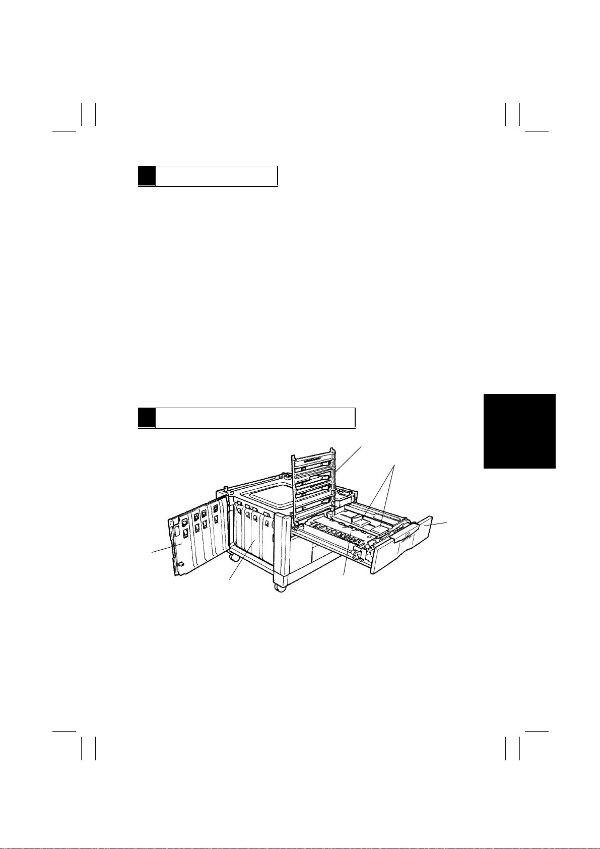
2 COMPONENT IDENTIFICATION
6
5
1. Upper Guide Plate Assy
2. Front/Rear Edge Guide Plates
3. Duplex Unit
4. Trailing Gate Unit
5. Vertical Transport Unit
6. Lower Left Door
M-1
2
3
4
1174M015AA
Page 6
FrameMaker Ver.5.5(PC) PF-6D/AD-11 OPTION FOR EP1054/EP1085/EP2030
98.06.08
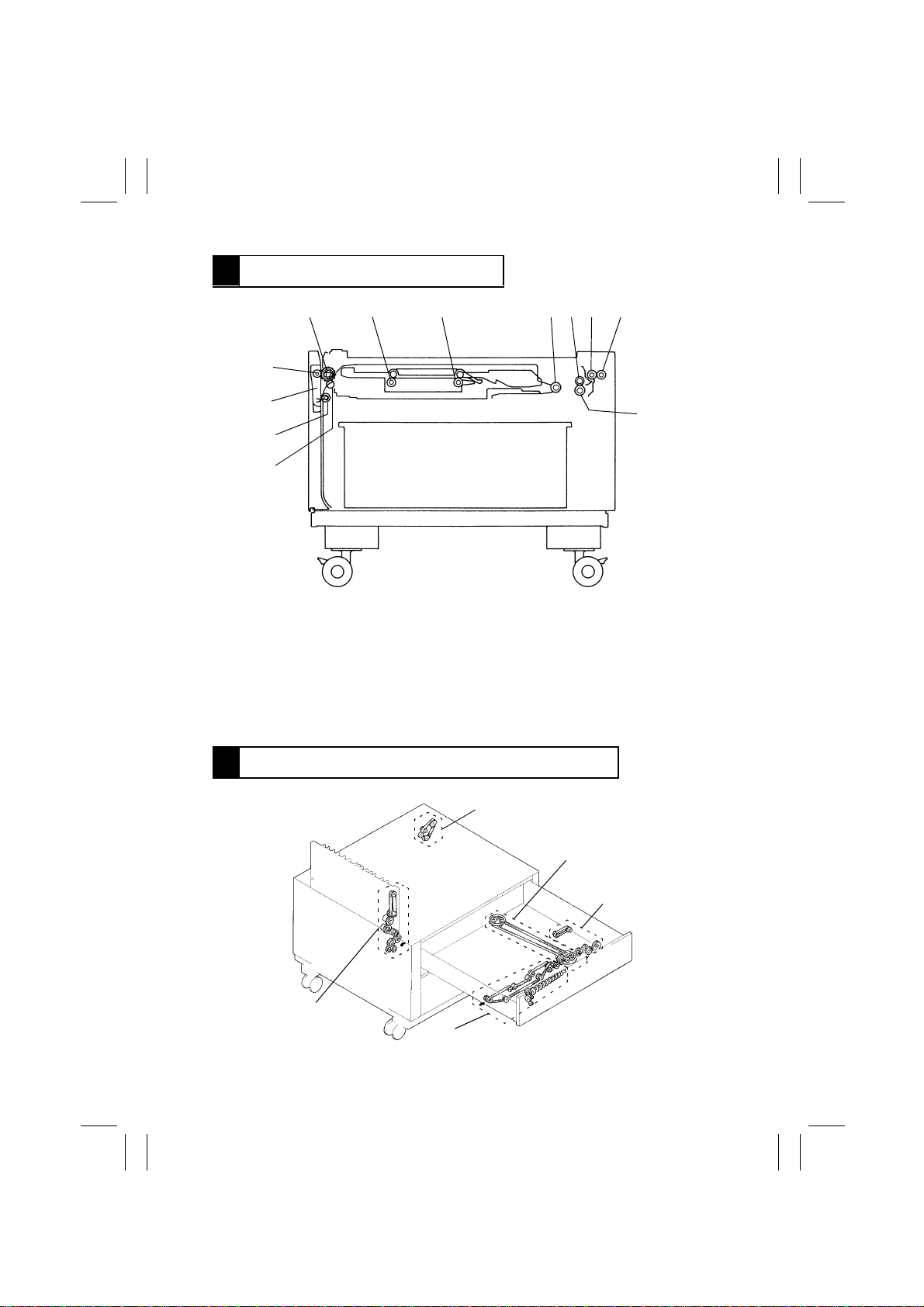
3 CROSS-SECTIONAL VIEW
1 2 3 456 7
12
11
10
9
1. Paddle Roller/Duplex Vertical Transport
Roller
2. Trailing Gate Unit Gate 2 Transport
Roller
3. Trailing Gate Unit Gate 1 Transport
Roller
4. Paper Take-Up Roll
5. Feed Roll
6. Vertical Transport Roller (Drive)
7. Vertical Transport Roller (Driven)
8. Separator Roll
9. Roll B
10. Slip Roll
11. Release Lever
12. Roll A
4 DRIVE SYSTEM COMPONENT LAYOUT
Vertical Transport
Drive Section
Front/Rear Edge Guide
Plate Drive Section
8
4425M223AA
Duplex Unit Vertical
Transport Drive Section
Trailing Gate Drive Section
M-2
Duplex Unit Paper
Take-Up Drive Section
4425M226AA
Page 7
FrameMaker Ver.5.5(PC) PF-6D/AD-11 OPTION FOR EP1054/EP1085/EP2030
98.06.08
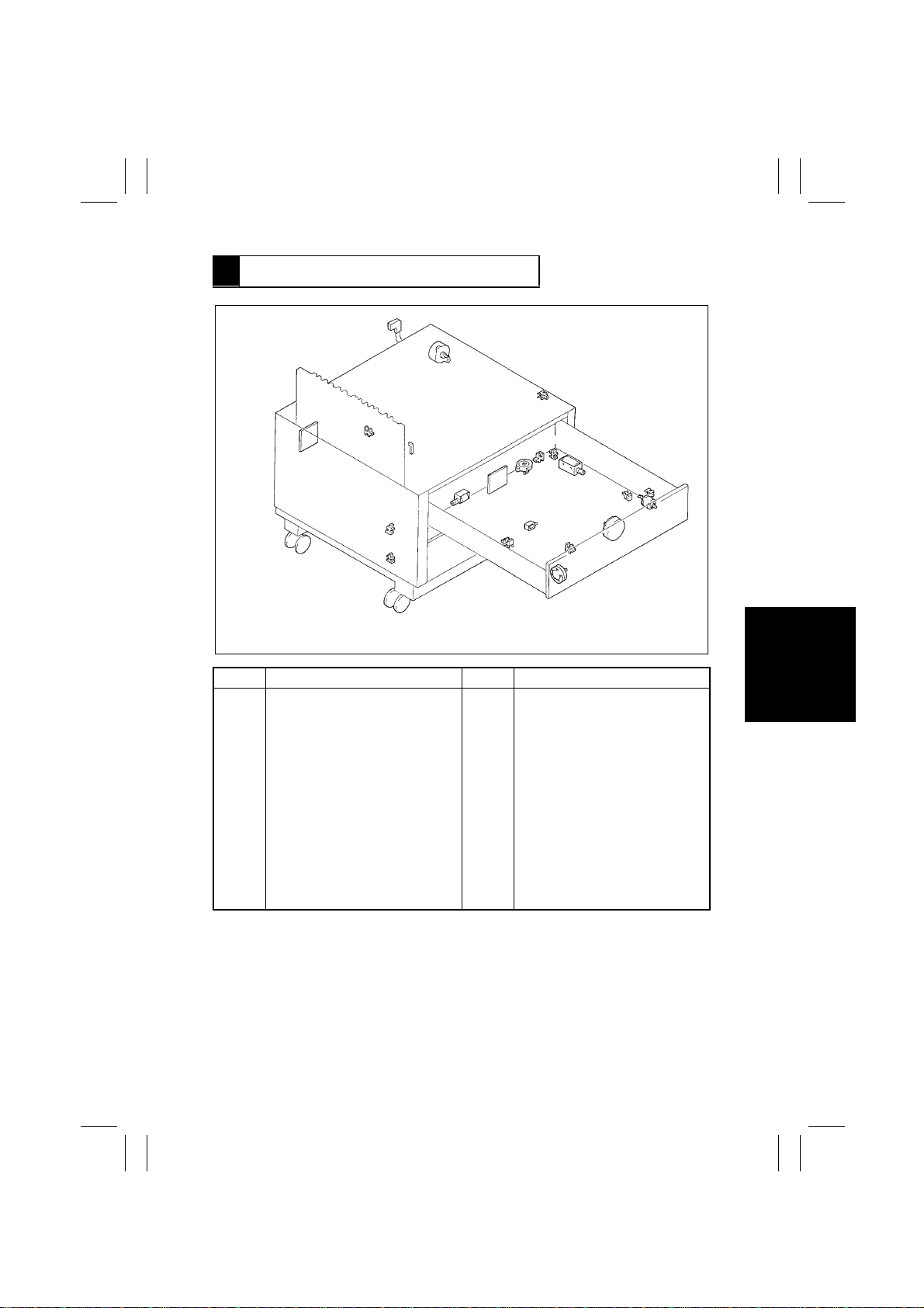
5 ELECTRICAL PARTS LAYOUT
M21
PC12
PWB-A
PC13
PC11
Symbol Name Symbol Name
CL31
M21
M31
M32
M33
PC8
PC9
PC10
PC11
PC12
Duplex Unit Paper Take-Up Clutch
Vertical Transport Motor
Duplex Unit Drive Motor
Gate Motor
Front/Rear Edge Guide Drive
Motor
Duplex Unit Gate Home Position
Sensor
Front/Rear Edge Guide Plate
Home Position Sensor
Middle Left Door Sensor
Lower Left Door Sensor
Duplex Unit Vertical Transport
Sensor
SL31
PC13
PC14
PC15
PC16
PC17
PC18
PWB-A
PWB-G
SL31
SL32
SL33
PC17
PC18
PC9
M33
PWB-G
PC14
Duplex Unit Tur n over Path Sensor
Duplex Unit Paper Entry Sensor
Duplex Unit Paper Empty Sensor
Duplex Unit Paper Take-Up
Sensor
Vertical Transport Sensor 3
Lower Right Door Sensor
Master Board
Duplex Unit Master Board
Duplex Unit Gate Switching
Solenoid
Duplex Unit Rear Finger Solenoid
Duplex Unit Pick-Up Solenoid
SL32
SL33
PC15
PC8
M31
M32
PC16
CL31
4481M003AA
M-3
Page 8
FrameMaker Ver.5.5(PC) PF-6D/AD-11 OPTION FOR EP1054/EP1085/EP2030
98.06.08
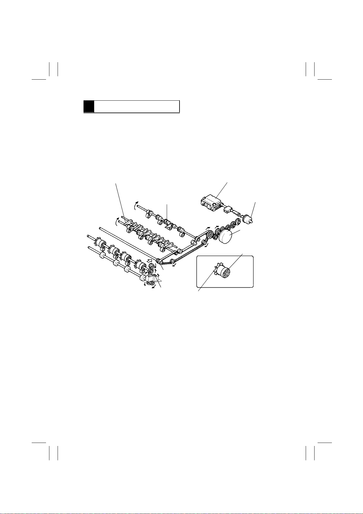
6 DUPLEX UNIT DRIVE
Duplex Unit Drive Mechanism
1.
•
Duplex Unit Drive Motor drives the Trailing Gate Unit and Duplex Unit Vertical Transport
Section through gears, transport belts and rollers.
•
Duplex Unit Paper Take-Up Clutch couples motor drive force to the paper take-up section.
•
When the Duplex Unit is slid into the Cabinet, Pulley Gear 1 meshes with Gear 1 and the
drive is transmitted to the Transport Section.
•
The figure below shows the Duplex Unit drive train.
Trailing Gate Switching Lever
Duplex Unit
Rear Finger
Pulley Gear 1
Gear 1
•
The Paddle Roller and Duplex Unit Vertical Transport Roller are assembled in one unit.
Paddle Roller
Paper Take-up Assy
Duplex Unit Paper
Take-Up Clutch CL31
Duplex Unit
Drive Motor M31
Duplex Unit Vertical
Transport Roller
4425M202AA
M-4
Page 9

FrameMaker Ver.5.5(PC) PF-6D/AD-11 OPTION FOR EP1054/EP1085/EP2030
98.06.08
2. Duplex Unit Drive Motor Control
A DC motor is used for the Duplex Unit Drive Motor. The Remote signal from pin 31 of IC1G
of the Duplex Unit Master Board energizes and deenergizes the Duplex Unit Drive Motor.
M31
Energized (forward) L
Deenergized (stopped) H
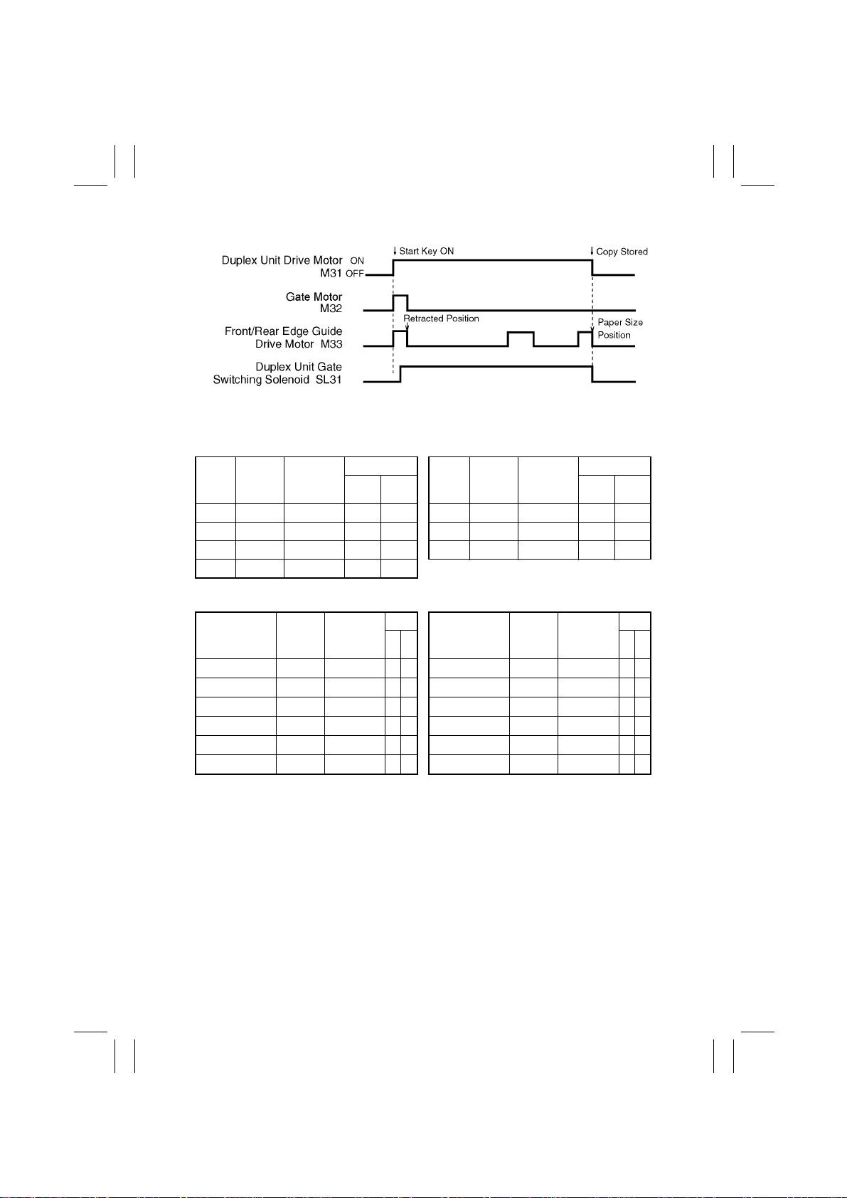
3. Duplex Unit Drive Motor Energization Timing
The motor is synchronized with the Main Drive Motor.
4. Duplex Unit Drive Motor Deenergization Timing
•
When a copy is to be stored in the Duplex Unit, the motor is briefl y deenergized after the
storage sequence has been completed. [The timing varies for different paper sizes, as
timed after the trailing edge of the paper moves past the Duplex Unit Trailing Edge Sensor (which goes HIGH).] It is then reenergized for the Duplex paper take-up sequence.
•
At the end of the copy process, the motor is deenergized after 1st Paper Exit Sensor has
detected the trailing edge of the paper. (It is synchronized with the Main Drive Motor.)
IC1G
31
M-5
Page 10
FrameMaker Ver.5.5(PC) PF-6D/AD-11 OPTION FOR EP1054/EP1085/EP2030
98.06.08
7 DUPLEX UNIT VERTICAL TRANSPORT SECTION
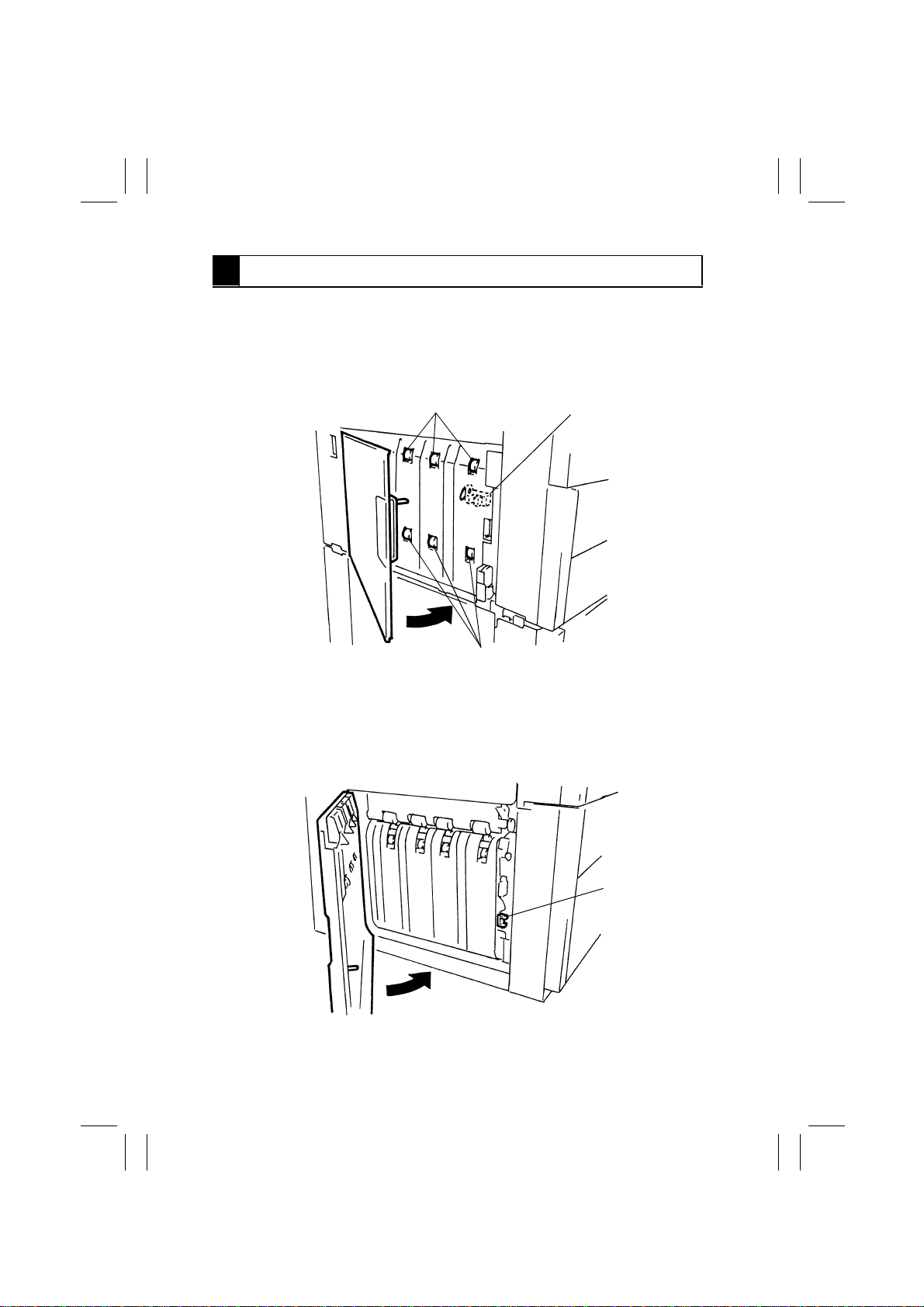
7-1. Middle Left Door Detection
•
When the Middle Left Door is closed, the Light Blocking Plate attached to t he Door bloc ks
the Middle Left Door Sensor installed in the Duplex Unit Vertical Transport Section of the
copier.
Duplex Unit Vertical
Transport Roller 1
Middle Left Door Sensor (PC10)
Duplex Unit Vertical
Transport Roller 2
4444M020AA
7-2. Lower Left Door Detection
•
When the Lower Left Door is closed, the Light Blocking Plate att ached to the Door b loc ks
the Lower Left Door Sensor installed in the Duplex Cabinet.
Lower Left Door
Sensor (PC11)
4444M021AA
M-6
Page 11
FrameMaker Ver.5.5(PC) PF-6D/AD-11 OPTION FOR EP1054/EP1085/EP2030
98.06.08
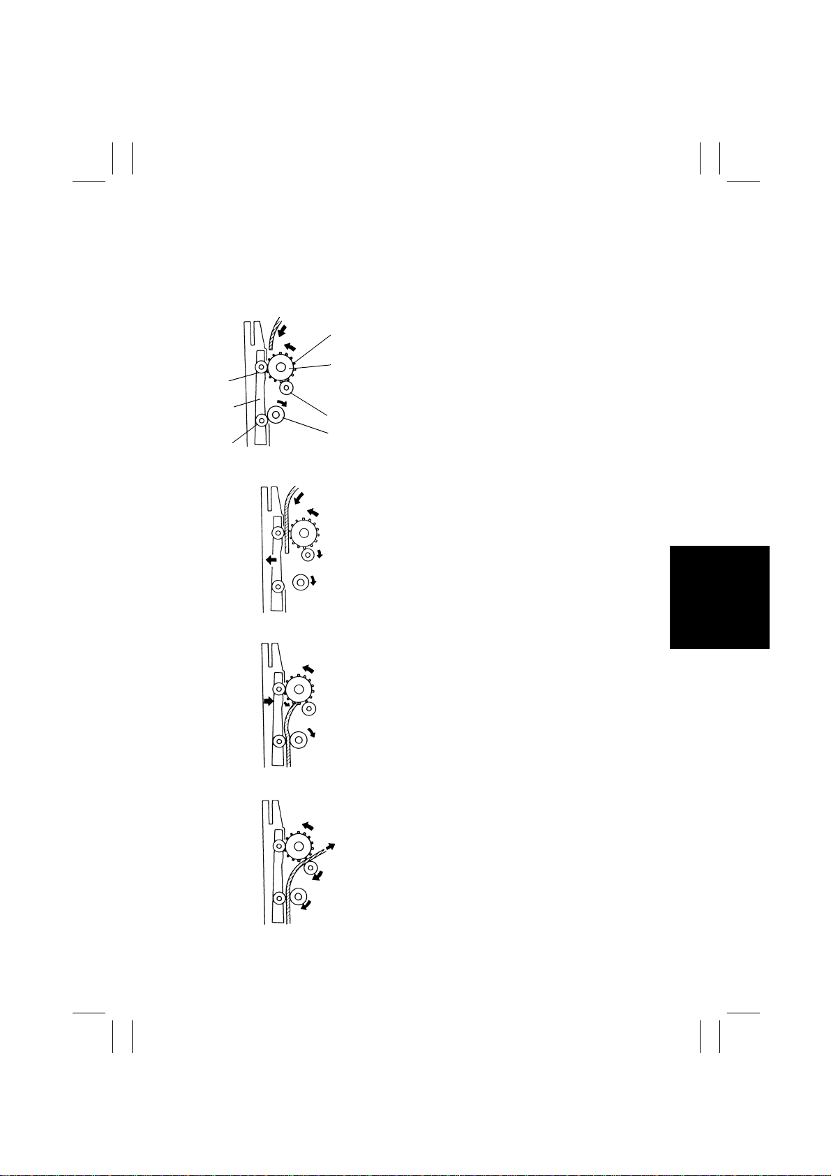
7-3. Duplex Unit Turnover Mechanism
•
The Duplex Unit Turnover Section first sends the paper to the Duplex Unit Vertical Transport Section and then switches the direction of paper travel with the Duplex Unit Drive
Motor to send the paper to the T railing Gate Unit.
•
Details of the turnover operation is as follows.
1. Paper is transferred from the Fusing
Section to the Duplex Unit Vertical
Transport Section. The Duplex Unit Vertical Transport Roller, Roll A, Slip Roll
and Roll C turn in the direction of the
arrow.
2. The Duplex Unit Vertical Transport
Roller and Roll A advance the paper
downward. The Release Lever moves in
the direction of the arrow, disengaging
Roll C from the Slip Roll.
Roll A
Release
Lever
Roll C
Paper
4425M203AA
Paddle
Roller
Duplex Unit
Vertical
Transport
Roller
Roll B
Slip roll
4425M204AA
4425M205AA
4425M206AA
3. As the trailing edge of the paper moves
past the Vertical Transport Roller and
Roll A, the Paddle Roller catches the
trailing edge and switches its direction of
travel. The Release Le ver returns to its
original position to press Roll C against
the Slip Roll, allowing the paper to move
upward.
4. The paper is sent to the Trailing Gate
Unit by the Duplex Unit Vertical Transport Roller/Roll B and Slip Roll/Roll C.
M-7
Page 12
FrameMaker Ver.5.5(PC) PF-6D/AD-11 OPTION FOR EP1054/EP1085/EP2030
98.06.08
8 COPY STORAGE
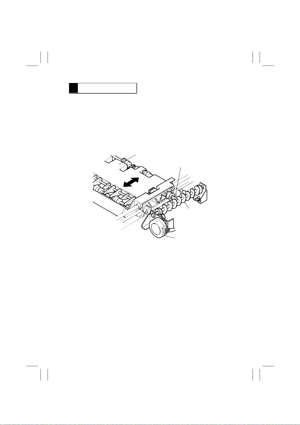
8-1. Trailing Gate Unit Moving Mechanism
1. Trailing Gate Unit Moving Operation
The Trailing Gate Unit is moved as necessary to store paper of different sizes.
•
The Trailing Gate Unit is moved as drive from the Gate Motor is transmitted via a gear
train to the Screw Cam and Screw Pin located at the front of the Trailing Gate Unit.
•
This is done to enhance the Unit’s paper storage performance.
•
The Trailing Gate Uni t moves to its home position (equivalent to A4 crosswise position) if
there is no copy left in Storage when Pow er Switch of the copier is turned ON, the Duplex
Unit is slid into position, or the Front Door of the copier is swung open and closed.
Trailing Gate Unit
Screw Pin
Screw Cam
4425M208AA
Gate Motor M32
2. Gate Motor Control
•
At the same time when the Start Ke y is pressed, the Gate Motor is energized to move the
Trailing Gate Unit to the position for the paper size selected.
•
When the 2-sided copy mode is canceled, the Gate Motor is energized to return the Trailing Gate Unit back to the home position.
•
The Gate Motor, a stepping motor, is controlled by the signals from pins 56, 57, 61 and
62 of IC1G of Duplex Unit Master Board.
•
The order of turning ON the signals determines the turning direction of the Gate Motor.
M-8
Page 13
FrameMaker Ver.5.5(PC) PF-6D/AD-11 OPTION FOR EP1054/EP1085/EP2030
98.06.08
8-2. Trailing Gate Switching Mechanism
1. Trailing Gate Switching Operation
•
When paper is to be stored in the Duplex Unit, the Trailing Gate Switching Lever is operated as necessary according to the paper size to switch the Trailing Gat e between Gate 1
and Gate 2.
•
The Trailing Gate Switching Lever is operated by Duplex Unit Gate Switching Solenoid
which is energized or deenergized according to the paper size to select Gate 1 or Gate 2
as shown in Table 1 on the next page.
•
Duplex Unit Gate Switching Solenoid is operated at the same time when the paper takeup sequence starts.
•
When the paper to be stored is 301 mm long or more, Duplex Unit Gate Switching Solenoid is energized to swing open the Trailing Gate Switching Lever to allow the paper
through Gate 2.
•
When the paper to be stored is 300 mm long or less, Duplex Unit Gate Switching Solenoid is deenergized, allowing the paper through Gate 1.
Duplex Unit Gate Switching Solenoid (SL31)
Trailing Gate 2
Trailing
Gate 1
Trailing Gate
Switching Lever
4425M212AA
M-9
Page 14
FrameMaker Ver.5.5(PC) PF-6D/AD-11 OPTION FOR EP1054/EP1085/EP2030
98.06.08
2. Trailing Gate Unit Travel Distance/Switching Operation
Table1 Metric Areas
Paper
Size
Length
(mm)
B5C 182 –28
A5L 210 0
A4C 210 0
B5L 257 +47
Trave l
Distance
(mm)
Gate
12 12
❍
– A4L 297 +87
❍
– B4L 364 +19 –
❍
– A3L 420 +175 –
❍
–
Size
Paper
Length
(mm)
Trave l
Distance
(mm)
4444T20MCB
Gate
❍
–
❍
❍
Inch Areas
Size
10-1/2”
×
10”
×
8-1/2”
5-1/2”
×
8-1/2” 215.9 +6
11”
×
8”
10”
×
8”
10-1/2” 266.7 +57
✽
Gate 1 … The Switching Lever remains stationary, guiding paper toward Gate 1.
✽
Gate 2 … The Switching Lever swings up to guide paper through Gate 2 into Storage.
✽
Tra vel distance … The Trailing Gate Unit moves in the “+” direction when it slides toward
Paper
Length
(mm)
203.2 –7
×
8”
8” 203.2 –7
215.9 +6
254 +44
Travel
Distance
(mm)
the Paddle Roller and in the “–” direction when it slides toward the
Paper Take-Up Unit of the Duplex in reference to its home position.
Gate
12 12
❍
–
❍
– 8-1/4”×13” 330.2 –15 –
❍
–
❍
– 8-1/2”×14” 355.6 +11 –
❍
–
❍
– 11”×17” 431.8 +87 –
Size
8-1/2”×11”
8-1/2”×13”
9”×14”
Paper
Length
(mm)
279.4 +69
330.2 –15 –
355.6 +11 –
Travel
Distance
(mm)
M-10
Gate
❍
–
❍
❍
❍
❍
❍
Page 15

FrameMaker Ver.5.5(PC) PF-6D/AD-11 OPTION FOR EP1054/EP1085/EP2030
98.06.08
8-3. Front/Rear Edge Guide Plate Drive Mechanism
1. Front/Rear Edge Guide Plate Drive Operation
•
The Front/Rear Guide Plates in the Duplex Unit align the front and rear edges of the
paper being stored in the Duplex Unit.
•
The Rear Edge Guide Plate is moved to the front by the Front/Rear Edge Guide Drive
Motor through a gear and belt. The Front Edge Guide Plate makes a flipping motion as
the Cam is turned by the belt from the Front/Rear Edge Guide Drive Motor.
•
Front/Rear Edge Guide Drive Motor turns in steps, each step moving the Rear Edge
Guide Plate a distance of about 0.4 mm in respect to the position where Front/Rear Edge
Guide Plate Home Position Sensor is blocked. Front/Rear Edge Guide Drive Motor is
energized to move the Plate up to the corresponding paper size position.
Front/Rear Edge Guide
Drive Motor M33
Rear Edge Guide Plate
Front Edge Guide Plate
Cam
4425M213AA
2. Retracted Position
•
The Front Edge Guide Plate is tilted by the Cam.
•
The Rear Edge Guide Plate will move, according to the paper size , to one of the six positions each of which is located at a position at least +4mm greater than the paper width.
172mm 228mm 284mm
Light Blocking
Plate
305mm249mm193mm
4425M214AA
M-11
Page 16

FrameMaker Ver.5.5(PC) PF-6D/AD-11 OPTION FOR EP1054/EP1085/EP2030
98.06.08
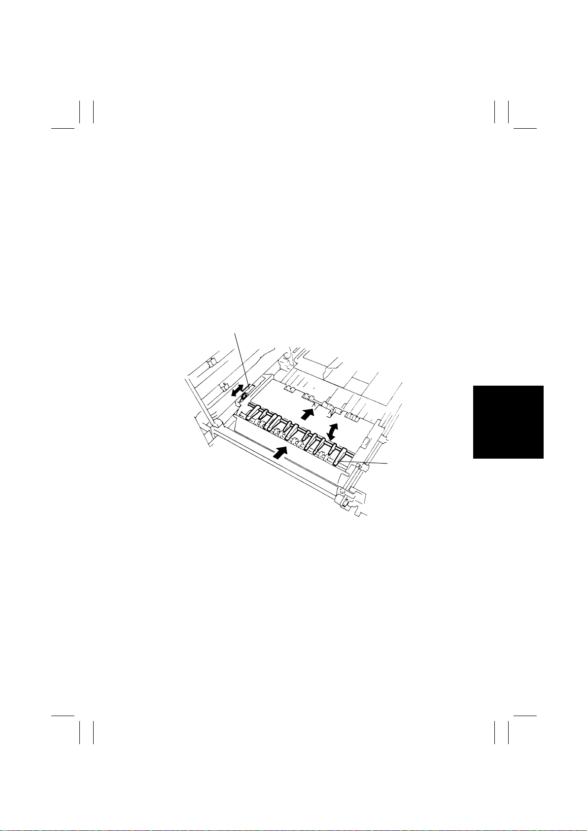
3. Operation of the Front/Rear Edge Guide Plates (for A4L)
<At Home Position>
The Front/Rear Edge Guide Plates are located at a position where the Front/Rear Edge Guide Plate
Home Position Sensor is blocked.
4425M215AA
<When storing and taking up a copy>
Select the 2-sided copy mode and press the Start Key.
Front/Rear Edge Guide Drive Motor turns forward.
The Cam moves the Front Edge Guide Plate to a retracted (stand-by) position. The Rear Edge Guide
Plate moves to the stand-by position (paper size position + approx. 4 mm toward rear).
Approx. 4mm or more
4425M216AA
After the trailing edge of the paper to be stored in the Duplex Unit has unblocked Duplex Unit Trailing
Edge Sensor (H), Front/Rear Edge Guide Drive Motor turns forward to move the Front and Rear Edge
Guide Plates to the exact paper size positions.
4425M217AA
Duplex paper take-up operation starts when the Start Key is pressed.
When Duplex Unit Paper Empty Sensor is unblocked (H), Front/Rear Edge Guide Drive Motor turns
backward, returning the Rear Edge Guide Plate to the positi on where it previously blocked Front/Rear
Edge Guide Plate Home Position Sensor (L).
M-12
Page 17

FrameMaker Ver.5.5(PC) PF-6D/AD-11 OPTION FOR EP1054/EP1085/EP2030
98.06.08
4. Front/Rear Edge Guide Drive Motor Control
<When storing a copy>
•
Upon pressing the Start Key, Front/Rear Edge Guide Plate Drive Motor turns forward,
moving the Front/Rear Edge Guide Plates to the stand-by position.
•
As the paper to be stored has passed Duplex Unit Trailing Edge Sensor (H), the Front
Edge Guide Plate is moved to the alignment position by the Cam. The Rear Edge Guide
Plate is moved to the paper size position.
<When taking up a copy>
•
When Duplex Unit Paper Empty Sensor is unblocked (H) after a copy has been taken up
from the Duplex Unit, the Rear Edge Guide Plate returns to the position where it blocks
Front/Rear Edge Guide Plate Home Position Sensor (L).
•
Front/Rear Edge Guide Plate Drive Motor is a stepping motor, which is driven by the output signals from pins 35 to 38 of IC1G of Duplex Unit Master Board.
•
The output order of the signals determines the motor direction.
M-13
Page 18

FrameMaker Ver.5.5(PC) PF-6D/AD-11 OPTION FOR EP1054/EP1085/EP2030
98.06.08
9 DUPLEX PAPER TAKE-UP UNIT
9-1. Leading Edge Guide Plate and Duplex Paper Take-Up Drive
Mechanism
•
Copies stored in the Duplex Unit are taken up and fed back into the copier by the Duplex
Take-Up Roll and Feed Roll which are driven via Duplex Unit Paper Take-Up Clutch by
the Duplex Unit Drive Motor. The top copy is separated from the remaining ones by a
paper separating mechanism with a torque limiter.
•
The Leading Edge Guide Arms align the leading edge of the copy being stored in the
Duplex Unit.
•
When Duplex Unit Pick-Up Solenoid is energized to begin a paper take-up sequence, the
Leading Edge Guide Arms are unlocked by way of the Retraction Lever. At the same
time, the Duplex Paper Take-Up Roll is pressed down against the copy to take it up.
Duplex Unit Pick-Up
Solenoid SL33
Retraction Lever
Slide Plate
Leading Edge Guide Arms
Duplex Unit Drive Motor M31
M-14
Duplex Unit Paper
Take-Up Clutch CL31
4425M240AA
Page 19

FrameMaker Ver.5.5(PC) PF-6D/AD-11 OPTION FOR EP1054/EP1085/EP2030
98.06.08
<When storing a copy>
•
When a copy is to be stored in the Duplex Unit, Duplex Unit Pick-Up Solenoid is deenergized to release, by way of the Retraction Lever, the Duplex Paper Take-Up Roll fr om the
copy or copies already in the Duplex Unit.
•
At the same time, the Leading Edge Guide Arms are locked into position by parts A of the
Slide Plate which meet the tabs on the Guide Plate, thereby aligning the leading edge of
the copy to be stored in the Duplex Unit.
Duplex Unit Pick-up
Paper Take-up Roll
Solenoid SL33
Slide Plate
Leading Edge
Guide Arm
Leading Edge
Guide Arm
A
4425M219AA
Leading Edge Guide Arm
4425M220AA
<When taking up a copy>
•
When a copy is to be taken up from the Duplex Unit, Duplex Unit Pick-Up Solenoid is
energized to lower the Retraction Lever and the Duplex Paper Take-Up Roll is pressed
against the copy in the Duplex Unit by spring force.
•
At the same time, the Leading Edge Guide Arms are unlocked from part A of the Slide
Plate.
•
When the copy is taken up and fed in, the leading edge of the copy pushes up the Leading Edge Guide Arms in the direction of the arrow.
M-15
4425M222AA4425M221AA
Page 20

FrameMaker Ver.5.5(PC) PF-6D/AD-11 OPTION FOR EP1054/EP1085/EP2030
98.06.08
9-2. Duplex Paper Take-Up Drive Control
1. Operation Timing of Duplex Unit Pick-Up Solenoid and Duplex Unit Paper Take-up
Clutch (Two 2-sided copies of A4C paper, using Duplexing/Automatic Document
Feeder)
4481T22MCB
2. Paper Take-Up Retry Control
•
If the paper to be taken up does not block Duplex Unit Paper Take-Up Sensor within a
given period of time, the paper take-up cycle starts again after Duplex Unit Pick-Up Solenoid and Duplex Unit Paper Take-Up Clutch are deenergized.
•
A paper misfeed results if a sheet of paper does not reach the Duplex Unit Paper TakeUp Sensor even after three paper take-up sequences.
NOTE
The paper take-up retry sequence is not performed in the Time Saver mode.
M-16
4481T07MCC
Page 21

FrameMaker Ver.5.5(PC) PF-6D/AD-11 OPTION FOR EP1054/EP1085/EP2030
98.06.08
9-3. Paper Take-Up Operation
1. Normal Mode
<Normal Mode with A4C Paper>
Press the Start Key to start paper take-up.
Duplex Unit Pick-Up Solenoid: Energized
Duplex Unit Paper Take-Up Clutch: Energized
The leading edge of the paper blocks Vertical Transport Sensor 3 (L).
Duplex Unit Pick-Up Solenoid and Duplex Unit Paper Take-Up Clutch: Deenergized
The trailing edge of the paper moves past Duplex Unit Paper Take-Up Sensor (H).
NO
Front/Rear Edge Guide Drive Motor is energized and the Front/Rear Edge Guide Plates return to the
home position.
Is the Duplex Unit empty?
YES
M-17
Page 22

FrameMaker Ver.5.5(PC) PF-6D/AD-11 OPTION FOR EP1054/EP1085/EP2030
98.06.08
2. Time Sa ver Mode
•
In the Time Saver mode, the copies stored in the Duplex Unit are taken up and fed back
into the copier in a different order from when in the normal mode. When the number of
copies remaining to be stored in the Duplex Unit becomes N, that copy is immediately
taken up and fed back to the copier and the subsequent ones are taken up each time
they have just been stored in the Duplex Unit. This saves a given amount of time in the
overall 2-sided copying cycle, which would otherwise be lost if Duplex take-up motion is
started after all copies have been stored.
•
The Time Saver mode is set only when the Automatic or Duplexing Document Feeder is
being used [in the standard mode (not in the Mixed Original Detection mode) with fullsize magnification and using paper less than 297 mm long].
•
When Duplex Unit Rear Finger Solenoid is energized, it turns the Duplex Unit Rear Finger so that the Finger presses the copy or copies stored in the Duplex Unit.
•
When all copies are fed out of the Duplex Unit, the Duplex Unit Rear Finger returns to its
home position.
No. Paper Length Time Saver Mode
1 139 mm ~ 257 mm
2 258 mm ~ 297 mm
The number of copies remaining to be stored in the Duplex Unit
is 4.
The number of copies remaining to be stored in the Duplex Unit
is 3.
Duplex Unit Rear Finger Solenoid
SL32
Duplex Unit Rear Finger
M-18
4425M225AA
Page 23

FrameMaker Ver.5.5(PC) PF-6D/AD-11 OPTION FOR EP1054/EP1085/EP2030
98.06.08
<Operation in Time Saver Mode: A4 crosswise paper, 10 copies>
The trailing edge of the sixth copy moves past Duplex Unit Paper Entry Sensor (H).
The Front/Rear Edge Guide Plates move to the set paper size position to align the copy.
At the same time, Duplex Unit Rear Finger Solenoid is energized and the Duplex Unit Rear Finger
presses the copies stored in the Duplex Unit.
The trailing edge of the 7th copy moves past Duplex Unit Paper Entry Sensor (H). (Each of
the 7th and subsequent copies is taken up and fed back into the copier each time it has
just been stored.)
The Front/Rear Edge Guide Plates move to the set paper size position to align the copy.
Duplex paper take-up sequence starts.
Duplex Unit Pick-Up Solenoid is energized.
Duplex Unit Paper Take-Up Clutch is energized.
The leading edge of the copy blocks V e rtical Transport Detection Sensor 3 (L). At the
same time, Duplex Unit Pick-Up Solenoid and Duplex Unit Paper Tak e -Up Clutch are
deenergized and the Front/Rear Edge Guide Plates move to the stand-by position.
NO
Have all copies been taken up for Time Saver?
After all copies for Time Saver have been taken up and fed in, the copies previously stored in the
Duplex Unit are taken up and fed in, one by one.
When all copies have been taken up from the Duplex Unit, the Duplex Unit Rear Finger returns to the
home position.
Duplex Unit Paper Empty Sensor, which has been in the blocked (L) state, is unblocked (H).
Front/Rear Edge Guide Drive Motor is energized and the Front/Rear Edge Guide Plates return to their
home positions.
YES
M-19
Page 24

FrameMaker Ver.5.5(PC) PF-6D/AD-11 OPTION FOR EP1054/EP1085/EP2030
98.06.08
10 VERTICAL TRANSPORT SECTION
1. Vertical Transport Drive Mechanism
•
V ertical Transport Motor drives the Transport Rollers via a belt to send the paper from the
Duplex Unit to the copier.
Vertical T ransport Roller
V ertical T r ansport
Motor M21
4425M250AA
2. Vertical Transport Motor Control
•
The Vertical Transport Motor, a stepping motor , is driven b y the signals from pins 1, 2, 17
and 4 of IC9A on the cabinet’s Master Board which is controlled by the copier Master
Board. The drive signals are fed into 2 windings in the motor.
M-20
4481T23MCB
Page 25

FrameMaker Ver.5.5(PC) PF-6D/AD-11 OPTION FOR EP1054/EP1085/EP2030
98.06.08
11 EXIT SECTION
1. Exit/Duplex Switching Mechanism
•
The paper path is switched by the Exit/Duplex Switching Plate which is operated by the
Exit/Duplex Solenoid.
•
The paper path is switched according to the copying mode as detailed below.
Copying Mode Exit/Duplex Solenoid SL61
Normal Deenergized
2-sided copy (when 1-sided copy is fed into
Duplex)
Operation in 2-Sided Copying Mode
The Front/Rear Edge Guide Plates and
Trailing Gate Unit move according to the
set paper size.
Energized
Select the 2-sided copying mode.
Press the Start Key.
4425M224AA
M-21
A given period of time after a TRON signal has been output, Exit/Duplex Solenoid is energized to feed the copy into
the Duplex Unit.
The paper is fed into the Duplex Unit.
Exit/Duplex Solenoid is deenergized a
given period of time after Synchronizing
Roller Clutch has been deenergized.
Page 26

FrameMaker Ver.5.5(PC) PF-6D/AD-11 OPTION FOR EP1054/EP1085/EP2030
98.06.08
2. Exit/Duplex Solenoid Control
•
Exit/Duplex Switching Solenoid is energized and deenergized by the Exit/Duplex Switching Solenoid Remote signal from pin 43 of IC5A of the copier Master Board.
<Exit/Duplex Switching Solenoid Energization Timing>
•
Exit/Duplex Switching Solenoid is energized at a predetermined time after the TRON (L)
signal has been output.
<Exit/Duplex Switching Solenoid Deenergization Timing>
•
Exit/Duplex Switching Solenoid is deenergized at a predetermined time after Synchronizing Roller Clutch has been deenergized.
•
For a multi-copy cycle, it is deenergized at a predetermined time after Synchronizing
Roller Clutch has been deenergized for the last paper.
M-22
Page 27

FrameMaker Ver.5.5(PC) PF-112 OPTION FOR EP1054/EP1085/EP2030
98.06.08
DIS/REASSEMBLY,
ADJUSTMENT
Page 28

FrameMaker Ver.5.5(PC) PF-6D/AD-11 OPTION FOR EP1054/EP1085/EP2030
98.06.08
1 DISASSEMBLY
1-1. Removal of Exterior Parts
1
2
10
1174D003AA
screws.
screws.
3
9
5
4
No. Part Name Removal Procedure
1 Lower Right Door After removing Rear Right Cover, remove 2 screws.
2 Rear Right Cover Remove 2 screws.
3 Lower Right Cover After removing Front Right and Rear Right Covers, remove 2
4 Front Right Cover Remove 2 screws.
5 Lower Front Cover After removing Front Left and Right Covers, remove 2 screws.
6 Front Left Cover Remove 2 screws.
7 Middle Left Door Remove 4 screws.
8 Lower Left Cover After removing Front Left and Rear Left Covers, remove 2
9 Rear Left Cover Remove 2 screws.
10 Rear Cover Remove 2 screws.
7
8
4479D008AA
6
D-1
Page 29

FrameMaker Ver.5.5(PC) PF-6D/AD-11 OPTION FOR EP1054/EP1085/EP2030
98.06.08
1-2. Removal of Duplex Unit Drive Motor Assy
1. Slide out and remove the Duplex Unit.
2. Remove 4 screws and the Duplex Unit exterior
cover.
3. Remove 2 screws and the Duplex Unit interior
cover.
4425D231AA
4. Remove 2 screws and the cover.
4425D201AA
5. Remove 4 screws and the Duplex Unit Drive Motor
Assy .
4425D202AA
1-3. Removal of Paper Take-Up Unit
1. Remove the Duplex Unit Drive Motor Assy.
2. Remove 3 screws and the PWB-G cover.
4425D203AA
3. Remove 4 screws and the Duplex Unit Paper
Take-Up Unit.
4425D204AA
D-2
Page 30

FrameMaker Ver.5.5(PC) PF-6D/AD-11 OPTION FOR EP1054/EP1085/EP2030
98.06.08
4. Remove 2 connectors. Shift the Front/Rear Edge
Guide Plate Home Position Sensor to the side and
then remove the Paper Take-Up Unit.
4425D205AA
1-4. Removal of Trailing Gate Unit
1. Remove 1 screw and the Upper Guide Plate.
4425D206AA
2. Move the Trailing Gate Unit to the left as far as it
goes by turning the Screw Cam.
3. Remove 1 screw and the Upper Guide Plate Assy.
4425D207AA
4425D208AA
4425D210AA
4. Remove the E-ring and washer. Remove the Timing Belt from the Gear.
5. Snap off two E-rings and remove the Slide Shaft.
D-3
Page 31

FrameMaker Ver.5.5(PC) PF-6D/AD-11 OPTION FOR EP1054/EP1085/EP2030
98.06.08
6. Remove 2 screws, the ground wire and t he Trailing
Gate Unit.
4425D211AA
1-5. Removal of Paper Guide Sheet
1. Remove the Trailing Gate Unit.
2. Remove 4 screws and the Paper Mounting Plate.
4425D212AA
3. Remove 2 springs.
4. Remove 2 screws and the Paper Guide Sheet.
4425D213AA
1-6. Removal of Front/Rear Guide Plate Assy
1. Remove the Paper Take-Up Unit.
2. Unplug 2 connectors.
4425D214AA
3. Remove 2 screws and then the Front/Rear Edge
Guide Plate Assy.
CAUTION
When reinstalling the Front/Rear Edge Guide Plate
Assy, positively hook the fingers into the Mounting
Plate. Align the scale with that on the Mounting Plate.
4425D215AA
D-4
Page 32

FrameMaker Ver.5.5(PC) PF-6D/AD-11 OPTION FOR EP1054/EP1085/EP2030
98.06.08
1-7. Removal of Vertical Transport Unit
1. Remove 2 screws and the Rear Left Cover.
2. Remove 4 screws and the Lower Left Door.
4425D216AA
3. Remove 5 screws and 1 connector. Slide the Vertical Transport Unit to the rear and remove it.
4425D217AA
1-8. Removal of Take-Up Roll/Feed Roll Assy
4425D218AA
4425D219AA
1. Remove the Duplex Unit Drive Motor Assy.
2. Loosen 1 screw and remove the retainer spring.
3. Remove the C-clip and Paper Take-Up Sensor
Assy.
4. Remove 1 screw and the Cover.
5. Remove 2 screws and the ground spring. Lift up
and then remove the Solenoid Mounting Plate
Assy.
CAUTION
When reinstalling the Solenoid Mounting Plate Assy,
be sure to insert the Paper Take-Up Roll/Feed Roll
Assy bracket above the Rectraction Lever.
D-5
Page 33

FrameMaker Ver.5.5(PC) PF-6D/AD-11 OPTION FOR EP1054/EP1085/EP2030
98.06.08
6. Remove 2 C-clips. Lifting up the Paper Take-Up
Roll/Feed Roll Assy, move it toward the rear and
remove.
CAUTION
When reinstalling the Paper Take-Up Roll/Feed Roll
Assy, first engage the shaft coupling at the front and
then rehook the spring.
4425D220AA
7. Remove the bushing, E-ring, bushing and spring.
4425D221AA
8. Snap off 2 E-rings, pull out the shaft and then
remove the Feed Roll.
4425D222AA
9. Remove the E-ring, bushing and then the Paper
Take-Up Roll.
4425D223AA
1-9. Removal of Separator Roll Assy
1. Remove 2 screws and then the Mounting Plate.
CAUTION
When reinstalling the Mounting Plate, align the locking
members.
4425D224AA
D-6
Page 34

FrameMaker Ver.5.5(PC) PF-6D/AD-11 OPTION FOR EP1054/EP1085/EP2030
98.06.08
2. Remove 1 C-clip and screw and then the Guide
Holder.
CAUTION
When reinstalling the screw, make sure that it is abov e
the Guide Holder.
4425D225AA
3. Remove the C-clip. Remove the Separator Roll
Assy by sliding it toward the rear and then upward.
4425D226AA
1-10. Cleaning of Vertical Transport Rollers
Using a soft cloth dampened with alcohol, wipe clean
the Transport Rollers.
4425D017AA
1-11. Cleaning of Duplex Unit Vertical Transport Roller/Slip Roll
Using a soft cloth dampened with alcohol, wipe clean
the Duplex Unit Vertical Transport Roller/Slip Roll.
4425D232AA
D-7
Page 35

FrameMaker Ver.5.5(PC) PF-6D/AD-11 OPTION FOR EP1054/EP1085/EP2030
98.06.08
1-12. Cleaning of Paper Take-Up Roll/Feed Roll/Separator Roll
1. Pull out the Duplex Unit.
2. Remove 2 screws and then the Mounting Plate
Assy .
3. Using a soft cloth dampened with alcohol, wipe
clean the Paper Take-Up Roll, Feed Roll and Separator Roll.
4425D233AA
1-13. Cleaning of Trailing Gate Unit Transport Rollers 1 & 2
1. Pull out and remove the Duplex Unit.
2. Open the Guide Plate Assy.
3. Using a soft cloth dampened with alcohol, wipe
clean the Trailing Gate Unit Transport Rollers 1 &
2.
4425D234AA
1-14. Parts Which Must Not Be Touched
Duplex Unit Pick-Up Solenoid SL33.
4425D228AA
D-8
Page 36

FrameMaker Ver.5.5(PC) PF-6D/AD-11 OPTION FOR EP1054/EP1085/EP2030
98.06.08
2 ADJUSTMENT
2-1. Adjustment of Magnetic Catch
1. Remove the Vertical Transport Unit.
2. Loosen two screws on the Magnetic Catch. Check
that each part marked with a circle in the fig. on the
left is in contact with the corresponding matching
part and then tighten the screws.
3. Swing open and close the Vertical Transport Unit
to check that each part is in contact with the other.
4425D235AA
2-2. Adjustment of Clearance Between Release Lever Assy
and Guide Plate (This adjustment must be made after the
adjustment of the Magnetic Catch has been completed.)
1. Close the Vertical Transport Assy.
2. Loosen one screw on each Release Lever Assy.
3. Move the Release Lever Assy up and down as
necessary to obtain a clearance of 1 to 3.0 mm
between the Le v e r Assy a nd Gui de Pla te. When the
specified clearance is obtained, tighten the screw.
4. Swing open the Vertical Transport Unit and turn the
4425D227AA
Paddle Roller one complete turn. Then, close the
Vertical Transport Unit and check for clearance again.
5. After the clearance has been checked, turn the
Paddle Roller to check to see if the Rolls in the
Release Lever turn.
2-3. Adjustment of Front/Rear Edge Guide Plate Timing Belt
1. Loosen two screws.
2. Hook a tension gage into the motor mounting hole
and then pull the gage in the direction of the arrow
with a force of 350 ± 50g.
3. Tighten the screws.
4444M023AA
D-9
Page 37

FrameMaker Ver.5.5(PC) PF-6D/AD-11 OPTION FOR EP1054/EP1085/EP2030
98.06.08
2-4. Alignment of Front/Rear Edge Guide Holder
Align the hole in the Front/Rear Edge Guide Plate
Holder with that in the Edge Guide Plate. Align the
hole in the Cam with another one in the Edge Guide
Plate. Fit an Allen wrench into the holes of the Cam
and Plate and screw the Holder into position.
4425D230AA
2-5. Adjustment of Trailing Gate Unit Timing Belt
1. With the tension given by the spring, tighten one
screw.
4481D001AA
2-6. Adjustment of Duplex Unit Reference Position
Requirement
•
Prepare a test chart (A3 size) as shown on the left.
Draw a line on the chart at a point 20 mm from the
right edge.
•
Dimension A on the copy should measure 20 ± 3.0
mm.
1074D089
1. Place the test chart on the Original Glass and align
the rear edge of the test chart with the reference
mark (▲). Lower the Original Cover.
2. Select 1 2 copy mode and make two copies of
the test chart in the full size mode (use A3 paper).
3. Compare the position of the reference line on the
second copy with that on the test chart.
1139D027AA
▲
D-10
Page 38

FrameMaker Ver.5.5(PC) PF-6D/AD-11 OPTION FOR EP1054/EP1085/EP2030
98.06.08
4. If the copied line deviates from the reference line,
pull out the Duplex Unit and open the Upper Guide
Assy .
5. Slide the Rear Edge Guide Plate forward. Loosen
the 2 screws securing the Front/Rear Edge Guide
Plate Assy. Adjust the position of the Assy and
then tighten the screws.
4425U305AA
NOTE
If copied width A < 17 mm, move the Front/Rear Edge
Guide Plate Assy toward the rear.
If copied width A > 23 mm, move the Assy toward the
front.
4425U306AA
2-7. Adjustment of Duplex Unit Gate Switching Solenoid SL31
Position
1. Move SL31 in the direction of the arrow and then
loosen the screws.
2. Manually place SL31 in the energized position and
check that the clearance between the Switching
Lever and round shaft measures 11 mm or more.
Check also that the Switching Lever is in tight contact with the round shaft when SL31 is in the deen-
4425M235AA
ergized position.
2-8. Adjustment of Duplex Unit Rear Finger Solenoid SL32
Position
1. Move SL32 in the direction of the arrow and then
loosen the screws.
2. Check that the Duplex Unit Rear Finger is operated
when SL32 is manually placed in the energized
position.
4425M234AA
D-11
Page 39

FrameMaker Ver.5.5(PC) PF-6D/AD-11 OPTION FOR EP1054/EP1085/EP2030
98.06.08
2-9. Adjustment of Vertical Transport Timing Belt
1. Remove the Rear Cover, Front Right Cover, Front
Left Cover, and Upper Front Cover.
2. Remove the Duplex Unit Guide Rail (Right).
3. Go to the rear of the Cabinet and, using a wrench,
loosen the hexagon screw used for adjustment of
the Vertical Transport Belt. Adjust so that the Belt
has no slack.
4425D018AA
4. Check the Belt for tension using a tension gage.
The gage should read 80 to 100 g when the Belt is
pushed to deflect 1 mm.
D-12
Page 40

FrameMaker Ver.5.5(PC) PF-112 OPTION FOR EP1054/EP1085/EP2030
98.06.08
MISFEED
DETECTION/
MALFUNCTION
DETECTION
Page 41

FrameMaker Ver.5.5(PC) PF-6D/AD-11 OPTION FOR EP1054/EP1085/EP2030
98.06.08
1 MISFEED DETECT ION
1-1. Location of Misfeed Detecting Sensors
Paper Exit Sensor
PC53
Duplex Vertical
Transport Sensor
PC12
Duplex Unit Paper
Entry Sensor PC14
Vertical Transport
Sensor 3 PC17
Duplex Unit Paper
Take-Up Sensor PC16
Duplex Unit Paper
Empty Sensor PC15
4425T202AA
1-2. Misfeed Detection Types and Detection Timings
Any of the following misfeeds occurring in the Duplex Unit is detected under the corresponding conditions and shown on the copier control panel.
Type Detection
Leading edge detection by
Duplex Unit Vertical
Transport Sensor PC12
Trailing edge detection by
Duplex Unit Vertical
Transport Sensor PC12
Leading edge detection by
Duplex Unit Paper Entry
Sensor PC14
Trailing edge detection by
Duplex Unit Paper Entry
Sensor PC14
PC12 is not blocked (L) after the lapse of a given period of
time after 1
PC12 is not unblocked (H) after the lapse of a given period of
time after PC53 has been unblocked (H).
PC14 is not blocked (L) after the lapse of a given period of
time after Duplex Unit Vertical Transport Sensor PC12 has
been blocked (L).
PC14 is not unblocked (H) after the lapse of a given period of
time (which varies with paper size) after it has been blocked
(L).
st
Paper Exit Sensor PC53 has been blocked (L).
T-1
Page 42

FrameMaker Ver.5.5(PC) PF-6D/AD-11 OPTION FOR EP1054/EP1085/EP2030
98.06.08
Type Detection
Storage Detection Duplex Unit Paper Empty Sensor PC15 is not unblocked (L)
Take-up failure detection Vertical Transport Sensor 3 PC17 is not blocked (L) after the
Take-up trailing Edge
detection
Time Saver take-up
detection
after a copy has been stored in the Duplex Unit.
lapse of a given period of time after Duplex Unit Paper TakeUp Clutch CL31 has been energized during the third paper
retry sequence.
Duplex Unit Paper Take-Up Sensor PC16 is not unblocked (H)
after the lapse of a given period of time (which varies with
paper size) after it has been blocked (L).
PC17 is not blocked (L) after the lapse of a given period of
time after CL31 has been energized for each of the copies for
Time Saver except the last.
2 MALFUNCTION DETECTION
Malfunction
Code
C0d00 F ront/Rear Edge Guide
C0d20 Trailing Gate Unit home
C0d50
C0d51 Duplex Unit Drive
Description Detecting Timing
Plate home position
detection
failure
position
detection failure
Duplex Unit Drive Motor
M31 failure to turn
Motor M31 turning at
abnormal timing
The home position is detected only in the initial
operation sequence. Front/Rear Edge Guide Plate
Home Position Sensor PC9 is not b loc ked (L) within
a given period of time after the initial operation
sequence has started (when the Power Switch is
turned ON, the Front Door is swung open and
closed, the Duplex Unit is slid into position, paper
take-up sequence from the Duplex Unit is completed, or 2-sided copy mode is canceled).
The home position is detected only in the initial
operation sequence. (When the Power Switch is
turned ON, the Front Door is swung open and
closed, the Duplex Unit is sli d into position, or the 2sided copy mode is canceled).
1. Duplex Gate Home Position Sensor PC8 is
blocked (L) at the start of the initial operation
sequence.
A. PC8 is unblocked (H) within a given period of
time.
B. PC8 is not blocked (L) within a given period of
time after it has been unblocked (H).
1. Duplex Gate Home Position Sensor PC8 is
unblocked at the start of the initial operation
sequence.
A. PC8 is not blocked (L) within a given period of
time.
The Motor Lock signal (H) is detected for a given
period of time after M31 has been energized.
The Motor Lock signal (L) is detected for a given
period of time after M31 has been deenergized.
T-2
Page 43

3568724
A
B
C
D
91
A
B
C
D
E
F
G
H
I
DWG.NO.
TITLE
MODEL
VOLTAGE
EFFECTIVE
MACHINE NO.
DATE ISSUED
4479-C003-0A
WIRING DIAGRAM
PF-6D/AD-11
From the copier
XX0201 AND ONWARD
Dec.1998
E
F
G
H
I
12345678
9
Page 44

A
B
C
D
E
F
G
H
9
8
7
I
9
8
7
6
5
4
3
6
5
4
3
2
DWG.NO.
TITLE
MODEL
1
A
B
C
D
E
F
G
H
VOLTAGE
EFFECTIVE
MACHINE NO.
DATE ISSUED
4479-C203-0A
CIRCUIT DIAGRAM PWB-A,G
AD-11/PF-6D
From the copier
XX0201 AND ONWARD
Oct.1998
I
2
1
 Loading...