

Page 1

FrameMaker Ver.5.5(PC) PF-206 OPTION FOR EP1054/EP1085/EP2030
98.06.08
PF-206
SERVICE MANUAL
10794
Page 2

FrameMaker Ver.5.5(PC) PF-206 OPTION FOR EP1054/EP1085/EP2030
98.06.08
CONTENTS
GENERAL, MECHANICAL/ELECTRICAL
1. SPECIFICATIONS ........................................................................................... M-1
2. COMPONENT IDENTIFICATION ................... ........................... ......................M-1
3. CROSS-SECTIONAL VIEW ............................................................................M-2
4. DRIVE SYSTEM ..............................................................................................M-2
5. ELECTRICAL PARTS LAYOUT ......................................................................M-3
6. VERTICAL TRANSPORT SECTION ...............................................................M-4
7. PAPER TAKE-UP/FEEDING SECTION ..........................................................M-5
7-1. Paper Take-Up Mechanism .....................................................................M-5
(1) Paper Take-Up Mechanism .............................................................M-5
(2) Paper Separating Mechanism .........................................................M-6
(3) Paper Pressure Releasing Mechanism ...........................................M-7
(4) Paper Take-Up Roll Retraction Mechanism ....................................M-7
7-2. Paper Take-Up Control ............................................................................M-8
(1) Paper Take-Up Motor Control .........................................................M-8
(2) Paper Take-Up Retry Control ..........................................................M-8
(3) Paper Take-Up Interval Control (30 cpm Copier Only) ....................M-9
(4) Double Feed Paper Take-Up Control (30 cpm Copier Only) ...........M-9
7-3. Fixed Drawer ...........................................................................................M-10
7-4. Drawer-in-Position Detection ...................................................................M-10
7-5. Drawer Paper Lift-Up Mechanism ............................................................M-11
7-6. Paper Empty Detection ............................................................................M-13
7-7. Paper Level Detection (30 cpm Copier Only) ..........................................M-14
7-8. Cabinet Paper Dehumidifying Heater (option) .........................................M-15
DIS/REASSEMBLY, ADJUSTMENT
1. DISASSEMBLY ...............................................................................................D-1
1-1. Removal of Exterior Parts ........................................................................D-1
1-2. Removal of the Guide Plates and Cover Plates ......................................D-2
1-3. Removal of Paper Take-Up Roll and Feed Roll Assy from Drawer .........D-2
1-4. Disassembly of Paper Take-Up Roll/Feed Roll Assy ...............................D-3
1-5. Removal of Separator Roll Assy ..............................................................D-4
1-6. Cleaning of Paper Take-Up Roll, Feed Roll and Separator Roll ..............D-5
1-7. Cleaning of Transport Roller ....................................................................D-5
2. ADJUSTMENT .................................................................................................D-6
2-1. Adjustment of 3rd and 4th Drawer Reference Position ............................D-6
2-2. Adjustment of Vertical Transport Timing Belt ..........................................D-7
MISFEED DETECTOIN & MALFUNCTION DETECTION
1. MISFEED DETECTION .............................. ........................... ..........................T-1
1-1. Location of Misfeed Detecting Sensors ...................................................T-1
1-2. Misfeed Detection Types and Detection Timings ....................................T-1
2. MALFUNCTION DETECTION ................................ .............................. ...........T-2
i
Page 3

FrameMaker Ver.5.5(PC) PF-112 OPTION FOR EP1054/EP1085/EP2030
98.06.08
GENERAL,
MECHANICAL/
ELECTRICAL
Page 4

FrameMaker Ver.5.5(PC) PF-206 OPTION FOR EP1054/EP1085/EP2030
98.06.08
1 SPECIFICATIONS
Name : 2 Way Paper Feed Cabinet
Type of Copy Paper : Plain and recycled paper
Paper Sizes : Upper: A5L to A3L, 5-1/2” × 8-1/2”L to 11” × 17”L
Lower: A4L to A3L, 8-1/2” × 11”L to 11” × 17”L
Paper Thickness : 60-90 g/m² or 16 to 24 Ibs.
Capacity ::500 sheets × 2 (80 g/m²)
550 sheets × 2 (20 Ibs.)
Power Source : 24 VDC, 5 VDC (supplied from copier)
Power Consumption : 80 W
Dimensions : Width … 610 mm or 24”
Weight : 35.2 kg or 77-1/2 Ibs.
Depth … 595 mm or 23-1/2”
Height … 472 mm or 18-1/2”
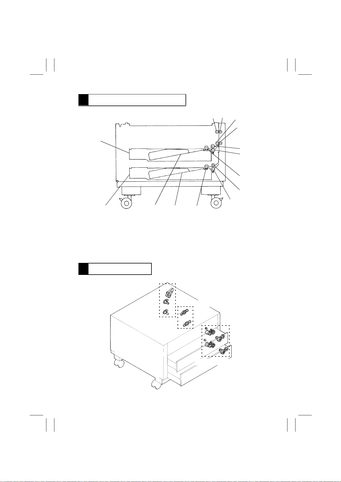
2 COMPONENT IDENTIFICATION
1
10
9
8
1. Paper Lifting Plate
2. Vertical Transport Roller 2 (Drive)
3. Vertical Transport Roller 1 (Drive)
4. Lower Right Door
5. Separator Roll/Paper Guide Plate
7
6. Paper Guide Plate
7. 4th Drawer
8. 3rd Drawer
9. Trailing Edge Stop
10. Edge Guide
2
3
4
1174M016AA
6
5
M-1
Page 5
FrameMaker Ver.5.5(PC) PF-206 OPTION FOR EP1054/EP1085/EP2030
98.06.08
3 CROSS-SECTIONAL VIEW
14
13
12
11
10
2
1
3
4
5
6
7
8
9
4425M016AA
1. Vertical Transport Roller 2 (Drive)
2. Vertical Transport Roller 2 (Driven)
3. Vertical Transport Roller 1 (Drive)
4. Vertical Transport Roller 1 (Driven)
5. 3rd Drawer Feed Roll
6. 3rd Drawer Separator Roll
7. 3rd Drawer Take-Up Roll
4 DRIVE SYSTEM
8. 4th Drawer Feed Roll
9. 4th Drawer Separator Roll
10. 4th Drawer Take-Up Roll
11. 4th Drawer Lifting Plate
12. 3rd Drawer Lifting Plate
13. 4th Drawer
14. 3rd Drawer
Vertical Transport Drive Section
Paper Take-Up Drive Section
Drawer Lift-Up Drive Section
4425M017AA
M-2
Page 6

FrameMaker Ver.5.5(PC) PF-206 OPTION FOR EP1054/EP1085/EP2030
98.06.08
5 ELECTRICAL PARTS LAYOUT
4425M018AA
Symbol Name Symbol Name
H22
M21
M22
M23
M24
M25
PC17
PC18
PC19
PC20
PC21
Cabinet Paper Dehumidifier
Heater (Option)
Vertical Transport Motor
3rd Drawer Paper Take-Up Motor
4th Drawer Paper Take-Up Motor
3rd Drawer Paper Lift-Up Motor
4th Drawer Paper Lift-Up Motor
Vertical Transpor t Sensor 3
Lower Right Door Sensor
3rd Drawer Paper Lift-Up Sensor
3rd Drawer Paper Empty Sensor
3rd Drawer Paper Take-Up
Sensor
PC22
PC23
PC24
PC25
PC26
PC27
PC28
PC29
PWB-A
Vertical Transport Sensor 4
4th Drawer Paper Lift-Up Sensor
4th Drawer Paper Empty Sensor
3rd Drawer Set Sensor
4th Drawer Set Sensor
3rd Drawer Paper Lift-Up Motor
Pulse Sensor (in M24)
4th Drawer Paper Lift-Up Motor
Pulse Sensor (in M25)
4th Drawer Paper Take-Up
Sensor
Master Board
M-3
Page 7
FrameMaker Ver.5.5(PC) PF-206 OPTION FOR EP1054/EP1085/EP2030
98.06.08
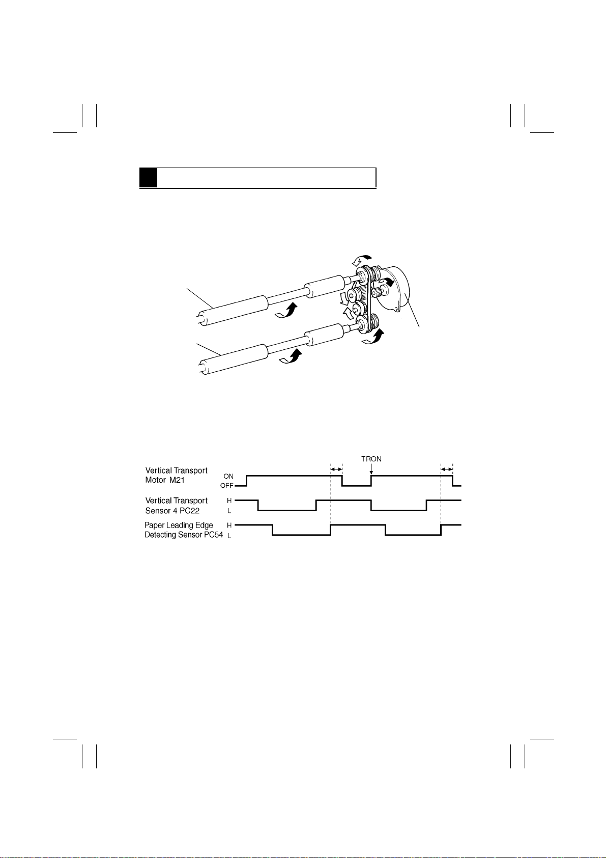
6 VERTICAL TRANSPORT SECTION
1. Vertical Transport Drive Mechanism
•
The Vertical Transport Rollers are driven by the Vertical Transport Motor.
•
The driving force of the Vertical Transport Motor is transferred through the belt to the Vertical Transport Rollers which feed the paper from the Paper Drawers to the copier .
Vertical Transport Roller 2
Vertical Transport Roller 1
2. Vertical Transport Motor Control
•
Vertical Transport Motor, which is a stepping motor, is driven by the output signals from
pins 1, 2, 17, and 4 of IC9A on the cabinet’s Master Board which is in turn controlled by
the Master Board of the copier. These signals energize the two coils in the V ertical Transport Motor.
Vertical Transport
Motor M21
4425M010AA
4479T51MCB
M-4
Page 8
FrameMaker Ver.5.5(PC) PF-206 OPTION FOR EP1054/EP1085/EP2030
98.06.08
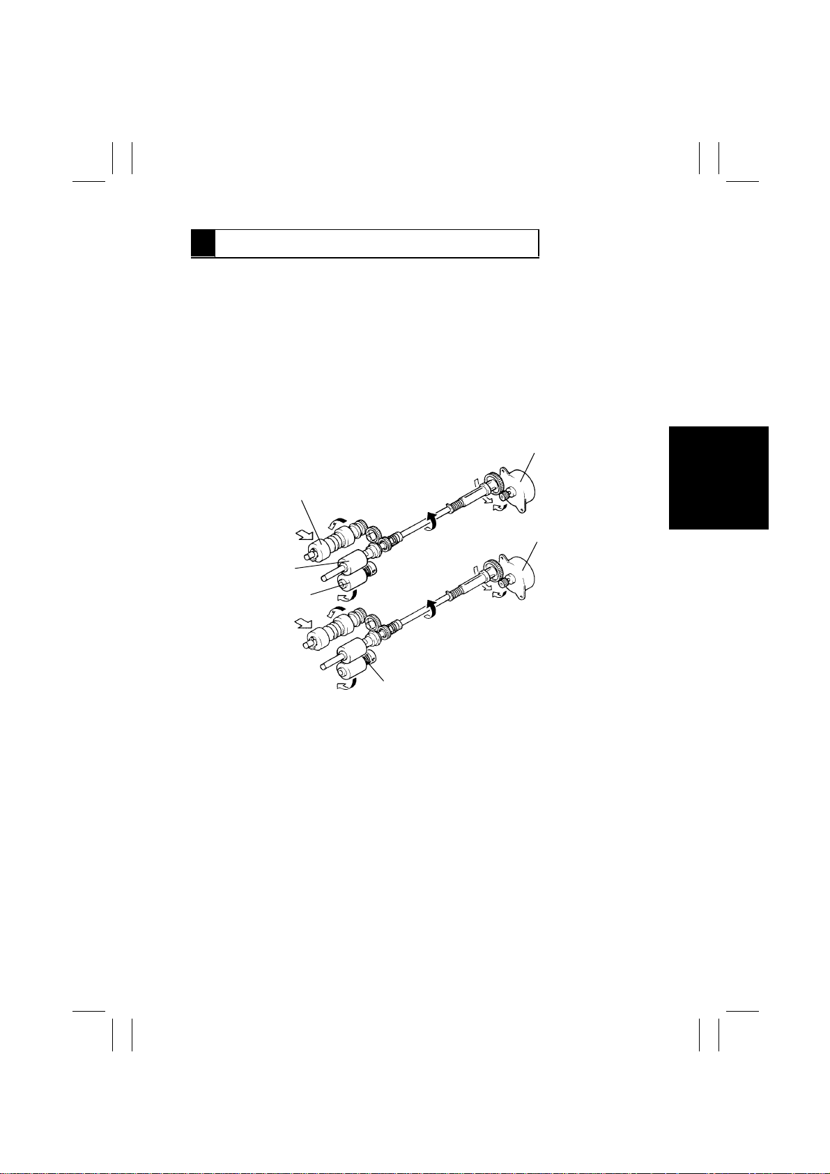
7 PAPER TAKE-UP/FEEDING SECTION
7-1. Paper Take-Up Mechanism
(1) Paper Take-Up Mechanism
•
The paper take-up and feeding mechanism takes up paper from a drawer and feeds it to
the Vertical Transport Roller.
•
The take-up mechanism is driven by 3rd and 4th Drawer Paper Take-Up Motors.
•
Each paper take-up mechanism consists of a T ak e-Up Roll, Feed Roll and Separator Roll
with torque limiter.
•
The Separator Roll is controlled by the torque limiter so that it wil l not transport more than
one sheet of paper at a time.
•
The wider Take-Up Roll assures straight paper transport.
3rd Drawer Paper Take-Up Motor M22
Take-Up Roll
4th Drawer Paper Take-Up Motor M23
Feed Roll
Separator Roll
Torque Limiter
4425M011AA
M-5
Page 9
FrameMaker Ver.5.5(PC) PF-206 OPTION FOR EP1054/EP1085/EP2030
98.06.08
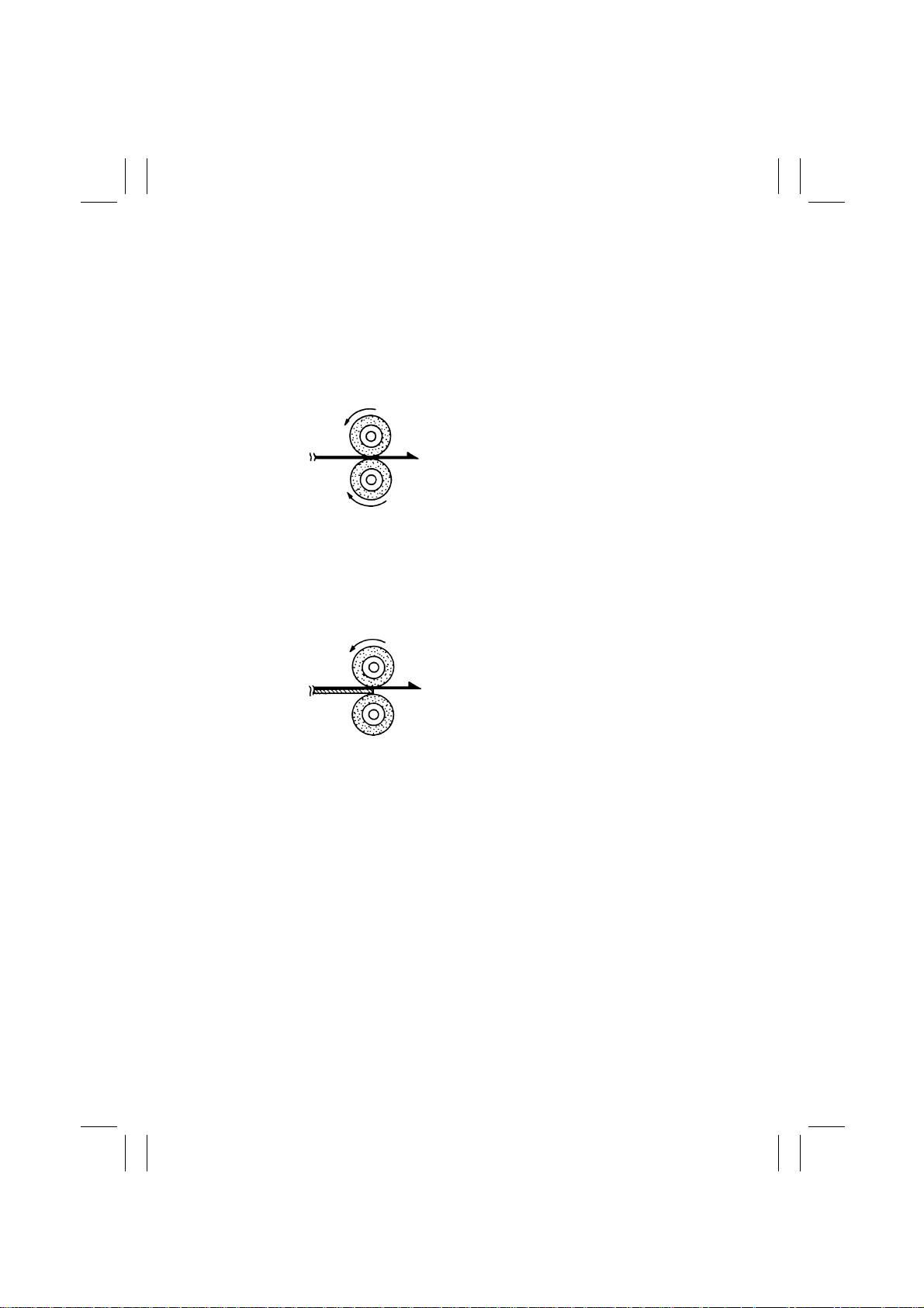
(2) Paper Separating Mechanism
•
The paper separating mechanism ensures that only the top sheet of paper is fed in by
separating the second sheet of paper from the top one.
•
This is accomplished by the difference in friction coefficient between the Feed and Separator Rolls.
<Normal Feeding>
•
When only one sheet of paper is fed, the
friction coefficient on the top side of the
paper is equal to that on the underside.
Driven by the Feed Roll, the paper drives
Feed Roll
the Separator Roll. This causes the paper
to be sent to the Vertical Transport Section.
•
Paper
The friction coefficient varies for different
ambient conditions and types of paper
Separator Roll
4425M012AA
being used, which often causes the Separator Roll to be stationary.
Driven or stationary
<Double Feeding>
•
Since the coefficient of friction between the
top side of the first sheet of paper and the
Feed Roll
Feed Roll is greater than that between the
first and second sheets of paper, the first
1st Sheet of
Paper
sheet of paper is fed into the copier by the
Feed Roll.
Since the friction coefficient between the
2nd Sheet of
Paper
Separator Roll
4425M013AA
Stopped
second sheet of paper and the Separator
Roll is greater than that between the first
and second sheet of paper, the Separator
Roll is not driven and holds the second
sheet of paper.
M-6
Page 10
FrameMaker Ver.5.5(PC) PF-206 OPTION FOR EP1054/EP1085/EP2030
98.06.08
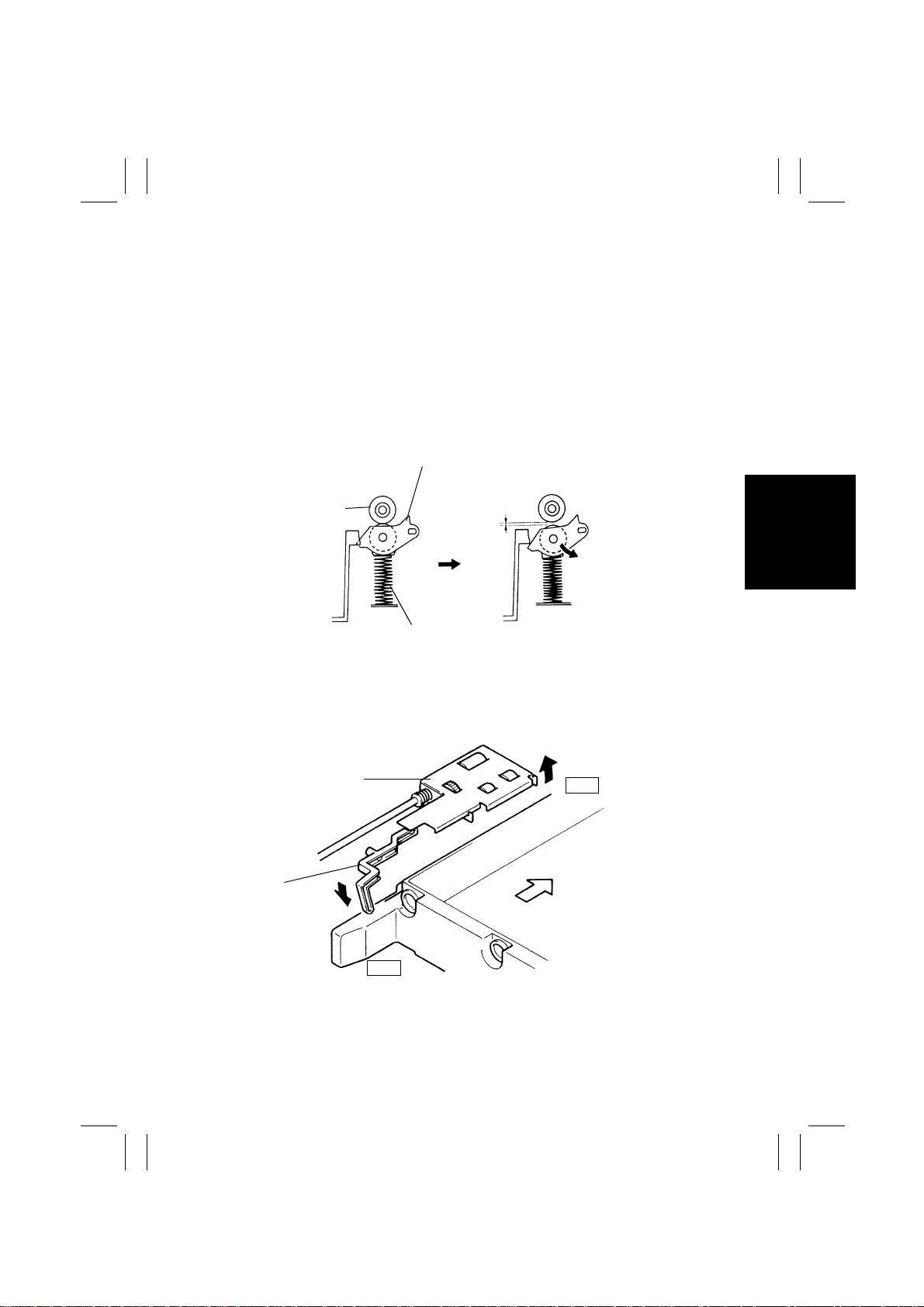
(3) Paper Pressure Releasing Mechanism
•
If the Drawer is pulled out while the paper is between the Feed Roll and the Separator
Roll, the paper is left in the unit. Removal of the paper is difficult.
With this cabinet, opening the drawer automatically disengages the paper and Paper
Take-Up/Feed Roll.
•
The Paper Pressure Releasing Mechanism makes it easier to remove a sheet of paper
held between the Feed Roll and Paper Separator Roll by just opening the drawer.
•
When the Drawer is pulled out, the paper Lifting Plate is lowered and the pressure
release rail pushes down the Separator Roll, disengaging the Feed Roll from the Separator Roll.
<Drawer closed> <Drawer open>
Separator
Roll Assy.
Feed Roll
Drawer
Pressure spring
4444M004AA
(4) Paper Take-Up Roll Retraction Mechanism
•
Pulling the Drawer out causes the Pressure Release Lever to push up the Paper Take-Up
Roll/Feed Roll, freeing the paper from the Paper Take-Up Roll.
Take-Up Roll/Feed
Roll Assy
Front
Pressure
Release Lever
Rear
4425M015AA
M-7
Page 11

FrameMaker Ver.5.5(PC) PF-206 OPTION FOR EP1054/EP1085/EP2030
98.06.08
7-2. Paper Take-Up Control
(1) Paper Take-Up Motor Control
•
The 3rd and 4th Drawer Paper Take-Up Motors which are stepping motor are driven by
the signals from pins 1, 2, 4 and 17 of ICs 7A and 8A on the cabinet’s Master Board
which is controlled by the Master Board of the copier. Each set of these signals is applied
to two windings of the 3rd and 4th Drawer Paper Take-Up Motors, respectively.
4479T52MCB
(2) Paper Take-Up Retry Control
•
If The Paper Take-Up Sensor does not go low because it is not blocked by the paper
within the predetermined time after start of paper take-up, the Drawer paper Take-Up
Motor is started again.
•
A paper misfeed results if a sheet of paper does not reach the Paper Take-Up Sensor
even after three paper take-up sequences.
M-8
4479T53MCB
Page 12

FrameMaker Ver.5.5(PC) PF-206 OPTION FOR EP1054/EP1085/EP2030
98.06.08
(3) Paper Take-Up Interval Contr ol (30 cpm Copier Onl y)
•
The Paper Feed Roll and Separ ator Roll may sometimes fail to separate the subsequent
sheet of paper properly and the leading edge of that paper may be beyond the Feed and
Separator Rolls inside the copier. If the next paper take-up sequence is started in this
condition, the distance between the preceding and the current sheet of paper will
become shorter than normal, resulting in a misfeed.
•
To maintain a given paper take-up interval, therefore, this copier provides the following
control. If it takes the paper more than a specified time to block (L) Paper Take-Up Sensor after Paper Take-Up Motor has been energized, Paper Take-Up Motor is temporarily
deenergized and, an appropriate period of time thereafter, it is energized again (paper
take-up interval control).
(4) Double Feed Paper Take-Up Control (30 cpm Copier Only)
•
Even if the Paper Take-Up Roll takes up two sheets of paper at one time, the double feed
paper take-up control uses the second sheet of paper for the next copy cycle without
causing a paper misfeed. It eliminates a paper misfeed that would otherwise result when
two sheets of paper are taken up at once.
•
If the second sheet of paper is stationary blocking Paper Take-Up Sensor when the trailing edge of the first sheet of paper moves past Vertical Transport Sensor, the copier
determines that it is a double feed condition and provides double feed control.
•
If, howe ver, t he second sheet of paper has reached the V ertical Transport Roller, the double feed control is not provided since the paper is fed further into the copier by the Vertical Transport Roller. This could result in a paper misfeed or the second sheet of paper
being fed through the copier with the first one.
Detecting position of Vertical
Transport Sensor 4 PC22
Vertical Transport Roller 1
Detecting position of 3rd Drawer
Paper Take-Up Sensor PC21
Detecting position of 4th Drawer
Paper Take-Up Sensor PC29
Paper Path
(Leading edge of the paper fed
together with the top one)
Multiple paper feed control
ON
OFF
4444M040AA
M-9
Page 13

FrameMaker Ver.5.5(PC) PF-206 OPTION FOR EP1054/EP1085/EP2030
98.06.08
7-3. Fixed Drawer
•
To convert the paper size of the Fixed Drawer, it is necessary to reposition the Trailing
Edge Stop and Edge Guide. The new paper size should be entered through the control
panel.
Trailing Edge Stop
Paper Lifting Plate
Paper Sizes That Can be Loaded
3rd Drawer 4th Drawer
Metric Areas A5L to A3L 210 × 280L to A3L
Inch Areas 5-1/2” × 8-1/2”L to 11” × 17”L 8-1/2” × 11”L to 11” × 17”
Edge Guide
1174M017AA
7-4. Drawer-in-Position Detection
•
When a Drawer is slid into the Cabinet, Drawer Set Detecting Lever A is pushed in the
direction of the arrow, which blocks the Drawer Set Sensor (goes low).
Rear
Front
A
3rd/4th Drawer
Set Sensor
PC25, 26
1174M018AA
M-10
Page 14

FrameMaker Ver.5.5(PC) PF-206 OPTION FOR EP1054/EP1085/EP2030
98.06.08
7-5. Drawer Paper Lift-Up Mechanism
•
The paper lifting mechanism raises the paper in the Drawer so that the top of the paper
stack is pressed against the Paper Take-Up Roll at a constant pressure.
•
When slid into the Cabinet, the Drawer presses the Drawer Set Lever which engages
Paper Lift-Up Motor Gear 1 with Paper Lifting Arm Gear 2.
•
The Drawer Set Sensor is blocked (goes low) and after a predetermined time, the Drawer
Paper Lift-Up Motor starts turning, causing the Paper Lifting Arm to raise the Paper Lifting Plate.
•
Sliding out a Drawer disengages Gears 1 and 2, lowering the Paper Lifting Plate.
Rear
Paper Lifting Arm
When Drawer is Slid in
3rd/4th Drawer Paper Lift-Up
Sensor (PC19/PC23)
•
The Paper Lifting Arm further raises the
paper after the top sheet of paper is
pressed against the Paper Take-Up Roll.
As the light blocking plate blocks the Paper
Lift-Up Sensor (goes low), the Paper Lift-Up
Motor stops.
Gear 1Gear 2
3rd/4th Drawer
Paper Lift-Up
Motor M24/25
Front
4425M004AA
4425M005AA
4479T54MCB
M-11
Page 15

FrameMaker Ver.5.5(PC) PF-206 OPTION FOR EP1054/EP1085/EP2030
98.06.08
During Copying
•
As sheets of paper are used, the Paper
Take-Up Roll lowers accordingly, unblocking the Drawer Paper Lift-Up Sensor (goes
high).
4425M006AA
•
The Paper Lift-Up Motor starts running,
raising the paper stack until the Drawer
Paper Lift-Up Sensor is blocked (output
goes low).
4425M005AA
•
Energizing and deenergizing of the Paper Lift-Up Motor keeps constant the pressure
between the Paper Take-Up Roll and paper regardless of the height of the paper stack.
M-12
Page 16

FrameMaker Ver.5.5(PC) PF-206 OPTION FOR EP1054/EP1085/EP2030
98.06.08
7-6. Paper Empty Detection
•
A paper empty condition in the 3rd and 4th Drawers is detected by 3rd Drawer Paper
Empty Sensor and 4th Drawer Paper Empty Sensor, respectively, installed in the paper
take-up area of each Drawer.
Paper Lifting Plate
Paper Empty Lever
3rd/4th Drawer Paper Empty Sensor
PC20/PC24
4425M007AA
3rd/4th Drawer Paper Empty
Sensor PC20/24 (blocked)
Paper Present
The paper stack raises the Paper Empty
Lever which bloc ks the Paper Empty Sensor
(goes low).
4425M008AA
(unblocked)
4425M009AA
Paper Not Present
The light blocking plate of the Empty Lever
clears the Paper Empty Sensor which goes
high.
M-13
Page 17

FrameMaker Ver.5.5(PC) PF-206 OPTION FOR EP1054/EP1085/EP2030
98.06.08
7-7. Paper Level Detection (30 cpm Copier Only)
•
The amount of paper still available f or use , or the paper level, of the 3rd/4th Drawer is
detected by 3rd/4th Drawer Paper Lift-Up Motor Pulse Sensor located inside the 3rd/4th
Drawer Paper Lift-Up Motor Assy and pulse disk.
•
The pulse disk is mounted on the shaft of the i ntermediary gear that transmits drive from
the 3rd/4th Drawer Paper Lift-Up Motor. The speed of the pulse disk varies with different
paper levels and the number of pulses detected by the 3rd/4th Drawer Paper Lift-Up
Motor Pulse Sensor is used to determine the paper level.
•
Counting of the number of pulses is started when the 3rd/4th Drawer Paper Lift-Up Motor
is energized and continues until the output from the 3rd/4th Drawer Paper Lift-Up Sensor
goes LOW. The total number of pulses is translated into the amount of paper which is
shown on the Touch Panel as a graphic marker in units of paper ass shown below.
•
As the paper is consumed and each time the Paper Lifting Plate of the drawer is raised
(the 3rd/4th Drawer Paper Lift-Up Motor is energized), the 3rd/4th Drawer Paper Lift-Up
Motor Pulse Sensor detects pulses and that pulse count is accumulated. When the count
reaches the number of sheets of paper in the units shown below, the corresponding segment or segments of the paper level indicator on the Touch Panel go out.
3rd/4th Drawer Paper
Lift-Up Motor M24/25
Pulse Disk
3rd/4th Drawer Paper Lift-Up
Motor Pulse Sensor PC27/28
1134M020AA
Paper Level Indicator
•
1 to 50 sheets
•
50 to 200 sheets
•
200 to 350 sheets
•
350 to 500 sheets
•
500 sheets up
1134M058AA
1134M059AA
1134M060AA
1134M061AA
1134M062AA
M-14
Page 18

FrameMaker Ver.5.5(PC) PF-206 OPTION FOR EP1054/EP1085/EP2030
98.06.08
7-8. Cabinet Paper Dehumidifying Heater (option)
•
To prevent paper passage performance from being degraded by damp paper under
highly humid conditions, the Cabinet Paper Dehumidifying Heater is installed in the bottom of the cabinet.
•
For information on the control of the cabinet paper dehumidifying heater, see “Dehumidifying Switch” in the copier Mechanical/Electrical manual.
M-15
Page 19

FrameMaker Ver.5.5(PC) PF-112 OPTION FOR EP1054/EP1085/EP2030
98.06.08
DIS/REASSEMBLY,
ADJUSTMENT
Page 20

FrameMaker Ver.5.5(PC) PF-206 OPTION FOR EP1054/EP1085/EP2030
98.06.08
1 DISASSEMBLY
1-1. Removal of Exterior Parts
1
1174D003AA
2
11
10
9
4425D001AA
8
6
45
No. Part Name Removal Procedure
1 Lower Right Door After removing Rear Right Cover, remove 2 screws.
2 Rear Right Cover Remove 2 screws.
3 Lower Right Cover After removing Front Right and Rear Right Covers, remove 2
4 Front Right Cover Remove 2 screws.
5 Lower Front Cover After removing Front Left and Right Covers, remove 2 screws.
6 Upper Front Cover After removing Front Left and Front Right Covers, remove 1
7 Front Left Cover Remove 2 screws.
8 Middle Left Cover After removing Front Left and Rear Left Covers, remove 4
9 Lower Left Cover After removing Front Left and Rear Left Covers, remove 2
10 Rear Left Cover Remove 2 screws.
11 Rear Cover Remove 2 screws.
3
screws.
screw.
screws.
screws.
7
D-1
Page 21

FrameMaker Ver.5.5(PC) PF-206 OPTION FOR EP1054/EP1085/EP2030
98.06.08
1-2. Removal of the Guide Plates and Cover Plates
The following procedure applies to each Drawer.
1. Remove the Rear Right Cover and Lower Right
Door.
2. Remove 2 screws. Remove the Paper Guide Plate
and Cover Plate from the Drawer.
4425D003AA
1-3. Removal of Paper Take-Up Roll and Feed Roll Assy from Drawer
1. Slide out the Drawer.
2. Remove the Rear Right Cover and Lower Right
Door.
3. Remove the Paper Guide Plate and Cover Plate
from the Drawer.
4. Remove the springs. Rotate the Separator Roll/
Paper Guide Plate 90° in the direction of the arrow
4425D012AA
and remove the Assy.
4479D001AA
4425D004AA
4425D005AA
5. Remove the screw and Separator Roll Assy
Mounting Plate.
6. Remove 2 C-clips from the Paper Take-Up Roll/
Feed Roll Assy.
7. Remove the left bushing from the Paper Take-Up
Roll/Feed Roll Assy. Remove the right bushing
from the bushing holder.
D-2
Page 22

FrameMaker Ver.5.5(PC) PF-206 OPTION FOR EP1054/EP1085/EP2030
98.06.08
8. While holding down the torsion spring, slide the
Paper Take-Up Roll/Feed Roll Assy to the right
and then remove the Assy.
4425D006AA
NOTE
To reinstall the Paper Take-Up Roll/Feed Roll Assy:
1. Close the drawer
2. Engage the shaft coupling with the pin of the Cabinet
3. Insert the assy. bracket above the Pressure
Release Lever
4425D007AA
4. Hold down the torsion spring and install the assy.
1-4. Disassembly of Paper Take-Up Roll/Feed Roll Assy
1. Remove the Paper Take-Up Roll/Feed Roll Assy.
2. Remove 2 E-rings and a lock pin.
4479D002AA
(1)
NOTE
Keep the lock pin for later use.
(5)
(4)
(3)
(2)
4479D003AA
3. Slide out the Feed Roll shaft, and the following
parts come apart: (1) bushing A, (2) spring, (3)
gear, (4) Feed Roll and, (5) bushing B.
D-3
Page 23

FrameMaker Ver.5.5(PC) PF-206 OPTION FOR EP1054/EP1085/EP2030
98.06.08
4. Remove the E-ring, 2 bushings and then the Paper
Take-Up Roll Assy.
4479D004AA
5. Remove an E-ring, lock pin and then the Paper
Take-Up Roll.
4479D005AA
1-5. Removal of Separator Roll Assy
1. Remove the Paper Guide Plate and Cover Plate.
2. Remove the spring. Rotate the Separator Roll/
Paper Guide Plate 90° in the direction of the arrow
and remove them.
3. Remove the screw and Separator Roll Mounting
Plate.
4479D001AA
4479D006AA
4. Remove the spring and holder from the Separator
Roll Mounting Plate.
5. Remove the Separator Roll Assy from the holder.
D-4
Page 24

FrameMaker Ver.5.5(PC) PF-206 OPTION FOR EP1054/EP1085/EP2030
98.06.08
1-6. Cleaning of Paper Take-Up Roll, Feed Roll and Separator
Roll
1. Slide out the Drawer.
2. Remove the Paper Guide Plate and Cover Plate.
3. Remove the spring. Remove the Separator Roll
and Paper Guide Plate from the Drawer.
4. Remove the screw. Remove the Separator Roll
Assy Mounting Plate.
5. Using a soft cloth dampened with alcohol, wipe
4425D016AA
4444M006AA
clean the Separator Roll.
6. Remove the Paper Take-Up/Feed Roll Assy and,
using a soft cloth dampened with alcohol, wipe
clean the Take-Up Roll and Feed Roll.
1-7. Cleaning of Transport Roller
Using a soft cloth dampened with alcohol, wipe clean
the Transport Roller.
4425D017AA
D-5
Page 25

FrameMaker Ver.5.5(PC) PF-206 OPTION FOR EP1054/EP1085/EP2030
98.06.08
2 ADJUSTMENT
2-1. Adjustment of 3rd and 4th Drawer Reference Position
Requirement
•
Prepare a test chart (A3 size) as shown on the left.
Draw a line on the chart at a point 20 mm from the
right edge.
•
Dimension A on the copy should measure 20±2.0
mm.
1074D089
1. Place the test chart on the Original Glass and align
the rear edge of the test chart with the reference
mark (▲). Lower the Original Cover.
2. Using the 3rd Drawer, make two copies of the test
chart in the full size mode (use A3 paper).
3. Compare the position of the reference line on the
second copy with that on the test chart.
1139D027AA
Tighten the
screws
1139U100A
1139U037AA
4. If the copied line deviates from the reference line,
pull out the 3rd drawer. Loosen 3 screws on the
adjusting plate and then move the plate forward or
backward to adjust the line position.
NOTE
If copied width A<18 mm, move the adjusting plate
toward the rear.
If copied width A>22 mm, move the adjusting plate
toward the front.
5. Loosen the 4 screws shown on the left. Move the
drawer cover in the same direction and the same
distance as the adjusting plate.
6. Repeat steps 1 to 5 for the 4th Drawer.
D-6
Page 26

FrameMaker Ver.5.5(PC) PF-206 OPTION FOR EP1054/EP1085/EP2030
98.06.08
2-2. Adjustment of Vertical Transport Timing Belt
1. Remove the Rear Cover, Front Right Cover, Front
Left Cover, and Upper Front Cover.
2. Remove the Duplex Unit Guide Rail (Right).
3. Go to the rear of the Cabinet and, using a wrench,
loosen the hexagon screw used for adjustment of
the Vertical Transport Belt. Adjust so that the Belt
has no slack.
4425D018AA
4. Check the Belt for tension using a tension gage.
The gage should read 80 to 100 g when the Belt is
pushed to deflect 1 mm.
D-7
Page 27

FrameMaker Ver.5.5(PC) PF-112 OPTION FOR EP1054/EP1085/EP2030
98.06.08
MISFEED
DETECTOIN &
MALFUNCTION
DETECTION
Page 28

FrameMaker Ver.5.5(PC) PF-206 OPTION FOR EP1054/EP1085/EP2030
98.06.08
1 MISFEED DETECTION
1-1. Location of Misfeed Detecting Sensors
Vertical Transport Sensor 4 (PC22)
3rd Drawer Paper Take-Up Sensor (PC21)
4th Drawer Paper Take-Up Sensor (PC29)
4425T201AA
1-2. Misfeed Detection Types and Detection Timings
Any of the following misfeeds occurring in the cabinet is detected under the corresponding
conditions and shown on the copier control panel.
Type Detection
Paper take-up failure
detection
Paper take-up trailing
edge detection
Leading edge
detection by Vertical
Transport Sensor 4
PC22
Trailing edge detection
by Vertical T ransport
Sensor 4 PC22
3rd Drawer Paper Take-Up Sensor PC21 is not blocked (L) after
the lapse of a given period of time after 3rd Drawer paper TakeUp Motor M22 has been energized during the third paper retry
sequence.
4th Drawer Paper Take-Up Sensor PC29 is not blocked (L) after
the lapse of a given period of time after 4th Drawer Paper TakeUp Motor M23 has been energized during the third paper retry
sequence.
PC21 is not unblocked (H) after the lapse of a given period of time
(which varies with paper size) after it has been blocked (L).
PC29 is not unblocked (H) after the lapse of a given period of time
(which varies with paper size) after it has been blocked (L).
PC22 is not blocked (L) after the lapse of a given period of time
after PC21 has been blocked (L).
PC22 is not blocked (L) after the lapse of a given period of time
after PC29 has been blocked (L).
PC22 is not unblocked (H) after the lapse of a given period of time
after PC21 has been unblocked (H).
PC22 is not unblocked (H) after the lapse of a given period of time
after PC29 has been unblocked (H).
T-1
Page 29

FrameMaker Ver.5.5(PC) PF-206 OPTION FOR EP1054/EP1085/EP2030
98.06.08
2 MALFUNCTION DETECTION
Code Description Detection Timing
C0900 3rd Drawer Paper
Lift-Up Sensor failure
C0904 3rd Drawer Paper
Lift-Up Motor M24’s
failure to turn
C0950 4th Drawer Paper
Lift-Up Sensor failure
C0954 4th Drawer Paper
Lift-Up Motor M25’s
failure to turn
•
The 3rd Drawer Paper Lift-Up Sensor PC19 is not
blocked (L) a given period of time after the 3rd Drawer
Paper Lift-Up Motor M13 or M24 has been energized.
•
PC19 is not blocked (L) though the 3rd Drawer Paper
Lift-Up Motor Pulse Sensor PC27 detects a given number of pulses after M24 has been energized.
•
The 3rd Drawer Paper Lift-Up Motor Pulse Sensor
PC27 detects no pulses a given period of time after
M24 has been energized.
•
The 4th Drawer Paper Lift-Up Sensor PC23 is not
blocked (L)
Paper Lift-Up Motor M25 has been energized.
•
PC23 is not blocked (L) though the 4th Drawer Paper
Lift-Up Motor Pulse Sensor PC28 detected a given
number of pulses after M25 has been energized.
•
The 4th Drawer Paper Lift-Up Motor Pulse Sensor
PC28 detects no pulses a given period of time after
M25 has been energized.
a given period of time
after the 4th Drawer
T-2
Page 30

3568724
A
B
C
D
91
A
B
C
D
E
F
G
H
I
DWG.NO.
TITLE
MODEL
VOLTAGE
EFFECTIVE
MACHINE NO.
DATE ISSUED
4479-C002-0A
WIRING DIAGRAM
PF-206
From the copier
XX0201 AND ONWARD
Dec.1998
E
F
G
H
I
12345678
9
Page 31

3568724
A
B
C
D
91
A
B
C
D
E
F
G
H
I
DWG.NO.
TITLE
MODEL
VOLTAGE
EFFECTIVE
MACHINE NO.
DATE ISSUED
4479-C202-0A
CIRCUIT DIAGRAM PWB-A
PF-206
From the copier
XX0201 AND ONWARD
Dec.1998
E
F
G
H
I
12345678
9
 Loading...