

Page 1

EPlO52
DE/REASSEMBLY,
ADJUSTMENT
MINOLTA
Page 2
1158SBDOOOSA
+
For the Utmost safety
l
For replacement parts, use the genuine parts with their part numbers specified in the parts manual. Use
of a wrong part could cause an overload or dielectric breakdown, resulting in an electric shock or fire.
l
Replace a blown fuse or thermal fuse with the corresponding genuine part with its part number specified
in the parts manual. Use of a fuse with a different rating or one with the same rating but of a different
type can result in a fire.
Especially when a thermal fuse blows frequently, the thermal control system
Be sure to take necessary action.
l
Before attempting to disassemble the machine, be sure to unplug its power cord. The machine contains
a high voltage unit and a circuit with a large current capacity that may cause an electric shock or burn
from sparking.
The machine also contains quick moving parts, which could injure a person.
If the machine uses a laser, a person can lose his/her eyesight by a laser beam leak.
l
Wherever feasible, keep the covers and parts mounted when energizing the machine.
If it is absolutely necessary to energize the machine with its cover removed, do not touch an exposed
part that is being charged and use care not to allow your clothing to be caught by a timing belt, gear,
or other moving part.
l
Do not leave the machine unattended while it is being energized.
+
!
Warning
A
i$
probably faulty.
! Caution
A
l
To actuate an interlock switch with
ating jig. Use of folded paper can damage the interlock switch mechanism.
a
cover
removed or opened, be sure to use the interlock switch actu-
Page 3
! Caution
A
l
A high voltage is being applied to the part marked with the symbol shown
on the right. Touching it can cause an electric shock, Be sure to unplug the
power cord when servicing this part or other parts near it.
l
When the machine is energized with any of its covers removed, never use a flammable spray near it,
as a fire can result.
l
Make sure that correct screws (diameter and length of the screw, binding/tapping screws) are used in
the correct places when assembling parts. If a wrong screw is used, a short insulating distance could
result. It could also result in collapsed threads, which provides only a poor grounding connection, resulting in an electric shock.
l
A toothed washer and spring washer, if used originally, must be reinstalled. If they are left out, a contact
failure results, causing an electric shock or fire.
l
Replace a lithium cell only with one having the part number specified in the parts manual. An explosion
could result if the cell is installed with wrong polarity or a wrong cell is installed.
Dispose of a used lithium cell according to the applicable local regulations. Never throw it away or abandon it on the users premises.
+
Other Precautions
l
While the machine is being energized, do not unplug or plug in a connector on a PWB or relay harness.
l
Since the Magnet Roller of the Imaging Unit generates a strong
floppy disk, or magnetic card near it.
l
Use of an air gun
parts to break down. Be sure therefore to use a blower brush or cloth to clean these parts. If a unit is to
be cleaned, be sure to remove the sensors in advance.
l
MQS ICs
tions given in l-2. INSTRUCTIONS FOR HANDLING THE
l
The PC Drum is highly delicate. When handling the PC Drum, follow the precautions given in 1-3. HANDLING OF THE PC DRUM.
l
To reassemble, reverse the order of disassembly unless otherwise specified.
l
Note that replacement of a PWB may call for readjustments or resetting of particular items.
or vacuum
are susceptible to static electricity. When handling a PWB loaded with MOS
+
magnetic
force,
do not bring a CRT, watch,
generates static electricity which can cause the ATDC Sensor and associated
ICs,
follow precau-
PWBs
WITH MQS
ICs.
CAUTION: DANGER OF EXPLOSION IF BATTERY IS INCORRECTLY REPLACED. REPLACE
ONLY WITH THE SAME OR EQUIVALENT TYPE RECOMMENDED BY THE MANUFACTURER.
DISPOSE OF USED BATTERIES ACCORDING TO THE MANUFACTURERS INSTRUCTIONS.
-
Eksplosionsfare ved fejlagtig handtering. Udskiftning ma kun ske med
batteri
af
samme
fabrikat og type. Lever det brugle bafferi tilbage til leverandoren.
ii
Page 4
CONTENTS
1 SERVICE INSTRUCTIONS
l-l. PRECAUTIONS FOR DISASSEMBLY/ADJUSTMENTS
1-2. INSTRUCTIONS FOR HANDLING THE
WITH
MOSICs
.........................................
1-3. HANDLING OF THE PC DRUM
1-4.
PARTS WHICH MUST NOT BE TOUCHED
PWBs
..........................
................
2 1 DISASSEMBLY/REASSEMBLY
2-1.
DOORS, COVERS, AND EXTERIOR PARTS:
IDENTIFICATION AND REMOVAL PROCEDURES
2-2. REMOVAL OF
2-3. BELT INSTALLATIONS
2-4. PAPER TAKE-UP/TRANSPORT SECTIONS
(1)
Removal of the Paper Take-Up Unit
(2) Removal of the Paper Take-Up Rolls
(3) Cleaning of the Paper Take-Up Rolls
(4) Removal of the Suction Unit
(5) Disassembly of the Suction Unit
PWBs
...................................
..................................
...............
.....................
....................
....................
...........................
........................
(6) Disassembly of the Multi Bypass Table (Option)
2-5. OPTICAL SECTION
(1) Removal of the Lens Drive Cable
(2) Winding of the Lens Drive Cable
(3) Removal of the Scanner Drive Cable
(4) Winding of the Scanner Drive Cable
(5) Removal of the Scanner
(6) Cleaning of the Exposure Lamp
(7) Cleaning of the Ist/2nd/3rd Mirrors
(8) Cleaning of the Lens and 4th Mirror
....................................
.......................
.......................
....................
....................
...............................
........................
.....................
.....................
(9) Cleaning of the Optical Section Cooling Fan Filter
2-6. IMAGINGUNIT
.........................................
(1) Disassembly, Cleaning, Replacement and Starter
changing of the Imaging Unit
l
Replacement of the PC Drum
l
Replacement of the Toner Scattering Prevention
Plate
.............................................
l
Replacement of the Cleaning Blade
l
Cleaning of the PC Drum Paper Separator Fingers
l
Cleaning of the Ds Positioning Collars
l
Cleaning of the Paper Dust Remover
...........................
........................
...................
.................
..................
......
.........
..........
........
......
D-l
D-2
D-2
D-4
D-5
D-8
D-10
D-i 1
D-i
1
D-12
D-l 2
D-12
D-i 2
D-13
D-18
D-18
D-19
D-20
D-22
D-24
D-24
D-25
D-25
D-25
D-26
D-26
D-26
D-26
D-27
D-28
D-28
D-28
Page 5
~
l
Replacement of the Toner Antispill Mylar
l
Cleaning of the Upper Pre-Image Transfer
GuidePlate
l
Cleaning of the Magnet Roller Lower Filter
(2) Cleaning of the Main Erase Lamp
(3) Cleaning of the Edge Erase Lamp
CONTENTS
........................................
......................
......................
...............
.............
D-28
D-29
D-29
D-30
D-30
2-7. PC DRUM CHARGE CORONA/IMAGE TRANSFER
CORONA UNIT
(1) Cleaning of the PC Drum Charge Corona Housing
(2) Cleaning of the PC Drum Charge Corona Grid Mesh
(3) Cleaning of the Comb Electrode
........................................
........................
........
......
D-32
D-32
D-32
D-33
(4) Cleaning of the Image Transfer/Paper Separator
Coronas Wires
.......................................
D-33
ei
(5) Cleaning of the Image Transfer/Paper Separator
Coronas Housing
.....................................
D-33
(6) Cleaning of the Lower Pre-Image Transfer Guide
Plate
...............................................
(7) Replacement of the Ozone Filter
2-8. Fusing Unit
............................................
(1) Removal of the Fusing Unit
(2) Cleaning of the Pre-Fusing Guide Plate
(3) Removal of the Upper Fusing Roller
(4) Cleaning of the Upper Fusing Roller
.......................
............................
.................
....................
....................
(5) Cleaning of the Upper Paper Separator Fingers
(6) Cleaning of the Fusing Thermistor
(7) Removal of the Lower Fusing Roller
(8) Cleaning of the Lower Fusing Roller
......................
....................
....................
(9) Cleaning of the Lower Paper Separator Fingers
(10)
Removal of the Oil Roller
(11) Cleaning of the Oil Roller
.............................
.............................
..........
..........
D-34
D-34
D-34
D-34
D-35
D-35
D-37
D-37
D-37
D-38
D-38
D-38
D-39
D-39
3 1 ADJUSTMENT
3-1.
JIGS AND TOOLS USED
................................
3-2. ADJUSTMENT REQUIREMENTS LIST
3-3. ADJUSTMENT OF SWITCHES
(1) Adjustment of Front Door Interlock Switch
3-4. ELECTRICAL/IMAGE ADJUSTMENT
(1) Adjustment of the Maximum Exposure Lamp Voltage
for the Manual Mode
..................................
(2) Adjustment of the Optimum Exposure Setting in the
Manual Mode
........................................
(3) Adjustment of the Optimum Exposure Setting in the
Auto Mode
..........................................
....................
...........................
S21
.....................
...........
D-40
D-41
D-42
D-43
D-44
D-44
D-47
D-48
u
Page 6
CONTENTS
(4) Adjustment of the ATDC Sensor
(5) Adjustment of the Aperture Blades
(6) Adjustment of the Multi Bypass Table Reference
Position..
...........................................
(7) Adjustment of the 1st Drawer Reference Position
(8) Adjustment of the Leading Edge Registration
l
FullSize
l
Enlargement
l
Reduction
..........................................
.......................................
.........................................
(9) Adjustment of the Image Leading Edge Erase
Width
...............................................
(10) Adjustment of the Edge Erase
Lamp Position
3-5. OTHER ADJUSTMENTS
......................................
................................
(1) Adjustment of the Scanner/Mirrors Carriage Position
(2) Adjustment of the Gap Between the Doctor Blade and
Sleeve Roller
........................................
(3) Adjustment of the PC Drum Paper Separator Fingers
Position
1
4 1 MISCELLANEOUS
.............................................
1
4-1. INSTALLATION OF THE PLUG-IN COUNTER MOUNTING
BRACKET (OPTION). . . . . . . . . . . . . . ,
........................
......................
.............
.
m
.
. . . . , , . . , . . , . . . . . D-63
.........
......
D-49
D-50
D-51
D-52
D-53
D-53
Dr55
D-56
D-57
D-59
D-60
D-60
D-61
D-62
Page 7
1139SBDOiOOA
m
SERVICE INSTRUCTIONS
1151SBD0101A
l-1.
PRECAUTIONS FOR DISASSEMBLY/ADJUSTMENTS
1
Observe the following precautions whenever servicing the copier.
l
Be sure to unplug the copier from the outlet before attempting to service the copier.
l
The basic rule is not to operate the copier anytime during disassembly.
If it is absolutely necessary to run the copier with its covers removed, use care not to allow your clothing
to be caught in revolving parts such as the timing belt and gears.
l
Be sure to use the Interlock Switch Actuating Jig whenever it is necessary to actuate the Interlock Switch
with the covers left open or removed.
l
Do not plug in or unplug print jacks on the Board or connect or disconnect the Board connectors while
power is being supplied to the copier.
l
Do not use flammable spray around the copier in operation.
l
The Magnet Roller of the Imaging Unit generates strong magnetic force. Do not bring it near a cathode-ray
tube or watch.
l
The lithium cell in RAM Board PWB-R can burst. At replacement, make sure of the correct polarity and
do not change it or create a closed circuit.
A used lithium cell should be disposed of according to the local regulations and never be discarded casual-
ly or left unattended at the users premises.
l
Do not use an air gun or vacuum cleaner for cleaning the ATDC Sensor and other sensors, as they can
cause electrostatic destruction. Use a blower brush and cloth. If a unit containing these sensors is to be
cleaned, first remove the sensors from the unit.
l
When handling the
l
When handling the PC Drum, observe precautions given in 1-3. Handling of the PC Drum.
l
Note that replacement of a PWB may call for readjustments or resetting of particular items.
l
Use the right screw in the right place at reassembly. Note that some are longer and some are thicker than
PWBs
with MOS
ICs,
observe l-2.
Instructions
for
Handling the
PWBs
with MOS
ICs.
others.
l
A toothed washer is used with the screw that secures the ground wire to ensure positive conduction. Do
not forget to insert this washer at reassembly.
l
To reassemble the copier, reverse the order of disassembly unless otherwise specified.
l
If it becomes necessary to replace the thermal fuse or any other fuse mounted on a board, be sure to use
one of the rating marked on the blown fuse.
Always note the rating marked on the fuse, as the rating and mounting site or number used are subject
to change without notice.
l
Do not pull out the Toner Hopper while the Toner Bottle is turning, as a
damaged
Toner Replenishing Motor
or locking mechanism could result.
If the copier is to be run with the Front Door swung down, make sure that the Toner Hopper is in the locked
position.
CAUTION: DANGER OF EXPLOSION IF BATTERY IS INCORRECTLY REPLACED. REPLACE
ONLY WITH THE SAME OR EQUIVALENT TYPE RECOMMENDED BY THE MANUFACTURER.
DISCARD USED BATTERIES ACCORDING TO THE MANUFACTURERS INSTRUCTIONS.
D-i
Page 8
1139S!3DOiOZA
1-2. INSTRUCTIONS FOR HANDLING THE
PWBs
WITH MOS
ICs
The following precautions must be observed when handling P.W. Boards with MOS (Metal Oxide
Semiconductor)
ICs.
During Transportation/Storage:
l
During transportation or when in storage, new P.W. Boards must not be indiscriminately removed from
their protective conductive bags.
l
Do not store or place P.W. Boards in a location exposed to direct sunlight.
l
When it becomes absolutely necessary to remove a Board from its conductive bag or case, always place
it on its conductive mat in an area as free as possible from static electricity.
l
Do not touch the pins of the
ICs
with your bare hands.
During Replacement:
l
Before unplugging connectors from the
F.W.
Boards, make sure that the power cord has been unplugged
from the outlet.
l
When removing a Board from its conductive bag or conductive case, do not touch the pins of the
ICs
or
the printed pattern. Place it in position by holding only the edges of the Board.
l
Before plugging connectors into the Board, make sure that the power cord has been unplugged from the
power outlet.
During Inspection:
l
Avoid checking the IC directly with a multimeter; use connectors on the Board.
l
Never create a closed circuit across IC pins with a metal tool.
l
When it is absolutely necessary to touch the
ICs
and other electrical components on the Board, be sure
to ground your body.
1151SBD0103A
I-3.
HANDLING OF THE PC DRUM
During Transportation/Storage:
l
Use the specified carton whenever moving or storing the PC Drum.
l
The storage temperature is in the range between -20C and
l
In summer, avoid leaving the PC Drum in a car for a long time.
+40%.
Handling:
l
Ensure that the correct PC Drum is used.
l
Wheneverthe PC Drum has been removed from the copier, store it in its container or protect it with a Drum
Cloth.
l
The PC Drum exhibits greatest light fatigue after being exposed to strong light over an extended period
of time, Never, therefore, expose it to direct sunlight.
l
Use care not to contaminate the surface of the PC Drum with oil-base solvent, fingerprints, and other for-
eign matter.
l
Do not scratch the surface of the PC Drum.
l
Do not apply chemicals to the surface of the PC Drum.
l
Do not attempt to wipe clean the surface of the PC Drum.
D-2
Page 9
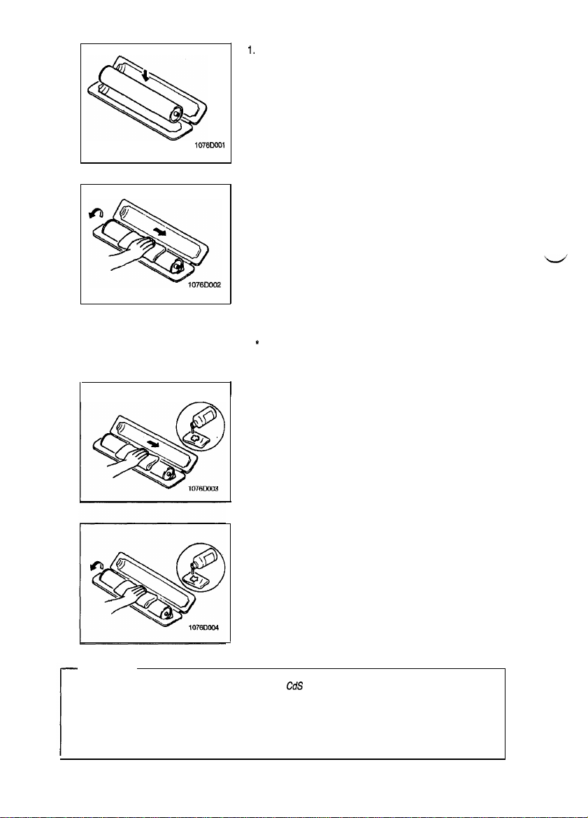
If, however, the surface is contaminated with fingerprints, clean it using the following procedure.
1.
Place the PC Drum into one half of its container.
1076COOl
2.
Gently wipe the residual toner off the surface of the PC
Drum with a dry, Dust-Free Cotton Pad.
a) Rotate the PC Drum so that the area of its surface on
which the line of toner left by the Cleaning Blade is present is facing straight up. Wipe the surface in one continuous movement from the rear edge of the PC Drum to
the front edge and off the surface of the PC Drum.
b) Rotate the PC Drum slightly and wipe the newly ex-
posed surface area with a CLEAN face of the Dust-Free
Cotton Pad. Repeat this procedure until the entire surface of the PC Drum has been thoroughly cleaned.
*
At this time, always use a CLEAN face of the dry Dust-Free
Cotton Pad until no toner is evident on the face of the Pad
after wiping.
1
3. Soak a small amount of either ethyl alcohol or isopropyl alcohol into a clean, unused Dust-Free Cotton Pad which
has been folded over into quarters. Now, wipe the surface
of the PC Drum in one continuous movement from its rear
edge to its front edge and off its surface one to two times.
* Never move the Pad back and forth.
Using the SAME face of the Pad, repeat the procedure explained in the latter half of step 3 until the entire surface of
the PC Drum has been wiped. Always OVERLAP the
areas when wiping. Two complete turns of the PC Drum
would be appropriate for cleaning.
-
NOTES
l
The Organic Photoconductor Drum is softer than
CdS
and Selenium Drums and is therefore suscepti-
ble to scratches.
l
Even when the PC Drum is only locally dirtied, wipe the entire surface.
l
Do not expose the PC Drum to direct sunlight. Clean it as quickly as possible even under interior illu-
mination.
l
If dirt remains after cleaning, repeat the entire procedure from the beginning one more time.
D-3
Page 10
1151SBD0104A
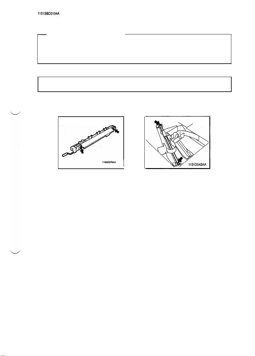
1-4. PARTS WHICH MUST NOT BE TOUCHED
(1) Screws
-
Purpose of Application of Red Paint
Red
paint is applied to the screws which cannot be readjusted, set, or reinstalled in the field.
The basic rule is not to remove or loosen the screws to which red paint is applied. In addition, be advised
that, if two or more screws are designated as those which must not be touched on a single part, only
one representative screw may be marked with red paint.
(2) Variable Resistors on Board
Do not turn the variable resistors on boards for which no adjusting instructions are given in ADJUSTMENT.
(3) Other Screws
Lower Pre-Image Transfer
Guide Plate (2 screws)
Lens Rail height
setting screws (2)
D-4
Page 11
1139SBD0200A
DISASSEMBLY/REASSEMBLY
1158SSD0201A
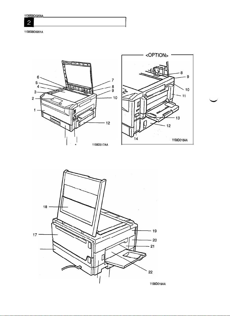
2-1.
DOORS, COVERS, AND EXTERIOR PARTS: IDENTIFICATION AND RE-
1
MOVAL PROCEDURES
<OPTION>
16
15
I'
14
1158D017AA
I
24
1158D018AA
23
1158D019AA
D-5
Page 12
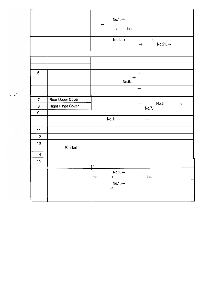
No.
Front Door
1
Control Panel
2
Original Scales
3
4
Oriainal Glass
Rear Upper Cover
5
(Small)
Left Hinge Cover
6
Part Name
Removal Procedure
Swing down
Belt. + Remove two screws that secure the Front: Door (only
on one side). + Slide
screws have been removed.
Swing down
the Upper Half of the copier. + Remove
two screws that secure the control panel and loosen another
five screws that secure the control panel.
Remove two screws that secure the Scales.
Remove the Original Cover. + Release and swing up the
Upper Half of the copier. + Remove the Screw Cover and one
mounting screw of No.5
Remove the Original Cover. + Remove one screw that
secures the Left Hinge Cover.
No.1.
-+
Remove one screw that secures the
Zhe
Door to the side from which the
No.1.
+
Remove No.9. + Release and swing up
No.21.
+
Remove
Remove the Original Cover. + Remove
Upper Right Cover
9
Right Cover
IO
Middle Right Cover
Right Door
Multi Bypass Table
Mounting
Counter Cover
1 st Drawer
Rear Cover Swing down
16
17
Upper Rear Cover
181 Original Cover
Remove the Original Cover by pulling it up.
Bracket
Remove one screw that secures
Remove
secure No.1 0.
Remove four screws that secure No.1 1.
Open No.1 2 and remove it by lifting it up.
Remove two screws that secure the Multi Bypass Table
Mounting Bracket.
Remove No.1 4 by snapping if off.
Slide out the Drawer and remove one screw that secures the
Stopper
Ihe
copier. + Remove two screws
Swing down No-l.
the copier.
Rear Cover.
No.6,
No.7.
No.11,
+
Remove No.9. + Remove two screws that
at the rear left: corner.
No.1.
+
Release and swing up the Upper Half of
-_)
Release and swing up the Upper Half of
-_j
Remove three screws that secure the Upper
that
8 and 9.
secure the Rear Cover.
+
D-6
Page 13
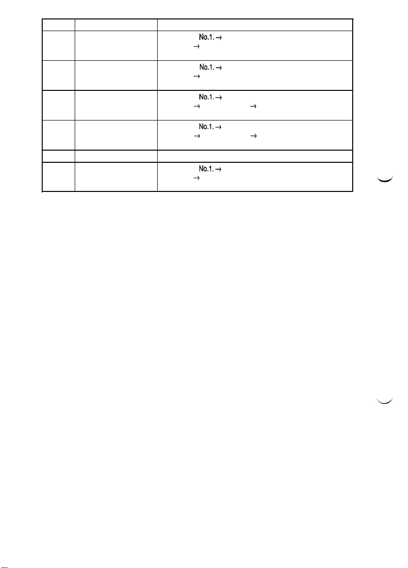
No.
19
20
21
22
2324Lower Left Cover
Part Name
Upper Left Cover
Middle Front Left Cover Swing down
Front Exit Cover
Rear Exit Cover
Middle Rear Left Cover
Removal Procedure
Swing down
the copier.
Cover.
the copier. + Remove one screw that secures the Middle
Front Left Cover.
Swing down
the copier.
cures the Front Exit Cover.
Swing down
the copier. + Remove No.26. + Remove one screw that secures the Rear Exit Cover.
Remove two screws that secure the Lower Left Cover.
Swing down
the copier.
Rear Left Cover.
No.1.
+
Release and swing up the Upper Half of
-_j
Remove four screws that secure the Upper Left
No.1.
+
Release and swing up the Upper Half of
No.1.
+
Release and swing up the Upper Half of
--f
Remove No.22. + Remove one screw that se-
No.1.
+
Release and swing up the Upper Half of
No.1.
+
Release and swing up the Upper Half of
-_)
Remove one screw that secures the Middle
I
D-7
Page 14
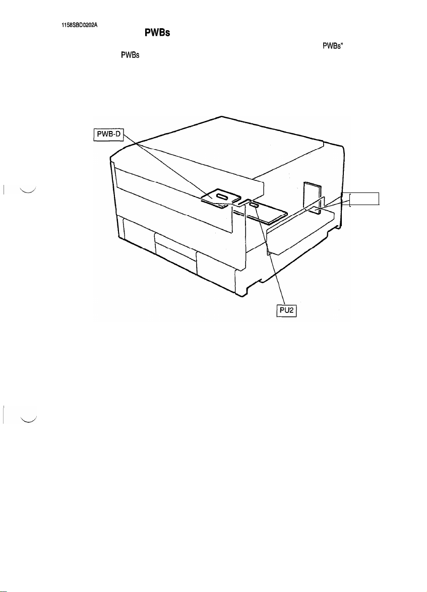
1158SBD0202A
2-2. REMOVAL OF
l
When removing a PWB, first go over PRECAUTIONS FOR HANDLING THE
SWITCHES ON
l
Replacement of a PWB may call for readjustments or resetting of particular items.
l
The removal procedures given on the next page omit the steps to unplug connectors and remove the PWB
PWBs
PWBs
and use the removal procedures given on the next page.
PWBs
contained in
from the PWB support.
PWB-C
D-8
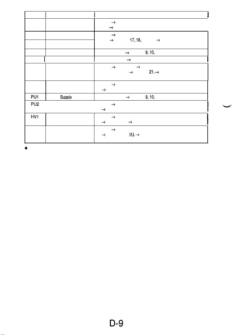
Page 15
Symbol
+
Details of Readjustments/Resetting Involved In Replacement of PWB-R, and UN3.
1
PWB-A Master Board
PWB-C
PWB-D
PWB-E
PWB-H 1 AE Sensor Board
PWB-P Control Panel
PWB-R RAM Board
PUl Power
PU2
HVl High Voltage Unit Open 1. + Release and swing up the Upper Half of the copi-
UN3 ATDC Sensor
l
When PWB-R is replaced:
Carry out Memory Clear and then make the Tech. Rep. Program, Users Choice, and Adjust settings
again.
l
When UN3 is replaced:
Discard the developer which had been used until UN3 was replaced, charge the Developing Unit with
fresh starter, and adjust ATDC.
Name
Open 1. + Release and swing up the Upper Half of the
copier. + Remove 19.
Power Supply Board
Noise Filter Board
Motor Drive Board Open 1 and 12. + Remove 9,10, and 11.
Supplv
Unit Open 1 and 12. + Remove
DC Power Supply Unit
Open 1. + Release and swing up the Upper Half of the
copier. + Remove
that secure the Power Supply Unit Cover.
1
Remove 3 and 4. + Remove the optical cover.
Open 1. + Remove 9. + Release and swing up the Upper
Half of the copier. + Remove
that secure Control Panel.
Open 1. + Release and swing up the Upper Half of the copier. + Remove 19.
Open 1. + Release and swing up the Upper Half of the copier. 4 Remove 17 and 18.
er. + Remove 19. + Remove PWB-A.
Open 1. + Release and swing up the Upper Half of the copi-
er. + Take out the
Synchronizing Roller Guide Unit.
Removal Procedure
17,18,
and 19. + Remove four screws
21.
+
Remove seven screws
9,10,
and 11.
I/U. +
Remove two screws that secure the
I
I
I
I
D-9
Page 16
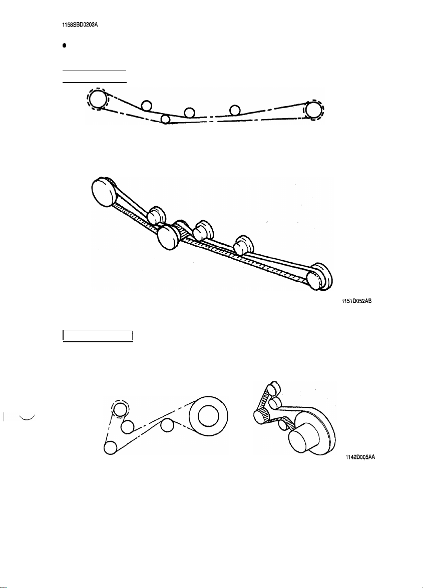
1158SBD0203A
2-3. BELT INSTALLATIONS
0
Rear View
Drive/Suction Unit
115lD052AB
1
Paper Take-Up Unit
1
1142DOq5AA
D-10
Page 17
ll58SBD0204A
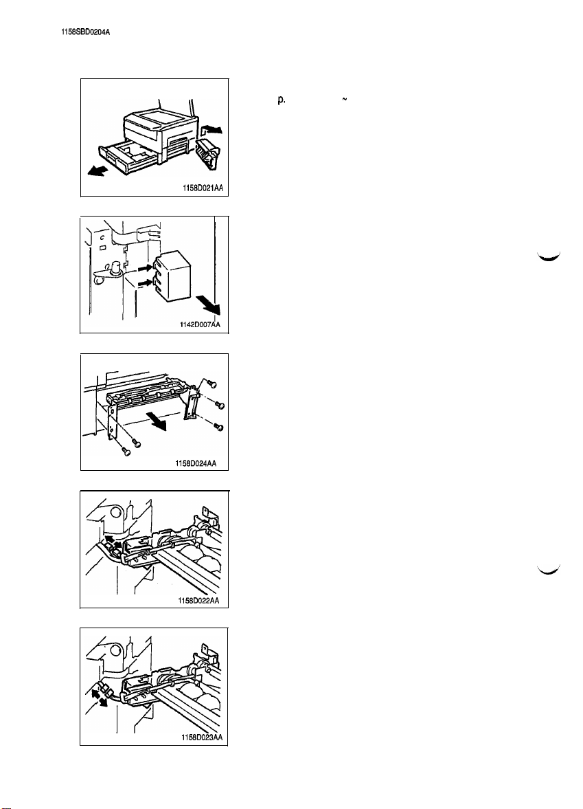
2-4. PAPER TAKE-UP/TRANSPORT SECTIONS
(1) Removal of the Paper Take-Up Unit
1.
Remove the Multi Bypass Table. (OPTION)
See p. D-13. (NO 1 m 7)
2.
Slide out the 1 st Drawer.
1158D021AA
3.
Press the tabs at the two places indicated by the arrow
and, at the same time, remove the cover.
4.
Remove five screws and the Paper Take-Up Unit.
1158D024AA
1158D022AA
1158D023AA
5.
Unplug the one connector from the solenoids on the Paper
Take-Up Unit.
6.
Remove the Rear and Rear Upper covers.
7.
Remove the DC Power Supply Unit.
6.
Remove the harness from the wiring saddle.
9.
Unplug the one connector.
D-11
Page 18
(2) Removal of the Paper Take-Up Rolls
Remove one screw to remove the Paper Take-Up Roll.
1.
(3)
Cleaning of the Paper Take-Up Rolls
Remove the Paper Take-Up Unit from the copier.
1.
Using a soft cloth dampened with alcohol, wipe clean the
2.
Paper Take-Up Rolls.
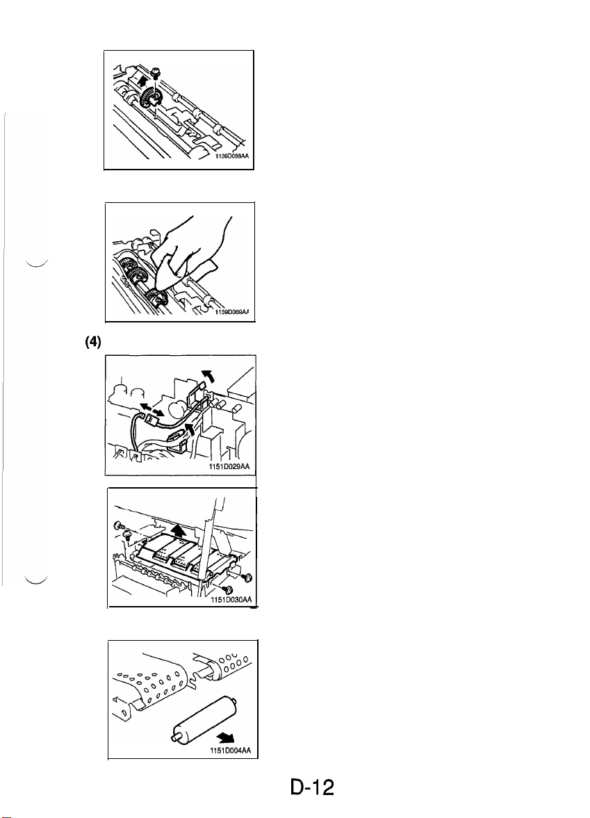
Removal of the Suction Unit
(4
Remove the Fusing
1.
2.
Unplug the Suction
from the clamp.
Unit. (See p. D-34.)
Fan connector and remove the wire
3.
Remove four screws to remove the Suction Unit.
1151D030AA
(5) Disassembly of the Suction Unit
Remove the four Suction Drive Rolls and six bushings by
1.
pulling them in the direction of the arrow.
1151D004AA
D-i 2
Page 19
1139D094AA
1151
DOOGAA
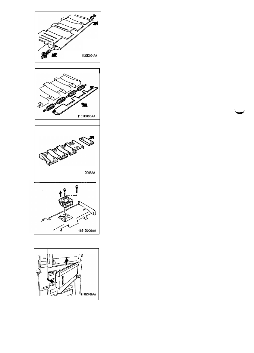
2.
Snap off the three E-rings from the Suction Drive Unit.
3. Remove the gear and bushings.
1
4. Remove the Pre-Fusing Guide Plate.
5. Remove the Suction Drive Unit.
6.
Remove the four belts.
7. Remove the Suction Fan.
(6) Disassembly of the Multi Bypass Table (OPTION)
1. Remove the Right Door.
D-l 3
Page 20
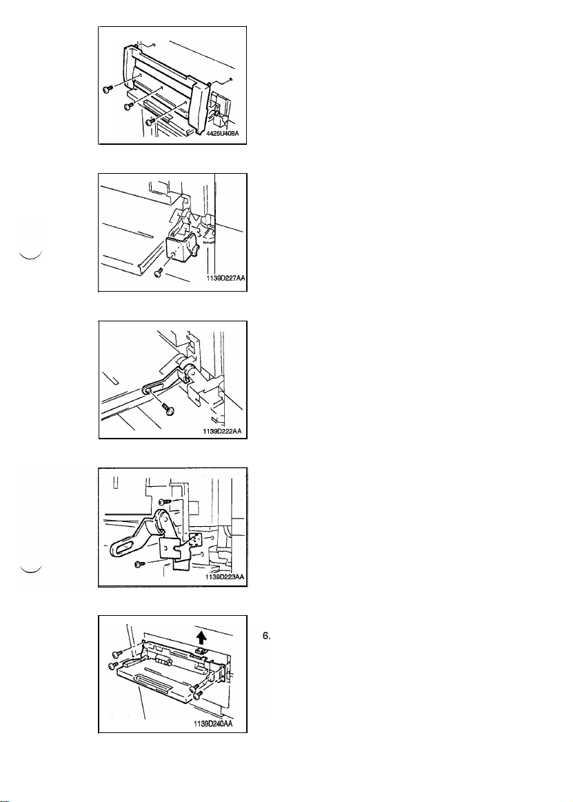
2.
Remove three screws and the Large Cover.
d
A
3.
Remove one screw and the Small Cover.
4.
Remove three screws and the Guide Lever Unit.
113QD240AA
5.
Remove four screws and the Multi Bypass Table.
Unplug the Multi Bypass Table connector.
D-14
Page 21
1139DlOlAA
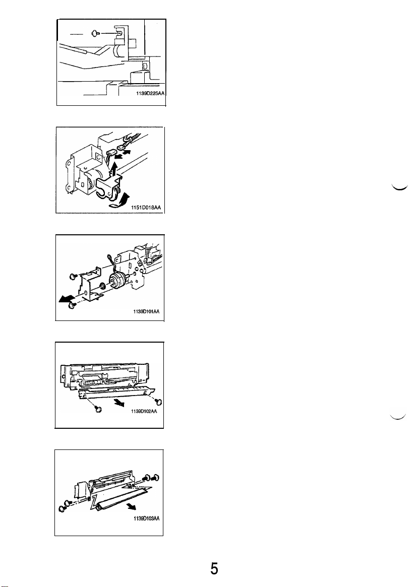
7.
Remove one screw and the Multi Bypass Table.
8.
Unplug one connector.
9.
Remove the Tension Unit.
10.
Remove two screws and the Clutch Mounting Bracket.
113QDlOZAA
113QD103AA
11.
Remove two screws and the Lower Guide.
12.
Remove four screws and the Separator Guide Plate Unit.
D-i
5
Page 22

1139D105AA
the parts shown on the left up against the copier frame
13.
Remove two screws and the Lever.
I
1139D106AA
,133D103AA
14.
Snap off one C-clip and remove the Separator Unit.
NOTE
l
Please use tweezers when reinstalling the C-clip.
r
15.
Snap off one C-clip and remove the Separator Roll Assy.
16.
Remove three screws and the Solenoid Mounting Bracket.
D-l 6
Page 23

113QDl10AA
1139DlllAA
Unplug one solenoid connector.
Unplug one photosensor connector and remove the harness from the clamp.
sure that the Solenoid is in the deenergizedposition.
19. Snap off the two C-clips to remove the Paper Take-Up Roll
Unit.
1139DllZAA
20.
Snap off the three C-clips to remove the Paper Feed Roll.
21.
Snap off one C-clip and remove the Paper Take-Up Roll.
D-l 7
Page 24

1151SBDO205A
2-5. OPTICAL SECTION
(1) Removal of the Lens Drive Cable
1.
Remove two screws and the Optical Section Cover.
2.
Remove three screws and the Lens Cover.
1
3.
Remove two screws, two clamps and the Lens Motor Unit.
4.
Remove one screw and the Cable Fixing Bracket.
5.
Remove the spring.
6.
Remove the Cable Drive Gear and the Lens Drive Cable.
D-i 8
Page 25

I
(2) Winding of the Lens Drive Cable
1.
Hold the Cable Drive Gear in position with its Bead at the
bottom.
1139D119AA
2.
Wind the shorter length of the Cable three turns clockwise
around the Cable Drive Gear, working from the back to the
front side. Then tape it.
I
1139D12OAA
3.
Wind the longer length of the Cable five turns counterclockwise around the Cable Drive Gear, working from the
front to back side. Then tape it.
1139D121AA
4.
Slide the Cable Drive Gear onto its shaft and insert a
wrench into the hole to position the Cable Drive Gear.
Pass the longer length of the Cable through the U-shaped
5.
hole in the Light Blocking Plate and wind it around the
Pulley farther away from the Cable Drive Gear.
D-i
9
Page 26

Temporarily secure the longer length of the Cable to the
Cable Fixing Bracket, ensuring a distance of 5 f 2 mm for
the dimension shown on the left.
Wind the shorter length of the Cable around the Pulley
which is nearer to the Cable Drive Gear.
Hook the spring onto the shorter length of the Cable and
8.
pull it to hook onto the longer length of the Cable.
9.
Check that the dimension noted in step 6 above measures
5 f 2 mm. Then, secure the Cable Fixing Bracket.
Remove the wrench and peel off the two pieces of tape.
10.
(3) Removal of the Scanner Drive Cable
l
Remove the Original Cover, Original Scales, and Original Glass.
l
Remove the Middle Right, Upper Right, Right, Upper Left, and Upper Rear Covers.
l
Remove the Left and Right Hinge Covers, Rear Upper Cover (Small), and Rear Upper Cover.
1. Align the Scanner with the rectangular hole in the upper
copier frame and remove the screw from the Scanner Fix-
ing Bracket.
2. Remove the Fixing Bracket.
3. Unhook the spring to remove the shorter length of the
Cable.
D-20
Page 27

4.
Move the
2ncV3rd
Mirrors Carriage toward the Scanner
Drive Gear so that the Cable slacks off and then remove
the longer length of the Cable.
5.
Remove four screws and PWB-A.
Remove three screws and the Scanner Motor Mounting
6.
Bracket.
7.
Snap off one E-ring and remove the Scanner Drive Gear.
Remove two screws and the Pulley.
Remove the Cable.
1139Dl32AA
1
D-21
Page 28

(4) Winding of the Scanner Drive Cable
+
Remark
Wheneverthe Scanner Drive Cable has been rewound,
Mirrors Carriage Position. See p. D-60.
be sure
to make
theAdjustment
of the Scanner/
Pulley C
\ 1139D134AA
1139D135M
11390133AA
1.
Fit the Pulley to the Scanner Drive Gear using two screws.
2. Wind the shorter length of the Cable 2 turns clockwise
1
around the Pulley, working from the back to front side.
3. Wind the longer length of the Cable
clockwise
around the Pulley, working from the
side. Then, slip the Cable Holding Jig onto the Pulley.
5-3/4
turns
front
counter-
to back
D-22
Page 29

4.5.Fit the Scanner Drive Gear onto the Scanner Motor Mount-
ing Bracket using one E-ring.
Secure the Scanner Motor Mounting Bracket to the frame
using three screws.
6.
Insert a wrench into the holes in the Scanner Drive Gear
.
1151D033AA
and the frame to position the Gear.
Wind the longer length of the Cable around Pulleys C and
7.
B and then secure it to the frame.
113OD13OAA
1139D234AA
1139D141AA
Wind the longer length of the Cable around the lower
groove in Pulley B (of the two grooves). Position the
nal
of the Cable as illustrated on the left.
8.
Wind the shorter length of the Cable around Pulleys A and
termr-
B.
r
NOTE
Wind the shorter length of the Cable around the upper
groove in Pulley B (two grooves).
D-23
I
Page 30

I
c
9.
Fit the Cable into the groove in the Wire Guide and hook
the spring.
Remove the wrench and Cable Holding Jig.
(5) Removal of the Scanner
4
Turn the Scanner Drive Gear to move the Scanner to the
right-hand side of the copier. Then, remove three screws
I
and the Scanner.
(6) Cleaning of the Exposure Lamp
1.
Remove two screws and the Exposure Lamp Terminal.
2. Slide out the Exposure Lamp.
1076D131
3.
Using a soft cloth dampened with alcohol, clean the Lamp
by wiping its surface gently in one direction.
r
NOTE
When reinstalling the Lamp, use care not to allow the protruding navel of the Lamp to hit against the Lamp Reflector
and that the protruding nave/points toward the opening in
the Lamp Reflector.
D-24
Page 31

I
(7) Cleaning of the
Ist/2nd/3rd
Mirrors
1.
Turn the Scanner Drive Gear to move the Scanner away
from the Mirrors. Then, wipe clean the 1
with a soft cloth.
st/2nd/3rd
Mirrors
(8) Cleaning of the Lens and 4th Mirror
I.
Gently dust off the surface of the Lens and 4th Mirror by
using a dry soft cloth.
ror is seriously contaminated.
(9) Cleaning of the Optical Section Cooling Fan Filter
1.
Unhook the Fan Cover at the bottom by slightly raising
and, at the same time pulling, the two catches on the bottom.
1139D149AA
2.
Clean the Filter with a brush or a vacuum cleaner.
D-25
Page 32

1151SBD0206A
2-6. Imaging Unit
(1) Disassembly, Cleaning, Replacement and Starter Changing of the Imag-
ing Unit
1.
Remove the Imaging Unit from the copier.
2.
Remove two screws and the Imaging Unit Cover.
3.
Remove one screw and the PC Drum Charge Corona Unit.
Replacement of the PC Drum
4.
Remove two screws and one Drum Pin to remove the PC
Drum.
in the Manual and Auto Mode. See pp. D-47 to D-48.
Replacement of the Toner Scattering Prevention Plate
Remove one screw, one shoulder screw and the Toner
Scattering Prevention Plate.
Tilt the Developing Unit to remove the developer.
D-26
Page 33

I
Replacement of the Cleaning Blade
7.
Remove two screws and the Lid.
8. Remove the spring.
9.
Remove two screws, one spring, one cap and the Cleaning
Blade. Replace it with a new one.
-
NOTE
When the Cleaning Blade has been replaced, apply toner
to
the entire surface of the new Cleaning Blade.
Applying Toner to Cleaning Blade
Apply toner to the entire surface of the Cleaning Blade. (Do not forget to coat the surfaces on both ends.)
1
1
Install the PC Drum.
I
J
Apply a thin coat of toner to the PC Drum.
1
I
(
Turn the PC Drum
l/2
turns backward, then turn it one complete turn forward.
D-27
Page 34

I
Cleaning of the PC Drum Paper Separator Fingers
10.
Using a soft cloth dampened with alcohol, wipe clean the
Paper Separator Fingers.
Cleaning of the Ds Positioning Collar
Cleaning of the Paper Dust Remover
S
11.
Using a soft cloth dampened with alcohol, wipe clean the
Ds Positioning Collars.
12.
Remove two screws, two compression coil springs and the
Synchronizing Roller Unit.
When removing the Synchronizing Roller Unit, use care
not to lose the compression coil springs. At reinstallation,
fit the close-coiled end of the springs to the bosses on the
13. Remove the Synchronizing Roller.
14.
Using a brush, whisk the dust and dirt off the Filter.
1139D153AA
Replacement of the Toner Antispill Mylar
15.
Remove two screws and the Bias Seal.
(No Bias Seals are mounted in the copiers for the U.S.A.,
Canada, and Europe.)
16.
Remove two screws and the Toner Antispill Mylar and replace the Mylar.
D-28
Page 35

against the Imaging Unit Housing and the front side of the
copier (in the directions of the arrows).
Cleaning of the Upper
p
Cleaning of the Magnet Roller Lower Filter
We-Image
1139D160AA
Transfer Guide Plate
17. Remove two screws and the Upper Pre-Image Transfer
18.
19.
Guide Plate.
Using a brush, whisk toner and dust off thesurface of the
Upper Pre-Image Transfer Guide Plate.
Using a brush, whisk toner and dust off the Magnet Roller
Lower Filter.
(No Magnet Roller Lower Filters are mounted in the copiers for the U.S.A., Canada, and Europe.)
113QDWlAA
Refit the parts to the Imaging Unit and reinstall the Imaging
20.
Unit in the copier.
Charge fresh starter and make the ATDC adjustment. See
21.
p. D-49.
D-29
Page 36

(2) Cleaning of the Main Erase Lamp
1.
Remove four screws and PWB-A.
2.
Remove three screws and
3.
Unplug the connector of the Main Erase Lamp.
4.
Remove the Imaging Unit,
5.
Pull out the Toner Bottle Holder to the front.
6.
Remove one screw and the Main Erase Lamp.
Using a brush or a soft cloth dampened with alcohol, clean
the Erase Lamp.
-
NOTE
Do not touch the Lamp with bare hands.
HVl
.
(3) Cleaning of the Edge Erase Lamp
)
1.
Remove four screws and PWB-A.
1151
D034AA
2.
Insert PWB-A into the copier to secure it.
1151D035AA 1
D-30
Page 37

3.
Go to the rear of the copier and unplug the connector of
Edge Erase Lamp.
4. Remove the imaging Unit.
5.
Remove one screw and the Edge Erase Lamp.
-
NOTE
When removing the Erase Lamp, use care not to lose the
pressure spring in the rear.
6.
Using a brush or a soft cloth dampened with alcohol, clean
the Erase Lamp.
ment of the Edge Erase Lamp Position. See p. D-59.
D-31
Page 38

1158SBD0207A
2-7. PC DRUM CHARGE CORONA/IMAGE TRANSFER CORONA UNIT
(1) Cleaning of the PC Drum Charge Corona Housing
1. Remove the Imaging Unit.
2.
Remove one screw and PC Drum charge Corona Unit.
3.
Press the Mesh Holder on the front of the Corona Unit in
the direction of arrow A to remove the Grid Mesh.
1151
D037AA
4.
+
1139D175AA
Remove the Cleaning Pad Cover.
5.
Remove the End Caps from the front and rear ends of the
Unit.
Use care not to deform the Electrode. When removing it,
f@ff;ffyj+
1139D176AA
7.
Using a soft cloth dampened with alcohol, wipe the Housing clean of dirt.
(2) Cleaning of the PC Drum Charge Corona Grid Mesh
1.
Blow all foreign matter off the Grid with a blower brush.
n
a
sot?
cloth dampened with alcohol to clean serious
1139D178AA
D-32
con-
Page 39

(3)
Cleanqng
of the Comb Electrode
1.
Clean the Comb Electrode using the Corona Unit Cleaning
Lever.
1139D179AA
(4) Cleaning of the Image Transfer/Paper Separator Coronas Wires
Clean the Image Transfer Corona Wire using the Corona
Wire Cleaning Lever.
1139DZOAA
Remove the four Paper Guides.
Dampen a soft cloth with alcohol, hold it with a pair of tweezers, and wipe the Paper Separator Corona Wire gently in
one direction.
(Go from the hook to spring end.)
(5) Cleaning of the Image Transfer/Paper Separator Coronas Housing
1,
Remove the four Paper Guides.
2. Remove the two End Caps.
3.
Remove the Image Transfer and Paper Separator Corona
Wires.
-
NOTE
I -
When removing the Wire, unhook the spring end first
1139D181AA
113QDlQZAA
and use care to prevent break and deformation. (Use a
pair of tweezers)
Keep the Corona, Wire Cleaning Lever (for the image
Transfer Corona) pressed all the way back in. Do not
attempt to remove the Lower Pre-Image Transfer Guide
Plate as it has been adjusted for correct height.
4.
Using a soft cloth dampened with alcohol, wipe the Housing clean of dirt.
D-33
Page 40

(6) Cleaning of the Lower Pre-Image Transfer Guide Plate
1.
Using a brush, whisk dust off the Lower Pre-Image Transfer Guide Plate.
I
113QDliiAA
(7) Replacement of the Ozone Filter
1. Press the Filter Cover Bracket in the direction of the arrows
and pull it off.
2. Remove the Filter and replace it with a new one.
1158SBD0208A
2-8. Fusing Unit
(1) Removal of the Fusing Unit
Remove one screw and the Ground Wire of the Fusing
Unit.
1151D038AA
2. Unplug the Fusing Heater Lamp connector and remove
the wires from the clamp.
1151DOO8AA
3.
Unplug the Fusing Thermistor connector and remove the
wires from the two clamps.
D-34
Page 41

Remove one screw and the Fusing Unit Locking Plate.
Turning it in the direction of the arrow, remove the Fusing
Unit.
-
NOTE
I
When reinstalling the Fusing Unit, install the Locking Plate
as illustrated on the left.
I
1139D246AA
I
(2) Cleaning of the Pre-Fusing Guide Plate
1.
Using a soft cloth dampened with alcohol, wipe clean the
Guide Plate.
(3) Removal of the Upper Fuslng Roller
1.
Remove two screws and the Fusing Unit Front Cover.
2.
Remove two screws and the Fusing Unit Upper Cover.
1139DlQlAA
3.
Remove two screws and the Upper Paper Separator Fingers Unit.
1139DlQZAA
D-35
Page 42

1151D012AA
4.
Remove four Cord Holders of the Fusing Thermistor.
5.
Remove one screw and the Fusing Thermistor.
6.
Remove the screw and clamp that secure the Lamp harness at the front of the copier.
7.
Remove the rear lamp harness and harness clamp (six).
8.
Remove the mounting bracket (one screw).
1151D013AA
1151D014AA
9.
Remove the Fusing Thermoswitch (two screws).
D-36
Page 43

p
1139DlOfMA
10. Slide out the Fusing Heater Lamp.
11. Remove two C-clips.
12. Remove one spur gear.
13. Remove two bushings.
14. Remove the Upper Fusing Roller.
1139D197AA
(4) Cleaning of the Upper Fusing Roller
1.
Using a soft cloth dampened with alcohol or silicone
wipe clean the Upper Fusing Roller.
oil,
/
/
w
(5)
Cleaning of the Upper Paper Separator Fingers
J,
1130D198AA
1. Using a soft cloth dampened with alcohol or silicone oil,
wipe clean the Upper Separator Fingers.
(6) Cleaning of the Fusing Thermistor
1.
Remove one screw to remove the Fusing Thermistor.
2. Using a soft cloth dampened with alcohol or silicone oil,
wipe clean the Thermistor,
1151D039AA
D-37
Page 44

Removal of the Lower Fusing Roller
113OD20iAA
_
1.
Turning it in the direction of the arrow, remove the Lower
Separator Fingers Unit.
2. Remove the Lower Fusing Roller
(8) Cleaning of the Lower Fusing Roller
1.
e
Using a soft cloth dampened with alcohol or silicone oil,
wipe clean the Lower Fusing Roller.
1139D203AA 1
(9) Cleaning of the Lower Paper Separator Fingers
1.
Using a soft cloth dampened with alcohol or silicone oil,
wipe clean the Lower Separator Fingers.
1139D204AA
I
D-38
Page 45

I
(10) Removal of the Oil Roller
1.
Remove the front holder (one screw).
2. Remove the front bushing.
(11) Cleaning of the Oil Roller
1. Using a brush, clean the Oil Roller.
1136D232AA
D-39
Page 46

1139SBD0300A
ADJUSTMENT
1151SBD0301A
3-1. JIGS AND TOOLS USED
+
Important
l
When adjusting the positions of the Scanner and Mirrors Carriage, use Jigs numbered
l
When adjusting the gap between the Doctor Blade and Sleeve Roller, use Jigs numbered
l
When adjusting the position of PC Drum Paper Separator Fingers, use Jigs numbered
0
0
Cable Holding jig
Front Door Interlock
Switch Actuating Jig
0
and
0
0
and 6.
@.
and
63.
1139D071AA
0
Scanner Positioning jig
0
Sleeve/Magnet Roller
Position jig
\\@
1139D075AA
0
PC Drum Paper
Separator Fingers
Positioning jig
lTYr!Ll
G9
Scanner/Mirrors
Carriage Positioning jig
8
D.B. Adjusting jigs
1139D072AA
1151
D022AA
D-40
Page 47

1158SBD0302A
3-2. ADJUSTMENT REQUIREMENTS LIST
Adjustment Item
Max. Exposure Lamp
Voltage
Optimum Exposure Setting
in the Manual Exposure
Mode
Optimum Exposure Setting
in the Auto Exposure Mode
Multi Bypass Table
Reference Position
1 st Drawer Reference
Position
Full Size Leading Edge
Registration
~~~r$sa~$
Reduction Leading Edge
Registration
Image Leading Edge Erase
Width
Edge Erase Lamp Position
Leading Edge
Requirements Adjusting Point
100 to 127V areas: 81 f 1 V
200
to 240V areas: 162 4 2 V Contra pane
Kodak Gray Scale:
no image of the 1 st step,
faint image of the 2nd step
(100 %) 20 k 2 mm
(100%)20+2mm
(100 %) 20 5 1.5 mm Control panel
(200 %) 40 13 mm Control panel
(50%)
10*1.5mm
0.5 to 6.5 mm
1 + 0.5 mm
Control panel
Control panel
Multi Bypass Table
Drawer Front Panel
Control panel
Control panel
Adjusting Screw for
Edge Erase Lamp position
Ref.
Page
D-44
D-47
D-48
D-51
D-52
D-53
D-55
D-56
D-57
D-59
D-41
Page 48

1151SSD0303A
~
3-3. ADJUSTMENT OF SWITCHES
Microswitches
The following microswitches are used in various parts of this copier.
Wirina for the NO Tvoe
NC (Normally-Closed)
:
Current flows between NC and COM when the actuator is open.
Wiring for the NC Type
NO (Normally-Open): Current flows between NO and COM when the actuator is closed.
COM (Common): Common contact for NC and NO
Requirement
Actuator
The gap between the switch and actuator
0.5 mm when the
actuator is closed.
should be 0.1 mm to
g*
0.5 mm
1074Do40
I
Out-of-Adjustment
0
If the gap between the switch and actuator is too big, current does not at times flow to NC or NO.
l
If there is no gap between the switch and actuator, the actuator is bent or the switch can be broken.
(When the actuator is closed)
I
D-42
Page 49

(1) Adjustment of Front Door Interlock Switch S21
1,
Open the Right Door.
2,
Remove the Middle Right Cover. (4 screws)
Remove the Upper Right Cover. (2 screws)
Remove the Right Cover. (2 screws)
5.
Swing down the Front Door.
6.
Remove the
7.
Remove the Interlock Switch Cover. (2 screws)
I/U
Lock Lever. (1 screw)
113BD239AA
6.
Loosen the two screws that secure Front Door Interlock
Switch
521.
Move
S21
as far toward the front side of the
copier as it will go and temporarily secure it in position.
9.
Gently swing the Front Door closed and then tighten the
two S21 mounting screws to specification.
l
The Switch is wired for the NO type.
D-43
Page 50

1158SBD0304A
~
3-4. ELECTRICAL/IMAGE ADJUSTMENTS
(1) Adjustment of the Maximum Exposure Lamp Voltage for the Manual
Mode
+
Requirement
l
Maximum Exposure Lamp voltage: 81 & 1 V (RMS value)
+
Important
l
After the maximum Exposure Lamp voltage has been adjusted, be sure to make the following adjustments: Optimum Exposure Setting in the
Mode.
Manual Mode and Optimum Exposure Setting in the Auto
1.
Remove the Large Cover. (3 screws)
2.
Insert the probes of the multimeter into the receptacles of
the Exposure Lamp voltage measurement connector.
On the control panel, press the Stop Key, Multi-Copy Key
0,
Stop Key, and Multi-Copy Key 1, in that order, to set
the copier into a state ready to enter a particular
Mode.
Press Multi-Copy Key 1 and then 3 to set the copier into
the F3 Test Mode. (At this time, the Magnification Ratio Indicator shows the currently set value and the Multi-Copy
Display shown
F3.)
Tech. Rep.
Press the Full Size Key to select the Lamp voltage setting
mode. (The Magnification Ratio Indicator shows L + current setting.)
Press the Start Key to light up the Exposure Lamp and, using the Zoom Up/Down Keys, adjust to obtain the Lamp
voltage of 81 V.
Press the Stop Key to stop the F3 operation. (Or, the operation will be automatically completed in about 30 sec.)
Press the Panel Reset Key twice (or turn OFF the Power
Switch) to return the copier back into the normal mode.
-
NOTE
For the Root Mean Square values and Mean values, see
p. 48-50. Most testers, voltmeters, or multimeters used in
the field show only the mean values.
D-44
Page 51

When using the testers, voltmeters, or multimeters which show only the mean value, not Rms values, carry
out the following procedure.
1.
Measure the line voltage.
2.
Referring to the Mean Value Chart corresponding to each voltage area, see the figure under the volt-
age obtained in step
If the line voltage is 125 V and Rms value is 81 V, for example, the mean value is 54.5 V.
Therefore, it is recommended that the voltage be adjusted so that the mean value is set as close to 54.5
V as possible.
MEAN VALUE
CHART FOR 115/l
104 105 106 107 106 109
81
.O
60.7 60.3 60.0
20/l
27V AREAS
1.
110
111
112 113
59.7 59.2 59.0 58.5 58.2 58.0
57.7
v;;“;
114 115 116
81
.O
57.3 57.0 56.8 56.5 56.2 56.0
124 125 126 127 126 129 130
81.0 54.7 54.5 54.3 54.2 54.0 53.7 53.5 53.2 53.0 52.8
134 135 136 137 138 139 140
81 .O
52.7 52.5 52.2
117
116 119
52.1
52.0 51.7 51.5
120
121
122 123
55.7 55.5 55.2
131
132 133

MEANVALUE
CHARTFOR200/220/240VAREAS
180
181
182 183 184 185 186 187 188 189
162.0 135.9 135.2 134.5 133.8 133.2 132.6 131.9 131.4 130.8 130.2
190
191
192 193 194 195 196 197 198 199
162.0 129.7
162.0 124.7 124.2 123.9 123.5
162.0 120.7 120.4 120.0 119.7 119.2 119.0 118.6 118.2 118.0 117.6
162.0 117.2 117.0 116.7 116.4
162.0 114.2 114.0 113.7 113.5 113.2 112.9 112.7 112.4
162.0
129.1
200
201
210
211
220
221
230
231
240
241
111.6 111.4
128.6
128.1
127.6
127.1
126.6
126.1
125.7 125.2
202 203 204 205 206
123.1
122.7 122.2 121.9 121.5
212 213 214 215 216 217 218 219
222 223 224 225 226 227 228 229
116.1
115.7 115.5 115.2 114.9 114.6
232 233 234 235 238
242 243 244 245 246 247 248 249
111.1
110.9 110.6 110.4 110.2 109.9 109.7 109.5
207
237
208 209
121.1
238 239
112.1
111.9
!$$$E
y;,/E
!$/$
YfffE
vMA'L"u"E
y;,/E
MEAN
,,AL,,E
I
w
250
162.0 109.2
260
162.0
162.0
107.1
270
105.1
251
252 253 254 255 256 257 258 259
111.4
111.1
110.9 110.6 110.4 110.2 109.9 109.7 109.5
261
262 263 264 265 266 267 268 269
106.9 106.6 106.4 106.2 106.0 105.7 105.6 105.4 105.2
271
272 273 274
104.9 104.7 104.5 104.2
v;;fE
D-46
VMAELfuNE
y;$E
Page 53

(2) Adjustment of the Optimum Exposure Setting Cn the Manual Mode
+
Requirement
l
When the manual exposure setting is at the central indication, no image of step no. 1 of a Kodak Gray
Scale should be produced on the copy, but a faint image of step no. 2 should be produced.
+
Important
l
This adjustment should be carried out only after completing Adjustment of the Maximum Exposure
Lamp Voltage for the Manual Mode and Adjustment of the Aperture Blades.
Place the Kodak Gray Scale lengthwise, face down, and
at the center on the Original Glass. Place a sheet of pure
white A3 or 11
inal Cover.
Set the copier into the Manual Exposure Mode. Set the Exposure Setting to the central or
copies to be made by using the Multi-Copy Keys. (Use A3
paper.)
Press the Start Key.
Check that the 15th copy meets the requirement given
above.
n
x 17"
paper over it and then lower the Orig-
fifth
indication and enter
15
4.
If the exposure is out of adjustment, press the Stop Key,
Multi-Copy Key
that order, to set the copier into a state ready to enter a
0,
Stop Key, and Multi-Copy Key
1,
in
par-
tiaular Tech. Rep. Mode.
Press Multi-Copy Key 1 m and then
5,
the F3 Test
fvlode.
(At this time, the Magnification Ratio In-
3
to set the copier into
dicator shows the currently set value and the Multi-Copy
Display shows
6.
Using the Zoom Up/Down Keys, vary the value on the
F3.)
Magnification Ratio Indicator as necessary.
After the adjustment has been made, press the Panel Re-
7.
set Key twice (or turn OFF the Power Switch) to return the
copier back into the normal mode.
Increase the value to make the image lighter
Decrease the value to make the image darker.
D-47
Page 54

(3) Adjustment of the Optimum Exposure Setting in the Auto Mode
+
Important
l
This adjustment must be made after the optimum exposure setting in the Manual Mode has been ad-
justed.
1.
Place about five sheets of A3 or 11 x
Original Glass and lower the Original Cover.
On the control panel, press the Stop Key, Multi-Copy Key
0,
Stop Key, and Multi-Copy Key 1, in that order, to set
thecopier intoastate ready to
Mode.
Press Multi-Copy Keys 1 and
F5
Test Mode. (At this time, the Multi-Copy Display shows
F5.)
4.
Press the Start Key to let the copier make the adjustment.
5.
After the adjustment has been made, press the Panel Reset Key twice (or turn OFF the Power Switch) to return the
copier back into the normal mode.
enteraparticularTech.
17
paper on the
Rep.
5
to set the copier into the
-
NOTE
Pressing the Start Key lets the copier make the adjustment of optimum exposure setting.
During the adjustment, the Start Key is lit up orange. It turns to green as soon as the adjustment is completed. (It takes about 5 sec. to make the adjustment.) The Full Size Key can be used to alternately display on the Magnification Ratio Indicator either the
voltage value (AE Sensor output).
aojusting
value (AE Sensor memory level) or the
D-48
Page 55

(4) Adjustment of the ATDC Sensor
+
Important
l
This adjustment is not necessary when a new Imaging Unit has been installed. (The ATDC Sensor is
automatically adjusted when the starter is charged and the Power Switch turn ON.)
l
The adjustment must be made whenever the currently used Imaging Unit has been charged with new
starter.
1.
Load the starter.
On the control panel, press the Stop Key, Multi-Copy Key
0,
Stop Key, and Multi-Copy Key 1, in that order, to set
the copier into a state ready to enter a particular Tech. Rep.
Mode.
Press Multi-Copy Keys 1 and 8 to set the copier into the
F8 Test Mode. (At this time, the Multi-Copy Display shows
F8.)
4.
Press the Start Key to let the copier make the ATDC Sensor adjustment automatically. (It takes about 5 min. for the
copier to complete the adjustment procedure.)
5.
After the adjustment has been made, press the Panel Reset Key twice (or turn OFF the Power Switch) to return the
copier back into the normal mode.
The
I/U
Counter available from the Consumables counter menu is automatically reset when the ATDC
Sensor
gain adjustment has been completed.
The Full Size key can be used to alternately display the data on the Magnification Ratio Indicator, either
the ATDC Sensor output voltage or ATDC Sensor gain.
D-49
Page 56

I
(5) Adjustment of the Aperture Blades
+
Requirement
l
There should be no dark or light bands running in the feeding direction on copies produced. (Adjust to
obtain the mean image density for all areas.)
+
Important
l
If dark and light bands running in the feeding direction occur on copies, make this adjustment after
checking the following.
1) The Drum Charge Corona Wire, Grid Mesh, and Image Transfer Corona Wire are free of dirt.
2) The surfaces of the Mirrors and Lens are free of dirt.
3) The surfaces of the Exposure Lamp and Main Erase Lamp are free of scratches and dirt.
4) The Cleaning Blade is free of waviness.
Make a copy under the following control panel settings.
Original
Paper
Magnification : 100 %
ratio
Exposure
2.
Remove the Original Glass.
3.
Turn the copy on the Copy Tray around as shown to reverse the leading and trailing edges and align it with the
Aperture Blades.
:
A3 or A4 crosswise,
11”
x
17”
or 11” x
8-i/2”
crosswise
:
A3 or A4 crosswise,
11” x 17” or 11” x
:
Manual (setting convenient for check)
8-l/2”
crosswise
4.
Adjust to obtain the mean image density for all areas of the
copy.
-
NOTE
To make the image darker, move the Aperture Blade toward the Auxiliary Reflector,
To make the image lighter, move the Aperture Blade away
from the Auxiliary Reflector.
D-50
Page 57

(6) Adjustment of the Multi Bypass Table Reference Position
+
Requirement
l
Ready a test chart (A3 or 11 )r x 17) as shown on the left.
Draw a line on the chart at a point 20 mm from the right
edge as shown.
l
Dimension A on the copy should measure
20 f 2.0 mm.
a
I
II
cl
M+
t
A
1074DO89
I
I
r
t
1139D026AA
Place the test chart face down on the Original Glass and
align its rear left corner with the
Width Scale on the left side of the platen.
Then, lower the Original Cover.
Using the Multi Bypass Table, make two full size copies.
Using the second copy, compare the position of the refer-
ence line on the copy with that on the test chart.
If the line does not meet the requirement, loosen the two
screws (OPTION : three screws) that secure the Multi By-
pass Table and move the Table as necessary in the direc-
tion of the arrows.
NOTE
If dimension A on the copy is smaller than 18 mm, move
the
Table to the front If it is more than 22 mm, move the
Table to the rear.
When an Automatic or Duplexing Document Feeder is
mounted, it involves changing the Original Glass. This in
turn results in the position of the Original Length Scale being slightly shifted toward the rear. This is corrected by
installing the Original Positioning Plate.
bmarker
on the Original
<OPTION>
1151D024AA
D-51
Page 58

(7) Adjustment of the 1st Drawer Reference Position
+
Requirement
l
Ready a test chart (A3 or 11 x 17) as shown on the left.
Draw a line on the chart at a point 20 mm from the right
edge as shown.
l
Dimension A on the copy should measure 20 k 2.0 mm.
+
Important
l
If the Paper Tray of the Drawer needs to be moved for adjustment, make sure that it is moved straight,
not slantwise (as skewed feeding of paper could result).
Place the test chart face down on the Original Glass and
align its rear left corner with the Dmarker on the Original
Width Scale on the left side of the platen.
Then, lower the Original Cover.
Using the 1 st Drawer, make two full size copies.
(Use A3 or
Using the second copy, compare the position of the reference line on the copy with that on the test chart.
If the line does not meet the requirement, slide out the 1 st
Drawer, loosen the four screws shown on the left, and
move the Paper Tray as necessary to the front or rear.
If
dimension A on the copy is smaller than 18 mm, move
the Paper Tray to the rear. If it is more than 22 mm, move
the Paper Tray to the front.
r
NOTE
11
x 17 paper.)
D-52
Page 59

(8) Adjustment of the Leading Edge Registration
Full Size
+
Requirement
l
Ready a test chart (A3 or 11
Draw a line across the test chart at a point 20 mm from
the leading edge and use it as the reference line.
Dimension A at the center on the copy should meet the
x 17)
as shown on the left.
Reduction (50
0
Setting value range: 30 to 70
a
Movement equivalent to 1 step of setting value: 0.28 mm
+
Important
l
After having set the copier into the Adjust Mode, make two single copies and use the second copy for
the check. (The first copy represents the data before adjustment.)
l
When full size leading edge registration has been adjusted, it affects leading edge registration in the
enlargement and reduction mode. Be sure, therefore, to check for registration in these modes, too.
Place the test chart face down on the Original Glass and
align its rear left corner with the D marker on the Original
Width Scale on the left side of the platen. Then, lower the
Original Cover.
Make two single copies in full size mode (100 %) and
check for leading edge registration on the second copy.
(If it meets the requirement, go to Adjustment of Enlargement Leading Edge Registration.)
%)
lO.O?
I
1.5
I
D-53
Page 60

3.
If the registration does not meet the requirement, go to the
control panel and press the Stop Key, Multi-Copy Key
Stop Key, and Multi-Copy Key 1, in that order, to set the
copier into a state ready to enter a particular Tech. Rep.
Mode.
Press the Stop Key and then press the Start Key to set the
4.
copier into the Adjust Mode. (At this time, the Magnification
Ratio Indicator shows A.)
5.
Press Multi-Copy Key
the Magnification Ratio Indicator shows
Copy Display, the current setting value.)
Press the Clear Key to clear the current setting value.
6.
With the old setting value used as reference, enter the new
7.
setting value using the appropriate Multi-Copy Keys.
NOTE
If
dimension A on the copy is smaller than 18.5 mm,
decrease the setting value.
If dimension A on the copy is greater than 2
increase the setting value.
4
and press the Start Key. (Then,
A4
and the
1.5
0,
Multi-
mm,
Press the Start Key to validate the setting.
8.
9.
Press the Panel Reset Key twice (or turn OFF the Power
Switch) to return the copier back to the normal mode.
10.
Make two single copies and check for leading edge registration on the second copy. (If it does not meet the requirement, perform steps 3 through 10 again.)
D-54
Page 61

I
Enlargement
(H-i-71
mEI
AUTO
1139D032CA
Afterthe
1.
2.
3.
4.
leading edge registration in the
been adjusted, make two single copies in an enlargement
mode (200 %) and check for leading edge registration on
the second copy.
(If the enlargement leading edge registration meets the requirement, go to Adjustment of Reduction Leading Edge
Registration.)
If the registration does not meet the requirement, go to the
control panel and press the Stop Key, Multi-Copy Key
Stop Key, and Multi-Copy Key
copier into a state ready to enter a particular Tech. Rep.
Mode.
Press the Stop Key and then press the Start Key to set the
copier into the Adjust Mode. (At this time, the Magnification
Ratio Indicator shows A.)
Press Multi-Copy Key
the Magnification Ratio Indicator shows A 5 and the Multi-Copy Display, the current setting value.)
5
and press the Start Key. (Then,
full
size mode has
1,
in that order, to set the
0,
Press the Clear Key to clear the current setting value.
5.
With the old setting value used as reference, enter the new
setting value using the appropriate Multi-Copy Keys.
7.
Press the Start Key to validate the new setting.
Press the Panel Reset Key twice (or turn OFF the Power
a.
Switch) to return the copier back to the normal mode.
Make two single copies and check for leading edge regis-
9.
tration on the second copy. (If it does not meet the requirement, perform steps 2 through 9 again.)
D-55
Page 62

Reduction
After the leading edge registration in an enlargement
mode has been adjusted, make two single copies in a reduction mode (50 %) and check for leading edge registration on the second copy.
If the registration does not meet the requirement, go to the
control panel and press the Stop Key, Multi-Copy Key
Stop Key, and Multi-Copy Key l, in that order, to set the
copier into a state ready to enter a particular Tech. Rep.
Mode.
Press the Stop Key and then press the Start Key to set the
copier into the Adjust Mode.
Ration Indicator shows A.)
(Atthis
time, the Magnification
0.
Press Multi-Copy Key
4.
the Magnification Ratio Indicator shows A5 and the
Copy Display, the current setting value.)
Press the Clear Key to clear the current setting value.
5.
6.
With the old setting value used as reference, enter the new
setting value using the appropriate Multi-Copy Keys.
If dimension A on the copy is greater than 11.5 mm, increase the setting value.
7.
Press the Start Key to validate the new setting.
8.
Press the Panel Reset Key twice (or turn OFF the Power
Switch) to return the copier back to the normal mode.
9.
Make two single copies and check for leading edge regis-
tration on the second copy. (If it does not meet the require-
ment, perform step 2 through 9 again.)
5
and press the Start Key. (Then,
Multi-
D-56
Page 63

(9) Adjustment of the Image Leading Edge Erase Width
+
Requirement
l
Ready a test chart (A3 or 11 17) as shown on the left.
Paint a 20 mm-long rectangle in black at the center of the
test chart along its leading edge as shown. Adjust so that
the erase width along the leading edge of the painted
area measures 0.5 to 6.5 mm.
n
I
l
Setting value range: 42 to 58
l
Movement equivalent to 1 step of setting value: 0.75 mm
l
Having a greater setting value results in a greater erase width.
l
Having a smaller setting value results in a smaller erase width.
+
Important
l
This adjustment must be made after the leading edge registration adjustment has been completed.
1074D107
Place the test chart face down on the Original Glass and
align its rear left corner with the ()marker on the Original
Width Scale on the left side of the platen.
Then, lower the Original Cover.
Make two single copies in full size mode (100 %) and
check for leading edge erase width on the second copy.
If the erase width does not meet the requirement, go to the
control panel and press the Stop Key, Multi-Copy Key
Stop Key, and Multi-Copy Key
copier into a state ready to enter a particular Tech. Rep.
Mode.
Press the Stop Key and then press the Start Key to set the
copier into the Adjust Mode. (At this time, the Magnification
Ratio Indicator shows A.)
1,
in that order, to set the
0,
Press Multi-Copy Key 1 l 2
5.
(Then, the Magnification Ratio Indicator shows A 12 and
the Multi-Copy Display, the current setting value.)
and press the Start Key.
D-57
Page 64

1
6. Press the Clear Key to clear the current setting value.
7.
With the old setting value used as reference, enter the new
setting value using the appropriate Multi-Copy Keys.
If the erase width on the copy is less than 0.5 mm,
Press the Start Key to validate the setting.
8.
Press the Panel Reset Key twice (or turn OFF the Power
9.
Switch) to return the copier back to the normal mode.
Make two single copies and check for leading edge erase
10.
width on the second copy. (If it does not meet the requirement, perform steps 3 through 9 again.)
-
11580006CA
D-58
Page 65

(10) Adjustment of the Edge Erase Lamp Position
+
Requirement
l
Edge erase width: Within 1 4 0.5 mm
+
Important
l
This adjustment must be made after the reference positions of the Multi Bypass Table and 1 st Drawers
have been adjusted.
With the Original Cover raised, place a sheet of A4 or
8-l/2 x 11 paper lengthwise on the Original Glass.
With the Original Cover raised, make a full size copy.
Check the erase width on the
erase width adjusting screw as necessary to obtain an
erase width of less than 1 + 0.5 mm.
-
NOTE
Loosening the screw will make the erase width smaller.
Tightening the screw will make the erase width greater.
front
edge and turn the edge
D-59
Page 66

1158SBD0305A
3-5. OTHER ADJUSTMENTS
(1) Adjustment of the Scanner/Mirrors Carriage Position
+
Requirement
l
With the Scanner positioned correctly with reference to the upper copier frame, there should be no gap
between the Scanner/Mirrors Carriage and the Scanner/Mirrors Carriage Positioning Jig.
1.
Remove the Original Cover, Original Scales, and Original
Glass.
2.
Temporarily tighten the screw on the Scanner Drive Cable
Holding Bracket.
/
1139D051AA
1139D241AA
3.
Align the rectangular hole in the upper copier frame with
the U-groove in the Scanner, then insert the Scanner Positioning Jig into the hole.
Install the Scanner/Mirrors Carriage Positioning Jig between the Scanner and Mirrors Carriage.
Loosen the screw that has been temporarily tightened in
step 2. Turn the helical gear of the Scan Pulley to press the
Mirrors Carriage up against the Scanner/Mirrors Carriage
Positioning Jig and the Scanner.
Tighten the screw on the Scanner Drive Cable Holding
Bracket
D-60
Page 67

(2) Adjustment of the Gap Between the Doctor Blade and Sleeve Roller
+
Requirement
l
The gap between the Doctor Blade and the Sleeve Roller should be 0.35 mm
l
Important
l
Cover the PC Drum with the Drum Cloth to prevent it from being scratched.
1.
Remove the Developer Scattering Prevention Plate.
2.
Wipe the developer off the surface of the Sleeve Roller.
Install the Sleeve/Magnet Roller Positioning Jig onto the
Imaging Unit.
1139DOiSAA
4.
Loosen the three screws securing the Doctor Blade in
position. Insert the D.B. Adjusting Jigs into Ehe space between the Doctor Blade and Sleeve Roller.
5.
Press down the Doctor Blade until it positively contacts the
D.B.
Adjusting Jigs, then tighten the three screws to se-
cure it in position.
it
0.05 mm.
D-61
Page 68

(3) Adjustment of the PC Drum Paper Separator Fingers Position
+
Requirement
l
The gap between the PC Drum and the PC Drum Paper Separator Fingers should be 1 .O
the Separator Solenoid is in the deenergized position.
+
Important
l
Cover the PC Drum with the Drum Cloth to prevent it from being scratched.
l
Use care not to deform the Separator Fingers during the adjustment procedure.
l
Press part A shown below up against the PC Drum Paper Separator Fingers Positioning Jig for the ad-
justment (to prevent the Paper Separator Fingers from being deformed).
Install the Sleeve/Magnet Roller Positioning Jig, to which
the PC Drum Paper Separator Fingers Positioning Jig has
been fitted, onto the Imaging Unit.
1139D058AA
2.
Turn the set screw on each of the two Finger Holders as
necessary for the adjustment.
kO.5
mm when
Ensure that part A contacts the PC Drum Paper Separator
Fingers Positioning Jig when the Separator Solenoid is in
the deenergized position.
D-62
Page 69

1139SBD0400A
1151SBD0401A
4-1. INSTALLATION OF THE PLUG-IN COUNTER MOUNTING BRACKET
(OPTION)
1. Remove the Middle Right Cover.
2. Remove the Counter Cover.
3.
Remove the Upper Right Cover.
4. Remove the Right Cover.
5. Connect the Plug-In Counter Connector,
1139DO54AA
6.
Secure the Plug-In Counter Mounting Bracket by tightening the two screws.
D-63
Page 70

MINOUA
Copyright
1996
MINOLTA
Printed in Japan
CO.,
LTD
MINOLTA CO,,
LTD,
1158-7992-1297110150
Printed in Japan
 Loading...