

Page 1

EPlO52
TROUBLEStiOOTING
MINOUA
Page 2
1158SBTOOOBA
1 1
INTRODUCTION
CONTENTS
*:Only
when options are used
I-1. General Precautions
1-2. How to Use This Book
I-3. Reading
2
I/O
PORT CHECK
2-l. Method for Checking the Control Parts with Loads
2-2.
I/O
3 1 PAPER TRANSPORT FAILURE
1.
Paper
I-l. Misfeed Detected When Copier is Turned ON
1-2. Copier Take-Up Misfeed
I-3. Bypass Port Misfeed (*Multi Bypass Table)
1-4. Transport/Separator Misfeed
I-5. Fusing/Exit Misfeed
2.
Wrinkles in Paper
3.
Double Feed
4.
SkewedFeed
4 MALFUNCTIONS
1.
Self-Diagnostic Function
1-I.
1-2.
I-3.
1-4.
1-5.
I-6. CO500:
1-7. CO600:
theText
Port Check List
Misfeed
...............................................
...............................................
03000:
cooo1:
coo1 0:
coo1 1:
coo4c:
coo70:
coo71
co400:
co41 0:
co51 0:
CO520:
CO61 0:
CO620:
Main Drive Motors failure to turn _ _ . . . . . . . . I . . . . . . . I T-25
Main Drive Motor turning at abnormal timing
PC Drive Motors failure to turn . . . . . . . . . . . . . . . . . . . . T-27
PC Drive Motor turning at abnormal timing
Cooling Fan Motors failure to turn . . . . . , . . . . . . . . . . . T-29
Toner Replenishing Motors failure to turn . . . . . . . . . . . T-31
Toner Replenishing Motor turning at abnormal
:
timing
Exposure Lamps failure to turn ON . . . . . . . . . . . . , . , . T-33
Exposure Lamp turning ON at abnormal timing
Warming-up failure . . . . . . . . . . . . . . . . . . . . . . . . . . . . . . . T-35
Abnormally low fusing temperature
Abnormally high fusing temperature
Scanner Motor malfunction. . . . . . . . . . . . . . . . . . . . . . . T-37
Lens Motor malfunction
Mirror Motor malfunction
........................................
......................................
...........................................
.........................................
...............................................
.................................
.................
.............................
.....................................
...........................................
.....................................
..............
...............
T-l
T-l
T-l
T-2
T-4
T-7
T-l 0
T-l 1
T-14
T-l 6
T-19
T-21
T-21
T-22
T-23
i
Page 3

1-8.
COFI
0: Faulty AE Sensor level . . . . . . . . . . . . . . . . . . . . . . . . . . . T-39
COF30: ATDC Sensor malfunction
1-9.
COF02: Original size detection error (Defective CPU) . . . . . . . . T-41
COFEI
To COFFF: Original Size Detecting Sensor failure
2.
Power is not Turned ON . . . . . . . . . . . . . . . . . . . . . . . . . . . . . . . . . . . . . . T-43
3.
El,E2
. . . . . . . . . . . . . . . . . . . . . . . . . . . . . . . . . . . . . . . . . . . . . . . . . . . . . T-45
Page 4
1139SBTOlOOA
INTRODUCTION
1139SBTOlOlA
l-1. General Precautions
1. When servicing the copier with its covers removed, use utmost care to prevent your hands, clothing, and
tools from being caught in revolving parts including the chains and gears.
2. Before attempting to replace parts and unplugging connectors, make sure that the power cord of the
copier has been unplugged from the wall outlet.
3.
Never create a closed circuit across connector pins except those specified in the text and on the printed
circuit.
4. When creating a closed circuit and measuring a voltage across connector pins specified in the text, be
sure to use the green wire (GND).
5. When the user is using a word processor or personal computer from the wall outlet of the same line, take
necessary steps to prevent the circuit breaker from opening due to overloads.
6. Keep all disassembled parts in good order and keep tools under control so that none will be lost or
damaged.
1139SBT0102A
1-2. How to Use This Book
1.
If a component on a PWB or any other functional unit including a motor is defective, the text only instructs
you to replace the whole PWB or functional unit and does not give troubleshooting procedure applicable
within the defective unit.
2. All troubleshooting procedures contained herein assume that there are no breaks in the harnesses and
cords and all connectors are plugged into the right positions.
3. For the removal procedures of covers and parts, see
4. The troubleshooting procedures are given in the order of greater frequency of trouble or order of
operation.
5. The procedures preclude possible malfunctions due to noise and other external causes.
1139SBT0103A
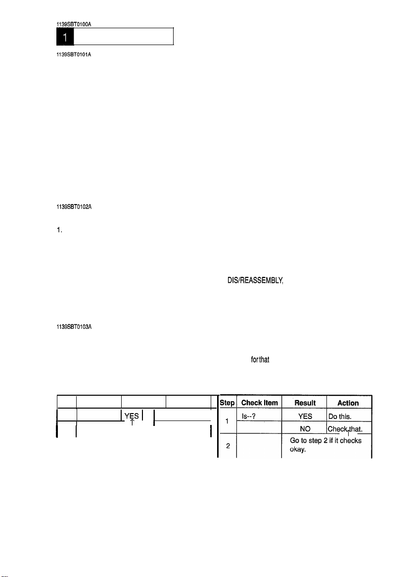
1-3. Reading the Text
1.
The paper
the location where the paper is present and start the procedure
troubleshooting, start with step 1 and onward.
2. Make checks in numerical order of steps and, if an item is checked okay, go to the next step.
Pattern 1
Step Check Item
1
2
I I
transport failure
Is--?
I
Go to step 2 if it checks okay.
troubleshooting procedures are given according to the symptom. First identify
Result
1 YFS 1
Do this.
Action
1
DISREASSEMBLY,
Pattern 2
11
I
ADJUSTMENT.
forthat
particular location. For malfunction
T-l
Page 5
1151SBT0200A
I/O
PORT CHECK
1158SBT0201A
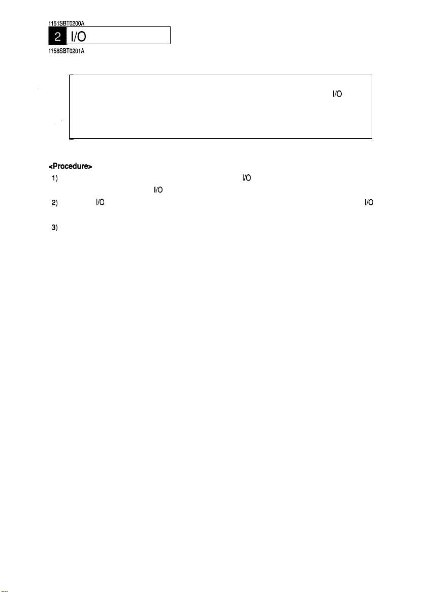
2-1. Controlled Parts Check Procedure
To allow the Tech. Rep. to easily and safely determine whether a particular controlled part is fully
operational, this copier provides the following provision: the check of the data of the
the board IC with the copier in the standby state (including a misfeed, malfunction, and closure
failure condition) allows the Tech. Rep. to determine whether a signal is properly input to, and
output from, a controlled part.
cProcedure>
When a paper misfeed or malfunction occurs, identify the
part by going over the text or
Select the
port identified in step 1).
Check the input or output port data to determine whether the controlled part is operational and signals
are properly input and output.
I/O
Check function of the Service mode and show on the Touch Panel the status of the
I/O
port check list.
I/O
port of the possibly defective controlled
I/O
port on
I/O
T-2
Page 6
---c_--~~----------------~----
Example:
<Procedure>
1)
2)
3)
4)
5)
6)
I
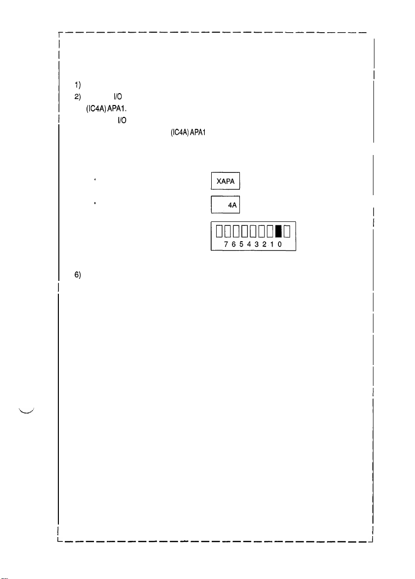
<Controlled Part Check Procedure by Changing Input Port Data>
When a paper misfeed occurs in the paper take-up section of the copier, Paper Take-Up
Sensor PC55 is considered to be responsible for it.
Remove the sheet of paper misfed.
From the
I/O
port check list, it is found that the H/L input signal to PC55 is supplied from PWB-A
(IC4A) APAI.
Select the
show the status of PWB-A
Checkthat the second LED from the right of the Exposure Information Display lights up (sensor
being unblocked).
Move the PC55 actuator to block the sensor.
Check at this time that the LED goes out.
I/O
Check function from the Service mode menu and, using the Paper Select key,
(IC4A) APAl
*
Zoom Ratio Indicator
.
Multi-Copy Display
. Exposure Information Display
ON: PC55 is faulty. OFF: PC55 is operational.
on the control panel.
1
L/
I
l-
-------__-__---___---_--__-__
J
T-3
Page 7
I
1158SBT0202A
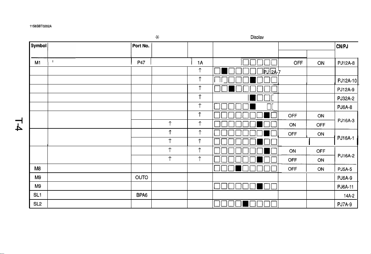
2-2. Port Check List
TI
P
(Copier)
Name
PC Drive Motor
PC Drive Motor lock signal
Ml
Main Drive Motor
M2
Main Drive Motor lock signal
M2
Optical Section Cooling Fan Motor
M3
Suction Fan Motor
M4
Scanner Motor
M5
Lena Motor
M6
Mirror Motor
M7
Toner Replenishing Motor
Ma
Cooling Fan Motor
M9
Cooling Fan Motor lock signal
M9
Separator Solenoid
SLl
Paper Take-Up Solenoid
SL2
1
BPA5 BPA
OUT0
APC2
BPA6
BPA4
33
1
st Drawer paper take-up LED on the Monitor
Magnification Multi-Copy
Ratio Indicator
P471
P4 1
P67
P43
P66 P6
P43 P4
P43
P61
P62
P61
P62
P61
P62
OUT
APC
BPA
BPA
P6
P4
P4
P6
Displav
liahts up.
Manual Exposure
Display
1A
q mclc
?
[7mcl1clclc
t
nnnnr
t
GIL--_
t
q ucloG_
1
cl00011
1
clclclnoo
?
?
t
1
t
1
cloclclclcl
1
cl0017cl10
t
nnnnnn
____--U[
1
I7noncl1oclmo
1
clcloouo~clo
4A
clclclmclclclclcl
5A
q clclnoooom
4A
~~~~~~~~
4A
q nanooooo OFF ON
4A
~~~~~~~~
Indicator
1~~~~~
~~~_
] n n
___.-lmI
]nn
lmnrlclcJclC
MIICIIC
q
Operation Characteristics
ON
OFF
When locked When turnedPJl2A-7
OFF ON
1
When locked When turned
OFF ON
1
OFF
1
CIC
I
InI
OFF ( ON
-When locked When turned
OFF ON
I
OFF ON
CN/PJ
OFF
ON
ON PJ6A-6
PJ12A-6
PJ12A-10
PJ12A-9
PJ32A-2
PJ16A-1
1
PJ6A-9
PJGA-11
PJ
14A-2
PJ7A-9
No.
1
I
Page 8
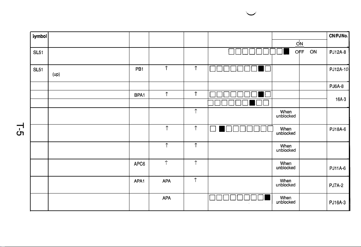
Symbol
SL51
Name
Manual Feed Paper Take-Up Solenoid
(down)
Port No.
PBO
Magnification Multi-Copy
Ratio Indicator Display
PB
4A
Manual Exposure
Indicator
tl~~~Ic]~~~
Operation Characteristics
OFF
,o, ON
CNlPJ No,
PJ12A-8
SL51
CL?
CL2
CL51
PC31
PC51
PC53
PC54
PC55
PC57
Manual Feed Paper Take-Up Solenoid
(up)
Synchronizing Roller Clutch
Paper Transport Clutch
Manual Feed Paper Take-Up Clutch
Manual Feed Paper Empty Sensor
Transport Roller Sensor
Paper Exit Sensor
Paper Leading Edge Detecting Sensor
Paper Take-Up Sensor
Right Door Detecting Sensor
PBl
BPAO
BPAl
PB2
APC3 APC
APC7
APC5
APC6
APAl
APAO
t
BPA
1
PB
1
1
f
APA
APA 4A When
1
~~~~0~~~
4A
q oouooonm
1
~~~~~~~~
5A
00n~~mnn
1
q oooomooo un;;ELed
t
q
mo~1ooooo
1
q oomooooo un;;ELed
1
q omoooooo
1
q oouonnmo
OFF ON
OFF ON PJ6A-8
OFF ON
OFF
un;;iced
un;;f=Led
unt;t-=Led
OFF
When
blocked
When PJ18A-6
blocked
When
blocked
When
blocked
When
blocked
blocked
PJ12A-lt
PJ
16A-3
PJ21 A-2
PJllA-6
PJ7A-2
PJ16A-3
Page 9
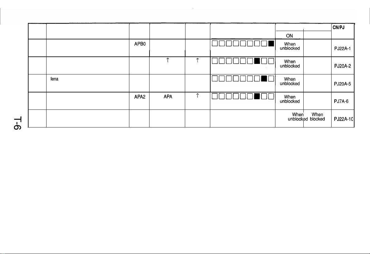
Symbol
PC81
Name
Scanner Reference Position Sensor
Port No.
APB0 APB 4A
Magnification Multi-Copy
Ratio Indicator
Display
Manual Exposure
Indicator
Operation Characteristics
OFF
When
blocked
CN/PJ
PJ22A-1
No.
PC86
PC90
PC101
PC112
Mirror Reference Position sensor
lena
Reference Position Sensor
Paper Empty Sensor
Toner Hopper Home Position Sensor
APB2
APB1 APB 4A
APA
APB6
*r
APA
APB
t
1
4A
q oonnooo
When
blocked
When
blocked
When
blocked
ur$%ed bEEE:d
PJ20A-2
PJ20A-5
PJ7A-6
PJ22A-10
Page 10
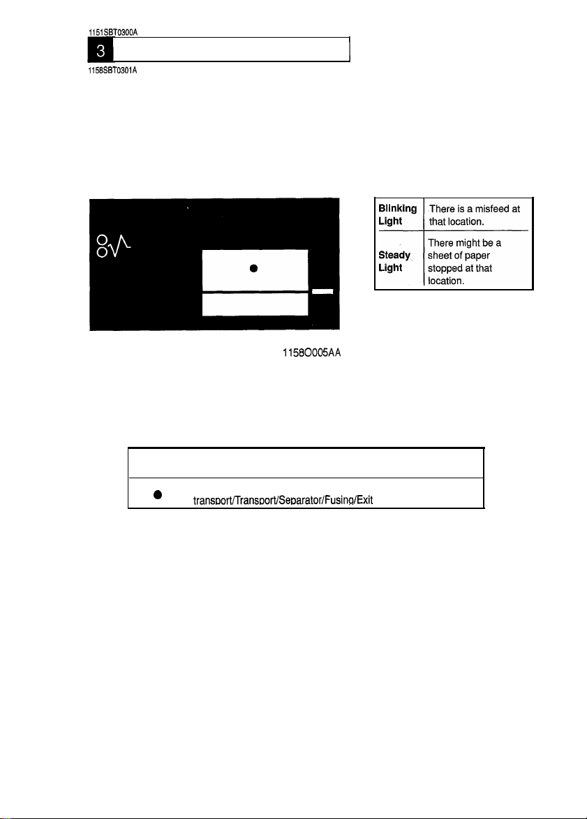
1151SBT0300A
PAPER TRANSPORT FAILURE
1158SBT0301A
1. Paper Misfeed
When a paper misfeecl occurs in the copier, the corresponding Misfeeci Location Monitor LED on
the control panel blinks to let the user know where the misfeed has occurred. If an LED lights up
steadily, it indicates that there might be a sheet of paper present at that particular location in the
copier. If a paper misfeed occurs very frequently, carry out the necessary troubleshooting
procedures according to the location of the misfeed.
1
Blinking
LED
0
Blinking
Light
Steady
Light
-I--
11580005AA
Misfeed Locatlon
Paper take-up/Bypass port/Vertical
transoort/Transoort/SeDarator/Fusinn/Exit
There is a misfeed at
that location.
There might be a
sheet of paper
stopped at that
location.
T-7
Page 11
I
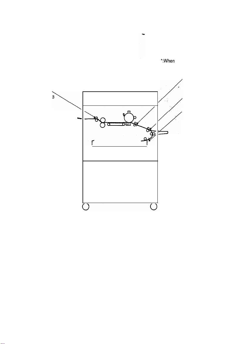
The paper misfeed, is detected by the following sensors.
Paper Exit
Sensor PC53
\
-
*:When
option is installed
(Exit/Duplex Switching Unit)
Paper Leading
I
Edge Detecting
Sensor PC54
/
/
Transport Roller
Sensor PC51
Paper Take-Up
Sensor PC55
4
T-8
Page 12
l
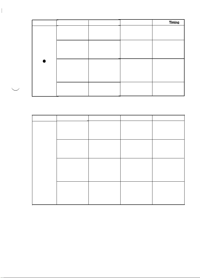
Here is an at-a-glance listing of misfeed detections made by the various sensors of the copier.
A: Misfeed Detected in Conjunction with Leading Edge Detection
Sensor
Blinking LED
0
B: Misfeed Detected in Conjunction with Trailing Edge Detection
Blinking LED
l
Location
Before the Paper
Take-Up Sensor
Before the
Transport Roller
Before the Paper
Leading Edge
Detecting Sensor
From Image
Transfer Corona to detection by the
Fusing Unit
Location
Vertical Transport
Section
Near the Transport
Roller Sensor
Near the Paper
Leading Edge
Detecting Sensor
From the Suction
to Fusing Unit
Description
Take-up failureIPaper take-up start
Leading edge
detection by the
Transport Roller
Sensor Sensor
Leading edge
detection by the
Paper Leading
Edge Detecting
Sensor
Leading edge
Paper Exit Sensor
Description
Trailing edge
detection by the
Paper Take-Up
Sensor
Trailing edge
detection by the
Transport Roller
Sensor
Trailing edge
detection by the
Paper Leading
Edge Detecting
Sensor
Trailing edge
detection by the
Paper Exit Sensor
Timer Start
Leading edge
detection by the
Paper Take-Up
Leading edge
detection by the
Transport Roller
Sensor
TRON signal
Timer Start Sensor Timing
Leading edge
detection by the
Paper Take-Up
Sensor
TRON signal
Trailing edge
detection by the
Transport Roller
Sensor
Trailing edge
detection by the
Paper Leading
Edge Detecting
Sensor
Paper Take-Up
Sensor
(leading edge)
Transport Roller
Sensor
(leading edge)
Paper Leading
Edge Detecting
Sensor
(leading edge)
Paper Exit Sensor
(leading edge)
Paper Take-Up
Sensor
(trailing edge)
Transport Roller
Sensor
(trailing edge)
Paper Leading
Edge Detecting
Sensor
(trailing edge)
Paper Exit Sensor
(trailing edge)
Timing
T-9
Page 13
1158SBT030101A
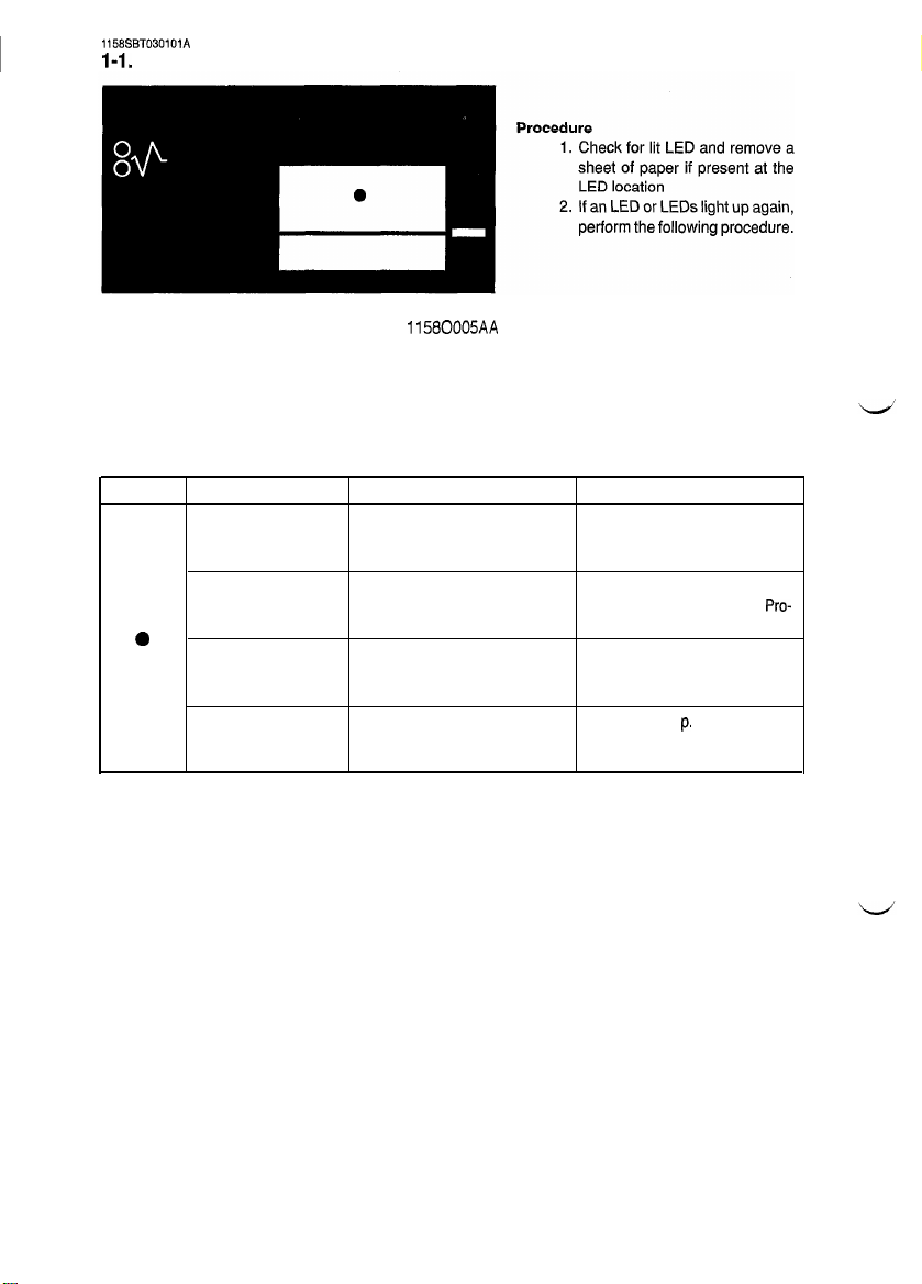
I-1. Misfeed Detected When Copier is Turned ON
11580005AA
Lit LED Paper Location Sensor
Drawer
Transport Roller
a
Synchronizing Roller Paper Leading Edge See step 2 on p. T-i 7
Exit Section Paper Exit Sensor PC53 See step 8 on p. T-20
Paper Take-Up Sensor PC55
Transport Roller Sensor PC51
Detecting Sensor PC54
Action
See step 10 on p. T-i 3 (Copier
Take-Up Misfeed Clearing Procedure).
See step 14 on p. T-l 3 (Copier
Take-Up Misfeed Clearing
cedure).
(Transport/Separator Misfeed
Clearing Procedure).
(Fusing/Exit Misfeed Clearing
Procedure).
Pro-
T-10
Page 14
1158SBT030102A
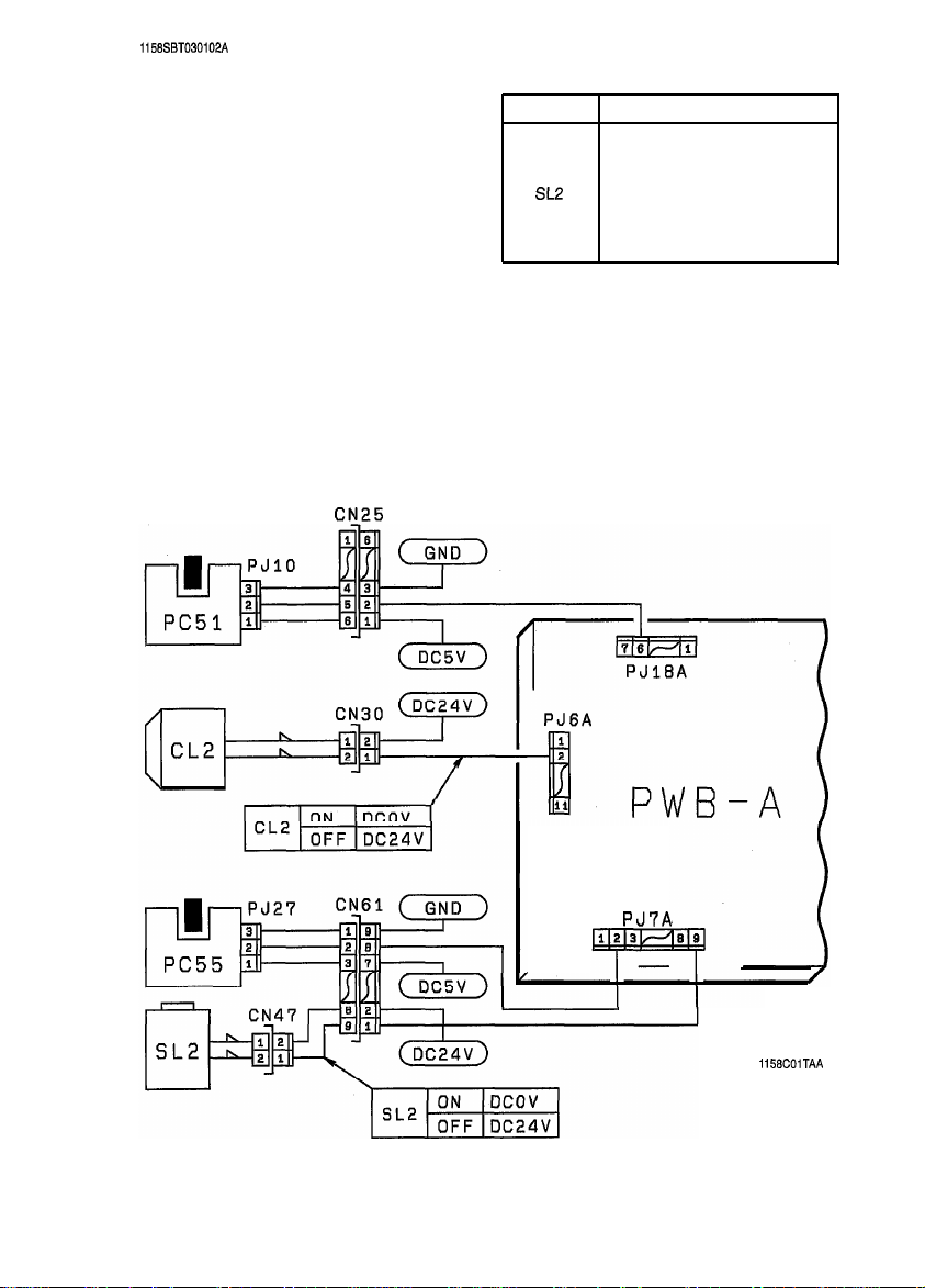
1-2. Copier Take-Up Misfeed
CN_25
Symbol
PC51
PC55
SL2
CL2
PWB-A
Transport Roller Sensor
Name
Paper Take-Up
Sensor
Paper Take-Up
Solenoid
Paper Transport Clutch
Main Control Board
T-11
PJ7A
L
1158COlTAA
Page 15
+
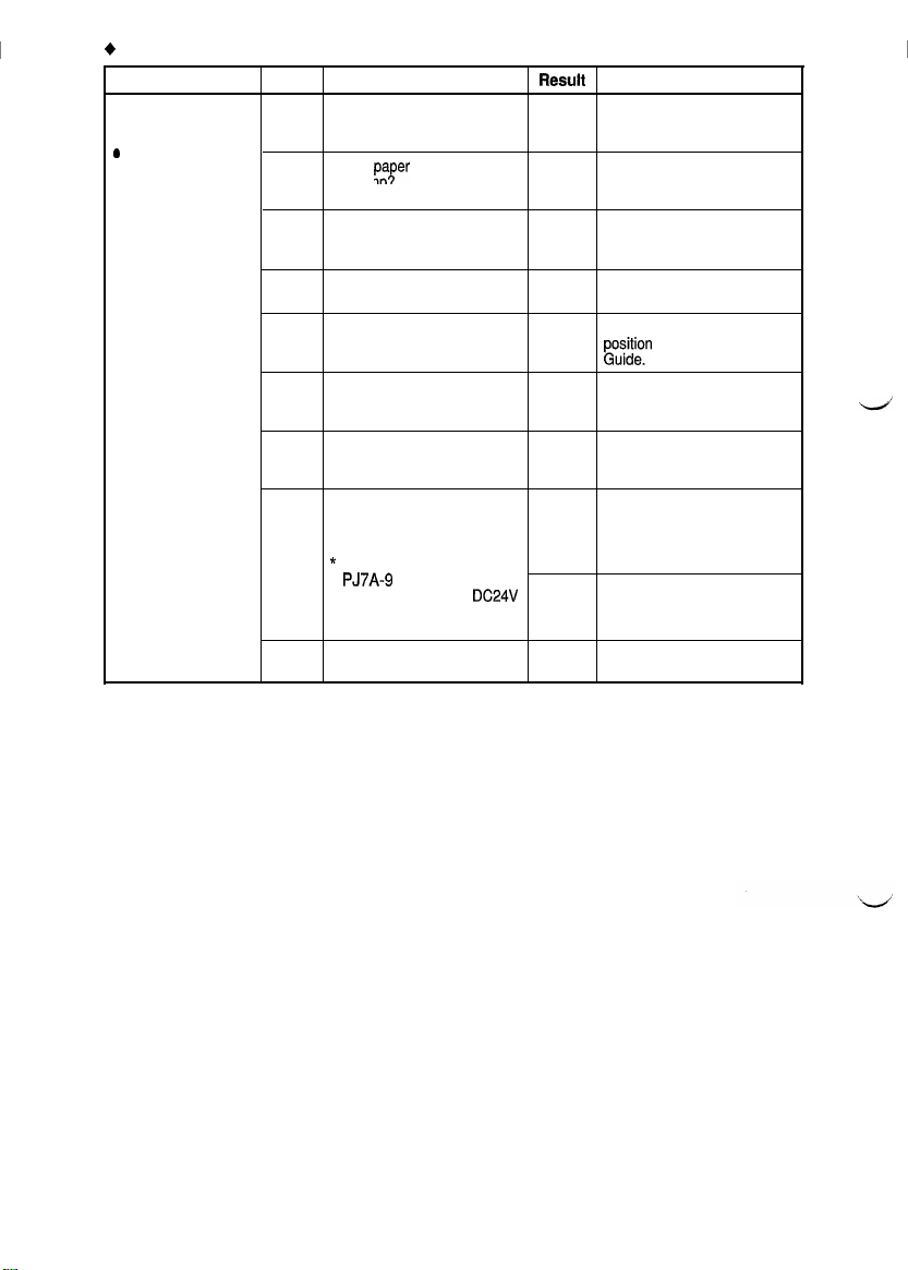
Copier Take-Up Misfeed Clearing Procedure
Symptom
l
Paper is not taken
up at all.
0
Paper is
stationary before
the Paper
Take-Up Sensor.
Continued on next page
Step Check Item
Is the paper being used up
1
to product specifications?
Is the pafer curled, waved,
or damp.
2
Are the Separator Fingers
3
on both sides of the Drawer
in position?
Are the Separator Fingers
4
deformed?
Is the Trailing Edge Stop or
5
Edge Guide in good
position?
Are the Paper Lifting
6
Springs positioned
correctly?
Are the Paper Take-Up
7
Rolls deformed, worn, or
dirty with paper dust?
Is a signal being output
from PWB-A to the Paper
Take-Up Solenoid?
8
*
Does the voltage across
PJ7A-9
on PWB-A and
GND change from
to DCOV when the Start
Key is pressed?
Is the Clutch Spring
9
deformed or worn?
DC24V
R@SUll:
Instruct the user to use the
NO
paper that is up to product
specifications.
Change the paper.
YES
Instruct the user in how to
store the paper.
Instruct the user to load the
NO
paper so that it rests under
the Fingers.
Replace the Fingers.
YES
Instruct the user in how to
NO
gu;)stn
the Edge Stop or
Change the position of the
NO
Spring or add one as
necessary.
Clean or replace the Paper
YES
Take-Up Rolls.
Adjust the Solenoid stroke.
Check the Solenoid.
YES
Replace PWB-A.
NO
Replace the Clutch Spring.
YES
Action
T-12
Page 16
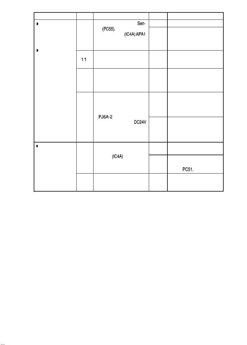
Symptom
D
Paper is
stationary before
the Vertical
Transport Roller.
D
Paper is
stationary at the
Vertical Transport
Roller.
step
10
1 1
12
13
Check Item Result Action
YES
Check Paper Take-Up
sor
(PC55).
PC55: PWB-A
Are the Vertical Transport Clean or replace the
Rollers deformed, worn, or
dirty with paper dust?
Are the Paper Take-Up Clean, correct, or replace
Guide Plate and Vertical
Transport Guide Plate dirty
or deformed?
Is a signal being output
from PWB-A to the Clutch?
* Does the voltage across
Seep.T-3.
PJ6A-2
on PWB-A and
GND change from
to DCOV when the Start
Key is pressed?
Sen-
(IC4A) APAl
DC24V
Replace PWB-A.
Check the Actuator for
operation.
NO
Check the Paper Take-Up
Sensor.
Vertical Transport Rollers.
YES
the Guide Plate.
YES
Check the Clutch.
YES
Replace PWB-A.
NO
D
Paper is
stationary near
the Transport
Roller.
Check Transport Roller Replace or check the
Sensor PC51 See p. T-3
(PWB-A
(IC4A)
14
Are the Transport Rollers
deformed, worn, or dirty
15
with paper dust?
APC7).
YES
PWB-A.
Check the Actuator for
operation.
NO
Check
Clean or replace the
Transport Rollers.
YES
PC51.
T-13
Page 17

I
1158SBT030103A
1-3. Bypass Port Misfeed
Symbol
PC51
Transport Roller Sensor
Name
T-14
1151COPTAA
Page 18

+
I
Bypass Port Misfeed Clearing Procedure
Symptom
D
Paper is not taken
up at all.
I Paper is
stationary near
the Transport
Roller.
step
1
2
3
4
5
6
7
a
9
10
11
Check Item Result
Does the misfeed occur Perform the troubleshooting
when the Manual Bypass
Table is used? Transport/Separator
Is paper taken up and fed in
properly from the Drawer? procedure for Copier
Is the paper being used up
to product specifications?
Is the paper curled, waved, Change the paper.
or damp?
Are the Paper Take-Up Adjust the stroke of the
Rolls pressed against the Solenoid.
paper stack when the Start
Key is pressed?
* Does the voltage across
PJli A-2
on PWB-A and
GND change from
to DCOV when the Start
Key is pressed?
Does the voltage across Check the Clutch.
PJ7A-5
on PWB-A and
GND change from
to DCOV when the Start
Key is pressed?
Is the Pressure Pad or
Guide Plate deformed or YES Pressure Pad or Guide
dirty?
Are the Paper Take-Up
Rolls deformed, worn, or
dirty with paper dust?
Check Transport Roller Check the Actuator for
Sensor PC51 Seep. T-3
(PWB-A
(IC4A)
Does the voltage across Check the Clutch.
PJ6A-6
on PWB-A and
GND change from
to DCOV when the Start
Key is pressed?
Is the Transport Roller or
Guide Plate of the copier
deformed, worn, or dirty
with paper dust?
DC24V
DC24V
APC7).
DC24V
Action
procedure for
YES
Misfeed.
Perform the troubleshooting
Take-Up and
NO
Transport/Separator
Misfeed.
Instruct the user to use the
paper that is up to product
NO
specifications.
YES
Instruct the user in how to
store the paper.
Check the Solenoid.
YES
Replace PWB-A.
NO
YES
Replace PWB-A.
NO
Clean or replace the
Plate.
Clean or replace the Paper
Take-Up Rolls.
YES
operation.
NO
Check
PC51.
YES
Replace PWB-A.
NO
Clean or replace the
Vertical Transport Roller or
YES
Guide Plate.
T-15
Page 19

1158SBT030104A
l-4.
Transport/Separator Misfeed
Symbol
PC51
PC54
SLl
CL1
M3
PWB-A
Transport Roller Sensor
Name
Paper Leading Edge Detecting
Sensor
Separator Solenoid
Synchronizing Roller Clutch
Suction Fan Motor
Main Control Board
PWB-
T-16
A
1151C24TAA
Page 20

+
I
Transport/Separator Misfeed Clearing Procedure
Symptom
l
Paper is
stationary before 1
the Synchronizing
Roller.
@
Paper is
stationary near
the PC Drum.
Step Check Item
Is the paper curled, waved, Change the paper.
or damp?
Check Paper Leading Edge
Detecting Sensor PC54
2
See p. T-3 (PWB-A
APCG).
Do the Synchronizing
Rollers turn?
* Does the voltage across
3
PJ6A-4
on PWB-A and
GND change from
to DCOV after the Start
Key has been pressed?
Is a given length of loop Adjust the loop length or
4
formed before the
Synchronizing Roller? Transport Rollers.
Is the Pre-Image Transfer Correct or clean the Guide
Guide Plate deformed or
5
dirty?
Is the Corona Unit Cleaning Place the Lever in position.
Lever (Lower) in correct
6
position?
Are the Image
Transfer/Paper Separator
7
Corona Wires deteriorated
or dirty?
Are the Paper Guides
8
deformed or dirty?
Are the Synchronizing Clean or replace the
Rollers deformed, worn, or
9
dirty with paper dust?
(IC4A)
DC24V
Result Action
YES instruct
YES Replace PWB-A.
NO
YES
NO
NO
YES
NO
YES
YES
YES
the user in how to
store the paper.
Check the Actuator for
operation.
Check PC54.
Check the Clutch.
Replace PWB-A.
clean or replace the
Plate.
Clean or replace the Wires.
Clean or replace the Paper
Guides.
Synchronizing Rollers.
T-17
Page 21

Symptom
D
Paper is wedged
at the Paper
Separator Fingers.
B
Paper is
stationary before 12
the Suction Belts.
Step
1 o
11
13
14
15
Check Item
Does the voltage across Adjust the Solenoid, or
PJI 4A-2
on PWB-A and
GND change from
to DCOV after the Start Key
has been pressed?
Are the Paper Separator
Fingers deformed or dirty?
Check Transport Roller Check the Actuator for
Sensor PC51 See p. T-3
(PWB-A
(IC4A)
Check Paper Leading Edge YES
Detecting Sensor PC54
See p. T-3
(PWB-A
Do the Suction Belts turn
properly?
Is Suction Fan Motor M4
turning when the Start Key Check M4.
is pressed?
* Does the voltage across
PJ6A-8
on PWB-A and
GND change from
to DCOV when the Start
Key is pressed?
DC24V
APC7).
(IC4A) APCG).
Result Action
YES
NO Replace PWB-A.
YES
NO
NO
YES
YES
DC24V
No
check the Paper Separator
Fingers for operation and
clearance.
Correct or clean, or replace,
the Paper Separator
Fingers.
operation.
Check
Replace PWB-A.
Check the Actuator for
operation.
Check PC54.
Check the Belts and Drive
Gear.
Check the
Replace PWB-A.
PC51.
DC24V
line.
T-18
Page 22

1158SBT030105A
l-5. Fusing/Exit Misfeed
T-19
1158C02TAA
Page 23

6
F~rsindFxit
_ . __...
J, -
hllinfnnri
,... . . .._.___
Symptom
l
Paper is
stationary before 1
the Fusing Roller.
*The leading edge
of the paper is
stationary near
the Fusing Roller.
l
Paper is
stationary after
the
Paper
Exit
Roller/Rolls.
Clnnrinn Procedure
-.--a
.__---._
.
Step
Is the paper curled, waved,
or damp?
Is the Guide Plate dirty with
2
toner?
Do the Suction Belts turn
3
properly?
Is Suction Fan Motor M4
turning when the Start Key
is pressed?
4
* Does the voltage across
PJ6A-8
GND change from
to DCOV when the Start
Key is pressed?
Are the Fusing Rollers
scratched or dirty? Or, has
5
the replacement time
arrived for the Rollers?
Are the Paper Separator
Fingers dirty with toner or
6
worn? Are their edges
damaged?
Is the Oil Roller dirty? Or,
has the replacement time
7
arrived for the Roller?
Check Paper Exit Sensor
(PC53) See p. T-3.
8
PC53:
Check Paper Leading Edge
Detecting Sensor PC54
9
See p, T-3 (PWB-A
APCG).
Check
Item
on PWB-A and
DC24V
PWBA (IC4A)
Al%5
(IC4A)
Result Action
Change the paper.
Instruct the user in how to
YES
store the paper.
Clean the Guide Plate.
Check for possible
YES
scattering of toner.
Check the Belts and Drive
YES
Gear.
Check the
DC24V
Check M4.
YES
Replace PWB-A.
No
Clean or replace the Rollers.
YES
Clean or replace the
Fingers.
YES
Clean or replace the Roller.
YES
Check the Actuator for
operation.
NO
Check PC53 or both.
Replace PWB-A.
YES
Check the Actuator for
NO
operation.
Check PC54.
line.
T-20
Page 24

1151SBT0302A
2. Wrinkles in Paper
!
step Cause
Paper
1
Paper Take-Up
Section
2
Transport Section
3
4
Pre-Fusing
Guide Plate toner or other foreign matter? YES
Check Item Result
Is the problem solved when
new paper is used?
Is
the paper taken up and Check the Drawer and Paper
fed in properly?
Are any of the Belts left slack
or the Suction Deck dirty?
Is the Guide Plate dirty with
Change the paper (that is up
to product specifications).
YES
Instruct the user in how to
store the paper.
Take-Up Rolls and adjust,
NO
clean, and/or replace the parts
as necessary. (See Skewed
Feed that appears later.)
Replace the three Belts at
YES once or clean the Suction
Deck.
Clean the Guide Plate.
Action
5
6 s
-LL
7
8
1158SBT0303A
Thermistor Is the Thermistor damaged
C
?
._
2
Fusing Rollers Has the Roller replacement
Width of area Does the location of wrinkles Replace the two Pressure
of contact
between the
Upper and
Lower Fusing
Rollers
or dirty with toner?
Is the Thermistor in positive
contact with the Upper
Fusing Roller?
time arrived?
change when the position of Springs at once.
the left and right Pressure
Springs are changed?
Clean or replace the
YES
Thermistor.
Move the Thermistor Mounting
Bracket up or down as
necessary so that the
NO
Thermistor comes in positive
contact with the Upper Fusing
Roller.
Replace the Rollers.
YES
YES
3. Double Feed
Step Cause
Paper Is the problem solved when Change the paper (that is up
1
g
Paper
g
Take-Up Roll
2 w
3
d,
3
Paper
z Separator Roll dirty?
3
B
a
Check Item
new paper is used?
Is the Paper Take-Up Roll Clean or replace the Paper
dirty, or has its replacement
time arrived?
Is the Paper Separator Roll
Result
to product specifications).
YES
Instruct the user in how to
store the paper.
Take-Up Roll.
YES
Clean or replace the Paper
Separator Roll.
YES
Action
T-21
Page 25

I
1158SBT0304A
4. Skewed Feed
Step Cause
Paper
1
5
Paper
.g
Take-Up Roll
2
G
9
s
$
3
Paper
3
a
Separator Roll dirty?
Paper Dust Is the Paper Dust Remover Clean the Paper Dust
4
5
-lz
6
7
8
Remover
Transport Are the Transport Rollers
g
Rollers
9
8
UI
g
Synchronizing
2
Rollers
$
Suction Unit Are any of the Belts left slack Replace the three Belts at
Pre-Fusing Guide
Plate toner or other foreign matter?
Check Item Result
Is the problem solved when
new paper is used?
Is the Paper Take-Up Roll Clean or replace the Paper
dirty, or has its replacement
time arrived?
Are the Paper Take-Up Rolls
located correctly? (For the
Copiers 1 st Drawer)
Is the Paper Separator Roll
dirty with paper dust?
dirty or worn? Or Has their
replacement time arrived?
Are the Synchronizing
Rollers dirty or worn? Or Has Adjust Mode.
their replacement time
arrived? Synchronizing Rollers.
or the Suction Deck dirty? YES once or clean the Suction
Is the Guide Plate dirty with
Change the paper (that is up
to product specifications).
YES
Instruct the user in how to
store the paper.
YES
Take-Up Roll.
Change the locations of the
YESFRolls according to the paper
size being used
Clean or replace the Paper
YES
Separator Roll.
YES
Remover and Upper
Synchronizing Roller.
Adjust the loop length in the
Adjust Mode.
YES
Clean or replace the Transport
Rollers.
Adjust the loop length in the
YES
Clean or replace the
Deck.
Clean the Guide Plate.
YES
Action
T-22
Page 26

1151SBT0400A
MALFUNCTIONS
1158SBT0401A
1. Self-Diagnostic Function
The copier CPU is capable of self-diagnosis of the copier conditions and, when detecting a malfunction, it
shows the corresponding malfunction code across the Zoom Ratio Indicator and Multi-Copy Display. Each
malfunction code indicates the particular part which has developed a malfunction and the type of
malfunction.8 listing follows showing all malfunction codes and the description and possible causes of each
malfunction.
Zoom Ratio Indicator
I
Multi-Copy Display
n
coxxx
Represents the detail of malfunction.
Indicates the particular malfunctioning unit of
TT’
*
Copier/Paper Feed Cabinet (Option)
Description
Main Drive Motors failurel Defective M2
to turn
Main Drive Motor turningl Defective M2
at abnormal timing
PC Drive Motors failure to
turn
PC Drive Motor turning at
abnormal timing
Cooling Fan Motors
failure to turn
Toner Replenishing
Motors failure to turn
Toner Replenishing Motor
turning at abnormal timingl Defective M8
,g
B
Code
coooo
coo01
coo1 0
coo11
coo4c
coo70
co711
the greater physical unit.
Indicates the malfunctioning physical unit.
Possible Cause
l
Defective PWB-A
l
Overloaded rolls/roller,
l
Defective PWB-A
l
Defective
l
l
l
l
l
l
l
l
l
l
l
Ml
Defective PWB-A
Overloaded gear
Defective
Ml
Defective PWB-A
Defective
M9
Defective PWB-A
Defective Toner Hopper Position Sensor PC1 12
Defective M8
Defective PWB-A
Defective Toner Hopper Position Sensor PC1 12
Defective PWB-A
aear,
and belt
T-23
Page 27

Lens
Motor malfunction
l
Defective Lens Motor M6
l
Defective Lens
Reference Position Sensor PC90
Position Sensor
T-24
Page 28

Page 29

1151SBT040101A
I-l. COOOO: Main Drive Motors failure to turn
COOOI:
Main Drive Motor turning at abnormal timing
1
Symbol
M2
I
PWB-A
1
Main Drive Motor
Main Control Board
Nat& 1
I
PJ12A
1151C18TAA
T-25
Page 30

Step
Is COO01 being shown? YES
1
Does M2 start to turn when the Start
2
Key is pressed?
Does the voltage across
PWB-A and GND change from
3
to DCOV when the Start Key is
pressed?
Does the voltage across
4
PWB-A and GND remain
the Start Key is pressed?
Does the voltage across
PWB-A and GND remain DCOV when
5
the Power Switch is turned ON?
Does the voltage across
6
PWB-A and GND remain DCOV when
the Power Switch is turned ON?
Check Item
PJ12A-10
PJ12A-9
DC5V
PJl2A-10
PJl2A-9
on
DC5V
on
when
on
on
Result Action
Begin with step 5.
Check rolls/rollers and gears for
YES
possible overload.
Replace PWB-A.
NO
Replace M2.
YES
Replace PWB-A.
NO
Replace PWB-A.
YES
Replace M2.
YES
Replace PWB-A.
NO
T-26
Page 31

1151SBT040102A
1-2.
COOIO:
PC Drive Motors failure to turn
COO11 : PC Drive Motor turning at abnormal timing
8m!4
Rotat
M1 fhtu#
Lock
ON
M1 OFF
I on
DClJv
DC5V
DCOV \
DC24V
+h
GND )
I
PWB-A
1151C17TAA
T-27
Page 32

Step
1
Is COO11 being shown?
Does Ml start to turn when the Start
2
Key is pressed?
Does the voltage across
PWB-A and GND change from
3
to DCOV when the Start Key is
pressed?
Does the voltage across
4
PWB-A and GND remain
the Start Key is pressed?
Does the voltage across
PWB-A and GND remain DCOV when YES
5
the Power Switch is turned ON?
Does the voltage across
6
PWB-A and GND remain DCOV when
the Power Switch is turned ON?
Check Item
PJ12A-8
PJI 2A-7
DC5V
PJI 2A-8
PJ12A-7
on
DC24V
on
when
on
on
Result
YES
YES
NO
YES
NO
YES
NO
Action
Begin with step 5.
Check gears for possible overload.
Replace PWB-A.
Replace Ml.
Replace PWB-A.
Replace PWB-A.
Replace M
Replace PWB-A.
1.
T-28
Page 33

1151SBT040103A
1-3.
COO4C:
Cooling Fan Motors failure to turn
f@B@il4
Ful
I-Speed DC24V
Rotation
M9
+~El$L?E~
Half-Speed DC12V
Rotation
Symbol
M9 Cooling Fan Motor
PWB-A
Main Control Board
Name
Y
M9
1151C16TAA
T-29
Page 34

coo4c
Step
1
2
3
Check Item Result Action
Is MS turning at low speed when the
Power Switch is in the ON position?
Does the voltage across
PWB-A and GND change from DC1 2V
to
DC24V
when the Start Key is
pressed?
Is the voltage across
A and GND DC1 2V when the Power
Switch is in the ON position?
PJ6A-9
PJ6A-9
on
on
PWB-
NO
YES
NO
YES
NO
Begin with step 3.
Replace
M9.
Replace PWB-A.
Replace
M9.
Replace PWB-A.
T-30
Page 35

1151SST040104A
1-4.
COO70:
Toner Replenishing Motors failure to turn
COO71 : Toner Replenishing Motor turning at abnormal timing
I
PJGA
Symbol
PC112
M8
PWB-A
Toner Hopper Home Position
Name
Sensor
Toner Replenishing Motor
Main Control Board
PJ22A
T-31
1151C09TAA
Page 36

Step
1
Is COO71 being shown?
Does the Toner Bottle turn when two
2
or three
Original Cover raised?
Make two or three copies with the
Original Cover raised. Does the
voltage across
and GND change to DCOV when the
3
Toner Bottle is stopped and to
when the Bottle is turned during the
copy cycle?
Make two or three copies with the
Original Cover raised. Does the
voltage across
and GND change to DCOV when the
4
Toner Bottle is stopped and to
when the Bottle is turned during the
copy cycle?
Check Item Result Action
copies are made with the
PJ22A-10
PJ6A-5
on PWB-A
on PWB-A
DC5V
DC24V
YES
Begin with step 3
Perform step 3.
YES
Perform step 4.
NO
Replace PWB-A.
YES
Check the Bottle Holder or PC1 12.
NO
Replace M8.
YES
Replace PWB-A.
NO
T-32
Page 37

1151SBT040105A
l-5.
CO400:
CO410:
Exposure Lamps failure to turn ON
Exposure Lamp turning ON at abnormal timing
Symbol
LA1
TF2
PWB-A
PWB-H
PUl
Exposure Lamp
Exposure Lamp Thermal Fuse
Main Control Board
AE Sensor Board
Power Supply Unit
Name
or
T-33
1151C03TAA
Page 38

co400
Step
1
2
3
4
co41 0
Step
A
B
I
Does LA1 light up when the Start Key
is pressed?
Does the voltage across
PWB-A and GND become
less when LA1 turns ON?
Disconnect CN7
continuity across
LA1 side?
Is the voltage across
PUl
AC1 OOV?
I
Does LA1 turn ON when the Power Check to see if the photo receiver of
Switch is turned ON or in the standby
state?
Does the voltage across
PWB-A and GND remain
lower when the Power Switch is turned
ON or in the standby state?
Check Item
(2P).
Is there
CN7-1
and 2 on the
PJ2-1
Check Item
PJ12A-11
DC4.3V
and 2 on
PJ12A-11
DC4.3V
or
on
or
on
I
Result
I
Check the photo receiver of the AE
YES
Sensor for contamination.
I
I
I
Result
!
Replace PWB-H or PWB-A.
I
Replace PWB-A.
Check LA1 and TF2 for continuity.
NO
I
YES Replace
Check DC Power Supply Unit PU2 and
NO
Power Supply Board PWB-C.
I
the AE Sensor is receiving extraneous
NO
light.
Replace PWB-H or PWB-A.
!
PUl
Action
.
Action
T-34
Page 39

1151
SBT040106A
1-6.
CO500:
co51 0:
co520:
Warming-up failure
Abnormally low fusing temperature
Abnormally high fusing temperature
T-35
1151C14TAA
Page 40

co500,
co51 0
* After resetting a CO51 0 condition, CO500 will be shown if the same problem recurs. For this reason, the
same troubleshooting procedure is used for CO500 and CO51 0.
Step
Does HI light up when the Power
1
Switch is turned ON?
I
1
Disconnect CN14 (4P). Is the
2
resistance across
THl
side infinity?
Does the voltage across
PWB-A and GND change from
to DCOV when the Front Door is closed
3
with the Power Switch in the ON
position?
-1
Disconnect CN5 (2P). Is there
4
continuity across
Fusing Unit side?
CO520
Step
Does Hl remain lit up even after the YESABegin with step B.
copier has completed warming up?
Does the voltage across
PWB-A and GND remain DCOV even
B
after the copier has completed
warming up?
1
Disconnect CN14 (4P). Is the circuit1
I
C
across CNl4-2 and 3 on the Fusing
Unit side short-circuited?
Check Item
CNl4-2
CN5-1
Check Item Result Action
and 3 on the
PJ3A-2
on
DC4.5V
and 2 on the
PJ3A-2
on
Result
YES
Check
THl
for installation or clean it.
NO
I
Begin with step 3.
I -
Replace
YES
NO
1
Replace
Replace PWB-A.
THl
PWB-A.
NO
Check Hl and
NO
Begin with step C.
NO
Replace PWB-A.
YES
Replace
UNl.
THl.
Replace PWB-A.
YES
NO
NO
1
Replace
Action
.
TFl
for continuity.
I
I
T-36
Page 41

1151SBT040107A
I-7.
CO600:
CO61 0:
CO620:
Scanner Motor malfunction
Lens Motor malfunction
Mirror Motor malfunction
JIE
Symbol
M5
M6
M7
PC81
PC86
PC90
PWB-A
PWB-E
I
Scanner Motor
Lens Motor
Mirror Motor
Scanner Reference Position
Sensor
Mirror Reference Position
Sensor
Lens Reference Position Sensor
Main Control Board
Motor Drive Board
1
Name
T-37
PJ22A
PWB-A
1151C13TAA
Page 42

I
CO600
step
1
2
3
CO61 0
Step
A
B
C
D
Check Item Result Action
Does the Scanner start moving after
the Power Switch has been turned ON?
Does the voltage across
PWB-A and GND change from
to DCOV after the Power Switch has
been turned ON?
Check Scanner Reference Position
Sensor
PC81.
See p, T-3 (PWB-A
1
Does M6 start turning after the Power
Switch has been turned ON?
Does the voltage across
PWB-A and GND change from
to DCOV after the Power Switch has
been turned ON?
Is the voltage across
PWB-E and GND
Power Switch has been turned ON?
Check Lens Reference Position
See p. T-3 (PWB-A
Check Item Result
PJ16A-3
(IC4A)
APBO)
PJ16A-1
PJ3E-5
DC24V
on
after the
(IC4A)
APBl) YES
on
DC5V
on
DC5V
PC90.
YES
YES
NO
YES
NO
YES
I
NO
YES
NO
NO
Perform step 3.
Replace PWB-E or M5.
Replace PWB-A.
Check the Scanner Drive Cable for
tension and overload. Or, replace
PWB-A.
Check
PC81,
Action
Perform step D.
I
Replace PWB-A.
Replace PWB-E or M6.
Check the 24V line.
Check the Lens Drive Cable for
tension and overload. Or, replace
PWB-A.
Check
PC90.
step
Does M7 start turning? YES Perform step III.
I
Does the voltage across
PWB-A and GND change from
II
to DCOV when the Mirror moves?
Check Item Result
PJ16A-2
on
DC5V
Reference Position PC86.
(PWB-A
(IC4A)
APB2)
YES
NO
YES
NO
T-38
Action
Replace PWB-E or M7.
Replace PWB-A.
Check for overload. Or, replace
PWB-A.
Check PC86.
Page 43

1158SBT040084A
1-8.
COFI
COF30:
Faulty
AE
0:
ATDC Sensor malfunction
Sensor level
CN39
UN3
1151ClOTAA
T-39
Page 44

I
COFlO
Step
1
COF30
Step
A
B
and
and
Check Item
PJl2A-3
DC4V
when the Start Key is
Check Item
PJl
A-3 on
DC4.5V
after the Start
on
~_
Is the voltage across
PWB-A and GND in the range between
DC2V
pressed in the F3 operation?
Is the voltage across
PWB-A and GND DCOV after the
Power Switch has been turned ON?
Is the voltage across PJl A-3 on
PWB-A and GND in the range between
DC0.5V
Key has been pressed?
Result
1 ~~
/
~~~~
/
Result Action
YES
YES
NO
PWB-A.
Check the photo receiver of the AE
Sensor for contamination or replace
Check the ATDC Sensor and the
connection between the Imaging Unit
and copier.
Replace PWB-A.
Replace the ATDC Sensor.
Action
I
T-40
Page 45

1158Si3T040109A
1-9. COF02: Original size detection error (Defective CPU)
COFEP
to COFFF: Original Size Detecting Sensor failure
Original Size Detecting Sensor
FD2
Original Size Detecting Sensor
CD1
Original Size Detecting Sensor
FD3
Original Size Detecting Sensor
CD2
Original Size Detecting Board
Master Board
Name
I--l
PJ43
1
PJ5
8
PJ
1151C09TAA
T-41
Page 46

Check
Step
Is any code from among COFE2 to
COFFF being shown?
Are jumper straps installed in the
following position for Jl and J2 of
2
Jl
:
On the end not marked with 0
J2: On the end not marked with 0
Does the LED of
3
(IC5A)
PA3 blink after the Power
Switch has been turned ON?
Is the Sensor located at the correct
4
position?
Does the problem persist even after
the corresponding Sensor has been YES
5
replaced?
Item
I/O
port check PWB-A
UN2?
Result
Perform step 4.
YES
Change the strap position of Jl and
NO
Replace PWB-A.
YES
Replace UN2.
NO
Change the position of the Sensor.
NO
Replace UN2 or PWB-A.
Action
J2.
T-42
Page 47

1158SBT0402A
2. Power is not Turned ON
PIUS
c
JlThidkT
1 PJl
-
PJ2
Symbol
PWB-A
PWB-C
PU2
Sl
521
RYl
Master Board
Name
Power Supply Board
DC Power Supply Unit
Power Switch
Front Door Interlock Switch
Main Relay
PU2
J-
P
T-43
115 1
C08TAA
Page 48

Symptom
ower is not
;upplied
to the
:opier
at all.
3nly
the control
)anel
Indicators
ight up.
qY1
is not
energized.
* If the problem persists even after the above procedures, the harness is probably short-circuited.
Check the harnesses.
step
1
2
3
4
5
6
7
6
Check Item Result Action
Is the source voltage being Check Fuse or line voltage.
supplied to the circuit
across
PJl-1
PU2?
Is the voltage across
of PU2 and GND, and
across
GND,
Is the voltage across Check Sl and S21.
PJl
GND, and across
on PWB-C and GND,
DC24V?
Is
LDl
Is the voltage across
PJl
GND
Is the voltage across
PJl A-14
GND, and across
on PWB-A and GND, near
DCOV?
Is the voltage across
PJl
GND
Power Switch has been
turned ON?
Is the voltage across
PJl
GND DCOV after the Power
Switch has been turned
ON?
and 3 of
PJ3-1
PJ3-3
on PU2 and
DC24V?
C-3 on PWB-C and
on PWB-A lit up?
C-3 on PWB-C and
DC24V?
on PWB-A and
C-2 on PWB-C and
DC24V
C-l on PWB-C and
PJl
PJlA-15
after the
C-5
NO
Check Fuse of PU2 or
place PU2.
NO
NO
Check Fuse of PWB-C or
NO
replace PWB-C.
Check S21.
NO
Replace PWB-A.
NO
Replace PWB-C.
NO
Check
RYl.
NO
re-
T-44
Page 49

1151
SBT0403A
3. El, E2
rSvmbol
UN3
F4
PWB-A
I
1 Sl:
ON 1 DCO.
1
ATDC Sensor
I/U
Fuse
Master Board
I
Name
5V*4.
5V
1
T-45
1151C07TAA
Page 50

Code Step
1
El
2
E2
A
Check Item Result Action
Is
the seal peeled off the opening
or starter been fully charged?
Is the voltage across
PWB-A and GND in the range
between
DC0.5V
ter the Start Key has been turned
ON?
Is the voltage across
PWB-A and GND OV (is F4
blown)?
and
PJl
A-3 on
DC4.5V
PJl
A-6 on
af-
Peel off the seal and turn the
NO
Power Switch OFF, then ON.
Replace PWB-A.
YES
Replace the ATDC Sensor.
NO
Replace PWB-A.
YES
Replace F4 or PWB-A.
NO
T-46
Page 51

MINOLTA
Copyright
1996 MINOLTA CO., LTD
Printed in Japan
Use of this manual should
be strictly supervised to
avoid disclosure of
confidential information.
MINOLTA CO,, LTD.
1158-7998-l 2 97110150
Printed in Japan
 Loading...