

Page 1

EPlO52
SWITCHES ON
TECH, REP,
MINOLTA
SETTI
PWBs/
NGS
Page 2
1151 SSSOOOSA
I
1
PRECAUTIONS FOR HANDLING THE
l-l. Precautions for Transportation and Storage
1-2. Precautions for Replacement and inspection . . . . . . . . . . . . . . . S-l
CONTENTS
PWBs
. . . . . . . . . . . . . . . . . . .
. . . . . . . . . . . . . . . . S-l
S-l
2 1 CONTROL PANEL KEYS AND INDICATORS
3
FUNCTIONS OF SWITCHES AND OTHER PARTS ON
3-l.
PWBLocation
3-2. Tech. Rep. Setting Switches Board
L-l
~
1
15 (
SERVICE MODE
. . . . . . . . . . . . . . . . . , . , . . . . . . . . . . . . . . . . . . . , , . . . . .
4-l. Functions Available from the User Mode
4-2. User Mode Setting Procedure
4-3. User Mode Setting Details
5-l. Service Mode Function Tree
5-2. Entering the Service Mode
5-3. Settings in the Service Mode
l.Test .................................................
2. Tech. Rep. Choice
3. PM Counter and Ports/Options Counter
4, Paper Size Counter
5. Misfeed Counter
6.MalfunctionCounter..
7. Parts/Supplies Life Counter
8.Display
..........................................
............................
...............................
I
(
.,
, . . . . . . . . . . . . . . . . . . . . . . . . . . . . . . . . . . . . . . . . . .
..............................
...............................
.............................
....................................
...................................
......................................
.................................
............................
..............................................
. . . . . . . . . . ., . . . . . . .
PWBs
........................
...................
..................
. . .
.
rn
S-6
s-2
s-4
S-4
S-4
S-6
S-6
S-7
s-9
S-9
S-10
S-11
S-11
S-13
S-l 7
S-l 7
S-18
S-19
S-20
S-21
6 1 ADJUST MODE
6-l. Functions Available in the Adjust Mode
6-2. Entering the Adjust Mode
6-3. Settings in the Adjust Mode
7
FUNCTION SETTING REQUIREMENTS AT REPLACEMENT OF PARTS
Table of Function Setting Requirements at Replacement of Parts
.............................................
....................
................................
..............................
. .
. .
S-25
s-22
S-22
S-22
S-23
S-25
Page 3
1151SBS0100A
1151SBSOlOlA
l-l. Precautions for Transportation and Storage
a) Before transporting or storing the
are not subjected to high temperature (and they are not exposed to direct sunlight).
b) Protect the
c)
Once the PWB has been removed from its conductive case or bag, never place it directly on an object
that is easily charged with static electricity (such as a carpet or plastic bag).
d) Do not touch the parts and printed patterns on the
1151SBS0102A
PWBs
from any external force so that they are not bent or damaged.
PWBs,
put them in protective conductive cases or bags so that they
PWBs
with bare hands.
1-2. Precautions for Replacement and Inspection
a) Whenever replacing the PWB, make sure that the power cord of the copier has been unplugged.
b) When the power is on, the connectors should never be plugged in or unplugged.
c) Use care not to strap the pins of an IC with a metal tool.
d) When touching the PWB, wear a wrist strap and connect its cord to a securely grounded place
whenever
possible.
before touching the PWB.
If you cannot wear a wrist strap, touch the metal part
to discharge
static electricity
S-l
Page 4
1158SBS0200A
b
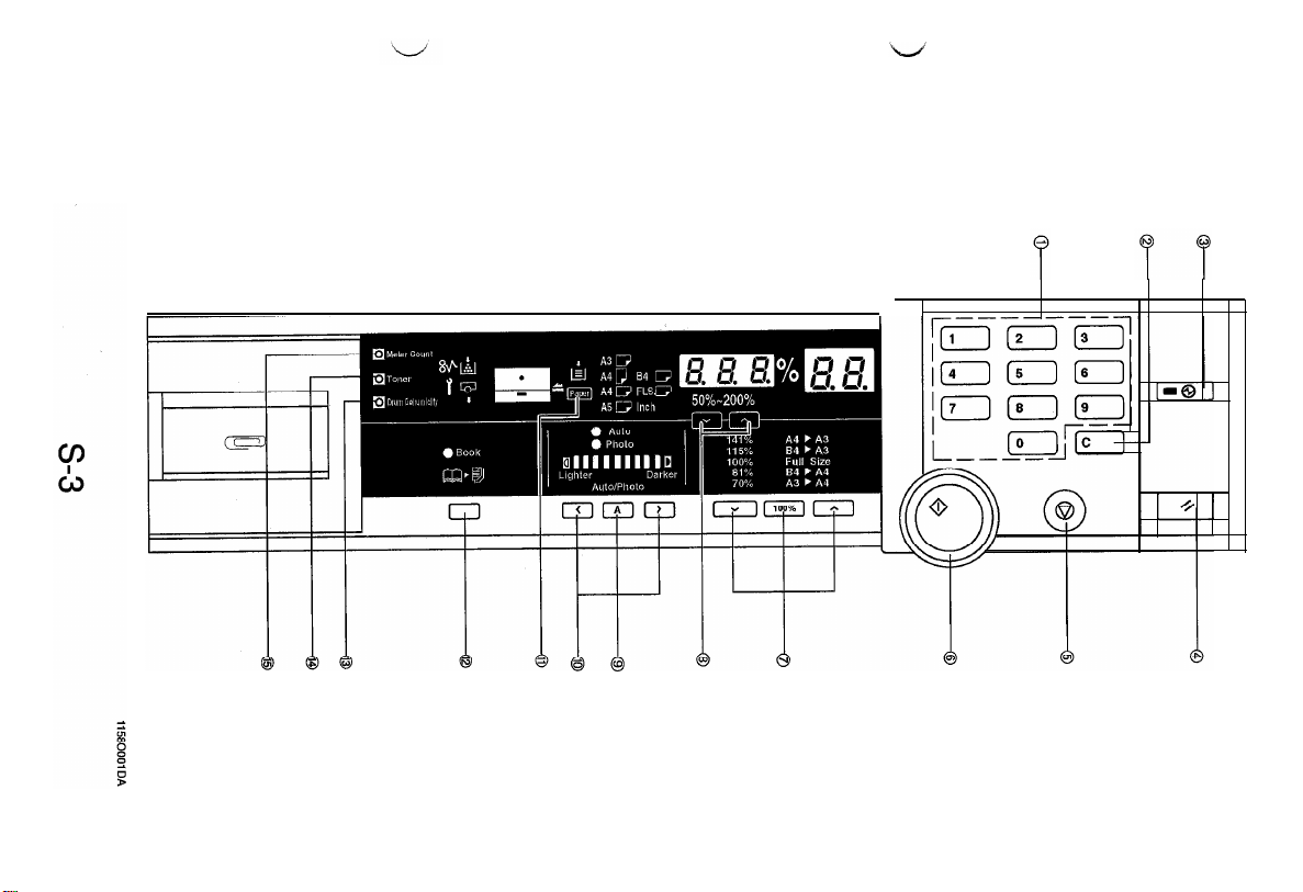
CONTROL PANEL KEYS AND INDICATORS
*
For more details, see the Operators Manual shipped with the copier.
8
0
IO-Keys
l Numeric keypad used for setting the
number of copies to be made, and Tech.
Auto Exposure Mode Key
l Selects either the Auto or Manual
Exposure, or Photo mode.
Rep. mode settings.
($3
Exposure Control Keys
a
0
Clear Key
l
Clear the number-of-copies setting, choice
modes setting.
0
Energy Saver Key
l
Sets the copier into the Energy Saver
mode.
Selects the exposure level.
Paper Select Key
@
l
Selects the paper source.
Book Key
0
l
Selects the Book mode.
1
@
Panel Reset Key
l
Resets the copier to the initial mode.
0
Stop Key
0
Stops a multi-copy cycle or a test
operation.
@
Start Key
0
Starts a multi-copy cycle or a test
operation.
0
Zoom Ratio Select Key
l
Selects a fixed zoom ratio.
@
Zoom Up/Down Keys
l
Changes the zoom ratio manually.
(F*)
(F*)
Drum Dehumidify Key
8
l
Runs a Drum Dehumidify cycle.
Auxiliary Toner Replenishing Key
@
l
Starts an auxiliary toner replenishing se-
quence.
@
Meter Count Key
l
Gives a display of the current copy count.
s-2
Page 5
Page 6
1151SBS0300A
FUNCTIONS OF SWITCHES AND OTHER PARTS ON
1151SBS0301A
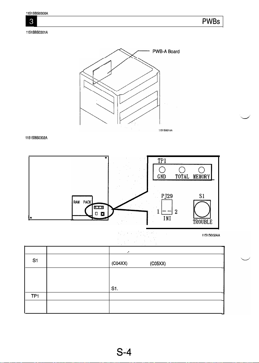
3-1. PWB Location
Tech. Rep. Setting Switches Board
1151SBS0302A
3-2. Tech. Rep. Setting Switches Board
PWBs
Symbol
Sl
PJ2
TPl
TP2
TPl
Name
Trouble Reset Switch
Initialize Points
GND Test Point
Memory Clear Test Point Initializes all data except those counted by the electronic
. .
Resets all malfunctions including Exposure Lamp
(CO4XX)
and fusing
Forcibly resets a misfeed or malfunction that occurred
due to incorrect operation, etc. when it cannot be reset
by opening and closing the Front Door and turning ON
Sl.
Ground terminal used for memory clear.
counters.
Description
(COSXX)
TP3
malfunctions.
TP2
s-4
Page 7
<Clearing Procedures>
l
Initialize Points PJ2
1. Turn OFF the Power Switch.
2. With PJ2 closed, turn ON the Power Switch.
3. In approx. 5 sec., open PJ2.
l
Memory Clear Test Point TP2
I,
Turn OFF the Power Switch.
2. With the circuit across
3. In approx. 5 sec., open the circuit across
-
NOTE
l
If an erratic operation or display occurs, perform the clearing procedures in the order of PJ2 and TP2.
l
When memory clear has been performed, make the necessary settings again.
TPl
and 2 closed, turn ON the Power Switch.
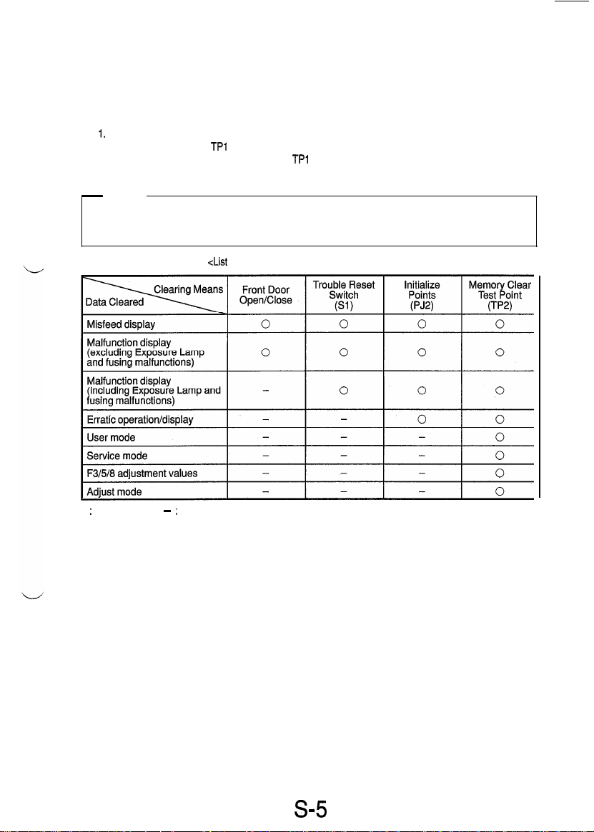
<List
of Data Cleared by Switches and Points>
TPl
and 2.
0 : Cleared
;
Not cleared
-
s5
3
Page 8
1151SBS0400A
m
USER MODE
l
This mode is used to make various settings according to the users needs.
1158SBS0401A
1
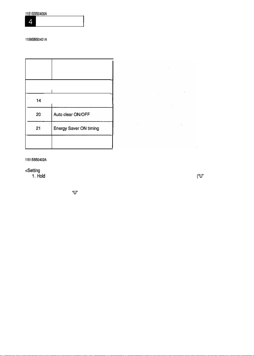
4-1. Functions Available from the User Mode
No.
13
28
1151SBS0402A
Optimum exposure level
Priority manual exposure level
Auto power OFF timing
Function
4-2. User Mode Setting Procedure
<Setting
Procedure>
Hold
down
1.
on the Zoom Ratio Indicator.)
2. From the 1 O-Keys, enter the number assigned to the desired function. (The number entered appears
following the letter
3. Press the Start key.
Display.)
4. Press the Clear key.
5. Make a new setting.
6. Press the Start key to validate the entry of the new setting.
NOTE:
If the setting data entered is outside the specifications, it is not validated and is shown blinking.
<Resetting Procedure>
l
Press the Panel Reset key to return to the Basic screen.
the Panel Reset key
U
for
about 3 seconds to set the copier into the User mode.
on the Zoom Ratio Indicator.)
(Then, the current setting for that particular function appears on the Multi-Copy
(U
appears
S-6
Page 9
1158SSS0403A
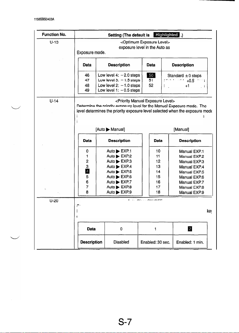
[User Mode]
4-3. User Mode Setting Details
Determine the optimum well as the Manual
Determine the priority exposur
High
level 1:
High
level 2: +l .O steps
+0.5
steps
is switched from the initial Auto to Manual, and when Manual Exposure
initially selected when power is turned ON.
<Auto Clear ON/OFF>
Select whether or not to activate the auto clear (panel reset) function after the
lapse of a given period of time after a copy cycle has been completed or a
on the control panel has been operated.
is
kel
s-7
Page 10

Function No.
u-21
[User Mode]
Setting (The default
<Energy
Select whether or not to set the copier into the Energy Saver mode after the
lapse of a given period of time after a copy cycle has been completed or a key
on the control panel has been operated.
Saver ON Timing>
Cs
m
.)
U-28
Data
1
2
ti
NOTE: Except for 99, the setting data equals the time in minutes.
Select whether or not to enable the auto power OFF function that turns power
off automatically after the lapse of a given period of time after a copy cycle
has been completed or a key on the control panel has been operated.
Data
0
1
2
i
NOTES:
1.
Except
2.
0
cannot be selected for this function if C-4 1 (Auto Power OFF Disabling)
available as one of the Tech. Rep. Choice functions is set to
Description
Enabled: 1 min.
Enabled: 2 min.
Enabled: 15 min.
.
Description
Disabled
Enabled: 1 min.
Enabled: 2 min.
Enabled: 60 min.
for 0 and
99,
Data
Description
.
.
97
98
99
<Auto Power OFF Timing>
Data
Enabled: 97 min.
Enabled: 98 min.
Enabled: 120 min.
Description
.
.
97
*
the setting dafa equals the time in minutes.
98
99
Enabled: 97 min.
Enabled: 98 min.
Enabled: 120 min.
0.
S-8
Page 11

1151SBS0500A
SERVICE MODE
l
This mode is used by the Tech. Rep. to set, check, adjust, and/or program various service functions.
1158SBS0501A
1
5-l. Service Mode Function Tree
Fl
:
Paper passage test
F2 : PC Drum Charge/Image Transfer Coronas
output
F3 : Exposure Lamp voltage adjustment
jX---
Service Mode No. 1
-f$q-
Service Mode No. 2
Service
Mode
F4 : Paper Separator Corona output
F5 : AE Sensor automatic adjustment
F6 : Edge Erase Lamp check
F8 : ATDC Sensor automatic adjustment
F9
:
IU check, optimum exposure adjustment
FA : Scanner/Edge Erase Lamp operation check
-
C-l: Size Counter counting
C-2: Total Counter counting
C-4 : Maintenance Call Reminder ON/OFF
C-5 : PM Counter
c-7 : IU 60K stop
C-l 5 : Toner empty stop
C-20 : Leading edge erase
C-21 : Trailing edge erase
C-23 : Loop length adjustment
C-41 : Auto power OFF disabling
C-90 : ATDC detection level
4
PM Counter and Ports/Options Counter
Paper Size Counter
Malfunction Counter
Parts/Supplies Life Counter
--I
4
Display
1
s-9
1
Service Mode No. 4
Service Mode No. 5
Service Mode No. 6
Service Mode No. 7
Service Mode No. 8
Service Mode No. 0
Page 12

1151SBS0502A
5-2. Entering the Service Mode
<Procedure>
1. Perform the following steps to set the copier into the Service mode.
2. From the 1 O-Keys, press the number corresponding to the service mode no. assigned.
3. Perform the necessary steps for the function selected.
<Leaving the Service Mode>
l
Press the Panel Reset key twice to go back to the Basic screen.
s-10
Page 13

I
1151SBS0503A
5-3. Settings in the Service Mode
1151585050301A
1. Test
l
This function allows the Tech. Rep. to perform various functional tests and adjustments.
<Setting
Procedure>
1. Enter the number assigned to the desired test from the
1
O-Keys. (The number appears on the
Multi-
Copy Display.)
2. Press the Start key to start the test.
3. Press the Stop key to stop the test.
<Test
Copy>
l
A test copy can be made by entering
F3, F5
of the Test No., holding down the Stop key and pressing
the Start key.
<Leaving
the Function>
l
Press the Panel Reset key twice to go back to the Basic screen.
[Service Mode b Test]
Test No.
Fi
A paper passage test is carried out to check for correct sensor operation
without having to wait for the copier to complete warming up. It provides the
following two modes:
1,
Normal mode (The Zoom Ratio Indicator shows On.)
2. Load OFF mode, in which some parts are put in an inactive state (The
Zoom Ratio Indicator shows Off
<Procedure>
1. Using the Zoom Up/Down key, select either one of the two modes.
2. Press the Start key.
Description
<Paper
Passage Test>
.I)
F2
F3
F4
F5
<To
quit>
l
Press the Stop key, or the test stops when paper runs out.
<PC
Drum Charge/Image Transfer Coronas Output>
Do not use this test as it is only for factory adjustment.
<Exposure Lamp Voltage Adjustment>
This test allows the Tech. Rep. to adjust the maximum Exposure Lamp
voltage and the optimum exposure setting in the Manual Exposure mode. (It
runs for 30 sec.)
NOTE
r details, see
DWREASSEMBLY; ADJUSTMENT.
<Paper
Separator Corona Output>
Do not use this test as it is only for factory adjustment.
cAE
Sensor Automatic Adjustment>
This test automatically adjusts the AE Sensor. (It runs for 5 sec.)
NOTE
r details, see
DWREASSEMBLY; ADJUSTMENT
S-11
Page 14

Test No.
F6
F8
F9
FA
[Service Mode b Test]
Description
This test checks whether the Edge Erase Lamp turns ON and OFF properly.
(It runs for one complete copy cycle.)
<Procedure>
l
Press the Start key after the copier has completed warming up. This causes
the lamp to make a checkered
This test automatically adjusts the ATDC Sensor. (It runs for about 5 min.)
NOTE
r details, see
Do not use this test as it is only for factory adiustment.
Do not use this test as it is onlv for
-
Components Energized in the Tests
&canner/Edge Erase Lamp Operation Check>
<Edge Erase Lamp
<ATDC
Sensor Automatic Adjustment>
DIS/REASSEMBL\/: ADJUSTMENT,
cIU
Check, Optimum Exposure
factorv
Check>
oattern.
Adjustment>
adiustment.
-
*Fl
:
Deenergized in the load OFF mode.
*F3/5
:
The Scanner stops at the TRON position.
*F6
:
Turned ON and OFF alternately to make a checkered pattern.
0 : Energized
s-12
-
:
Remain deenergized
Page 15

1151SBS050302A
2. Tech. Rep. Choice
l
This function allows the Tech. Rep. to make various settings and adjustments.
<Setting
Procedure>
1. Press 2 from the 1 O-Keys. (The Zoom Ratio Indicator shows
2. Press the number assigned to the desired Tech. Rep. Choice. (The Zoom Ratio Indicator shows
plus the number of the chosen function.)
3. Press the Start key. (The Multi-Copy Display shows the current setting for the chosen function.)
4. Clear the current setting using the Clear key and enter the new setting from the 1 O-Key Pad.
5. Press the Start key to validate the new setting.
NOTE:
If the setting is illegal, it is not validated and is shown blinking.
<Test Copy>
l
A test copy can be made by entering
pressing the Start key.
v
<Leaving the Function>
e
Press the Panel Reset key twice to go back to the Basic screen.
Choice No.
C-l
C.)
C
of the Tech. Rep. Choice No., holding down the Stop key and
[Service Mode b Tech. Rep. Choice]
Setting (The default is
<Size
Select the size of the paper to be counted by the Size Counter.
Counter Counting>
m
.)
C
c-2
Data
Description
(Metric
areas)
Description
(Inch areas)No
NOTE: See the Count-up Table for details.
Select the conditions (paper size and
Counter count is increased.
Data
Description
NOTE: See the Count-up Table for details.
0
No
count
count
<Total Counter Counting>
I
1 count per 1
copy cycle
0
A3
1lX 17
e-sided
Multiple count-up Multiple count-up
2 3
A3/B4 A3lB4lFLS
14
1lX 17,
-;;;, y
2
1lx
17,
&l/2 x
copying) by which the Total
1
s-13
Page 16

Choke No.
[Service Mode b Tech. Rep. Choice]
Setting (The default is
<Count-up Table>
m
.)
A-4
k
C-5
WchanW
Counting
COPY
CyClEIS
1
122 2 244 1
I I
0: No count 1: 1 count 2: 2 counts 4: 4 counts
<Maintenance Call Reminder ON/OFF>
Select whether to enable or disable the maintenance call reminder.
~(
<PM
Counter>
PM Counter
NOTE:
If this function is set to 2, the copier gives an indication to replace the
IU
and inhibits the initiation of a new copy cycle even if C-4 is set to
0.
s-14
Page 17

Choice No.
c-7
[Service Mode b Tech. Rep. Choice]
Setting (The default is
CIU
Select whether or not to inhibit copying when IU Counter has counted 60K.
60K
m
stop>
.)
C-l 5
c-20
c-21
Data
Description
Default: 0 (inch areas) / 1 (metric areas)
Select whether or not to inhibit copying when a toner-empty condition is
detected.
*I
NOTE: If
I
is set, the copier inhibits copying when it detects a T/C of 2% or
lower.
Varies the width of erase on the leading edge.
~1
NOTE: When the setting is changed, it results in the erase width being changed
by about 3 mm.
Varies the width of erase on the trailing edge.
0
Permits copying.
<Toner Empty Stop>
<Leading Edge Erase>
<Trailing Edge Erase>
1
Inhibits copying.
C-23
>I
NOTE: When the setting is changed, it results in the erase width being changed
by about 3 mm.
Adjust the length of the loop to be formed in paper before the Synchronizing
Rollers.
S-l
5
Page 18

Choice No.
c-41
Eervice Mode b Tech. Rep. Choice1
.
Select whether to enable or disable the setting of “0: Disabled” for “Auto
Power OFF Timing” available from the User mode.
Data
Description
r
Setting (The default is
<Auto Power OFF Disabling>
@
0
Disabled
m
.)
1
Enabled
c-90
Select the ATDC control level (T/C ratio).
cATDC Detection Level>
S-l 6
Page 19

1158SSS050304A
3. PM Counter and Ports/Options Counter
l
This
function shows the counts of the PM Counter
or option is indicated by the corresponding LED of the Misfeed Monitor. The count is shown across
the Zoom Ratio Indicator and Multi-Copy Display.
NOTE: The PM Counter is indicated by the IU Service Life Indicator LED.
I
1
Example) Count: 12345
Multi-C;;;Display 1 / Zoom
(NJ)
and Ports/Options Counter. The particular port
, I
Rayti
Indicator
I
1
Counting System
PM Counter: Count-down type (When the counter has
counted down to zero a - (minus) sign appears in the Zoom
Ratio Indicator and the count is thereafter incremented.
0
Ports/Options Counter: Count-up type
<Setting
Procedure>
1. Select the PM Counter and Ports/Options Counter function.
2.
Each press of the Paper Select key lights up a new LED representing the new counter in the following
order.
<Setting
a PM Counter
1.
Show the count of the PM Counter (IU Service Life Indicator) and clear it.
2. Enter the desired count from the 1 O-Keys.
NOTE
Press the Stop key to undo the clearing command.
3. Press the Start key to validate the new count setting.
<Clearing
a Count?
l
Show the count of the counter to be cleared and press the Clear key.
press the Stop key to undo the clearing command.
Count>
1
If a count is mistakenly cleared,
s-17
Page 20

4. Paper Size Counter
l
This function shows the counts of different sizes of paper.
The paper size is indicated by the Paper Select LED. The count is shown across the Zoom Ratio
Indicator and Multi-Copy Display.
Example) Count: 12345
<Setting
Procedure>
1. Select the Paper Size Counter function.
2.
Each press of the Paper Select key lights up a new LED representing the new counter in the following
order.
[Metric areas]
[inch areas]
Order
1
Description
Legal
Letter
1lx
17
1lX 14
Invoice
<Clearing a Count>
l
Show the count of the counter to be cleared and press the Clear key.
If a count is mistakenly cleared,
press the Stop key to undo the clearing command.
1156SBS050306A
5.
Misfeed Counter
l
This function shows the number of misfeeds that have occurred at different locations in the copier
(count-up type counter). The Monitor Display tells the location of the misfeed by a lit LED. The count
is shown on the Zoom Ratio Indicator and the misfeed code is given on the Multi-Copy Display.
Example) Misfeed location: Manual bypass
Count: 123
<Setting
Procedure>
1. Select the Misfeed Counter function.
Each press of the Paper Select key lights up a new LED representing the new counter in the following
2.
order.
1
Order
1
2
3
4
5
1
Manual bypass
Copier paper take-up/transport
Take-up/transport
Separator
Exit
Description
I
JO
JO
Jl
J2
J3
w
<Clearing a Count>
l
Show the count of the counter to be cleared and press the Clear key. If a count is mistakenly cleared,
press the Stop key to undo the clearing command.
S-18
Page 21

6. Malfunction Counter
l
This function shows the number of malfunctions that have occurred at different locations in the copier
(count-up type counter). The Zoom Ratio Indicator shows the malfunction code, while the Multi-Copy
Display shows the count.
Example) ATDC Sensor malfunction (F30)
<Setting Procedure>
1. Select the Malfunction Counter function.
2. Each press of the Paper Select key shows the count of a new counter in the following order.
NOTE:
Order
1
2
3
4
5
6
7
8
9
IO
11
12
13
14
15
16
<Clearing a Count>
l
Count: 12
The count is given only if it is not
Malfunction Code
000
010
04c
070
400
500
510
520
600
610
620
FIO
F30
El
E2
Arl
Show the count of the counter to be cleared and press the Clear key.
press the Stop key to undo the clearing command.
A Main Drive Motor malfunction
A PC Drive Moter malfunction
A Cooling Fan Motor malfunction
A Toner Replenishing Motor malfunction
An Exposure Lamp malfunction
An abnormally low fusing temperature during warm-up
An abnormally low fusing temperature after completion of warm-up
An abnormally high fusing temperature
A Scanner drive system malfunction
A Lens drive system malfunction
A Mirror drive system malfunction
An AE Sensor malfunction
An ATDC Sensor malfunction
A starter charging failure
An ATDC automatic adjustment/lU fuse blowing failure
Copier watchdog
“0.”
If all counts are
“0, ”
the message
Description
If a count is mistakenly cleared,
“All 0”
is shown.
s-19
Page 22

1158SSS050308A
7. Parts/Supplies Life Counter
l
This function shows the number of copy processes to which different parts or supplies have been
subjected (count-up type). Each count is given as shown below.
Example) NJ Counter
Count: 1234567
___---
_ _ _ _ _ _
Shown alternately
<Setting Procedure>
1. Select the Parts/Supplies Life Counter function”
2. Each press of the Paper Select key shows the count of a new counter in the following order.
<Clearing a Count>
l
Show the count of the counter to be cleared and press the Clear key. If a count is mistakenly cleared,
press the Stop key to undo the clearing command.
NOTE:
The IU Counter cannot be cleared under this function. However, the counts of all counters except the
Fusing Unit Counter under this counter function are cleared when the starter charging sequence is completed.
s-20
Page 23

1158SBS050310A
8.
Display
l
This function is used to check the time it takes the copier to complete different functions and to make
a control panel display test and sensor check.
<Setting
Procedure>
1. Select the Display function.
2. From the 1 O-Keys, enter the number (0, 1,
2,6,
or 7) corresponding to the item to be checked/set.
[Service Mode b Display]
Display Function
d0
dl
d2
d6
d7
The warm-up time is shown on the Zoom Ratio Indicator
(in units of 100 ms).
The first copy time is shown on the Zoom Ratio Indicator
(in units of 100 ms).
The multiple copy time is shown on the Zoom Ratio Indicator
(in units of 100 ms).
All
LEDs
on the control panel are turned ON and OFF
checking operations.
When a misfeed or malfunction occurs, this function is used to make a
sensor
check to isolate the possible faulty spot.
NOTE
r details, see TROUBLESHOOTING.
Setting
<Warm-up time>
<First
copy time>
<Multiple copy time>
<Display test>
<Sensor
check>
(blinking)
for
s-21
Page 24

1151SBS0600A
B
ADJUST MODE
l
The Adjust mode is used to adjust the optical system at the factory. Use this mode only when the RAM
Board (PWB-R) has been replaced and memory clear performed. Whenever PWB-R has been
replaced or memory clear performed, be sure to input the values indicated on the Adjust Mode Label
on the inside of the Front Door.
1151SBS0601A
1
6-1. Functions Available in the Adjust Mode
Function
Code
A0
Al
A2
A3
A4
1151SBS0602A
Lens focal length correction
Lens full size position correction
Mirror full size position correction
Feeding-direction zoom ratio
correction
Full size registration adjustment
Name
Trailing edge erase width
6-2. Entering the Adjust Mode
<Procedure>
1.
Perform the following steps to set the copier into the Service mode.
2. Perform the following steps to set the copier into the Adjust mode.
3. From the 1 O-Keys, press the number corresponding to the adjust mode function to be used.
(The function code appears on the zoom ratio indicator.)
4. Press the Start key. Then, the adjustment data appears on the Multi-Copy Display.
5. Using the Clear key, clear the current adjustment data setting and enter the desired data from the
1 O-Keys.
6. Press the Start key to validate the new data.
NOTE:
If the setting is illegal, it is not validated and is shown blinking.
<Test Copy>
l
A test copy can be made by entering A of the Adjust Mode No., holding down the Stop key and
pressing the Start key.
<Leaving
the Adjust Mode>
l
Press the Panel Reset key twice to go back to the Basic screen.
~
s-22
Page 25

1151
SSS0603A
6-3. Settings in the Adjust Mode
[Service Mode b Adjust Mode]
Adjust Mode
A0
Lens focal length
correction
Al Lens full size
position correction
A2 Mirror full size
position correction
A3 Feeding-direction
zoom ratio
correction
A4 Full size
registration
adjustment
Corrects variations in the Lens focal length (according to the grouping
of the Lenses).
Data 49 50
______ _ _ _ _ _ ____ _ ~ ________________
Description
Corrects the zoom ratio in the crosswise direction by varying the Lens
full size position.
Data 42
______--_-------_~__~~~~~~~~~~~~~
Description
Corrects the optical path length of the Mirror for the Lens focal length.
Data 42
__________-______________________
Description
Correct the zoom ratio in the feeding direction by varying the scan
speed.
Data 42
____________________~~~~~~~~~~~__
Description
Corrects registration between the leading edge of the original and that
of the image in the full size mode by varying the Synchronizing Roller
Short focal length Standard (0)
start timing,
Data 30
____________________--_-_--_-_-__
Description
Setting
51
Long focal length
(-)
steps
steps
-3.2%
. . . .
, . . .
. . . .
. . . .
. . . .
. . . .
. . . .
. . . .
+26
(Reduction
direction) direction)
-1-46
(Reduction
direction) direction)
(Reduction
direction)
-5.6mm
(Smaller (Greater
deviation)
50
+58
steps
50
+l IO steps
50
*o%
50
*Omm
. . . .
. . . .
+86
(Enlargement
. . . .
. . . .
+166
(Enlargement
. . . .
. . . .
(Enlargement
direction)
. . . .
. . . .
deviation)
(+)
steps
steps
+3.2%
+5.6
57
57
58
70
mm
S-23
Page 26

Adjust Mode
A5 Reduction
registration
adjustment
A6 Book-B scan
registration
adjustment
Al 1 Enlargement
registration
adjustment
Al 2 Leading edge
erase width
adjustment
[Service Mode b Adjust Mode]
Setting
Corrects registration between the leading edge of the original and that
of the image in a reduction mode by varying the Synchronizing Roller
start timing.
Data
________------__--------------_--
Description
Corrects the registration between the leading edge of the original and
that of the image in Book-B scan by varying the Synchronizing Roller
start timing.
Data
___-____------------_____________
Description
Corrects registration between the leading edge of the original and that
of the image in an enlargement mode by varying the Synchronizing
Roller start timing.
Data 30
________---__--_----~--~~~~~~~~~~
Description
Corrects the leading edge erase width by varying the Image Erase
Lamp ON timing.
Data 42
________--______--_--~~~~~~~___~~
Description
30
-5.6mm
. . . .
(Smaller
deviation)
30
-5.6 mm
(Smaller
deviation)
-5.6mm .,..
(Smaller
deviation)
-6mm . . . .
($n;tr
. . . .
. . . .
. . . .
. . . .
. . . .
50
&Omm
50
*Omm .,..
50
*Omm ,...
50
*Omm
. . . .
. . . .
. . . .
. . . .
. . . .
. . . .
70
+5.6 mm
(Greater
deviation)
70
+5.6
mm
(Greater
deviation)
70
-1-5.6
mm
(Greater
deviation)
58
+6 mm
(tF$er
Al 3 Trailing edge
erase width
adjustment
Corrects the trailing edge erase width by varying the Image Erase
Lamp ON timing.
Data
________-_--_~r___~-~~~~~~~~~~~~~
Description
40
-7.2 mm
(S$$r
. . . .
. . . .
50
rtOmm
. . . .
. . . .
60
+7.2 mm
(F$ft$r
s-24
Page 27

1151SSS0700A
FUNCTION SETTING REQUIREMENTS AT REPLACEMENT OF PARTS
l
If a part is replaced as part of troubleshooting and other service jobs, some parts require that a Test
operation be run and data values reentered and/or cleared.
PC
Developer Cleaning
Drum
*1
Blade Rollers
Fusing Exposure
Lamp
*2
Memory clear
Initialize
Job program
User mode
-
Tech. Rep. Choice
Test F3
Test F5
Test F8
PM Counter
Clearing Parts/
42
Supplies Life
Counter PC
ii
8
.-
Clearing Parts/
2
Supplies Life
r%
Counter St
Clearing Parts/
Supplies Life
Counter
Cb
Clearing Parts/
Supplies Life
Counter Fu
-
Adjust mode
*1
: Including the replacement of the ATDC Sensor
*2
:
Including the cleaning of Lamp Regulator and optical system.
0
0
0
0
: Required
s-25
Page 28

MINOLTA
Copyright
1996
MNOLTA
Printed in Japan
CO., LTD
MINOLTA CO,,
LTD,
1158-7997-1297110150
Printed in Japan
 Loading...