

Page 1
EPlO52
-
GENERAL,
MECHANICA
ELECT
MINOLTA
RICA
Page 2
1158SBGOOOBA
CONTENTS
SPECIFICATIONS
1.
PRECAUTIONS FOR INSTALLATION
2.
PRECAUTIONS FOR USE
3.
HANDLING OF THE CONSUMABLES
4.
5.
SYSTEM OPTION
1158SBMOOOBA
1
MECHANICAL/ELECTRICAL
CROSS-SECTIONAL VIEW
1.
COPY PROCESS
2.
DRIVE SYSTEM
3.
SEQUENTIAL EXPLANATION
4.
PC DRUM
5.
IMAGINGUNIT .............................................
6.
6-l. Imaging Unit Drive
6-2. Toner Recycling
6-3. I/U Fuse F4
DEVELOPMENT
7-l. ATDC Sensor
7-2. Magnet Roller
7-3. Developing Bias
7-4. Doctor Blade
7-5. Magnet Roller Lower Filter
CLEANING UNIT
8-1. Cleaning Unit
8-2. Cleaning Bias
TONER HOPPER
9-l.
9-2.
9-3.
9-4.
9-5.
9-6.
.................................................
Toner Hopper Locking/Unlocking
Toner Replenishing
Shutter
Toner Hopper Home Position Detection
Toner Bottle Vibration
Toner Replenishing Control
..........................................
...................................
..........................................
...........................................
............................................
......................................
........................................
............................................
............................................
..........................................
..........................................
........................................
...........................................
...........................................
..........................................
..........................................
...........................................
.....................................
..............................................
...................................
.........................
.........................
1
..................................
................................
...............................
..........................
....................
..............................
G-l
G-4
G-5
G-6
G-7
M-l
M-2
M-4
M-5
M-10
M-11
M-12
M-13
M-13
M-l 4
M-15
M-17
M-18
M-19
M-19
M-20
M-20
M-21
M-22
M-22
M-22
..M-2 3
M-23
M-24
M-25
i
Page 3
CONTENTS
10.
DRUM CHARGING
11. IMAGE ERASE LAMP
12. OPTICAL SECTION
12-1.
Exposure Lamp LA1
12-2.
AESensor............................................M-3
Lamp Reflectors
12-3.
12-4.
Aperture Plates
12-5.
1
st/2nd
12-6.
4th Mirror Movement
12-7.
Lens Movement
13. MAIN
14. IMAGE TRANSFER AND PAPER SEPARATION
15. PAPER SEPARATOR FINGERS
16. PAPER TAKE-UP/FEED SECTION
17. VERTICAL PAPER TRANSPORT . . . . . . . . . . . . n . m , . m . . . . . . . , . . , M-52
ERASE LAMP
16-1.
Edge Guide and Trailing Edge Stop
Drawer Positioning
16-2.
16-3.
Paper Lifting Plate
Drawer-in-Position Detection
16-4.
16-5.
Universal Tray Paper Size Detection
16-6.
Paper Empty Detection
16-7.
Paper Separating Mechanism
16-8.
Paper Take-Up Roll
16-9.
Paper Take-Up Retry Control
..........................................
.......................................
.........................................
...................................
.......................................
.......................................
Scanner Movement
.......................................
.........................................
....................................
.....................................
....................................
.............................
...................................
................
..............................
............................
......................
............................
.....................
.................................
...........................
............................
M-26
M-27
M-30
M-31
M-33
M-33
M-34
M-36
M-37
M-38
M-39
M-41
M-43
M-44
M-45
M-45
M-46
M-47
M-48
M-49
M-50
M-51
2
-
18. SYNCHRONIZING ROLLERS
18-l. Upper Synchronizing Roller Positioning
18-2. Paper Dust Remover
18-3. Synchronizing Roller Drive
19. PAPER TRANSPORT
20. FUSING UNIT . . . . . . . . . . . . . . . . . . . . . . . . . . . . . . . . . . . , . . . . . . . . . . M-57
20-l.
Fusing Temperature Control
20-2.
Fusing Rollers Pressure Mechanism
20-3
Oil Roller/Cleaning Roller
21
m
EXIT
UNIT
.................................................
21-1,
Upper/Lower Separator Fingers
21-2,
Paper Exit Sensor
.......................................
................................
...................
...................................
..............................
.............................
.....................
...............................
.........................
.....................................
M-53
M-54
M-54
M-55
M-56
M-58
M-59
M-59
M-60
M-60
M-61
ii
-
Page 4

CONTENTS
22. DEHUMIDIFYING SWITCH (OPTION)
23. MULTI BYPASS TABLE MB-4 (OPTION)
23-1. Paper Take-Up Mechanism
23-2. Paper Separating Mechanism
23-3. Paper Empty Detection
24. COOLING FAN
25. OPTICAL SECTION COOLING FAN
26. MEMORY BACKUP
.............................................
.........................................
.................................
.........................
.............................
...........................
...........................
.......................
M-62
M-63
M-64
M-66
M-67
M-68
M-69
M-70
Page 5
/-MEMO
Page 6

GENERAL
Page 7
1158SBGDlOOA
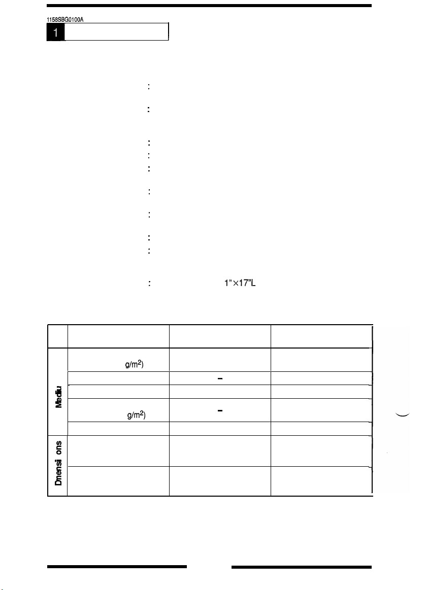
SPECIFICATIONS
)
TYPE
PHOTOCONDUCTOR :
COPYING SYSTEM
PAPER FEEDING
SYSTEM
EXPOSURE SYSTEM
DEVELOPING SYSTEM
CHARGING SYSTEM
IMAGE TRANSFER
SYSTEM
PAPER SEPARATING
SYSTEM
FUSING SYSTEM
PAPER DISCHARGING
SYSTEM
MAXIMUM ORIGINAL
SIZE
COPY MEDIUM
Plain paper
,_
B
z
E
=
(60 to 90
Translucent paper
.
Transparencies
(91 to 157
Recycled paper
g/m2)
Thick paper
g/m2)
Desktop (with Stationary Platen)
Organic Photoconductor
Electrostatic Dry Powdered Image Transfer to Plain
:
Paper
2-Way Feeding Paper Drawer: Universal Tray
:
Manual Bypass Table
Mirror Scanning, Slit Exposure
:
Minolta New Micro-Toning System
:
Comb Electrode DC Negative Corona with Scorotron
:
System
Visible Image Transfer by means of a Single-Wire DC
:
Negative Corona with Corotron System
Single-Wire AC Corona with Corotron System, plus
:
Paper Separator Finger
:
Heat Roller
:
Charge Neutralizing Brush
Metric-A3L; Inch-l
:
(Automatic feeding) (Single-sheet feeding)
1
x
17L
Paper Drawer
0 0
-
-
0 0
(250 sheets of paper)
(L: Lengthwise)
Manual Bypass
0
0
0
:
*-
2
E
I_
0
0: Permissible
(Width Maximum x Length)
(Width x Length)
Minimum
X: Not permissible
297x432 mm
140x182mm
G-l
297x432 mm
100x140 mm
Page 8
MULTIPLE COPIES
WARMING-UP TIME
FIRST COPY TIME
:
1to99
:
30 sec.
or less
power voltage
:
A4C
or 8-l
(in
Full size Mode using 1 st Drawer)
with
room temperature of
/2
x 11 C: 7.2 sec. or less
20C
and rated
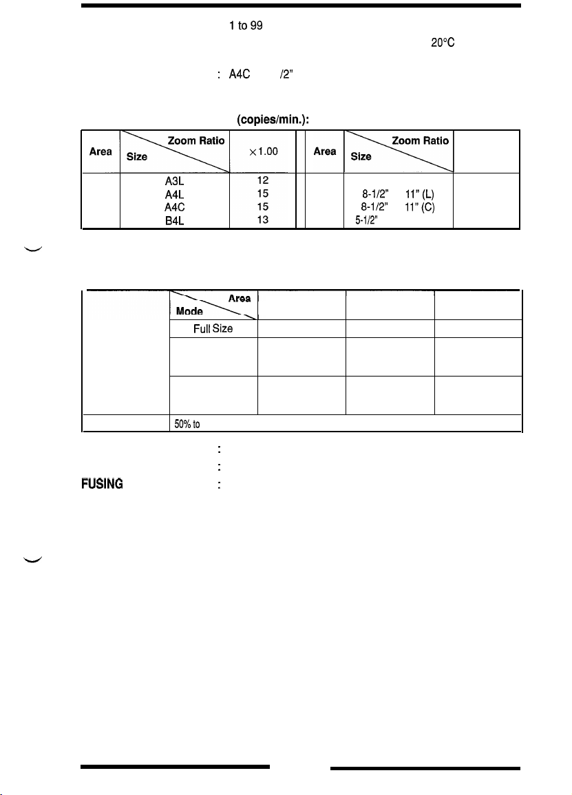
CONTINUOUS COPY SPEED
A3L
Metric
w
L: Lengthwise; C: Crosswise
ZOOM RATIOS
A4L
A4C
B4L
Full Size
Fixed
Variable
LENS
EXPOSURE LAMP
Reduction
Enlargement
50%to
FUSING
TEMPERATURE
(copies/min.):
Europe (Metric) Taiwan (Metric)
200% (in 1% increments)
:
Through Lens (F = 8.0, f = 180 mm)
:
Halogen Frost Tube Lamp
:
195C
Fed from Drawer
Inch
100% 100%
81% 81%
70%
50% 50%
115% 122%
141% 141%
200% 200%
11" x 17" (L)
8-l/2"
x
8-l/2"
5-l/2"
11"(L)
x
11"(C)
x 8-1/2"(L) 15
70%
x1.00
11
15
15
Inch
100%
78%
64%
50%
121%
129%
200%
G-2
Page 9
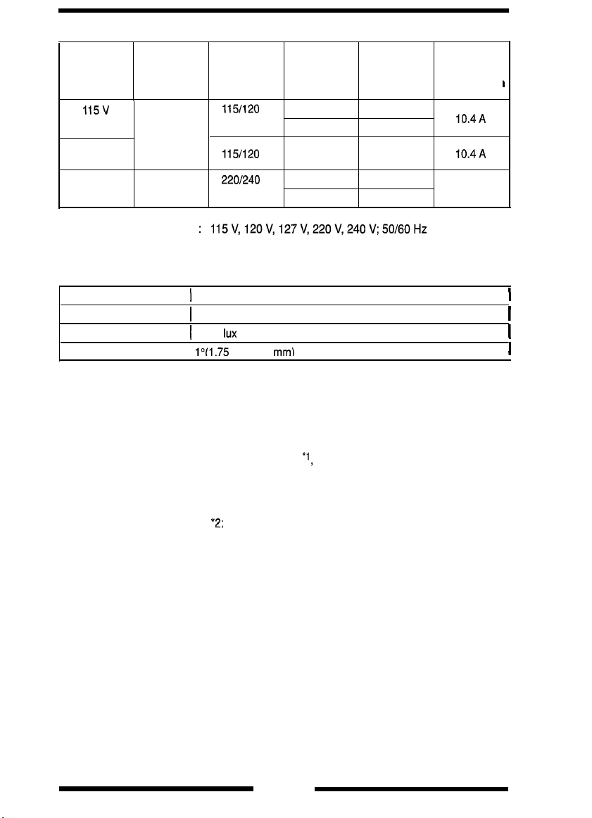
POWER/CURRENT CONSUMPTION (Copier Only)
Exposure
Voltage
115V
120v
127V
220 v
240 V
POWER
REQUIREMENTS
ENVIRONMENTAL CONDITIONS
Temperature
Humidity
Ambient Illumination
Levelness
Lamp
(Rating)
80 V
225 W
160V
240 W
Fusing
Heater
Lamp
(Rating)
115/120
900 w
115/120
900 w
220/240
900 w
:
115V,120V,127V,220V,240V;50/60Hz
)
10 to 35C with a fluctuation of 10C or less per hour
1
15 to 85% RH with a fluctuation of 10% RH or less per hour
1
3,000
lux
or less
I lY1.75 mm/l 00
Max. Power
Consumption
v
1180
1220
V
1290
V 1195
1270
mm)
In Standby Current
W
w
w
w
W
935 w
965 W
1070 w
930 w
1060 W
Max.
Consumption
10.4A
10.4A
5.6 A
I
I
I
I
I
DIMENSIONS
(Copier Only)
WEIGHT
STANDARD
ACCESSORIES
Width . . . . 610
Depth . . . .
mm
632.5 mm
Height . . . 401 mm (including Original Cover)
51 kg (excluding the Manual Bypass Table, starter,
toner, and paper)
Operators Manual
*I,
Setting-up Instructions, Starter**, Copy
Tray, Manual Bypass Table, Auxiliary Cap
1: Except Europe and Taiwan
*2;
Europe only
G-3
Page 10
1151Si3G0200A
PRECAUTIONS FOR INSTALLATION
1
I InstallatCon
Site
To ensure safety and utmost performance of the copier, the copier should NOT be
used in a place:
0
Where it will be subject to extremely high or low temperature or humidity.
0
Which is exposed to direct sunlight.
0
Which is in the direct air stream of an air conditioner, heater or ventilator.
0
Which puts the operator in the direct stream of exhaust from the copier.
0
Which has poor ventilation.
0
Where ammonia gas might be generated.
0
Which does not have a stable, level floor.
0
Where it will be subject to sudden fluctuations in either temperature or humidity.
If a cold room is quickly heated, condensation forms inside the copier, resulting in
blank spots in the copy.
0
Which is near any kind of heating device.
0
Where it may be splashed with water.
0
Which is dirty or where it will receive undue vibration.
0
Which is near volatile flammables or curtains.
H
Power Source
Use an outlet with a capacity of
115/l
20/l
27V, 13.2A
or more, or
200/220/24OV,
8.1 A
or more.
0
If any other electrical equipment is
sourced
from the same power outlet, make sure
that the capacity of the outlet is not exceeded.
0
Use a power source with little voltage fluctuation
0
Never connect by means of a multiple socket any other appliances or machines
to the outlet being used for the copier.
0
Make the following checks at frequent intervals:
l
Is the power plug abnormally hot?
l
Are there any cracks or scrapes in the cord?
l
Has the power plug been inserted fully into the outlet?
l
Does something, including the copier itself, ride on the power cord?
0
Ensure that the copier does not ride on the power cord or communications cable
of other electrical equipment, and that it does not become wedged into or underneath the mechanism.
1
Grounding
To prevent receiving electrical shocks in the case of electrical leakage, always ground
the copier.
l
Connect the grounding wire to:
l
The ground terminal of the outlet.
l
A grounding contact which complies with the local electrical standards.
0
Never connect the grounding wire to agas pipe, the grounding wire for a telephone,
or a water pipe.
G-4
Page 11
1151 SSG0300A
PRECAUTIONS FOR USE
To ensure that the copier is used in an optimum condition, observe the following precautions.
0
Never place a heavy object on the copier or subject the copier to shocks.
0
Insert the power plug all the way into the outlet.
@
Do not attempt to remove any panel or cover which is secured while the copier is
making copies.
0
Do not turn OFF the Power Switch while the copier is making copies.
0
Provide good ventilation when making a large number of copies continuously.
0
Never use flammable sprays near the copier.
0
If the copier becomes inordinately hot or produces abnormal noise, turn it OFF and
unplug it.
0
Do not turn ON the Power Switch at the same time when you plug the power cord
into the outlet.
0
When unplugging the power cord, do not pull on the cord; hold the plug and pull
it out.
0
Do not bring any magnetized object near the copier.
l
Do not place a vase or vessel containing water on the copier.
0
Be sure to turn OFF the Power Switch at the end of the workday or upon power
failure.
0
Use care not to drop paper clips, staples, or other small pieces of metal into the
copier.
n
Operating Environment
The operating environmental requirements of the copier are as follows,
l
Temperature: 10C to 30C with a fluctuation of
l
Humidity: 15% to 85% RH with a fluctuation of
10C
10%
RH per hour
per hour
H
Power Requirements
The power source voltage requirements are as follows.
l
Voltage Fluctuation:
AC1
15/l
20/l
27/220/24OV
f
10% (Copying performance assured)
-15% (Paper feeding performance assured)
l
Frequency Fluctuation:
50/60
Hz
-+0.3%
G-5
Page 12

1151SBG0400A
HANDLING OF THE CONSUMABLES
Before using any consumables, always read the label on its container carefully.
0
Use the right toner. The applicable copier model name is indicated on the Toner
Bottle.
1
l Paper is apt to be easily damaged by dampness. To prevent absorption of
moisture, store paper, which has been removed from its wrapper but not loaded
into the Drawer, in a sealed plastic bag in a cool, dark place.
0
Keep consumables out of the reach of children.
0
Do not touch the PC Drum with bare hands.
0
Store the paper, toner, and other consumables in a place free from direct sunlight
and away from any heating apparatus.
0
The same sized paper is of two kinds, short grain and long grain. Short grain paper
should only be fed through the copier crosswise, long grain paper should only be
fed lengthwise.
0
If your hands become soiled with toner, wash them with soap and water
immediately.
0
Do not throw away any used consumables (PC Drum, starter, toner, etc.). They are
to be collected.
NOTE
Do not burn, bury in the ground, or throw into the water any
consumables (PC Drum, starter, toner, etc.).
G-6
Page 13
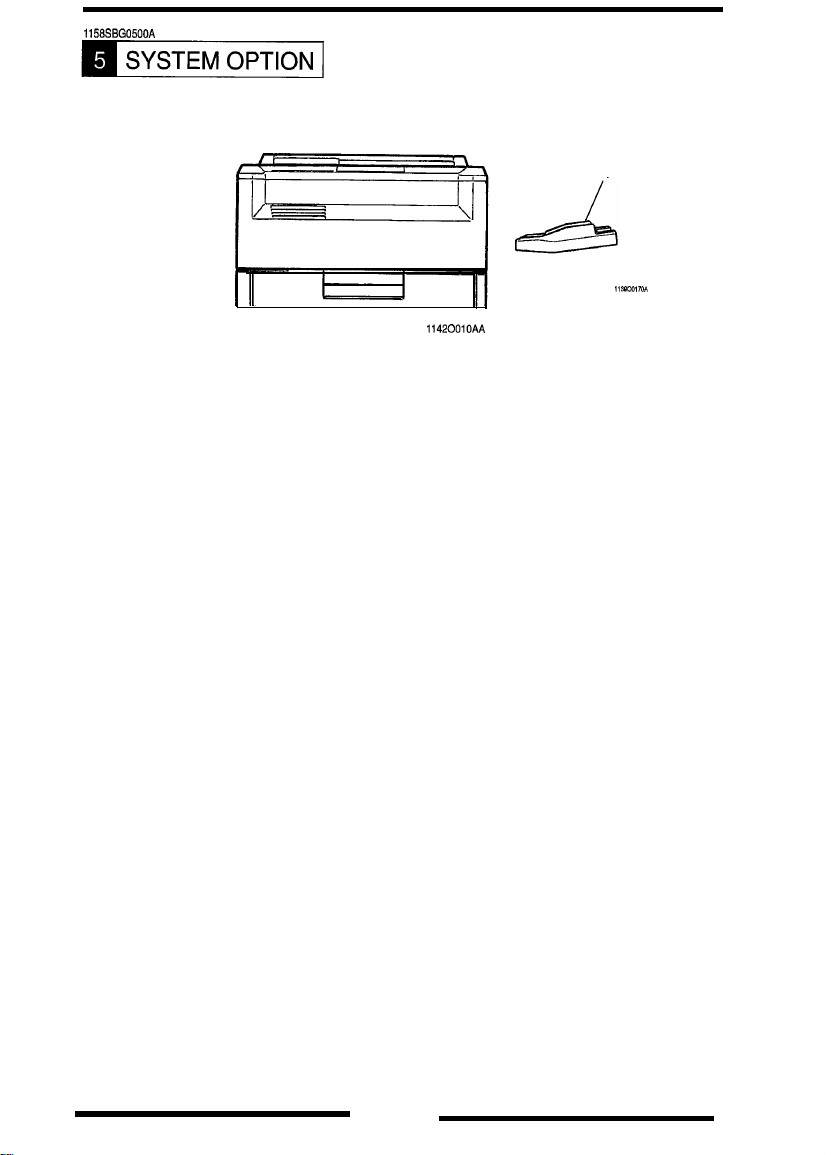
1158SBG0500A
11420010AA
1. Multi
Bypass
Table MB-4
G-7
Page 14

MECHANICAL/
ELECTRICAL
Page 15
1158SBMOlOOA
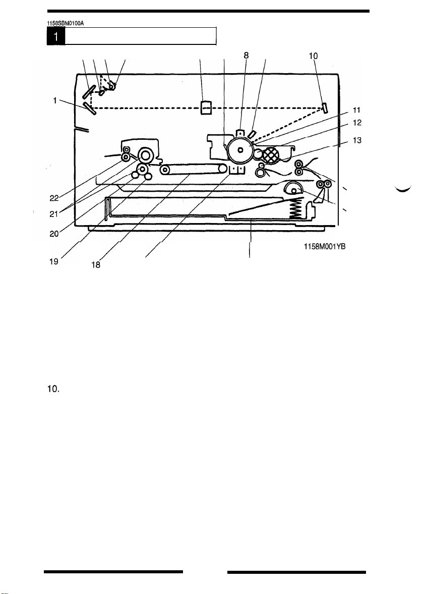
CROSS-SECTIONAL
234 5
VIEW
6 7 6
1
9
10
L
'
14
15
,,/
/
16,
1.
3rd Mirror
2nd Mirror
2.
3.
1st Mirror
4.
Exposure Lamp LA1
5.
Lamp Reflector
6.
Lens
7.
Cleaning Blade
PC Drum Charge Corona
8.
9.
Image Erase Lamp LA3
4th Mirror
10.
PC Drum
11.
12.
Sleeve/Magnet Roller
17
/
13.
14.
15.
16.
17.
I
16
Synchronizing Roller
Transport Roller
Paper Take-Up Roll
Drawer
Image Transfer/Paper Separa-
1158MOOlYB
tor Coronas
18.
Suction Unit
19.
Cleaning Roller
20.
Oil Roller
21.
Upper/Lower Fusing Roller
22.
Paper Exit Roller
M-l
Page 16
1158SBM0200A
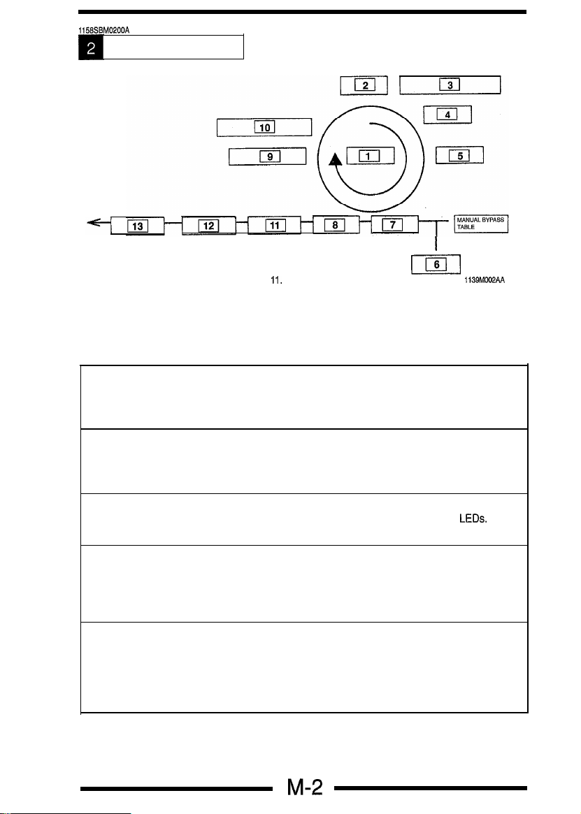
COPY PROCESS
1.
PC DRUM
2.
DRUM CHARGING
3.
IMAGE ERASE
4. EXPOSURE
5.
DEVELOPING
6.
PAPER FEEDING
7.
IMAGE TRANSFER
1
6.
PAPER SEPARATION
9.
CLEANING
10.
MAIN ERASE
Il.
TRANSPORT
12.
FUSING
13.
PAPER EXIT
I
1139M002AA
1. PC Drum
The PC Drum is an aluminum cylinder coated with a photosensitive semiconductor.
It is used as the medium on which a visible developed image of the original is formed.
(For more details, see p. M-l 0.)
2. Drum Charging
The PC Drum Charge Corona Unit is equipped with a Comb Electrode and a Scorotron Grid to
deposit a uniform negative charge across the entire surface of the PC Drum.
(For more details, see p. M-26.)
3. Image Erase
Any areas of charge which are not to be developed are neutralized by lighting up
(For more details, see p. M-27.)
LEDs.
4. Exposure
Light from the Exposure Lamp reflected off the original is guided to the surface of the PC
Drum and reduces the level of the negative charges, thereby forming an electrostatic latent
image.
(For more details, see p. M-30.)
5.
Developing
Toner positively charged in the Developer Mixing Chamber is attracted onto the electrostatic
latent image changing it to a visible, developed image. A DC negative bias voltage is applied
to the Sleeve/Magnet Roller to prevent toner from being attracted onto those areas of the PC
Drum which correspond to the background areas of the original.
(For more details, see p. M-l 4.)
Page 17
6. Paper Feeding
Paper is fed either automatically from the 1 st or 2nd Drawer, or manually via the Manual
Bypass Table. The Drawer has fingers that function to separate the top sheet of paper from
the rest at take-up.
(For more details, see p. M-43.)
7. Image Transfer
The single-wire Image Transfer Corona Unit applies a DC negative corona emission to the
underside of the paper, thereby attracting toner onto the surface of the paper.
(For more details, see p. M-30.)
8. Paper Separation
The single-wire Paper Separator Corona Unit applies an AC corona emission to the underside
of the paper to neutralize the paper. In addition, mechanical paper separation is provided by
the two PC Drum Paper Separator Fingers fitted to the Imaging Unit.
(For more details, see p. M-30)
9. Cleaning
Residual toner on the surface of the PC Drum is scraped off by the Cleaning Blade.
(For more details, see p. M-20.)
10. Main Erase
Light from the Main Erase Lamp neutralizes any surface potential remaining on the surface of
the PC Drum after cleaning.
(For more details, see p. M-38.)
11. Transport
The paper is fed to the Fusing Unit by the Suction Belts.
(For more details, see p. M-56.)
12. Fusing
The developed image is permanently fused to the paper by a combination of heat and
pressure applied by the
(For more details, see p. M-57.)
Upper
and Lower Fusing
Rdlers.
13. Paper Exit
After the fusing process the paper is fed out by the Paper Exit Roller onto the Copy Tray.
(For more details, see p. M-60.)
M-3
Page 18
1158SBM0300A
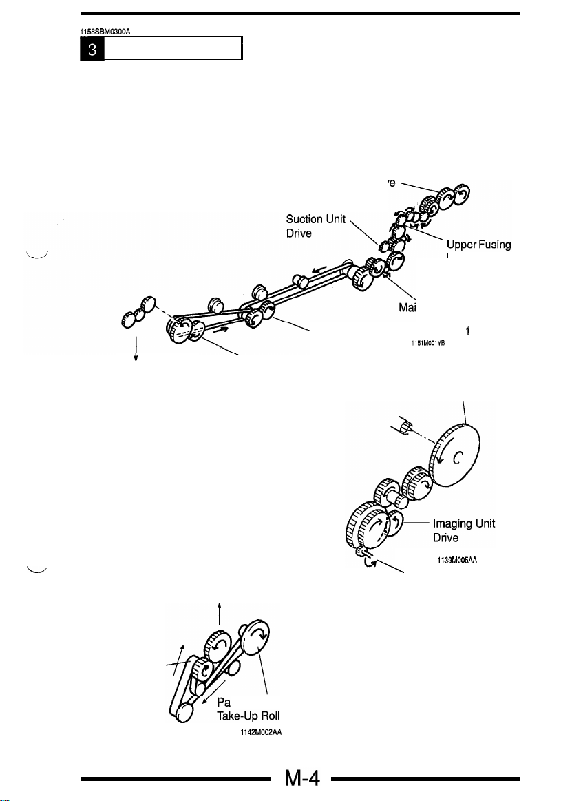
DRIVE SYSTEM
1
This copier is equipped with two main drive motors, PC Drive Motor Ml that drives
the upper half of the copier (Imaging Unit) and Main Drive Motor M2 which gives
drive for the lower half of the copier (paper take-up/feeding and transport
mechanism and Fusing Unit). Each has its own drive transmitting gears and timing
belts as illustrated below.
Drive Train for Lower Half of Copier
Paper Exit Roller Driv
Roller Drive
n Drive Motor M2
+
Coupled to Paper
Take-Up Unit
Synchronizing Roller Clutch CL
Paper Transport
Clutch CL 2
Drive Train for Upper
Half of Copier
1151MOOlVB
Drive Train for
w
Paper Take-Up Unit
Coupled to Copier Gear
Vertical
Transport Roller
per Drawer Paper
PC Drive Motor Ml
1
PC Drum Drive
1139MOO5AA
1142M002AA
Page 19
1158SSM0400A
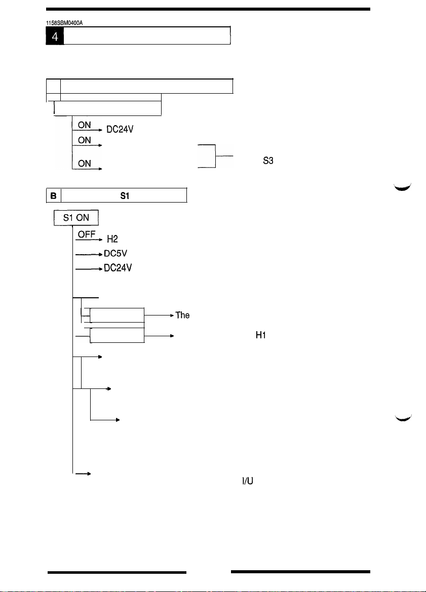
SEQUENTIAL EXPLANATION
)
*Numbers given in rectangles0
A
The power cord is plugged into the outlet.
)
Power cord is plugged in.
DC24V
for Drum heating (PU2)
Drum Dehumidifying
Heater H2
Paper Dehumidifying
Heater H3
6 Power Switch Sl is turned ON.
z
H2
ON
-
DC5V
(PWB-C)
ON
-
DC24V
(PU2)
ON
------ Control panel
ON
l
The Cooling Fan turns at full speed.
Approx. 3
Approx. 0.5
ON
c
Scanner Reference Position Sensor PC81
If the Scanner
M5 is energized to move the Scanner to the home position.
ON
+
Lens Reference Position Sensor PC90
*If the Lens is not at the home position, Lens Motor M6 is
energized to move the Lens to the home position.
ON
c
Mirror Reference Position Sensor PC86
*If the 4th Mirror is not at the home position, Mirror Motor M7
is energized to move the Mirror to the home position.
in the following flowchart are timer values in sec.
ON
~-The
ON
h
Fusing Heater Lamp Hi
is not at the home position, Scanner Motor
Only when Serviceman
Switch 53 is ON
Cooling Fan turns at half speed.
__.
Starter setup and ATDC Sensor automatic adjustment
*Only when the Imaging Unit is new.
when the starter setup sequence is completed normally.
I/U
Fuse F4 blows
M-5
Page 20

C
The Fusing Unit temperature reaches 205%.
1 Fusincl
Thermistor THI detects
L-
oNoFFFusing Heater Lamp HI
*The Fusing Unit temperature control is started.
2OCPC.
1
M-6
Page 21
D
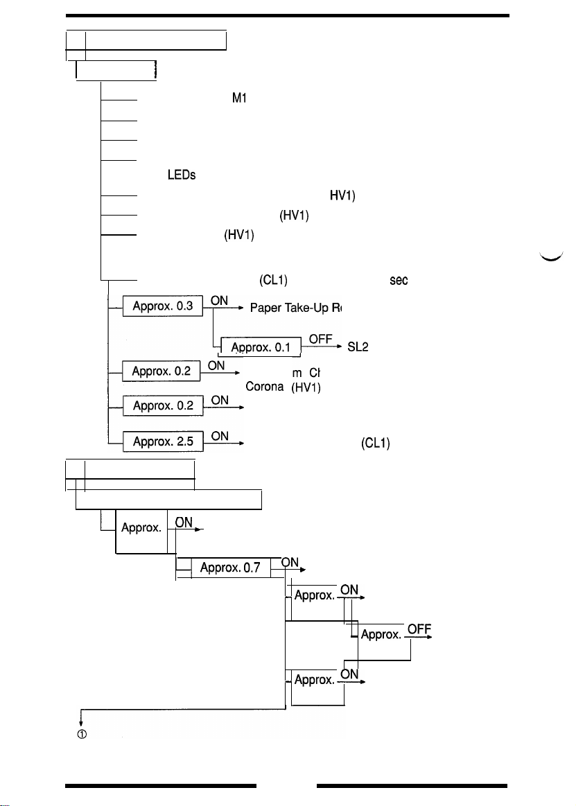
The Start Key is pressed.
1
Start Key ON
ON
ON
ON
ON
ON
ON
ON
ON
1
PC Drive Motor Ml
Main Erase Lamp LA2
Main Drive Motor M2
Image Erase Lamp LA3
*All
LEDs
are turned ON.
Developing Bias (High Voltage Unit HVI)
Paper Separator Corona (HVI)
Cleaning Bias
*Some models have no Bias Seal installed depending
on their marketing areas.
Synchronizing Roller (CLI) *For approx 0.2
(HVl)
Paper Take-Up Roll (Solenoid SL2)
set
only
t=LL=b
psi=-+
E
Paper is taken up.
Paper Take-Up Solenoid SL2 ON
APProx.ON e Drawer Paper Take-Up Sensor PC55
0.4
APProx. 0.7
SL2
PC Drum Charge Corona/Image Transfer
Corona
(iv,)
Transport Roller (Paper Transport Clutch CL2)
Synchronizing Roller
ON c
Transport Roller Sensor PC51
- APProx. 3
0.5
- APProx. a
0.2
(CLl)
Paper Leading Edge
Detecting Sensor PC54
- APProx. z
0.2
Exposure Lamp LA1
Paper
Transport
Clutch CL2
M-7
Page 22
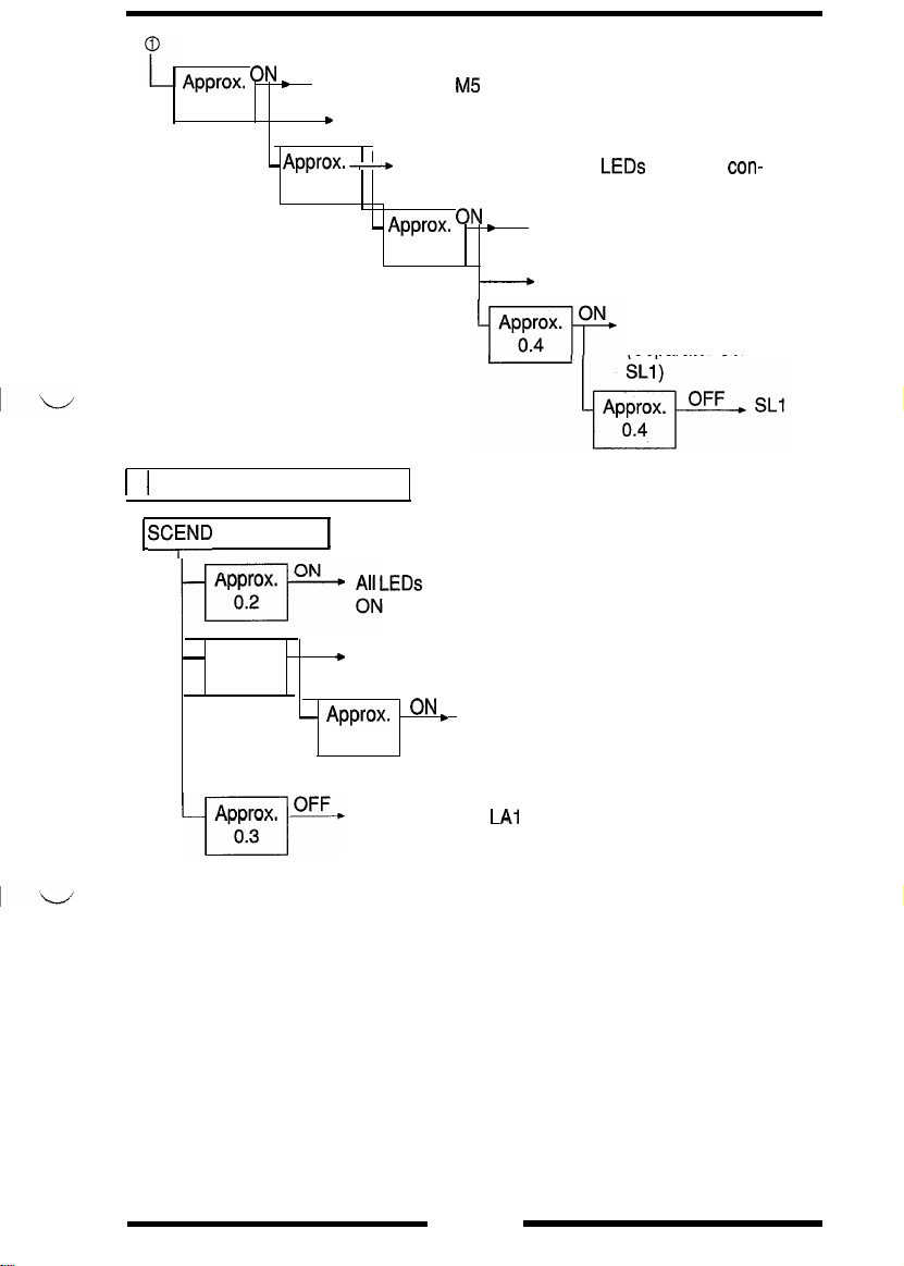
APProx. ON c
0.6
Scanner Motor
OFF
c
Scanner Reference Position Sensor PC81
M5
- APProx. -
0.3
1
F 1 A scan motion is completed.
1 SCFND
signal: LOW
-
Approx.
0.3
- APProx.ON t Scanner Reference Position Sensor PC81
*For A4 crosswise, x 1 .OOO
Image Erase Lamp LA3
_
Approx. ON .
1
LEDs
*
Scanner starts return motion.
0.6
LEDs
ON/OFF
trol is started.
Synchronizing Roller Clutch
-
ON
CL1
CL2
Separator Fingers
(Separator Solenoid
0.2
of Unexposed Areas/Edge Erase Lamp LA3
con-
7-p
Exposure Lamp
M-8
LA1
Page 23
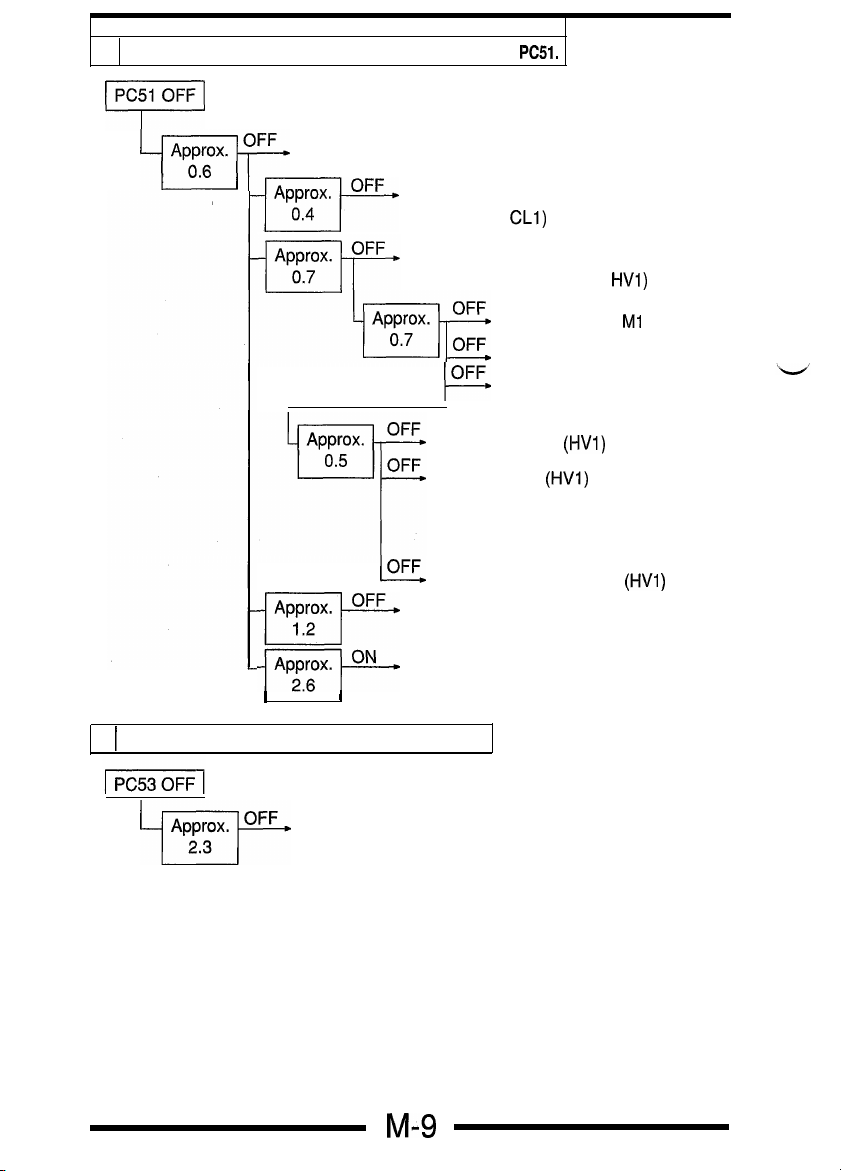
G
The last paper moves past Transport Roller Sensor
PC51 OFF
7
)
0.6
T
1
Paper Leading Edge Detecting Sensor PC54
Synchronizing Roller (Synchronizing
1-p
Roller Clutch
PC Drum Charge Corona/Image Transfer
Corona (High Voltage Unit HVI)
OFF
I-
PC51.
CLl)
PC Drive Motor Ml
Main Erase Lamp LA2
Unexposed Areas/Edge
Erase Lamp LA3
Developing Bias
Cleaning Bias
*Some models have no Bias Seal
installed depending on their
marketing areas.
OFF
I-
Paper Separator Corona
iAl;p:oxp
~=Gfp_
I
H 1 The paper moves past Paper Exit Sensor PC53.
Lpqy
I
Main Drive Motor M2
Transport Roller (CL2)
Paper Exit Sensor PC53
(HVl)
(HVl)
(HVI
)
M-9
Page 24
1151SBM0500A
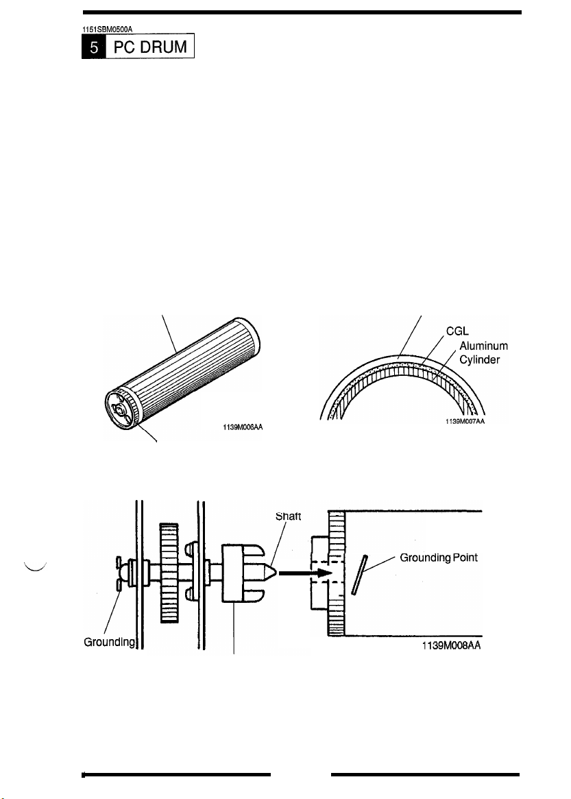
~7ciii-l
The photoconductive drum used in this copier is the organic photoconductor (OPC)
type. The drum is made up of two distinct, semiconductive materials on an aluminum alloy base. The outer of the two layers is called the Charge Transport Layer
(CTL), while the inner layer is called the Charge Generating Layer (CGL).
The PC Drum has its grounding point inside at its rear end. When the Imaging Unit
is installed in the copier, the shaft on which the PC Drum Drive Coupling Gear is
mounted contacts this grounding point.
Handling Precautions
This photoconductor exhibits greatest light fatigue after being exposed to light over
an extended period of time. It must therefore be protected from light by a clean, soft
cloth whenever the Imaging Unit has been removed from the copier. Further, use
utmost care when handling the PC Drum to prevent it from being contaminated.
PC Drum Cross-Sectional View
Plate
PC Drum
.
Gear
_
CTL
1139M006AA
Grounding Point
r
!iiiL--
1139MCWAA
PC Drum Drive Coupling Gear
r
M-10
Page 25
1139SBhAO6OOA
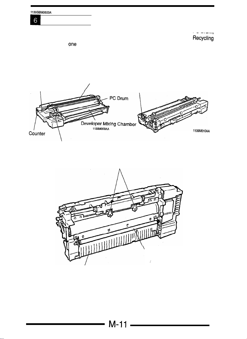
IMAGING UNIT
This copier is equipped with an Imaging Unit, or IU, which integrates a PC Drum
PC Drum Charge Corona, Developing Unit, Cleaning Unit, and Toner Recyclini
mechanism into
Roller which facilitates clearing of a paper misfeed.
one
assembly. The Unit also includes the Upper Synchronizing
Corona Unit Cleaning/PC Drum
Lever
Charge Corona
Toner Supply Port
Paper Separator Fingers
Coupled to Gear
in Copier
1139MOlOAA
Paper Guide Plate
Upper Synchronizing Roller
t
1139MOllAA
Page 26
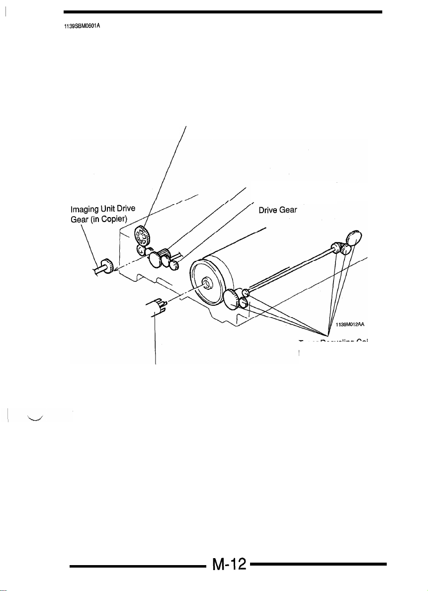
1139SBM0601A
6-1. Imaging Unit Drive
Drive for the Imaging Unit is transmitted by one of the gears on the Unit.
This particular gear is in mesh with the Imaging Unit Drive Gear in the copier.
Developer Mixing Screw Drive Gear
/
Bucket Roller Drive Gear
Sleeve/Magnet Roller
Coupling (in Copier)
Toner Recycling Ceil
Drive Gears
Page 27

1151
SBM0602A
6-2. Toner Recycling
The copier is provided with a toner recycling mechanism. The toner, which has been
scraped off the surface of the PC Drum by the Cleaning Blade and collected in the
Cleaning Unit, is conveyed by the two Toner Recycling Coils to the Toner Supply
Port and, from there, it is returned back to the Developer Mixing Chamber of the
Developing Unit.
One of the gears of the Toner Recycling mechanism receives drive through a gear
at the rear end of the PC Drum.
Toner
Supply Port
Toner Recycling Coil
1139M013AA
Toner Recycling Coil
1151SSM0603A
6-3.
I/U
Fuse F4
The Imaging Unit is provided with a fuse called
Unit is installed in the copier and the Power Switch turned ON, an
I/U
Fuse F4. When a new Imaging
I/U
Set signal is
output causing the copier to start the starter setup sequence and ATDC Sensor
automatic adjustment.
When the starter setup sequence is completed normally, an
is output to blow F4. Once F4 is blown, the
I/U
Set signals are no longer output. This
I/U
Fuse Blow signal
means that the starter setup sequence and ATDC Sensor automatic adjustment will
not be carried out when the Power Switch is thereafter turned ON.
When Fuse is When Fuse is
not Blown Blown
H
L
WIRING DIAGRAM
30-B
F4
Control Signal
PWB-A
PJl
A-6
M-13
Page 28

1151SSM0700A
DEVELOPMENT
1
The Developing Unit built into the Imaging Unit performs the following functions:
l
Mixes the toner and carrier well to ensure that a sufficient amount of toner is
positively charged.
l
Detects the toner-to-carrier ratio of the developer by means of the ATDC Sensor
and replenishes the supply of toner as necessary.
l
Detects a toner empty condition by means of the ATDC Sensor.
l
Ensures that a proper amount of toner is attracted to the PC Drum by means of
its Sleeve/Magnet Roller, Developing Bias, and Doctor Blade.
PC Drum
Developer Mixing Screw
Sleeve/Magnet Roller
Bucket Roller ATDC Sensor
M-14
Page 29

1151SBM0701A
7-1. ATDC Sensor
ATQC Sensor UN3 installed on the underside of the Developer Mixing Chamber
detects the varying toner-to-carrier ratio of the developer which flows over it in the
Chamber. The copier CPU compares the detected ratio with the ratio set by the
ATDC Detection Level Mode (Tech. Rep. Choice SCH-90) to control toner
replenishment.
Set T/C
4.0
4.5
1
ATDC Output Voltage (V)
(%)
1
2.692
1
2.596
1
I
I
Toner is replenished for 5 seconds (the Toner Bottle is turned one turn, which is
equivalent to a run of 2 copy cycles) for each Toner Replenishing signal.
If the toner-to-carrier ratio becomes lower than
2.5%,
the copier inhibits the initiation
of a new copy cycle (this feature can be enabled or disabled by a Tech. Rep. Choice
mode). When a ratio of 3% or more is recovered as a result of Auxiliary Toner
Replenishing, the copier permits the initiation of a new copy cycle.
If the Front Door is swung open and closed with a T/C ratio of less than
3%,
the copier initiates an Auxiliary Toner Replenishing sequence. (It stops the sequence as
soon as a T/C ratio of 3.5% is reached.)
ATDC Sensor Automatic Adjustment
An automatic adjustment of the ATDC Sensor is made in the F8 Test Mode
operation and when a new Imaging Unit is installed in the copier.
*When a New Imaging Unit is Installed in the Copier:
Following the execution of the starter setup mode upon power-up, the copier
CPU reads the output value of the ATDC Sensor and establishes the reading
as the reference value.
*When F8 is Run after Starter Has Been Changed:
Following the execution of the starter setup mode upon pressing of the Start
Key, the copier CPU reads the output value of the ATDC Sensor and establishes
the reading as the reference value.
NOTE: If an F8 operation is run at a time when the starter has not been changed,
it can result in a wrong T/C reference value being set by the copier. Avoid
casual use of F8.
If the setting value has been cleared because of the RAM Board being
replaced, however, enter the ATDC control value before the replacement
using the Zoom Up/Down Keys in the F8 operation (without pressing the
Start Key).
M-15
Page 30

Toner Empty Detection
The copier has no toner empty detecting sensor and, instead, the ATDC Sensor
performs that function. The ATDC Sensor checks the toner-to-carrier ratio and, if
it reads a T/C ratio lower than the set level for 37 copies and, further, if it next reads
a ratio 1% lower than the setting, this is a toner-empty condition. The toner-empty
condition is canceled after detection under any of the following conditions:
l
The set T/C ratio has been recovered.
l
After the Front Door has been swung open and closed.
UN3
Control Signal
PWB-A PJlA-3
TIC
Standard
output
Voltage
2.692
2.596
2.404 30-B
2.308
2.116
Set
4.0%
4.5%
5.0%
5.5%
6.0%
6.5% 2.212
7.0%
WIRING DIAGRAM
2.5
M-16
Page 31

1151SBM0702A
7-2. Magnet Roller
The Magnet Roller of the Sleeve/Magnet Roller of this copier has the following
magnetic characteristics. Part of pole S2 before the principal Ni pole (i.e., the area
marked as
S2b
in the Fig. below) provides a very weak magnetic force. If developer
is compacted and clogs at the Doctor Blade and, as a result, part of the surface of
the Sleeve/Magnet Roller is not covered with developer, the nearby developer
around
S2b
goes to those uncovered areas because of its weak magnetic force.
This helps prevent blank lines from occurring on the copy.
The Sleeve Roller, onto which developer is attracted by the magnetic fields of force
set up by the poles of the Magnet Roller, turns to convey the developer toward the
point of development. It also means that the developer fresh from the Developer
Mixing Chamber is always brought to the point of development.
As we noted earlier, the Imaging Unit integrates the Developing Unit with the PC
Drum into one body. Because of that, it is impossible to move the Developing Unit
against the PC Drum, thereby providing a certain distance between the PC Drum
and Sleeve/Magnet Roller. The Magnet Roller has therefore been made movable:
the Bushing is pressed by compression springs thereby pressing the Positioning
Collars on both ends of the Magnet Roller against the PC Drum. This ensures a
given distance between the PC Drum and the Sleeve/Magnet Roller.
Magnetic Pole Positioning
s2
Pole Having Weak
Magnetic Force
Compressioh
1139MOlBAA
PC Drum
M-17
Page 32

1151
SBM0703A
7-3. Developing Bias
A negative voltage (Vb = Developing Bias voltage) is applied to the Sleeve Roller
to prevent a foggy background on the copy. The amount of toner attracted onto the
surface of the PC Drum depends on how much lower the PC Drum surface potential
(Vi) is than Vb (i.e., the potential difference).
l
When the potential difference is large, a greater amount of toner is attracted.
l
When the potential difference is small, a smaller amount of toner is attracted.
Because the Magnet Roller of this copier is movable,
a
flat spring is used as the Bias
Terminal which follows the movement of the Magnet Roller.
Bias Terminal
Magnet Roller
1139M018AA
Start Key
PC Drive Motor Ml
Developing Bias
I-
Developing Bias 1 PWB-A
ON
OFF
I
I
Control
PJl2A-4
Signal
Apprax. 0.5 set
1
ON 1 OFF 1 WIRING DIAGRAM
I L I H I
1151TOiMCA
30-A
1
I
M-18
Page 33

1151SBM0704A
7-4. Doctor Blade
The Doctor Blade installed over the Sleeve/Magnet Roller regulates the height of
the developer brush on the surface of the Sleeve-Roller. The Blade is perpendicular
to the direction of movement of the Magnet Roller to minimize variations in the distance between the Doctor Blade and Magnet Roller as the Magnet Roller moves.
Doctor Blade
Direction of Magnet
Roller Movement
1139MOl
SAA
1139SBM0705A
7-5.
Magnet Roller Lower Filter
*Except the U.S.A., Canada, and Europe
There is a slit provided under the Magnet Roller to collect insufficiently charged
toner in the grounded Toner Antispill Receiver. This effectively prevents the toner
from spilling onto the mechanisms inside the copier.
Slit
?h
1139M020AA
Page 34

1139SSM0900A
m
CLEANING UNIT
1139SBM0801A
8-1. Cleaning Unit
The Cleaning Blade is pressed tightly against the surface of the PC Drum and
scrapes off any toner remaining on the surface after image transfer and paper separation have been completed.
The Cleaning Blade is moved back and forth to prevent the PC Drum from deteriorating and the Cleaning Blade from warping away from the surface of the PC Drum.
There is a Toner Antispill Mylar affixed to the Imaging Unit. It prevents toner scraped
off the surface of the PC Drum from falling down onto the surface of the copy paper
or the paper path.
In addition, a Side Seal and Brush Seal are affixed to both ends of the Imaging Unit
on both sides of the Cleaning Blade. They prevent toner from spilling from both ends
of the Cleaning Blade.
1
Cleaning Blade
Tension Spring
\
Side Seal
Toner Antispill Mylar
&
\
/HLF
Brush Seal
/
\
/
\
Tis
\
1139M022AA
Blade Lateral
Movement Cam
M-20
Page 35

1151SBM0802A
8-2. Cleaning Bias
*Except the U.S.A., Canada, and Europe
There is a Cleaning Bias Seal installed to minimize damage
to the PC Drum from
acid paper.
Toner Antispill Mylar
PC drum
Cleaning Bias Seal
Start Key
PC Drive Motor Ml
Cleaning Bias
E---n
FE=
I I
Control Signal
PWB-A
PJI 2A-4
1
OFF
H
I
I
I
-4
Approx. 0.5
set
WIRING DIAGRAM
-
ON
L
I
1151T02MCA
31-c
M-21
Page 36

1151SBM0900A
TONER HOPPER
1139SBM0901A
9-1. Toner Hopper Locking/Unlocking
The Toner Hopper is not integrated into the Imaging Unit; instead, it is secured to
the copier. To replace an empty Toner Bottle, the user first needs to swing the Toner
Bottle
Holder out 40 to the front.
it is swung out
or in, which effectively prevents toner from spilling
is swung out or in.
Lock
1151SBM0902A
9-2. Toner Replenishing
l
Drive from Toner Replenishing Motor M8 is transmitted via the motor shaft to the Bottle
Cap Claw, which turns the Toner Bottle. As the Toner Bottle is fitted to the Coupling,
both turn together during toner replenishing.
l
There is a Metering Chamber provided at the toner supply port of the Coupling, It
tions to regulates the amount of toner that falls through the port.
l
There is a supply port for the exclusive use of the starter. The starter does not pass
through the Metering Chamber, which means that it takes a shorter time to charge the
starter.
Starter
Port .
SUPPlY
The Holder pivots about the Toner Supply Port as
when the Holder
Copier Frame
/
Toner Supply Port
1139M024AA
Ton&
Bottle
,
Metering Chamber
Toner Bottle Holder
lishing
func-
1139M025AA
M-22
Bottle Cap Claw
Toner Replenishing
Motor M8
1151 MO1
8YA
/
Page 37

1151SBM0903A
9-3. Shutter
The connection between the Toner Hopper and Imaging Unit is provided with a
Shutter which prevents toner from spilling when the Imaging Unit is slid out of the
copier.
imaging Unit Out of Copier Imaging Unit in Position in Copier
Shutter
1139M026AA
Imaging Unit
1151SBM0904A
9-4.
Toner Hopper Home Position Detection
Coupling is fitted with a Home Position Plate which is detected by Toner Hopper
Home Position Sensor PC1 12. This ensures that the Toner Bottle is located so that
its opening is positioned on top whenever M8 is deenergized.
Toner Replenishing Motor M8
/
1151M019AA
/
Toner Hopper Home
Position Sensor PC1 12
M-23
Home Position Plate
Page 38

1139SBM0905A
9-5. Toner Bottle Vibration
When the indentations at three places on the left-hand side (as viewed when the
Toner Bottle is in position) of the Toner Bottle move past the protrusion in the Toner
Bottle Holder, the Toner Bottle is vibrated to prevent some of the toner from
remaining unconsumed in the Bottle.
,
Toner Bottle
Toner
Bottle Holder
Protrusion
M-24
Page 39

1151SSM0906A
9-6. Toner Replenishing Control
1.
The ATDC Sensor installed in the Imaging Unit reads the toner-to-carrier ratio
of the developer in the Developer Mixing Chamber for each copy cycle.
2. It samples the ratio 16 times and compares each with the preset level.
3.
If eight or more readings out of the total 16 are lower than the preset level, a Toner
Replenishing signal is output.
4. Toner Replenishing Motor M8 is turned one complete turn for each Toner
Replenishing signal (which is equivalent to a supply of 0.45 g toner).
*The readings taken while M8 is turning (it takes 5 seconds for M8 to turn one
complete turn) are ignored. This means that, in a multi-copy cycle, the ATDC
Sensor may take readings as the next copy cycle is started while M8 is turning; but,
those readings are ignored.
M8
PC112
UN3
Control Signal
PWB-A
PJ6A-5
Control Signal
PWB-A
PJ22A-10
Control Signal
PWB-A
PJI
A-3
Energized Deenergized
H
Blocked
L
Set T/C
4.0%
4.5%
5.0%
5.5% 2.404
6.0%
6.5%
7.0%
L
Unblocked WIRING DIAGRAM
H
Reference
Voltage
2.692
2.596
2.5
2.308
2.212
2.116
WIRING DIAGRAM
30-E
30-E
WIRING DIAGRAM
30-B
M-25
,
Page 40

1151SSMlOOOA
DRUM CHARGING
The PC Drum Charge Corona has a Scorotron grid to deposit a negative DC charge
evenly across the surface of the PC Drum. The grid voltage (VG) applied to the grid
mesh is selected between
by the Constant-Voltage Circuit in High Voltage Unit HVl.
The Corona Unit has a Comb Electrode which minimizes the amount of ozone
produced. The conventional wire type corona unit produces a large amount of
ozone due to corona discharge in radial directions. The comb electrode type, on the
other hand, discharges only toward the Grid Mesh, meaning a reduced amount of
ozone is produced.
The Comb Electrode can be cleaned by the user who pulls out to the front the shaft
on which a Cleaning
-65OV
Rollar
is mounted.
in the normal mode and -52OV in the Photo mode
Paper loading Edge
PC Drum Charge Corona
PC Drum
Charge Corona
Grid Voltage
(VG)
Holder
Start Key
Detecting
Control Signal
PWB-A
PJ12A-5
Control Signal
PWB-A
PJ12A-6
Comb Electrode
I
1
I
Approx. 0.2
set
ON
Normal
Mode
S
I
I
Approx. 0.7
OFF WIRING DIAGRAM
L
L
H
Photo Mode WIRING DIAGRAM
H
set
115iT03MCA
II-E
11-E
M-26
Page 41

1151SBM1100A
To prevent a black band from occurring across both the leading and trailing edges,
and along the front and rear edges, of the electrostatic latent image, 31
LEDs
of
Image Erase Lamp LA3 are turned ON before development takes place, thereby
reducing to a minimum the unnecessary potential on the surface of the PC Drum.
Because of the light path involved, this copier has this edge erasing cycle between
drum charging and exposure.
Image Erase Lamp LA3
Exposure
The position of LA3 can be adjusted using the adjusting
screw on the front of the
copier.
Copier
Frame
Compression
Coil Spring
LA3 Board
LA3 Holder
Screw
Page 42

The 31
this page shows which
LEDs
of LA3 are grouped as shown below. The diagram on the bottom of
LEDs
turn ON and OFF for different paper sizes and different
zoom ratios.
*The smaller the number, the nearer the LED is to the front side of the copier.
LED ON/OFF Pattern
Zoom Ratio
From - To From - To
Less Than Less Than 00 01 02 03 04 05 06 07 08 09 10 11 12 13 14 15 16 17 18
W)
50-53 to 152
53-57
574
61-64
64-67
67-70
70-74
74-78
78-82
82-86
86-90
90-93 259to270
93-96
96-99
99%
o:ON;
-:OFF
Paper Width
(mm)
152to163
163to173
173to183
183to192
192to201
201to212
212to223
223to235
235to247
247to259
27Oto281
28lto291
291 to
O__-
0 - - - - 0 0 0 0 0 0 0 0 0 0 0 0 0 0
0 e - - - -
0 - - - - - - 000000000000
0 - - - - - 0 - - - - - - - - 0000000000
o---------000000000
0 - - - - - - - - - - 0 0 0 0 0 0 0 0
0 - - - - - - - - - - - 0 0 0 0 0 0 0
0 - - - - - - - - - - - - 0 0 0 0 0 0
0 - - - - - - - - - - - - - 0 0 0 0 0
0 - - - - - - - - - - - - - - 0 0 0 0
0 - _ _ _ _ _ _ _ _ _ _ _ _ _ _ 0 0 0
O_----_---__---___O(-J
O---_----_--_-_-__-_o
000000000000000
LED Group No.
0000000000000
-
0 0 0 0 0 0 0 0 0 0 0
*Max. width (291 mm or more) applies to manual bypass copying in which the copier
is unable to detect paper width.
M-28
Page 43

PC Drive Motor Ml
SEND
ON
OFF
Image Leading Edge
:
c
image Erase ON
Lamp LA3 OFF-
LA3
PWB-A
--D+- MI-
4
All LEDS ON
Control Signal
PJI 7A-4 N
9
I
c*
Approx. 0.2
ON/OFF Control
ON
L
Approx. 0.2
set
OFF
H
set
i
-
W_
All LEDS ON
1151T04MCB
WIRING DIAGRAM
2-F
M-29
Page 44

Page 45

1151Sl3M1201A
12-l. Exposure Lamp LA1
An AC halogen lamp is used as Exposure Lamp
LA1
.
As the exposure level is adjusted on the control panel, the duty ratio of the pulse
of AVR Remote from PWB-A changes to increase or decrease the LA1 voltage,
thereby changing the image density.
In Photo mode, the voltages are varied on a level 5V lower than the manual
Exposure Lamp voltages.
Manual EXP Setting
Lamp Voltage
Difference (V)
Roller
(LAl)
Sensor PC51
PWB-A
Transport
AVR Remote
Signal
*If reduction copies are made
9 8 7 6
-8 -4 -2
SEND
Control Signal
PJ12A-11
using
5 4 3 2
+l
-1 Reference
I
;
Image Leading Edge
I
ON
L
OFF
H
+2 +4
I
I
2nd Copy
1151T05MCA
WIRING DIAGRAM
22-F, 22-H
large size paper, the trailing edge of the first
1
+8
Edge
copy moves past PC51 after the SCEND signal for the second copy has been
generated. If LA1 is turned ON for the second copy at the same timing as the first
one, therefore, the image for the second copy is produced on the trailing edge of
the first copy. To prevent this from occurring, LA1 is turned ON for the second and
subsequent copies when all of the following conditions are met:
l
Approx. 0.8 sec. or more have elapsed after the first copy deactivated
PC51.
*The PC51 output is HIGH.
l
The SCEND signal for the second copy is output.
Page 46

1151SBM1202A
12-2.
AE Sensor
In the Auto Exposure Mode, the AE Sensor on AE Sensor Board PWB-H measures
the intensity of the light reflected off the original, which results in the black/white
ratio of a 210-mm-wide area from the reference position of the original being
measured. According to this measurement, the Exposure Lamp voltage is
automatically increased or decreased so that copies of consistent quality are
produced.
The output from the AE Sensor is applied to PWB-A which, in turn, varies the duty
ratio of the AVR Remote from it to vary accordingly the LA1 voltage.
OFF WIRING DIAGRAM
ON
L
L
H
H
21-L
22-F, 22-H
PWB-H
(AE
Sensor)
AVR
Remote
Signal (LA1
)
PWB-A
PWB-A
Control Signal
PJ2A-3
PJ12A-11
M-32
Page 47

115133M1203A
12-3. Lamp Reflectors
The Main Reflector ensures that light from Exposure Lamp LA1 exposes all areas
of the original. The Auxiliary Reflector functions to reflect light onto the areas that
LA1 cannot illuminate when an original that does not lie flat on the Original Glass
(such as a book) is being used. This reduces shadows which would otherwise be
transferred to the copy.
The Main Reflector is of aluminum, while the Auxiliary Reflector is aluminum to
which film has been deposited. The same film as that used on the Auxiliary
Reflector is affixed to both ends of the frame to compensate for the reduced
intensity of light around both ends of the Exposure Lamp.
Auxiliary Reflector
lzzs::::::
1151M021AA
1151SBM1204A
12-4. Aperture Plates
Four Aperture Plates are moved to the front and rear to ensure even light
distribution.
~
, Aperture Plate
1151 MOPOAA
M-33
Page 48

1151SBM1205A
12-5.
Scanner and
The Scanner and
fitted in the rear side of the copier. The Cable is driven by Scanner Motor
2nd13rd
2nd/3rd
Mirror Carriage Movement
Mirrors Carriage are moved by the Scanner Drive Cable
M5.
Both the Scanner and
2nd/3rd
Mirrors Carriage slide along the Scanner Shaft at the
rear side. While at the front side, there is a Slide Bushing attached to the underside
of each of the bodies and that Bushing slides over the Slide Rail. The speed of the
Scanner and
2nd/3rd
Mirrors Carriage varies with different zoom ratios.
Scanner Reference Position Sensor PC81 detects the home position of the
Scanner and
2nd/3rd
Mirrors Carriage. If they are not at the home position when
the copier is turned ON, M5 is energized to move them to the home position.
2nd/3rd
Mirrors
Carriage
Scanner
Drive Cable
1151M022YA
M-34
Page 49

The Scanner starts the scan motion as a Scan Sel signal
(PJ16A-3)
is output from
PWB-A. At the start of a scan motion and other heavy load conditions, Scanner
Motor M5 requires a large amount of current. The Current
1
or 2 signal
(PJI 6A-10
or 11) from PWB-A is selected accordingly to vary the amount of current supplied
to M5.
*The Current signal selection timing is controlled by software.
Current 1
Current 2
Current
H
H H
Approx.
0.6A
When the scan At scan start and At return start and
speed reaches a
given level and speed reaches a zoom ratio
during return braking. given level.
when the return at scan
L L
Approx.
0.7A
L
Approx.
start
0.9A
for low
On receiving the Scan Sel signal, Motor Drive Board PWB-E applies motor drive
pulses, which are out-of-phase with each other, to M5. The motor speed is varied
by changing the width of the pulses applied to M5.
PWB-A
PJl BA-10
PWB-A
1
I
mPC81GPWB-A=2A-1
Control Signal ) Blocked 1 Unblocked 1 WIRING DIAGRAM
PJIGA-11
1 L 1
M-35
H
1
20-N
1
Page 50

1151Sl3M1206A
12-6.4th Mirror Movement
The 4th Mirror is moved to vary the conjugate distance for a particular zoom ratio
by driving the rack-and-pinion gears at the front and rear ends of the mirror using
Mirror Motor M7 (stepping motor). The Levers of the Holder to which the Mirror is
mounted slides along a tilted rail to change the Mirror angle. This ensures that the
light strikes the surface of the PC Drum in the direction of the normal, thereby
preventing resolution from being degraded.
Mirror Reference Position Sensor PC81 is used to control the position of the 4th
Mirror. It ensures that the Mirror is located at the home position when the copier is
turned ON.
Drive Shaft
Mirror
Motor
M7
Y
Control Signal
i
M7 1 PWB-A
Control Signal
PWB-A
PC86
PJ20A-2
Tilt Adjusting Screw
1139M038AA
Energized Deenergized1 WIRING DIAGRAM
PJ16A-2 1
Blocked
L 1 H
L
Unblocked
H
1
WIRING DIAGRAM
20-M
M-36
Page 51

1151SBM1207A
12-7. Lens Movement
The Lens is moved by the Lens Drive Cable which is driven by Lens Motor M6 (stepping motor). The motor drive pulses
(PJ4E-1
to 4) sent from PWB-E drive M6 to
move the Lens a given distance, corresponding to the zoom ratio, from the reference position determined by Lens Reference Position Sensor
PC90.
There is a fixed-type Lens Aperture Cover provided at the rear of the Lens (on the
4th Mirror end). It limits the amount of light striking the surface of the PC Drum.
Lens Reference Position Sensor PC90
/
Lens Base Bracket
Lens Aperture Cover
1
I
1
M6 1 PWB-A PJlGA-1 1 L
PC90
Control Signal
Control Signal
PWB-A PJ20A-5
Energized Deenergized( WIRING DIAGRAM
Blocked
L
Unblocked
M-37
1
H
H
1151
M023AA
1
WIRING DIAGRAM
20-M
Page 52

I
1158SBM1300A
MAIN ERASE LAMP
Main Erase Lamp LA2 is turned ON to neutralize any surface potential remaining
on the surface of the PC Drum after cleaning.
w
LA2 consists of ten tungsten-filament lamps mounted on a Board.
Mouhting
u
Start Key
PC Drive Motor Ml
Main Erase Lamp LA2
LA2
PWB-A
Bracket
Control Signal
PJI
A-7
ON
M-38
H
1139M045AA
OFF
L
Copier
Front Frame
u
1151TO6MCA
WIRING DIAGRAM
31-c
Page 53

1158SBM1400A
IMAGE TRANSFER AND PAPER SEPARATION
1
Image Transfer
The Image Transfer Corona applies a DC negative corona emission to the
underside of the paper thereby attracting the positively charged toner onto the
surface of the paper to form a visible, developed image of the original. The Corona
Unit is provided with a Corona Wire cleaning mechanism: the operator has only to
pull out the Lever on which the Cleaner is mounted from the front of the copier, which
cleans the Wire.
Paper Separation
The Paper Separator Corona showers the underside of the paper with both positive
and negative charges so that the paper can be easily separated from the PC Drum.
In addition, two Paper Separator Fingers physically peel the paper off the surface
of the PC Drum. (For details, see PAPER SEPARATOR FINGERS.)
The Image Transfer/Paper Separator Coronas Unit is provided with a Pre-Image
Transfer Guide Plate that determines the angle at which the paper comes into
contact with the PC Drum and keeps an optimum distance between the paper and
the PC Drum so that the image may be properly transferred onto the paper.
-
PC Drum
Housing
Paper Separator
Corona Wire
Cleaner Lever
Pre-Image Transfer
Guide Plate
Image Transfer
Corona Wire
Cleaner
M-39
Page 54

Start Key
Paper Separator Corona
:zF.
,
Approx. 0.5
WC
Image Transfer Corona
image Transfer
Corona
Paper Separator
Corona
PWB-A
PWB-A
CFF
Approx. 0.1
Control Signal
PJ12A-5
PJ12A-4
set
ON
L
L
OFF
H
H
1151 T07MCA
WIRING DIAGRAM
11-E
11-E
M-40
Page 55

1158SBM1500A
PAPER SEPARATOR FINGERS
After image transfer, an AC corona emission is applied to the underside of the paper
by the Paper Separator Corona to neutralize the paper so that it can be easily
separated from the PC Drum. To further ensure that the paper is positively
separated from the PC Drum, there are two Paper Separator Fingers attached to
the Imaging Unit. They physically peel the paper off the surface of the PC Drum.
To prevent the Paper Separator Fingers from damaging the surface of the PC Drum,
they are kept in the retracted position whenever they are not at work. As illustrated
below, the Fingers are brought into contact with, and retracted from, the surface of
the PC Drum by the Lever which is operated by Separator Solenoid
Where Fingers are in Where Fingers are
Contact with PC Drum Retracted from PC Drum
)
SLl
.
Separator Finger
The Paper Separator Fingers are also moved over a given distance to the front and
rear so that they will contact wider areas of the surface of the PC Drum, thus
preventing localized damage to the PC Drum surface. This lateral movement is
done by the Lever connected to the Cleaning Blade and, when the Cleaning Blade
is moved, the Separator Fingers are also moved back and
*Lateral Movement: 3.7 mm
,
TveT
Finger Positions
Cleay
ng Blade
forth.
Paper Path
Reference Position
1139M049AA
Holder
M-41
Page 56

Synchronizing Roller Clutch CL1
Separator Solenoid SLl
i
Approx. 0.4
Approx.
0.4
set
1151T13MCB
SLl
Control Signal Energized Deenergized
PWB-A
PJ14A-2
L
WIRING DIAGRAM
H
14-A
M-42
Page 57

1156SBM1600A
PAPER TAKE-UP/FEED SECTION
(
The copier is equipped with one universal paper size Drawer that can hold up to 250
sheets of paper.
Paper Take-up
Solenoid
Paper Take-Up Sensor
Paper Sizes That Can be Loaded
Marketing Area
Switch S66
Inch
Inch Areas
Metric
Metric
Areas
Metric
Inch
*
Except Taiwan
\
Paper Drawer
5.5 x
8.5,
8.5 x
ill,
8.5 x
llx17
A5L, A4L, A4C, A3L, 8x13,
8-1/4x13
A3L, B4L, A4L, A4C, A5L, B5C, B5L
8~ 13*,
XYx8.5
8.5~
8.5~
13,
8-1/4x 13
[INVOICE], 8.5~ 11 [LETTER]*,
14 [LEGAL]*, 11~ 17*
14,
8.5x13[G.LEGAL],
1156M003YA
11 x
8.~7, 11 x 14,
(Taiwan Only),
Size)
M-43
Page 58

1158SBM1601A
16-l. Edge Guide and Trailing Edge Stop
Paper Drawer
The Paper Drawer is a universal type allowing the user to slide freely the Edge
Guide and Trailing Edge Stop to accommodate paper of different sizes.
The Edge Guide and Trailing Edge Stop can be locked into position by meshing the
notches in the Lock Lever with those in the Drawer.
Drawer Side
Lock Lever
1139M052AA
Trailing Edge Stop
M-44
1139M064AA
Page 59

Page 60

1158SBM1604A
16-4.
Drawer-in-Position Detection
The copier detects that the Drawer is slid into position as follows.
When the Drawer is slid into the copier, the Drawer Frame presses Drawer Set De-
tecting Switch S65 installed on the back panel of the copier.
Paper Size
Detecting Switches
cting
Switches S65
Draher
Frame
cControl>
1
L
OFF
1
WIRING DIAGRAM
( l-l (
25-G
1
I
I
I
1
S65 1 PWB-A
Control Signal
1 ON 1
PJ9A-13
M-46
Page 61

1158SBM1605A
16-6.
Universal Tray Paper Size Detection
The length (feeding direction) and width (crosswise direction) of the paper are
independently detected and the copier determines the paper size by combining the
two separate detections made.
On the bottom of the tray are a lever fitted to the Trailing Edge Stop and another
lever fitted to the Edge Guide. These levers actuate and
deactuate
Paper Size
Detecting Switches S61, S62, S63, and S64 to allow the copier to determine a
particular paper size.
Marketing Area Switch S66 is used to set the type
S66
S62
-
Drawer Set Detecting
of
paper to
Switch S65
NOTE
The number and the installed position of the
Paper Take-Up Rolls vary depending on the
marketing
areas: inch ormetric. Seepp. M-43
for the sizes of the paper that can be taken up
and fed out of the drawer.
1151M003AA
Paper Size Detecting Switches
Length (FD)
S61 1 S62 1 S63
,
ON
ON ON
ON
I
I
1
ON
OFF OFF
I
OFF ( OFF 1 OFF
-Fl/++
;95.0-
1
OFF
ON
I
1
I
1
Width (CD) Paper Length
S64
OFF
OFF
AEF
1
I
-
ON 11 x 14
ON
-
-402.0
402.0-349.2
349.4-317.2
I
1
317.2-272.0
272.0-222.0
I
22.0-l 95.0
1
Inch/Metric Setting Switch S66
I
1
I
1
1
be used (inch or metric).
Metric Inch
A3
84
FLS
A4L
1
B5L m
I
I
llX17
8~1/2
x 14
8-l/2
x 14”
11” x 14
I
I
Letter L
A5L invoice L
A4L Letter C
I
B5C
ottcv
I-
1
C
Page 62

<Control>
1156SBM1606A
Control Signal
PWB-A
PJSA-1 L H
PWB-A
PJ9A-4
PWB-A
PJ9A-7
PWB-A
PJSA-10
PWB-A
PJl
OA-4
ON OFF
L H
L
L H
L H
H
WIRING DIAGRAM
25-D
25-E
25-E
25-F
25-G
16-6. Paper Empty Detection
When the Drawer runs out of paper, the Actuator for the Paper Empty Sensor drops
into the cutout in the Paper Lifting Plate. This activates the Paper Empty Sensor and
the copier will know that the Drawer has run out of paper.
As we noted earlier, the Paper Lifting Plate is raised at all times by the Paper Lifting
Springs. To prevent the Actuator for the Paper Empty Sensor (PC1 01) from being
caught by the paper stack when the Drawer is slid out of the copier, therefore, it is
tilted slightly. This, however, results in the operating stroke of the Actuator
becoming small, which increases the possibility of the Actuator activating the
Sensor by flexing of a sheet of paper as it is taken up and fed in. To prevent this false
detection a paper-empty condition, the paper empty detection is enabled only when
the Paper Take-Up Roll is in the retracted position. (See 16-8. Paper Take-Up Roll
for the retracted position of the Paper Take-Up Roll.)
Paper Empty Sensor
<Control>
1
Control Signal1 Blocked 1 Unblocked
PC101 ( PWB-A
PJ7A-6
Actuator
L
M-48
)
WIRING DIAGRAM
H
25-B
1
Page 63

1158SSM1607A
16-7. Paper Separating Mechanism
The Drawer has Fingers that function to separate the top sheet of paper from the
rest of the paper stack at paper take-up. The Fingers are fitted to the right front and
rear corners of the Drawer. When the Paper Take-Up Roll starts turning to take up
the top sheet of paper, its turning force is directly transmitted to the top sheet of pa-
per as it is in direct contact with the Paper Take-Up Roll. That force overcomes the
block of the Fingers, causing the top sheet of paper to ride over the Fingers and be
fed out of the Drawer into the copier.
As to the second sheet of paper, the paper transport force obtained through friction
with the top sheet of paper is weak and does not allow the second sheet of paper
to ride over the block of the Fingers. Hence, the second sheet of paper remains
stationary with the rest of the paper stack in the Drawer.
When there are only two sheets of paper left in the Drawer, the bottom sheet can
be fed with the top one if the friction of the Paper Lifting Plate is weak. The Friction
Plate affixed to the Paper Lifting Plate prevents this from happening.
Paper Take-Up Roll
Friction Plate Paper Lifting Plate
Page 64

1156SBM1606A
16-8. Paper Take-Up Roll
Since the Paper Lifting Plate is raised at all times by the Paper Lifting Springs, paper
is wedged in the mechanism when the Drawer is slid out of the copier if the Paper
Take-Up
Roll is round
in shape. So the Take-Up Roll is semicircular and the circular
part of the Roll is positioned on top at times other than take-up. For convenience,
we call this position of the Paper Take-Up Roll the retracted position.
The Paper Take-Up Roll is grooved to keep good friction even under heavy loading.
The Paper Drawer, which is a universal type to accommodate paper of different
sizes, is provided with five (four in areas using only inch paper) Paper Take-Up
,
Rolls.
The Paper Take-Up Roll is driven when the Paper Take-Up Solenoid (SL2) is
energized. The Roll is turned one complete turn for each single sheet of paper.
The Paper Take-Up Sensor
(PC%)
been properly taken up or not.
Paper Take-Up Roll
is used to detect whether a sheet of paper has
Paper Take-Up
Solenoid
Ratchet
Ratchet
Vertical Transport Roller
1139M066AA
1151M025AA
M-50
Page 65

Start
Key
Sensor PC55 q
I
:
1st copy
:
2nd Copy
1158TO1
MCA
Energized Deenergized
L
Blocked
H
H
Unblocked WIRING DIAGRAM
L
WIRING DIAGRAM
25-c
25-B
SL2
PC55
1158SBM1609A
Control Signal
PWB-A
PJ7A-9
Control Signal
PWB-A
PJ7A-2
16-9. Paper Take-Up Retry Control
To minimize the occurrence of paper misfeed due to a slippery Paper Take-Up Roll,
the Paper Take-Up Solenoid is energized a second time if a sheet of paper fails to
reach the Paper Take-Up Detecting Sensor within
1.3
sec. after the solenoid has
been deenergized. The solenoid is energized a second time 0.5 sec. after the
above-mentioned period of
1.3
sec. has elapsed. (This is referred to as the paper
take-up retry function.)
A misfeed results if the sheet of paper does not reach the Paper Take-Up Detecting
Sensor even after the three paper take-up sequences.
Here is the control timing chart.
0.1
set
1.3
SL2
ON -
OFF
-
4-b<
set
0.5 5ec 0.1
I
w-
I
I
I
I
I
I
set
-
I
PC55
E
1
IiSBTMMCB
Page 66

1158SBM1700A
VERTICAL PAPER TRANSPORT
1
The sheet of paper taken up by the Paper Take-Up Roll from the Drawer is fed along
the Paper Guide to the Vertical Transport Rollers. The paper fed by the Vertical
Transport Rollers reaches the Transport Rollers and is then fed up to the
Synchronizing Rollers. The Transport Rollers are turned and stopped by Paper
Transport Clutch CL2. Transport Roller Sensor PC51 immediately before the
Transport Rollers detects a sheet of paper fed from the Vertical Transport Section
or Manual Bypass Table.
The Cover for the Vertical Transport Section (i.e., the Side Door) can be opened and
closed for clearing misfeeds. Side Door Detecting Sensor PC57 detects whether
or not this Cover is open.
Side Door
Detecting
Sensor PC57
Vertical
Transport
Rollers/Rolls.
1142M006AA
<Control>
Paper Leading Edge
Detecting Sensor PC54
i/
1
M2
CL2
I
I
PC54 I PWB-A
I Control SignalI Blocked I Unblocked
@I
szl
Control Signal
1
PWB-APJ12A-10 1
PWB-A
PJ6A-2
Energized Deenergired 1 WIRING DIAGRAM
L 1 H
L
PJ18A-2 I
I
L I H
TRON
1 St copy
H
2nd Copy
1
2-M
WIRING DIAGRAM
I
1
14-D
ll5lTlOMCA
I
1
I
M-52
Page 67

1156SBM1600A
SYNCHRONIZING ROLLERS
1
The Synchronizing Rollers, operating in phase with the Scannersscan motion and
paper feeding, synchronize the leading edge of the copy paper accurately with the
leading edge of the toner image on the PC Drum.
The Upper Synchronizing Roller is a metal roller covered with a polyvinyl chloride
tubing, while the Lower one is a rubber roller.
Svnchmnikm
~,...e...~...-.J
Upper Synchronizing Roller
Paper Leading Edge Detecting
v
To
facilitate clearing of misfeeds, the Upper Synchronizing Roller is installed in the
Roller Clutch CL1
1151
M026AA
Imaging Unit, It is fitted to the Guide Frame of the Imaging Unit and the
Compression Springs at the front and rear ends press the Roller downward so that
it makes contact with the Lower Synchronizing Roller, The Lower Roller is driven
by the drive source, while there is
agear
train that transmits the rotation of the Lower
Roller to the Upper Roller, thus ensuring good paper transport performance.
To ensure good image transfer during conditions of high humidity, an
82-megohm
resistor is connected to the Pre-Synch Guide Plate and the Guide Plate is
electrically insulated by a plastic spacer installed between the frame and Guide
Plate.
Jpper Synchronizing Roller
Guide Plate
/
Lower Synchronizing Roller
~
/
Actuator
M-53
Frame
Pre-Synch Guide Plate
Paper Leading Edge
Detecting Sensor PC54
1139M069AA
Page 68

1158SBM1801A
18-1. Upper Synchronizing Roller Positioning
Since the Upper Synchronizing Roller is fitted to the Imaging Unit, it must be
correctly positioned with reference to the Lower Synchronizing Roller when the
Upper Half of the copier is swung down into the locked position. For this purpose,
slits are cut in the lower copier frame and the Bushings of the Upper Synchronizing
Roller fit into these slits.
The Upper Synchronizing Roller is grounded through the Bushings which are in
contact with the frame. To positively ground the Roller, the Ground Plate fitted to the
lower frame makes contact with the Shaft of the Upper Synchronizing Roller.
Copier
Frame
1151
M027YA
1158SBM1802A
18-2. Paper Dust Remover
The Paper Dust Remover is installed so that it makes contact with the Upper
Synchronizing Roller. Since the Upper Synchronizing Roller is covered with a vinyl
tubing, triboelectric charging occurs as the Roller turns in contact with the Paper
Dust Remover. As paper is then fed between the Synchronizing Rollers, the
charges on the tubing attract paper dust from the paper. The dust is then transferred
onto the Paper Dust Remover.
Upper
Lower Synchronizing Roller
M-54
Page 69

1158SBM1803A
18-3. Synchronizing Roller Control
The Synchronizing Rollers are started as Synchronizing Roller Clutch CL1 is
energized upon reception of a signal from PWB-A.
Paper Leading Edge Detecting q
PC54
CL1
Sensor PC54 q
CL1
Control Signal
PWB-A
PJ6A-4
Control Signal
PWB-A
PJ18A-2
ON
OFF
I
I
7:
Approx. 0.4
I
I
I
Energized Deenergized
L
Blocked
L
I
set
H
Unblocked
H
I
I
w
Approx. 0.4
I
WIRING DIAGRAM
WIRING DIAGRAM
tk-4
set
2-N
14-D
I
e
Approx.
I
1151TllMCA
M-55
Page 70

1158SBM1900A
PAPER TRANSPORT
1
After having gone through the image transfer and paper separation processes, the
paper is then transported to the Fusing Unit by the Suction Belts of the Suction Deck
driven directly by Main Drive Motor M2.
Suction Fan Motor M4 draws the paper onto the turning Suction Belts for positive
transport of the paper.
Suction Fan Motor M4
1151M005AA
M2
M4
Control Signal
PWB-A
PJ12A-10
PWB-A
PJ6A-8
Energized Deenergized
1
L
L
H
H
M-56
1 WIRING
DIAGRAM
5-F
2-o
Page 71

1158SBMZOOOA
FUSING UNIT
The Upper Fusing Roller and Lower Fusing Roller together apply heat and pressure
to the toner and paper to permanently fix the developed image to the paper.
Drive for the Upper Fusing Roller is transmitted from the Main Drive Motor to the
Upper Fusing Roller Drive Gear. The Lower Fusing Roller, Cleaning Roller and Oil
Roller are driven by the respective Rollers in contact with them.
Fusing Thermistor THl
Fusing Thermoswitch
Fusing Heater Lamp Hl
Upper Fusing Roller
Lower Fusing Roller
Oil
Roller
/
Pressuri Spri
Cleaning Roller
1151MOIIAA
Paper Exit Roller Drive Gear
Upper Fusing Roller Drive Gear
,,5,M007AA
Page 72

1158SBM2001A
20-l. Fusing Temperature Control
The Upper Fusing Roller is heated by Fusing Heater Lamp HI which is an AC
halogen lamp. Fusing Thermistor
THI
installed on the Upper Fusing Roller helps
keep the optimum fusing temperature.
The fusing temperature is normally controlled at
195C.
To ensure good fusing
performance, however, even when the Lower Fusing Roller remains cool
immediately after warm-up in the early morning, the temperature is controlled as
follows when the copier is turned ON:
If the initial fusing temperature is less than 90C:
Temperature is controlled at 205C for IO min. after the copier has completed
warming up, which is followed by a temperature control at 195C.
*If the initial fusing temperature is less than 150C:
Temperature is controlled at 205C for 1 min. after the copier has completed
warming up, which is followed by a temperature control at 195C.
*If the initial fusing temperature is more than 150C:
Temperature is controlled at 195C after the copier has completed warming up.
THI
is positioned at a point 84 mm from the paper path reference position, thereby
preventing offset
causedsby
low temperature and degraded fusing performance for
small-size paper.
The control temperature in the Energy Saving Mode is 100C.
Fusing Thermoswitch TSI, installed above the Upper Fusing Roller, cuts off the
power to the Fusing Unit if the temperature of the Upper Fusing Roller becomes
excessively high. It eliminates the possibility of a fire that could occur when Hi
remains ON due to a faulty temperature control circuit.
Warm-up time = Within 1 minute
205
Warm-up Completed Energy Saving Mode ON
M-58
1151M017CA
Page 73

1158SBM2002A
20-2. Fusing Rollers Pressure Mechanism
Pressure Springs are installed at both ends of the Lower Fusing Roller. These
springs contact the bearings mounted on both ends of the Lower Fusing Roller and
exert pressure through the Lower Fusing Roller to the Upper Fusing Roller which
is installed in the Fusing Unit.
The Fusing Unit is divided into an upper and a lower half, and the upper half can
be swung open. The Upper Half of the copier, when locked in position, presses the
upper half of the Fusing Unit down onto its lower half.
Upper Copier Frame
Upper Fusing Roller
Pressure
Lower Fusing Roller
1139M07bAA
Ii 58SBM2003A
20-3.
Oil Roller/Cleaning Roller
,
A felt-type silicone Oil Roller is pressed up against the Lower Fusing Roller by the
Torsion Springs fitted on the bushings on both ends of the Oil Roller. The Oil Roller
applies a coat of silicone oil to the surface of the Lower Fusing Roller. From there,
it is transferred to the surface of the Upper Fusing Roller to help prevent toner from
being melted onto the surface of the Upper Fusing Roller.
The Cleaning Roller is pressed against the surface of the Lower Fusing Roller, thus
assisting cleaning of the fusing rollers.
r-),
Oil Roller
Upper Fusing Roller
Lowef
Fusing Roller
Cleaning Roller
1151 MOOBAA
M-59
Page 74

Page 75

1158SBM2102A
21-2. Paper Exit Sensor
Paper Exit Sensor PC53 installed in the paper exit section of the lower half of the
copier detects the sheet of paper being fed out of the Fusing Unit onto the Copy
Tray.
1139M080AA
Paper Exit Sensor PC53
Control Signal Blocked
PC53
I
PWB-A PJ21 A-2
L
M-61
Unblocked
H
WIRING DIAGRAM
14-F
Page 76

1158SBM2200A
m
DEHUMIDIFYING SWITCH (OPTION)
(
To prevent image transfer efficiency from being reduced due to damp paper in
highly humid weather, Paper Dehumidifying Heater H3 is installed on the base
frame of the copier under the Drawer.
While, Drum Dehumidifying Heater H2 is located under the Lower Synchronizing
Roller to prevent the PC Drum from forming condensation.
Drum
Dehumidifying
Lower Synchronizing
Roller
Serviceman
Switch S3
/
Paper Dehumidifying Heater H3
Paper Take-Up Rolls
Base frame
Heater H2
l
H2, H3 ON/OFF Conditions
I
Power cord Plugged in
H2
1
H3
1
ON
ON
Serviceman Switch ON
1
Power
SwCtch
ON1 *During a
I
I
OFF
ON
copy
cycle
I
I
OFF
OFF
*During a copy cycle: Refers to the period of time between when the Start Key is pressed
and when Main Drive Motor M2 is deenergized.
M62
Page 77

1158SBM2300A
MULTI BYPASS TABLE MB-4 (Option)
The optional Multi Bypass Table permits the user to make multiple copies (up to 50)
on paper that cannot be fed
automatically
Lever
via any built-in paper drawer of the copier.
Clutch
(MB-4)
Paper Take-Up Roll
1139MO87AA
M-63
Page 78

1158SBM2301A
23-1. Paper Take-Up Mechanism
The Paper Take-Up Rolls are normally in their raised (retracted) position so that
they will not hamper proper loading of paper. When the Start Key is pressed, Paper
Take-Up Solenoid (MB-4)
SL51
is deenergized causing the Paper Take-Up Rolls
to press the paper stack downward and take up a sheet of paper.
There are Paper Stoppers provided that block the leading edge of the paper stack
as it is loaded on the Table, preventing any portion of the leading edge of the paper
from getting inside. These Stoppers are unlocked at paper take-up, allowing paper
into the copier.
Paper Take-Up Clutch (MB-4) CL51 controls the turning and stop of the Paper
Take-
Up Rolls.
In Standby
At Take-Up
Lock Levers
Paper Stoppers
,
Lever
Paper Take-Up
Solenoid (MB-4) SL51
113OM088AA
M-64
Page 79

Paper Take-up Solenoid ON
Paper Take-up Clutch ON
(MB-+
CL51
Transport Roller Sensor PC51
OFF
;
0.3
I
of Paper
set
I
1151T12MCA
;
0.3
ml
El
set8,
I
1 st Sheet 2nd Sheet
of Paper
CL51
SL51
Down
SL51
UP
Control Signal
PWB-A
PJilA-4
PWB-A
PJll
PWB-A
PJllA-3
A-2
Energized Deenergized
L
L
L
H
H
H
WIRING DIAGRAM
30-G
30-G
M-65
Page 80

115BS13M2302A
23-2. Paper Separating Mechanism
The paper separating mechanism ensures that only the top sheet of paper is fed
in by separating the second sheet of paper from the top one. This is accomplished
by the Torque Limiter fitted to the Separator Roll shaft which stops the Separator
Roll when there is a change in friction between the Feed and Separator Rolls.
At the Time of Double Feed:
The top sheet of paper is fed into the copier by the Feed Roll. Since the
coefficient of friction between the top and
second sheet of paper is smaller than
that between the second sheet of paper and the Separator Roll, the two sheets
of paper slip and the second sheet of paper is not fed into the copier. The driving
force of the Feed Roll is at this time consumed by the two slipping sheets of paper
and not transmitted to the Separator Roll which is stopped by its Torque Limiter.
In other words, the force of the Torque Limiter is greater than the driving force
of the Feed Roll as it is transmitted through the two sheets of paper.
Feed Roll
(
Separator Roll
*Stationary in this condition.
1139MOWAA
Normal Feeding:
The friction coefficient on the top side of the paper is equivalent to that on the
underside. Hence, the driving force of the Feed Roll is directly transmitted to the
Separator Roll through the paper, causing the Separator Roll to be turned by the
Feed Roll. In other words, the force of the Torque Limiter is smaller than the driving force of the Feed Roll as it is transmitted through the paper.
1139M091 AA
Page 81

1158SSM2303A
23-3. Paper Empty Detection
The Multi Bypass Table is equipped with Paper Empty Sensor
(MB-4) PC31
detects a sheet of paper at the manual bypass port.
Take-Up Roll
Actuator
which
PC31
Control Signal
PWB-A PJll A-6
Blocked
L
Unblocked
H
WIRING DIAGRAM
30-H
Page 82

1158SBM2400A
m
COOLING FAN
1
Ozone produced by the PC Drum Charge Corona and Image Transfer/Paper
Separator Coronas is drawn out of the copier by Cooling Fan Motor M9 and
absorbed by the Ozone Filter.
M9
is turned either at high or low speed. It turns at high speed for 3 seconds during
a copy cycle and after the Power Switch is turned ON.
Cooling Fan
PC Drum Charge Corona
Image Transfer/Paper
Separator Coronas
1151 MOOSAA
M9
Control Signal
PWB-A
PJ6A-9
Energized Deenergized
H
M-68
L
L
WIRING DIAGRAM
2-o
Page 83

1158SBM2500A
m
OPTICAL SECTION COOLING FAN
1
Optical
it against the Original Glass which is heated by lit Exposure Lamp
Section
Cooling Fan Motor M3 draws outside air into the copier and blows
LA-I.
The Filter at the intake port of the Fan prevents dust and dirt from entering the
Optical Section of the copier.
M3 turns only during a copy cycle.
Front
of Copier
\
Original
Glass
1139M095AA
Cooling
1
WIRING DIAGRAM
20-O
1
I
Outside Air
I
M31 PWB-A
Fan Motor M3
1
Control Signal1 Energized 1 Deenergired
PJ32A-2
L H
Page 84

1156SBM2600A
m
MEMORY BACKUP
1
ICI (RAM) of RAM Board PWB-R connected to Main Control Board PWB-A stores
the setting/adjustment values set in the Tech. Rep. Modes as well as the counter
counts. Backup Battery BAT1 is mounted on PWB-R to prevent the contents of
memory
from being lost when the power cord is unplugged or PWB-R removed from
the copier. BAT1 requires a voltage of
2V
or more to retain the contents of memory.
Important
As we noted above, the RAM stores critical data. If PWB-R has been replaced with
a new one, memory must first be cleared and then all settings be made again. It
should also be noted that PWB-R should not be replaced at the same time when
PWB-A is replaced.
M-70
Page 85

,e-
MEMO
Page 86

MINOLLA
Copyright
1996
MINOLTA
Printed in Japan
CO.,
LTR
MINOLTA CO,,
LTD,
 Loading...