

Page 1
lc
EP1052 MAINTENANCE SCHEDLi+
This Maintenance Schedule is intended to be used as reference information for establishing effective field service activities. To
keep the copier in as optimum a condition as possible, it is recommended that the maintenance jobs described in this schedule
be carried out.
It should be noted, however, that frequency of maintenance jobs determined by the number of copies is simply a guideline.
Therefore, service management personnel can revise or amend this schedule by taking into account their own individual field
experiences. We feel that this will ensure more effective copier maintenance for your customers.
*
The time interval (the number of copies produced) at which each component is cleaned or replaced is determined based on the
average service life of the component. More or less frequent cleaning or replacement will be necessary depending on the actual
image quality and paper passage performance.
NOTE: All information in this Maintenance Schedule is subject to change without prior notice.
C : Cleaning
R: Replacement
Unit: 1000 Copies
Page 2
.
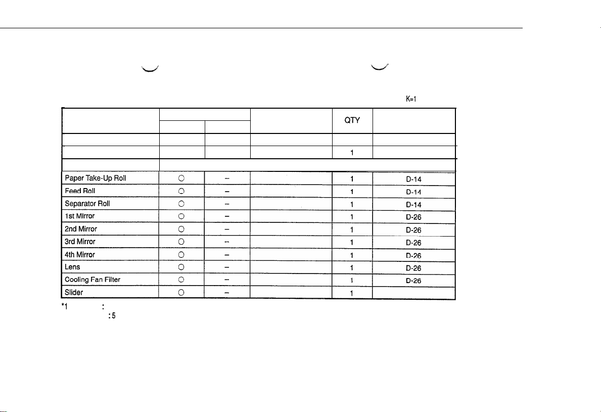
PAPER TAKE-UP SECTION
. OPTICAL SECTION
PM Parts
Paper Take-Up Roll
Synchronizing Roll
Multi Bypass Table
*l Inch Area : 4
Metric Area
l
: 5
PM Parts List
Maintenance Cycle (60K)
Clean
0
0
Replace
Parts No.
CITY
81
1
K=l
,000
copies
Disassembly Page
D-11
Page 3

l
IMAGEING UNIT
Toner Scattering
Ds Positioning
Collar (Front)
Ds Positioning
Collar (Rear)
Paper Dust Remover
Toner Antispill Mylar
Upper Pre-Image
Transfer Guide Plate
Magnet Roller
Lower Filter
0
0
-
0
-
0
0
1
1
1
1
1
1
D-29
D-29
D-29
D-29
D-30
D-30
Page 4

l
DRUM CHARGE/IMAGtiANSFER CORONAS
PM Parts
PC Drum Charge
Corona Housing
PC Drum Charge
Corona Grid Mesh
PC Drum Charge
Corona Comb Electrode
Image Transfer/Paper
Separator Corona Wires
Image Transfer/Paper
Separator Corona Housings
Lower Pre-Image
Transfer Guide Plate
Suction Belt
Ozone Filter
Parts No.
0
-
0
0
0
-
120
1139-4055-01 2
0
0
-
0
120
1139-4509-01
1 QTy /
Disassembly Page
1
1
1
1
1
4
1
D-33
D-33
D-34
D-34
D-34
D-35
D-l 2
D-35
Page 5

. FUSING UNIT
PM Parts
Pre-Fusing Guide Plate
Fusing Thermistor
Upper Fusing Roller
Lower Fusing Roller
Upper Separator Fingers
Lower Separator Fingers
Oil Roller
Cleanina Roller
Maintenance Cycle (60K)
Clean
0
0
0
0
0
0
0
0
Replace
-
Parts No.
QTY
1
1
1
1
4
5
1
1
Disassembly Page
D-36
D-38
D-38
D-39
D-38
D-39
D-40
Page 6

MINOLTA
Copyright
1996 MINOLTA CO., LTD
Printed in Japan
Use of this manual should
be strictly supervised to
avoid disclosure of
confidential information.
MINOLTA CO,, LTD
1158-7993-l 1 96113400
Printed In Japan
 Loading...