

Page 1
I
1159SBTOOOAA
EPlO3O/EP1030F
EP1031/EP1031F
'w
~ TROUBLESHOOTING
MINOllLA
Page 2
1159SBTOOOBA
CONTENTS
1
1 1 INTRODUCTION
l-1.
General Precautions
I-2.HowtoUseThisBook
1-3. Reading the Text
1
2 1 PAPER TRANSPORT FAILURE
1
........................................
......................................T- 1
...........................................
T-
1
T-
1
1
2-l. Misfeed Detection Types and Detection Timings
2-2. Misfeed Clearing Procedures
1) Copier Paper Take-Up Misfeed
2) TransportMisfeed
-
3) Multi Bypass Misfeed
4)
Exit Misfeed
5) SDH Misfeed
1
3 1 MALFUNCTIONS
3-l. Detection Timings Classified by Malfunction Codes
3-2. Troubleshooting Procedures
1) COO: Main Drive Motors Failure to Turn
2) C04: Ozone Fan Motors Failure to Turn
3)
C40:
Exposure Lamp Malfunction
4)
C50:
Warming-up Failure
051: Abnormally Low Fusing Temperature
C52: Abnormally High Fusing Temperature
5)
C60:
Scanner Drive Malfunction
C61:
Lens Drive Malfunction (EPI
6)
CFI:
AE Sensor Malfunction
7) CF3: ATDC Sensor Malfunction
8)
EO: EEPROM Malfunction
9)
El: IU Toner Detection Failure
E2: Blown IU Fuse Detection Failure
3-3. Power Malfunctions
........................................
.............................................
(EP1031/EP1031
1
.........................................
................................
.............................
(EP1031/EP1031
F)
F)
..........................
.................................
..........................
..................................
............................
031/EP1031
...............................
............................
.................................
.............................
........................
................
...................
.............
..............
.....................
...................
..................
.............
F)
.-c
....
T- 2
T- 4
T- 4
T- 6
T-
8
T-10
T-12
T-14
T-l 6
T-l 6
T-17
T-18
T-19
T-20
T-20
T-21
T-22
T-23
T-24
T-25
T-26
T-26
T-27
Page 3

~
5 IMAGE FAILURE
5-I. Image Failure Troubleshooting
5-2. Initial Checks
5-3. Troubleshooting Procedures Classified by Image Failure
..............................................
...............................
.........
T-28
T-28
T-29
Page 4
1139SSTOlOOA
INTRODUCTION
1159SBTOlOlA
l-l. General Precautions
1,
When servicing the copier with its covers removed, use utmost care to prevent your hands, clothing, and
tools from being caught in revolving parts including the chains and gears.
2. Before attempting to replace parts and unplug connectors, make sure that the power cord of the copier
has been unplugged from the wall outlet.
3. Never create a closed circuit across connector pins except those specified in the text and on the printed
circuit.
4. When creating a closed circuit and measuring a voltage across connector pins specified in the text, be
sure to use the green wire (GND).
5. When the user is using a word processor or personal computer from a wall outlet of the same line, take
necessary steps to prevent the circuit breaker from opening due to overloads.
6. Keep all disassembled parts in good order and keep tools under control so that none will be lost or damaged.
7. Adjust, choice, count, and other types of data are stored in TC3 (EEPROM) on Master Board PWB-A.
Keep this in mind and take necessary precautions when replacing PWB-A.
1139SBT0102A
I-2.
How to Use This Book
1,
If a component on a PWB or any
you to replace the whole
within the defective unit.
2. All troubleshooting procedures contained herein assume that there are no breaks in the harnesses and
cords and all connectors are plugged into the right positions.
3. For the removal procedures of covers and parts, see
4. The troubleshooting procedures are given in the order of greater frequency of trouble or order of operation
5. The procedures preclude possible malfunctions due to noise and other external causes.
1139SBT0103A
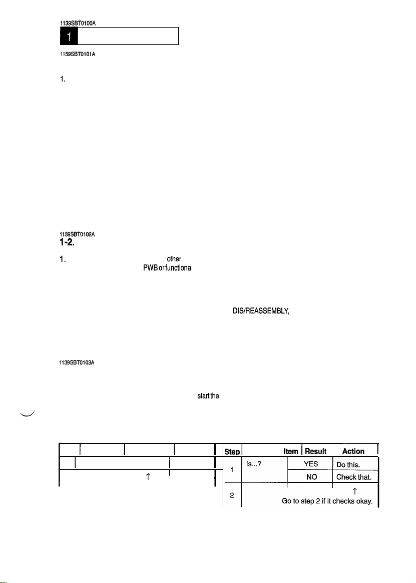
1-3. Reading the Text
1.
The paper transport failure troubleshooting procedures are given according to the symptom. First identify
the location where the paper is present and
troubleshooting, start with step 1 and onward.
2. Make checks in numerical order of steps and, if an item is checked okay, go to the next step.
other
PWBorfunctional
functional unit including a motor is defective, the text only instructs
unit and does not give troubleshooting procedures applicable
DIS/REASSEMBLY,
startthe
procedure for that particular location. For malfunction
ADJUSTMENT.
Pattern 1
Step 1 Check ItemIResult 1 Action
1 I Is...?
2
Go
to step 2 if you answered NO.
YES IDo this.
I
I
1 I
1
I
I
T-l
Pattern 2
Step1
Check
Item
I
Result
I
Aa
Page 5
1159SST0200A
PAPER TRANSPORT FAILURE
1159SBT0201A
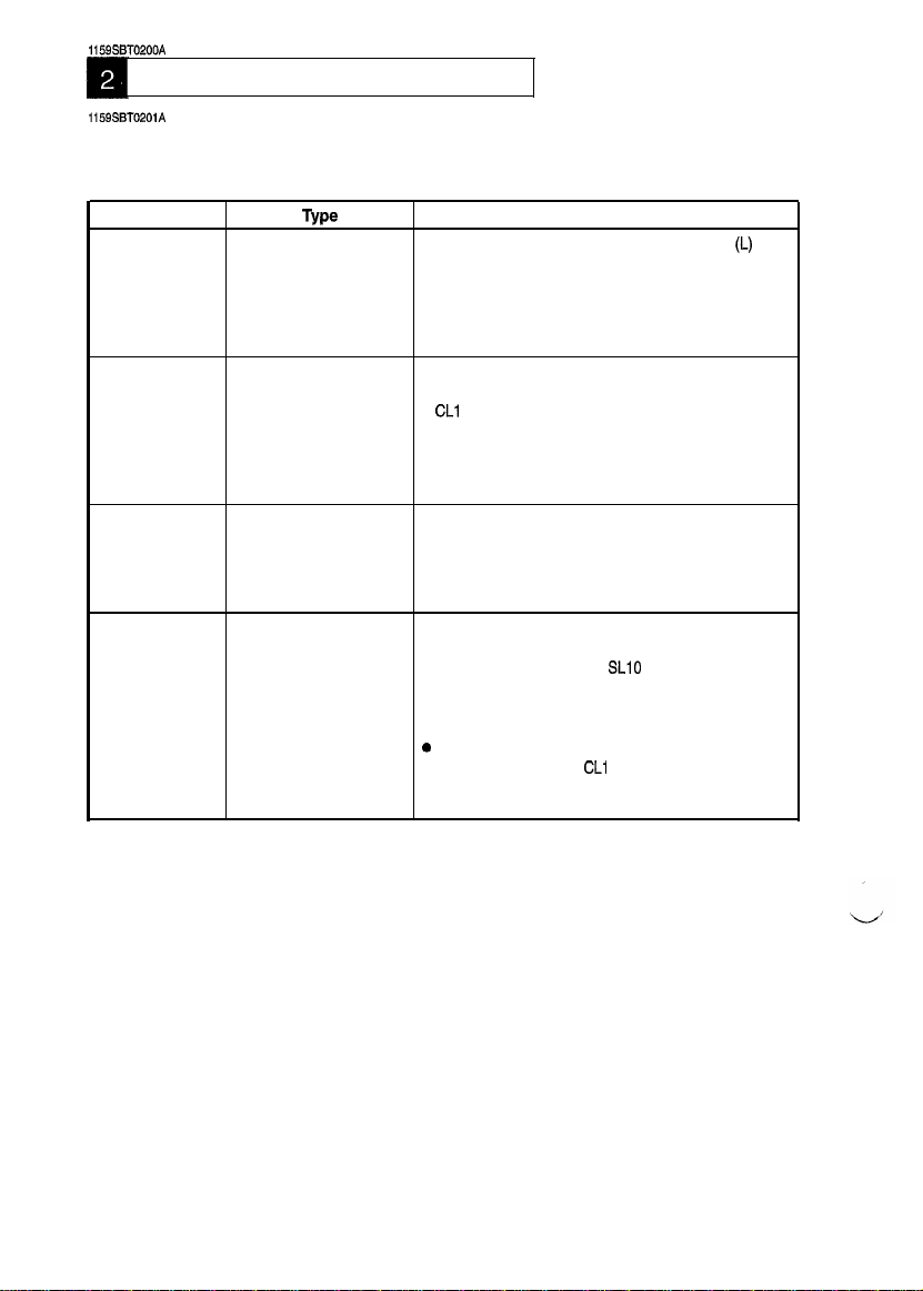
2-1. Misfeed Detection Types and Detection Timings
When a misfeed occurs, the corresponding misfeed code (the appropriate one of those shown below)
starts blinking to let the user know where the misfeed has occurred.
Misfeed Code
PC
J2
J3
J8
Type
Paper take-up misfeedl Paper Transport Sensor PC2 is not blocked
or Paper empty after the lapse of approx. 3.3 sec. after Paper
Take-Up Solenoid SL2 has been energized.
l
Paper Transport Sensor PC2 is not blocked (L) even
after the lapse of approx. 1.6 sec. after Multi Bypass
Paper Take-Up Solenoid SL3 has been energized.
Transport misfeed
l
Paper Exit Sensor PC3 is not blocked (L) even after
the lapse of approx. 2 sec. after Registration Clutch
CL1
has been energized.
l
PC2 is not unblocked (H) even after the lapse of
approx. 2.9 sec. (Cassette) or 3.2 sec. (Manual bypass) after Registration Clutch CL1 has been energized.
Exit misfeed
l
Paper does not move past Paper Exit Sensor PC3
even after the lapse of approx. 3 sec. after PC2 has
been unblocked (H).
l
PC3 remains blocked for approx. 2 sec. after CL1 has
been energized.
SDH misfeed
l
SDH Paper Transport Sensor PC23 is not blocked (L)
even after the lapse of approx. 2.3 sec. after SDH
Paper Take-Up Solenoid
l
SDH Original Exit Sensor PC24 is not blocked (L)
even after the lapse of approx. 1.3 sec. after SDH
Registration Clutch CL10 has been energized.
e
PC23 is not unblocked (H) even after the lapse of
approx. 4.4 sec. after
l
PC24 is not unblocked (H) even after the lapse of
approx. 1.7 sec. after PC23 has been unblocked (H).
Detection Timing
SLlO
has been energized.
CL1
0 has been energized.
(I_)
even
T-2
Page 6
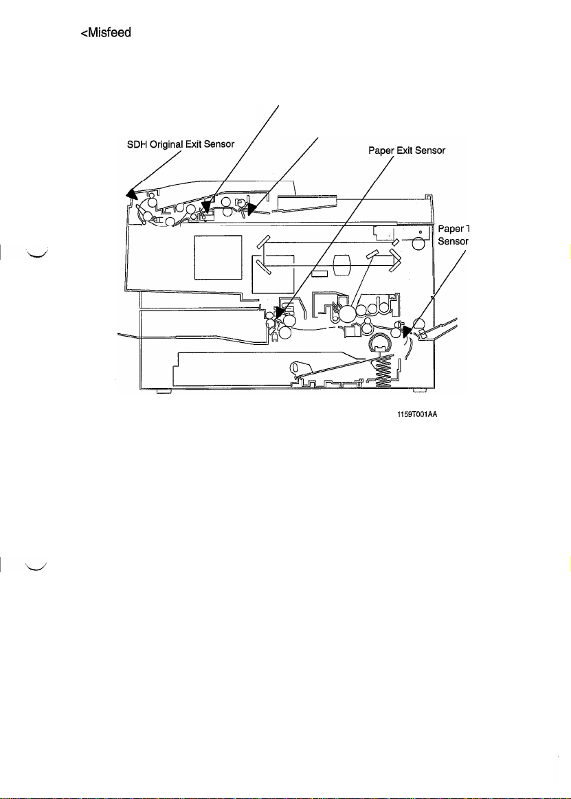
CMisfeed
Detecting Sensor Layout>
SDH Paper Transport Sensor
/
SDH Original Set Sensor
ransport
1159TOOlAA
T-3
Page 7
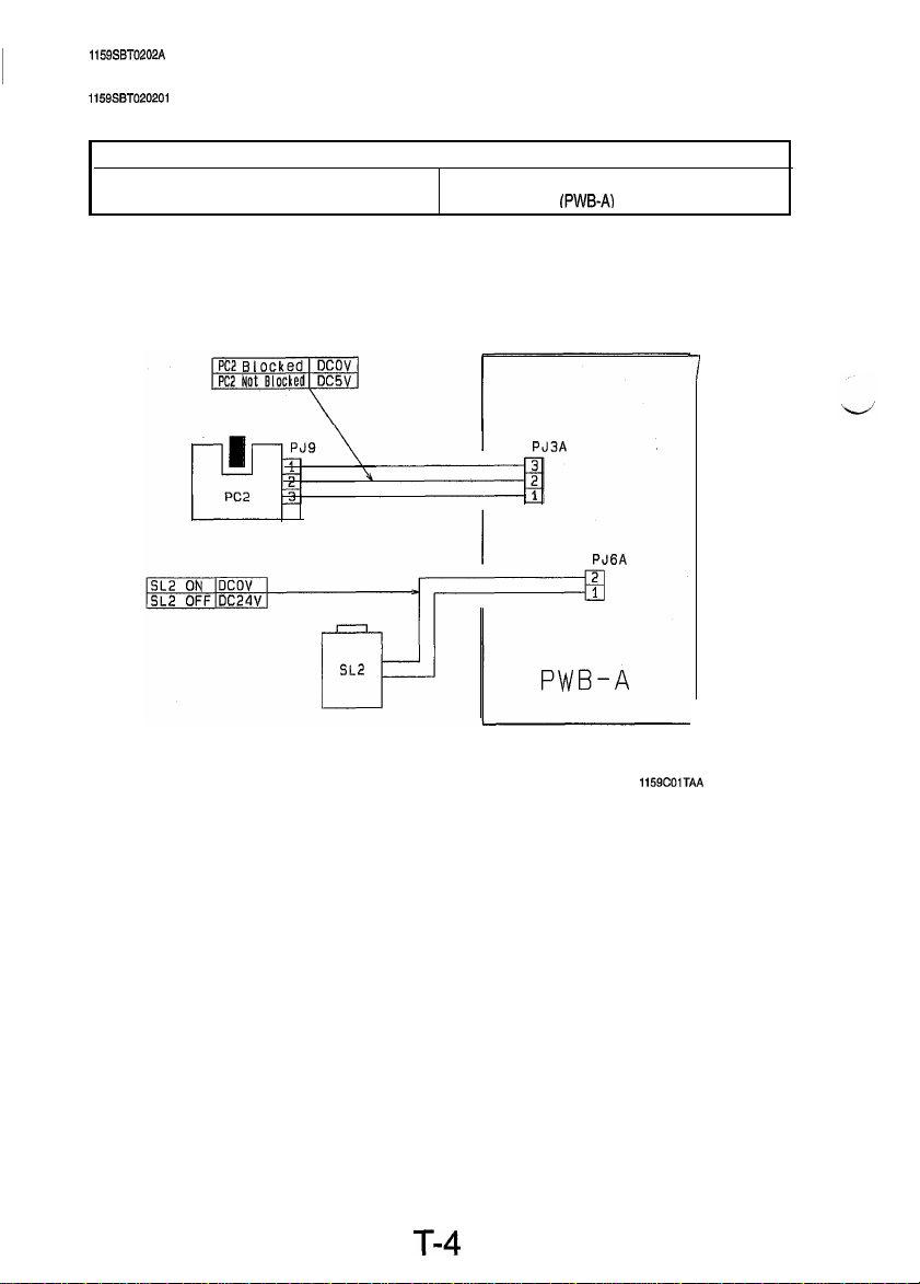
1159SBT0202A
2-2. Misfeed Clearing Procedures
1159SBTO20201
A
1) Copier Paper Take-Up Misfeed
Relevant Electrical Parts
l
Paper Transport Sensor (PC2)
l
Paper Take-Up Solenoid (SL2)
l
Master Board
(PWB-A)
7
T-4
1159COiTAA
Page 8
I
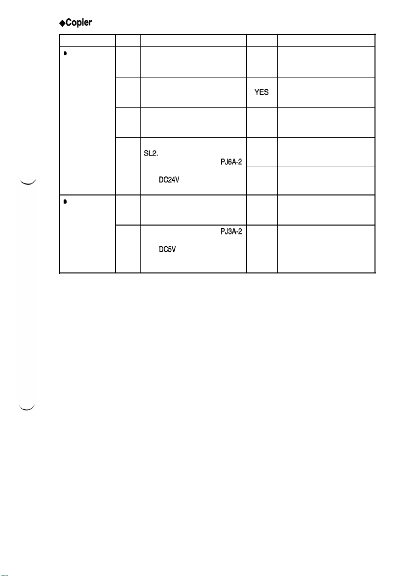
+Copier
Paper Take-Up Misfeed Clearing Procedure
Symptom
b
Paper is not
taken up at all.
s
Paper is
stationary at 1
the Transport
Rollers.
Step
Does the paper being used
meet product specifications?
1
Is the paper curled, waved, or Change the paper. Instruct
2
damp?
Is the Paper Take-Up Roll
deformed, worn, or dirty with
3
paper dust?
Check Paper Take-Up Solenoid
SL2.
Does the voltage across
4
on PWB-A and GND change
from
Start key is pressed?
Are the Transport Rollers
deformed, worn, or ditty with YES
paper dust?
Does the voltage across
on PWB-A and GND change operation and, if it checks
from
2
Paper Transport Sensor PC2 is
blocked?
Check item
DC24V
to DCOV when the
DC5V
to DCOV when
PJ6A-2
PJ3A-2
Result
instruct the user to use the
NO
paper that meets product
specifications.
the user in how to store the
YES
paper.
Clean or change the Paper
YES
Take-Up Roll.
Change SL2.
YES
Change PWB-A.
NO
Clean or change the Paper
Take-Up Roll.
Check the PC2 actuator for
okay, change PC2.
NO
Action
T-5
Page 9
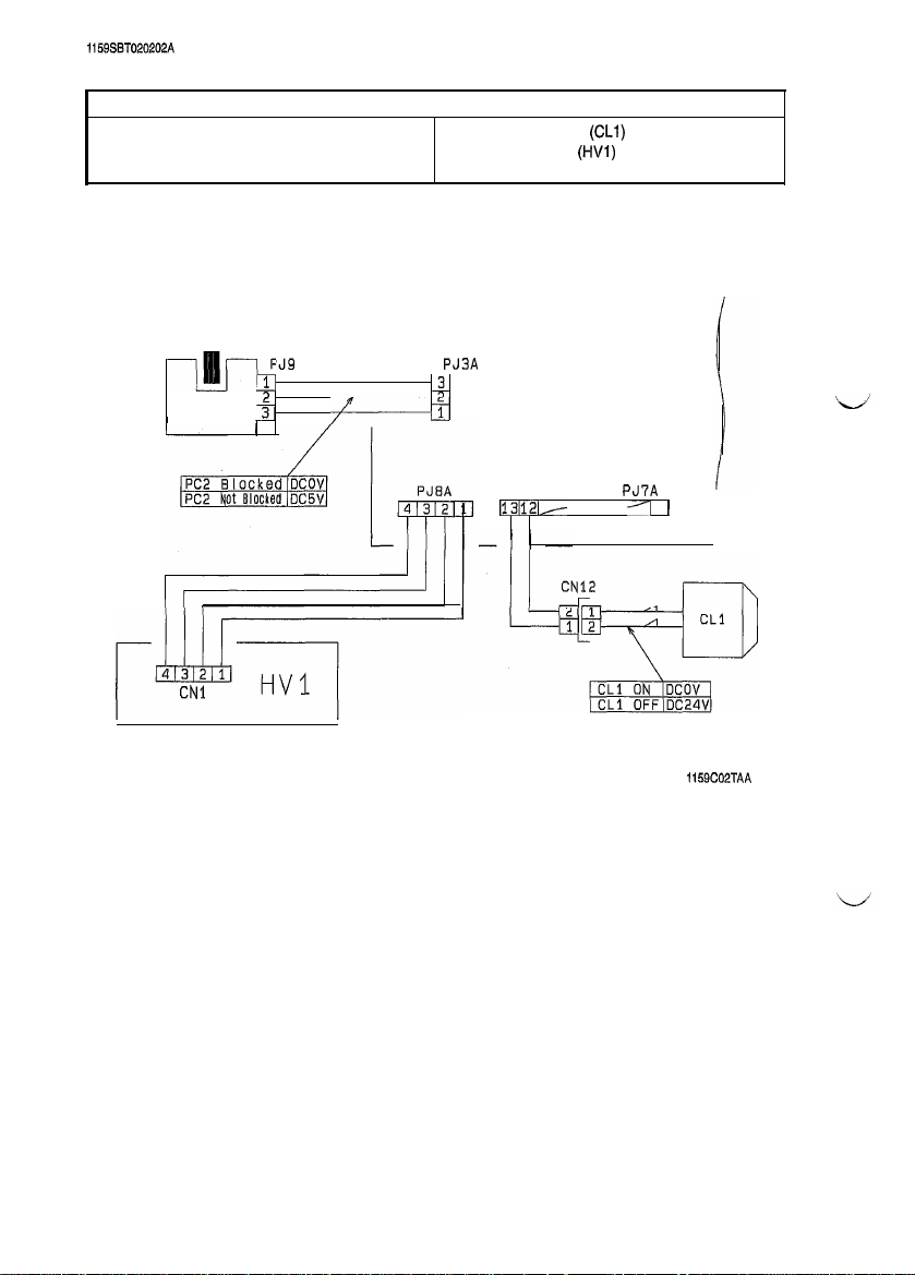
1159SST020202A
2) Transport Misfeed
l
Paper Transport Sensor (PC2)
Relevant Electrical Parts
l
Registration Clutch
l
High Voltage Unit
l
Master Board (PWB-A)
(CLI)
(HVl)
-p!lJ--
PC2
p&q----
CNl
PJ9
1 3
j&
3
I
I------l
PJ3A
1
Il3112b-
PWB-A
PJ7A
/I
1
I
1159C02TAA
T-6
Page 10
I
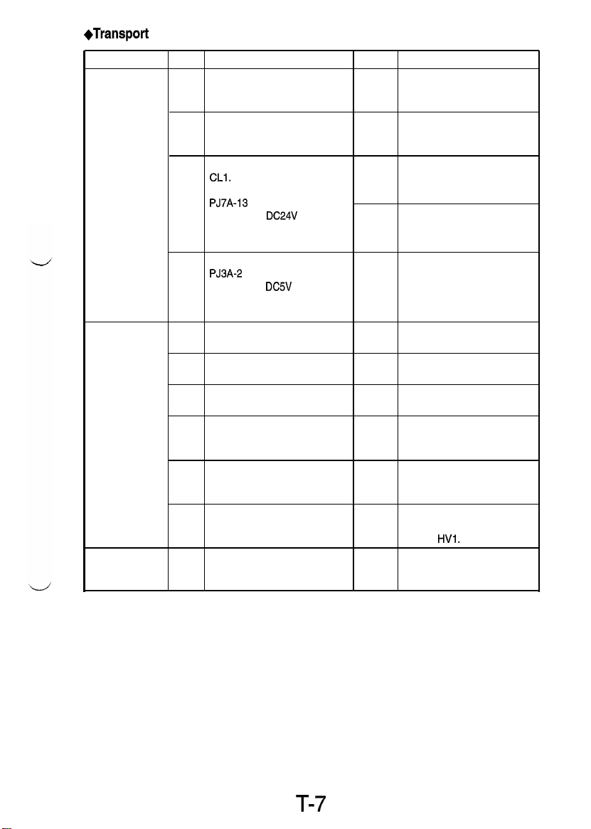
*Transport
Symptom
Paper is Is the paper curled, waved, or
stationary at the
Synchronizing paper.
Roller.
Paper is
stationary near
the PC Drum.
Paper is
stationary before 1
the Fusing Unit.
Misfeed Clearing Procedure
Step
1
2
3
4
1
2
3
4
5
6
Check Item
damp?
Does the paper being used Instruct the user to use the
meet product specifications? NO paper that meets product
Check Registration Clutch
CLl.
Does the voltage across
PJ7A-13 on PWB-A and GND
change from DC24V to DCOV
after the Start key has been
pressed?
Does the voltage across Check the PC2 actuator for
PJ3A-2 on PWB-A and GND
change from DC5V to DCOV
when Paper Transport Sensor
PC2 is blocked?
Is the Pre-Image Transfer
Guide Plate deformed or dirty?
Is the Image Transfer Corona
wire deteriorated or dirty?
Is the Comb Electrode
deteriorated or dirty? Electrode.
Is the paper guide at the Paper
Separator Corona deformed or
dirty?
Are the Synchronizing Rollers
deformed, worn, or dirty with
paper dust?
Is paper wound around the PC
Drum?
Do the Fusing Rollers turn
when the Main Drive Motor is
energized?
Result Action
Change the paper. Instruct
YES the user in how to store the
specifications.
Change CL2.
YES
Change PWB-A.
NO
operation and, if it checks
NO
okay, change PC2.
Clean or change the guide
YES
plate
Clean or change the wire.
YES
Clean or change the Comb
YES
Clean or change the paper
YES
guide.
Clean or change the
YES Synchronizing Rollers,
Change the Image Transfer/
YES
Paper Separator Coronas
Assy or
HVl.
Check the drive transmission
NO
path.
T-7
Page 11
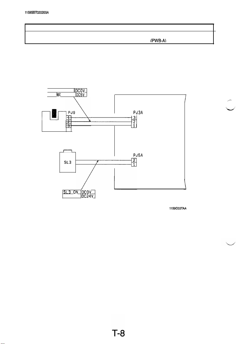
1159SBT020203A
3) Multi Bypass Misfeed
l
Paper Take-Up Sensor (PC2)
Relevant Electrical Parts
l
Multi Bypass Paper Take-Up Solenoid (SL3)
l
Master Board fPWB-AI
PC2 Blocked 1
PC2
-lllJ-
PC2
t@t
Blocked I
r-l
SL3
SL3 olu lDCOV
SL3 OFF
DCOV
DCSV
IDC24V
I
PJ3A
-+
1
PWB-A
PJ5A
1159C03TAA
Page 12
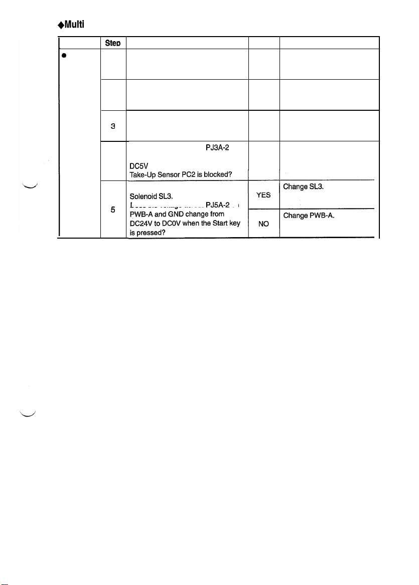
+Multi
I
Bypass Misfeed Clearing Procedure
Symptom
0
Paper is
not taken
up at all.
Stecb
Does the paper being used meet
product specifications?
Is the paper curled, waved, or
damp?
2
Is the Multi Bypass Paper Take-Up
Roll deformed, worn, or dirty with
3
paper dust?
Does the voltage across PJ3A-2 on
PWB-A and GND change from
4
DC5V to DCOV when Paper
Check Multi Bypass Paper Take-Up
Does the voltage across PJ5A-2 on
5
Check Item
Result
Instruct the user to use the
NO paper that meets product
specifications.
Change the paper. Instruct
the user in how to store the
YES
paper.
Clean or change the Multi
Bypass Paper Take-Up Roll.
YES
Check the PC2 actuator for
operation and, if it checks
NO
okay, change PC2.
Action
T-9
Page 13

1159SST020204A
4) Exit Misfeed
l
Paper Exit Sensor (PC3)
Relevant Electrical Parts
l
Master Board (PWB-A)
PJ'IA
PWB-A
1159C04TAA
T-10
Page 14

+Exit
Misfeed Clearing Procedure
Are the
Separator Fingers deformed,
Fusing Roller Paper
defective paper separator
T-11
Page 15

1159SBT020205B
5) SDH Misfeed
l
SDH Paper Transport Sensor (PC23)
l
SDH Original Set Sensor (PC22)
l
SDH Original Exit Sensor (PC24)
(EP1030F/EP1031
F)
Relevant Electrical Parts
l
SDH Paper Take-Up Solenoid
l
SDH Drive Motor
l
SDH Registration Clutch
. SDH PWB (PWB-C)
l
Master Board
(MlO)
(PWB-AI
(CLlO)
(SLl
0)
T-12
1159CO5TAB
Page 16

+SDH
I
Misfeed Clearing Procedure
Symptom
Iocument
lot
taken up at ,
FlII.
Document is
stationary at
the Registration paper dust?
Roller.
Document is
stationary at
the Exit Roller.
Step
is
Does the document being used
meet specifications for reliable
feeding?
Do the documents loaded
2
teed the capacity of the SDH?
Are the Document Take-Up and Clean or change the
Separator Rolls deformed, YES
3
worn, or dirty with paper dust?
Does the voltage across
on PWB-C and GND change
from
4
Original Set Sensor PC22 is
blocked?
Check SDH Drive Motor Ml 0.
Is the voltage across
5
PWB-A and GND
the Start key is pressed?
Check SDH Paper Take-Up
Solenoid
Does the voltage across
6
on PWB-A and GND change
from
Start key is pressed?
Is the Registration Roller
deformed, worn, or dirty with YES
1
Does the voltage across
on PWB-C and GND change
2
from
Paper Transport Sensor PC23
is blocked?
Check SDH Registration Clutch
CL1 0.
Does the voltage across
3
on PWB-A and GND change
from
Start key has been pressed?
Is the Exit Roller deformed,
1
worn, or dirty with paper dust?
Does the voltage across
on PWB-C and GND change
from
2
Original Exit Sensor PC24 is
blocked?
Check Item
DC5V
to DCOV when SDH
SLlO.
DC24V
DC5V
DC24V
DCZV
to DCOV when SDH
ex-
PJ4C-2
PJl A-8
on
DC24V
when
PJl
A-6
to DCOV when the
PJ4C-5
to
DCOV when SDH
PJl
A-7
to DCOV after the
PJ4C-9
Result Action
Instruct the user to use a
document that meets
NO
specifications for reliable
feeding.
Ask the user to keep within
YES
the SDH document capacity.
Document Take-Up and
Separator Rolls.
Check the PC22 actuator for
operation and, if it checks
okay, change PC22.
NO
Change PWB-A or PWB-C.
NO
Change Ml 0.
YES
Change
SLl
YES
Change PWB-A or PWB-C.
NC
Clean or change the
Registration Roller.
Check the PC23 actuator for
operation and, if it checks
okay, change PC23,
NO
Change CL1 0.
YES
Change PWB-A or PWB-C.
N
O
Clean or change the Exit
YES
Roller.
Check the PC24 actuator for
operation and, if it checks
NO
okay, change PC24.
YES
Change PWB-C.
0.
T-13
Page 17

1159SBT0300A
MALFUNCTIONS
1159SBT0301A
3-1,
Detection Timings Classified by Malfunction Codes
Code
Description
Detection Timing
Main Drive Motor Mlsl The lock signal remains HIGH for a continuous I-sec. or
coo
failure to turn
period while Ml remains energized,
l
The lock signal remains LOW for a continuous 1 -sec. or more
period while Ml remains deenergized.
Ozone Fan Motor
co4
failure to turn
Exposure Lamp LA1
malfunction
c40
The lock signal remains HIGH for a continuous 1 -sec. or more
M3s
period while M3 remains energized.
l
The AE Sensor output at 91 msec. after the start of a scan motion
with LA1 ON is lower than the AE Sensor output when LA1 is
OFF.
l
The AE Sensor output at any timing when the Scanner is at home
position with LA1 OFF is higher than the AE Sensor output when
LA1 is ON.
Warming-up failure
The surface temperature of the Upper Fusing Roller does not
reach a given level after a given period of time during
warming-up as detailed below:
l
c50
Abnormally low fusing The surface temperature of the Upper Fusing Roller is below
c51
temperature
Abnormally high fusing
C52
temperature
Scanner drive
malfunc-
tion
From room temperature to
l
From 45 to
l
From 80 to 115C: 10 sec.
l
From 115 to 145C: 15 sec.
l
From 145 to
150C
after the copier has completed warming up.
80C:
160C:
10 sec.
The surface temperature of the Upper Fusing Roller is
higher after the copier has completed warming up.
<When the Power Switch is turned ON>
l
When the Scanner is at the home position, Scanner Home
Position Sensor
PC1
1
45C: 10
sec.
15 sec.
does not go from LOW to HIGH even after
the lapse of 1 sec. after the Scanner has started a scan motion.
l
When the Scanner is at a position other than home,
C60
not go from HIGH to LOW even after the lapse of 8.4 sec.
the Scanner has started a scan motion.
<When
the Start key is pressed>
l
PC11 does not go from LOW to HIGH even after the lapse of
1 sec. after the Scanner has started a scan motion.
l
PC11 does not go from HIGH to LOW even after the lapse of
8.4 sec. after the Scanner has started a return motion.
230C
PC11
more
or
does
after
T-14
Page 18

Code
1
Description
l
Lens drive malfunction
C61
AE Sensor malfunction
CFl
ATDC Sensor malfunction The output from ATDC Sensor UN3 is
CF3
EEPROM malfunction Data which must be retained even when power is turned OFF
EO
IU toner detection failure
Blown IU fuse detection
E2
failure
Lens Home Position Sensor PC12 does not go from LOW to
HIGH even when Lens Drive Motor M5 is energized for 750
pulses for the lens movement in the reduction direction.
l
PC12 does not go from HIGH to LOW even when M5 is
energized for 1400 pulses for the lens movement in the
enlargement direction.
The output from AE Sensor Board PWB-E is
less than
at home position.
than
cannot be written to, and read from, the EEPROM.
The output from ATDC Sensor UN3 remains less than 1 .OV
during an F8 operation.
The IU fuse is not blown during an F8 operation.
0.4V
0.4V.
Detection Timing
4.8V
when the Exposure Lamp is OFF and Scanner
4.8V
or more, or
or more, or less
T-15
Page 19

1159SBT0302A
3-2. Troubleshooting Procedures
1159SBTO30201
A
1) COO: Main Drive Motors Failure to Turn
Relevant Electrical Parts
l
Main Drive Motor (Ml)
l
Power Supply Unit
l
Master Board (PWB-A)
(PUl)
Step Check Item
Does the voltage across
1
from
DC5V
to DCOV when the Start key is pressed?
Is the voltage across
2
Power Switch Sl is turned ON?
Is the voltage across
3
is turned ON?
PJ4A-4
on PWB-A and GND change
PJ4A-3
on PWB-A and GND DCOV when
PJ4-1
on
PUl
and GND
DC24V
T-16
when
1159CWTAA
Result
NO
YES
Sl
NO
Action
Change PWB-A.
Change Ml.
Change
PUl.
Page 20

2) C04:
Ozone Fan Motors Failure to Turn
I
Relevant Electrical Parts
l
Master Board (PWB-A)
1159C07TAA
Check
step
Does the voltage across
1
from DC1 2V to DC24V when the Stat-t kev is Dressed?
Is the voltage across
2
when Sl is turned ON?
PJ13A-3
Item
PJ13A-1
on PWB-A and GND change
on PWB-A and GND
DC5V
Result
NO
I
YES
Actim
Change PWB-A.
I
Change M3.
I
Page 21

Ii 59SBT030203A
3)
C40:
Exposure Lamp Malfunction
I
Relevant Electrical Parts
PJlF
l-2.l
I
PWB-F
1159COBTAA
SteteD
I
Is the source voltage being supplied across
1
and -BR on PWB-F?
Is the circuit across PJGF-1 and -2 on the LA1 side
2
conducting when
Check Item
PJGF
is removed from PWB-F?
CNl
T-18
F-GY
I
Result
NO
I
I
Action
Check the power line.
I
I
I
Page 22

1159SBT030204A
4)
C50:
Warming-up Failure
C51:
Abnormally Low Fusing Temperature
C52: Abnormally High Fusing Temperature
Relevant Electrical Parts
l
Fusing Thermistor
l
Fusing Thermoswitch
(THl)
(TSI)
TSI
. AVR (PWB-F)
l
Master Board (PWB-A)
y
Fusing Rol
ler
1
PJ5F
1159C09TAA
T-19
Page 23

e
continuity
across
PJ4F
and
PJ5F
on
PWB-F
Change the
Fusing Unit.
Measure the
+C52
I
SteD
I
1
Is
THl
installed properly, or dirty? YES Reinstall or clean
Measure the resistance of
2
O?
resistance of THI.Isit
Check Item
THl
.
Is
infinite?
it 00 or close to
1
Result
I
YES Change
NO
Channe
Action
THl
.
THl
.
PWB-F or PWB-A.
1
T-20
Page 24

1159SBT030205A
5)
C60:
Scanner Drive Malfunction
C61: Lens Drive Malfunction
(EP1031/EP1031
F)
I
l
Scanner Home Position Sensor
l
Lens Home Position Sensor (PC12)
I
Relevant Electrical Parts
(PCll)
l
Scanner Drive Motor (M4)
l
Lens Drive Motor (M5)
l
Master Board
fPWB-A\
I
I
T-21
1159CiOTAA
Page 25

+C60
Step
I
Does the voltage across PJ
1
change from
Position Sensor
Is
PJll
A
2
on PWB-A connected properly?
+C61
Step
I
Does the voltage across PJ
1
change from
Sensor PC12 is blocked?
Is
PJ12A
2
on PWB-A connected properly? YES
Check Item
16A-5
DCXV
to DCOV when Scanner Home
PC1
1 is blocked?
Check Item
DCXV
to DCOV when Lens Home Position
on PWB-A and GND
17A-2
on PWB-A and GND
1
Result
YES
NO
I
Result
NO
1
Action
Change PWB-A or M4.
Connect it
I
Change PWB-A or M5.
Connect It properly.
orooerlv.
Action
I
T-22
Page 26

1159SBT030206A
6)
CFI:
AE Sensor Malfunction
l
AE Sensor Board (PWB-E)
Relevant Electrical Parts
l
Master Board (PWB-A)
PJlE '
-
PWB-E
Check
!N?p
Is
the voltage across
1
DC4.8V
or more, or
Lamp is OFF and Scanner at home position
0.4V
item
PJ18A-2
on PWB-A and GND
or less when the Exposure
PJ16A
:
3
4
6
6
PWB-A
1159CllTAA
R@sult
YES
NO
I
Action
Change PWB-E.
Change PWB-A.
T-23
Page 27

1159SST030207A
7) CF3: ATDC Sensor Malfunction
Relevant Electrical Parts
l
ATDC
Sensor
(UN3)
PWB-A
PJIOA
l
Master Board (PWB-A)
Is the voltage across
1
DC4.8V
or more, or
PJlOA-1
on PWB-A and GND
0.4V
or less?
T-24
1159C12TAA
I Result I
YES Change UN3.
f’.hanne
Action
PWR-A
Page 28

115993T030203A
8) EO: EEPROM Malfunction
i
I
l
Master Board (PWB-A)
Step
Does
EO
1
2
3
appear again after the malfunction has been
reset?
Does EO appear during a copy cycle? YES Change EEPROM.
Does
EO
appear when the Power Switch is turned ON? YES Change PWB-A.
Relevant Electrical Parts
Check Item Result Action
YES
I
I
Change EEPROM.
T-25
Page 29

1l59SET030209A
9) El: IU Toner Detection Failure
E2: Blown IU Fuse Detection Failure
Relevant Electrical Parts
l
ATDC Sensor
(UN3)
El
0
Imaging Unit (IU)
l
Master Board
(PWB-A)
Step Check Item
1
Did you peel off the seal from the Toner Cartridge?NOPeel off the seal.
Has the starter been loaded?
2
Result Action
YES
E2
Step
1
Check Item
Is the fuse blown?
Result
YES
Change
UN3 or PWB-A.
Action
Chanae the fuse or
-.
LA
PWB-A.
T-26
Page 30

I
1159SST0303A
3-3. Power Malfunctions
Power is not Turned ON (Control Panel Shows Nothing)
I
l
Power Switch
l
Noise Filter Board (PWB-D)
(Sl)
Relevant Electrical Parts
. AVR (PWB-F)
0
Power Supply Unit
l
MSC Board (PWB-B)
l
Master Board (PWB-A)
I
(PUI)
Step
1 Is the source voltage applied across 1 and 3 of
Is the source voltage being applied across 2 and 4 of
when it is turned ON?
Is the source voltage being applied across 1 and 2 of
PJ3 on PUl when Sl is turned ON?
Is the voltage across
DC24V
when Sl is turned ON?
Is the voltage across
GND
DC24V
Are PJ20A on PWB-A and
properly?
6
Check Item
PJSA-1
to -3 on PWB-A and GND
PJSA-1,
when Sl is turned ON?
-2, and -5 on PWB-A and
PJl
B on PWB-B installed
T-27
Sl?
1159C13TAA
Result
I
Action
Sl
Change PWB-F.
NO
Change PUl,
NO
Check the wiring
tween PUl and
NO
PWB-A and, if it is in-
tact, change
Change PWB-A,
PWB-B, and the
YES
harness, in that order.
NO
)
Install them properly.
be-
PUl.
Page 31

1149SAT0600A
IMAGE FAILURE
1159SBT0501A
5-1. Image Failure Troubleshooting
Image failures have many possible causes. For troubleshooting, it
is necessary to determine whether
ure is attributable to a basic cause or any other cause.
In this chapter, troubleshooting is divided into initial checks and troubleshooting procedures classified by
image failure. If an image failure has occurred, first make the initial checks, then proceed to the corresponding image failure troubleshooting procedure.
1159SBT0502A
5-2, Initial Checks
1)
Place of installation
l
Is the source voltage normal? Does the voltage vary greatly?
l
Is the copier installed in a hot, humid place or in a place where temperatures vary sharply?
l
Is the copier installed in a dusty place?
l
Is the copier subjected to direct sunlight?
l
Is the copier level?
2)
COPY
paper
l
Is the recommended paper used?
*Load
recommended paper and make copies to see if the problem persists.
l
Is the paper damp?
*Load
new paper and make copies to see if the problem persists.
3)
Original
l
Does the original used have a reddish background or is it written in light pencil?
*Use
the Test Chart to check the image.
l
Is the original transparent or are transparencies being used?
&over
with white paper and make a copy.
l
Are the Original Glass and ADF Transport Belt dirty or scratched?
*If
dirty, clean with alcohol. If scratched, replace.
a
fail-
5) Adjustment items (registration, focus, AE level, etc.)
l
Among the adjustment items given in
DIS/REASSEMBLY,
ADJUSTMENT, is there any adjustment that
may remedy the image failure?
T-28
Page 32

1149SST0503A
5-3. Troubleshooting Procedures Classified by Image Failure
<Image
Failure Samples>
1) Blank copy
4) Foggy background
7) Blank streaks or bands
5) Black streaks or bands
8) Void areas
3) Low image density
6) Black spots
9) Smear on back
-b
3C:DE
P 3C:DEI
1E 3C:DEI
I! 3C:DEE
P 3C:DEI
4’~CDE
9BCDI
ABWE
ABLOE
A3CDE
T-29
1
ABCDE
1149T012AA
1
Page 33

1159SBT050301A
1) Blank Copy
Exposure Lamps
failure to turn ON
Voltage Unit
PC Drum
Voltage Unit HVl
Is the PC Drum properly
grounded?
Is the developing bias contact normal?
Has condensation formed
on the mirrors, lens, or PC
Drum?
Are the mirrors installed
4
properly?
Does the Exposure Lamp
5
liaht uo?
HVI
Charge Corona
Check
Item
and the
and
ooro-
I
Result
NO
NO
YES
NO
NO
Action
Clean or change the PC
Drum.
Clean or replace the developing bias contact.
Clean the mirrors and lens,
and run the Drum Dehum.
operation.
Reinstall the mirrors.
Take the action for malfunction code
C40.
T-30
Page 34

I
1159SBT050303A
3) Low Image Density
rid mesh normal?
dirty or covered
with con-
T-31
Page 35

I
1159SST050304A
4) Foggy background
Cause
Cleaning failure
Optical failure
PC Drum failure
Developing failure
1159SRT050305A
I
Stet3
1
1
2
1
3
4
I-
5
6
c
Is the Cleaning Blade dirty
with foreign matter, paper
dust. etc. or is it scratched?
Are the mirrors and lens
dirty?
Is the PC Drum dirty with
foreign matter, etc.?
Is the PC Drum properly
grounded?
Is the Sleeve Roller abnormally dirty?
Is the developing bias contact normal?
5) Black Streaks or Bands
Are the Comb Electrode
and grid mesh dirty?
1
Cleaning failure
PC Drum failure
Optical failure
I
I
Is the Cleaning Blade dirty
with foreign matter, paper
2
dust, etc., or is it
scratched?
Is the PC Drum surface
dirty or scratched?
3
Is the Upper Fusing Roller
dirty or scratched?
Are the Upper Paper Sepa-
rator Fingers dirty or
formed?
Are the mirrors and lens
dirty with foreign matter?
Check Item
Check Item
de-
Resul;
YES
YES
YES
NO
YES
NO
I
Result
YES
YES
YES
YES
YES
YES
Action
Change the Cleaning
Blade.
Clean the mirrors and lens.
Clean or replace the PC
Drum. Change the Cleaning
Blade if necessary.
Clean or change the PC
Drum.
Clean the Sleeve Roller.
Check the Developer Scattering Prevention Seal to
see if it is deformed or dirty.
Clean or change the developing bias contact.
Action
Clean or replace the PC
Drum Charge Corona.
Check the toner suction
mechanism for operation.
Change the Cleaning
Blade.
Change the PC Drum. If
necessary, change the
Cleaning Blade.
Clean or replace the Upper
Fusing Roller.
Clean or replace the Upper
Paper Separator Fingers.
Clean the mirrors and lens.
T-32
Page 36

I
1159SBT050306A
6) Black Spots
Fusing failure
Developing failure
1159SBT050307A
r
2
3
4
5
7) Blank Streaks or Bands
Cause
Plugged Db
Drum charge failure
Image transfer
ure
Image Erase Lamp
lit at abnormal timing
fail-
I Step
1
2
3
4
Check Item
Is the PC Drum surface
scratched or dirty with
eign matter?
Is the Upper Fusing Roller
dirty or scratched? YES
Is the amount of toner on
the Sleeve Roller proper?
Is the toner-to-carrier ratio
relatively high?
Is the Developer Scattering
Prevention Seal deformed
or dirty?
Check Item
Is Db plugged with foreign
matter, caked toner, etc.? YES
Are the Comb Electrode
and grid mesh dirty?
Is the Image Transfer Corona wire dirty?
for-
I
Result
YES
YES
YES
YES
1
Result
YES
YES
Action
Clean or change the PC
Drum. Change the Cleaning
Blade if necessary.
Check the Fusing Thermistors. Clean or change the
Upper Fusing Roller.
Go to step 5.
Change the toner-to-carrier
ratio.
Clean or change the Developer Scattering Prevention
Seal.
Remove foreign matter. If
the problem persists,
change the developer.
Clean or change the PC
Drum Charge Corona.
Clean or change the Image
Transfer Corona.
Check the Image Erase
Lamp.
Fusing failure
5
6
Clean or change the Upper
Fusing Roller.
Clean
or change
Paper Separator
the Upper
Fingers.
T-33
Page 37

1159SBT050308A
8) Void Areas
Cause
Image transfer
ure
Damp copy paper
Small amount of toner supplied
Paper guide shorting
Fusing failure
1159SBT050309A
fail-
9) Smear on Back
Cause
Dirty Developing
Unit
Dirty Image Transfer
Corona
Dirty Fusing Unit
Step
1
2
5
6
Step
1
2
3
4
5
Check Item
Is the Image Transfer Coro-
na installed properly?
Is the Image Transfer
na wire dirty?
Is the paper guide shorted
to the frame?
Is the Lower Fusing Roller
scratched or deformed?
Check Item Result Action
Is the bottom part of the
Developing Unit dirty?
Is the Image Transfer
na dirty?
Is the Pre-Image Transfer
Guide Plate dirty?
Is the Fusing Unit Entrance
Guide Plate dirty?
Are the Upper and Lower
Fusing Rollers dirty?
Result Action
NC
Coro-
YES
NO
YES
YES
YES
Coro-
YES
YES
YES
YES
Reinstall.
Clean or change the Image
Transfer Corona wire.
Change the copy paper and
instruct the user in how to
store paper.
Check the Db value and
amount of developer, and
check the Bucket Roller for
operation.
Connect the paper guide
through the resistor to the
frame.
Replace the Lower Fusing
Roller.
Clean and check the
oper Scattering Prevention
Seal.
Clean the corona and
check the Developing Unit.
Clean the guide plate and
check the Developing Unit.
Clean the guide plate and
check the Developing Unit.
Clean or change the Upper
and Lower Fusing Rollers.
Devel-
T-34
Page 38

I
1159SBTOOOEA
MINOUA
Copyright
1997
MINOLTA
Printed in Japan
Use of this manual should
be strictly supervised to
avoid disclosure of
confidential information,
MINOLTA
Co., Ltd.
CO,, LTD,
I
1159-7998-l
1 97074370
Printed in Japan
 Loading...