

Page 1
I
1l$9SBSOOOAA
EP1030/EP103OF
~EPl031/EP1031F
~ SWITCHES ON
PWBs/
~ TECH, REP, SETTINGS
MINOLTA
Page 2
ll59SSSOOOSA
CONTENTS
1
PRECAUTIONS FOR HANDLING THE
l-1. Precautions for Transportation and Storage
1-2. Precautions for Replacement and Inspection
2
CONTROL PANEL KEYS AND INDICATORS
.
EP1031/EP1031
. EPI
030/EP103OF
F
. . . . . . . . . . . . . . . . . . . . . . . . . . . . . . . . . . . . . . . . .
. . . . . . . . . . . . . . . . . . . . . . . . . , . . . . . n . . . , , . . .
PWBs
. . . . . . . . . . . . . . . . . . .
. . . . . . . . . . . . . . . .
S-l
. . . . . . . . . . . . . . .
. . . . . . . . . . . . . . . . . . .
S-2
.
S-4
S-l
S-l
s-2
4 USER MODE
4-l. Functions Available from User Mode
4-2. User Mode Setting Procedure
4-3. User Mode Setting Details
5 SERVICE MODE
5-1.
Service Mode Function Tree
5-2.
Entering the Service Mode
Counter Display Procedure
5-3.
Setting in the Service Mode ..............................
5-4.
l.Display
2. Tech. Rep. Choice
3.Adjust ...............................................
4.Test .................................................
6
FUNCTION SETTING REQUIREMENTS AT REPLACEMENT OF PART
.................................
......................
............................
...............................
.............................................
..............................
...............................
...............................
..............................................
....................................
..i
............
. .
m
S-6
S-6
S-6
S-6
s-7
S-7
S-7
S-8
S-9
S-9
S-10
S-13
S-16
S-l 8
Page 3

1151SSSOlOOA
PRECAUTIONS FOR HANDLING THE
1151SBS0101A
PWBs
1-1. Precautions for Transportation and Storage
a) Before transporting or storing the
are not subjected to high temperature (and they are not exposed to direct sunlight).
b) Protect the
c) Once the PWB has been removed from its conductive case or bag, never place it directly on an object
that is easily charged with static electricity (such as a carpet or plastic bag).
d) Do not touch the parts and printed patterns on the
1151SSS0102A
PWBs
from any external force so that they are not bent or damaged.
PWBs,
put them in protective conductive cases or bags so that they
PWBs
with bare hands.
1-2. Precautions for Replacement and Inspection
a) Whenever replacing the PWB, make sure that the power cord of the copier has been unplugged.
b) When the power is on, the connectors should never be plugged in or unplugged.
c) Use care not to strap the pins of an IC with a metal tool.
d) When touching the PWB, wear a wrist strap and connect its cord to a securely grounded place
whenever
possible.
before touching the PWB.
If you cannot wear a wrist strap, touch the metal part to discharge static electricity
S-l
Page 4
1159SSS0200A
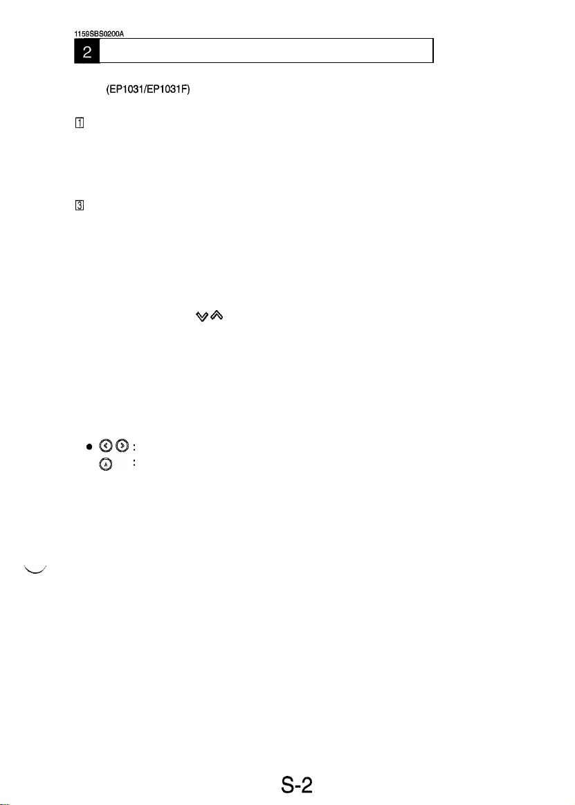
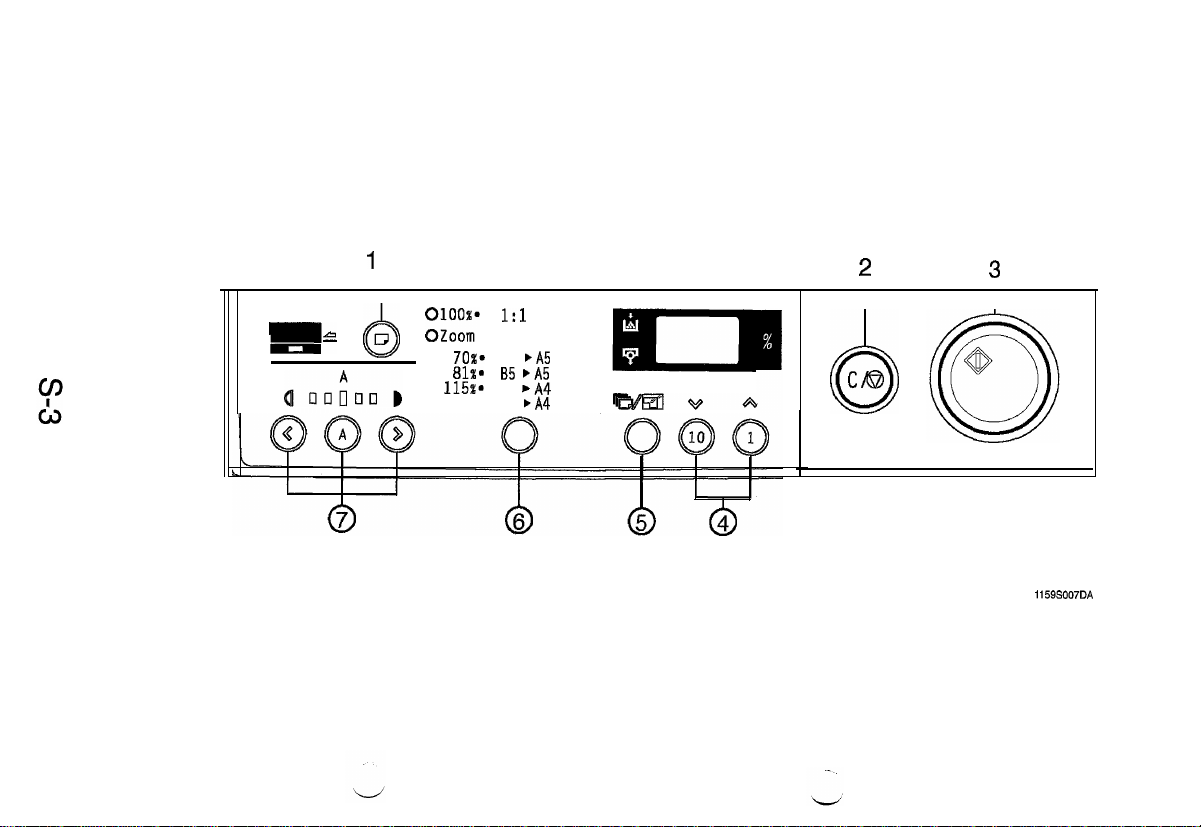
CONTROL PANEL KEYS AND INDICATORS
1
* For more details, see the Operators Manual shipped with the copier.
.
(EP1031/EP1031F)
Qj
Paper Source Key
l
Selects the paper source.
q
Clear/Stop Key
l
Returns the copy setting to one (1). Returns the zoom ratio to 100% and stops the copying operation.
I Start Key
l
Starts the copying operation.
q
Copy Quantity and Zoom Keys
l
Used to set the number of copies to be made and manual zoom settings. When used for setting the
number of copies, the number in the display panel will increase by one each time the one (1) key is
pressed and increase by ten each time the ten (10) key is pressed.
l
When used to set the zoom ratio, the number in the display panel will increase or decrease by one each
time the respective key
q
Copy Quantity/Zoom Selection Key
l
Switches the operation of the 1 and 10 keys between copy quantity and zoom functions.
++$- &
is pressed. The zoom range is from 64% to 156%.
I Fixed Zoom Ratio Key
l
Selects and displays a fixed zoom ratio setting.
q
Exposure Control Keys
0
l
:
Controls the density of the copy image.
:
For selecting the Auto Exposure/Manual Exposure Mode.
s-2
Page 5
1
Q
2
Q
3
Q
cs
&J :;::;
lil
70%*
A4
81%.
85 bA5
115%.
B5
141%. A5
bA5
,A4
bA4
64%-156%
TtbeirIVA
cm
0
0
1159S007DA
Page 6
*
For more details, see
.
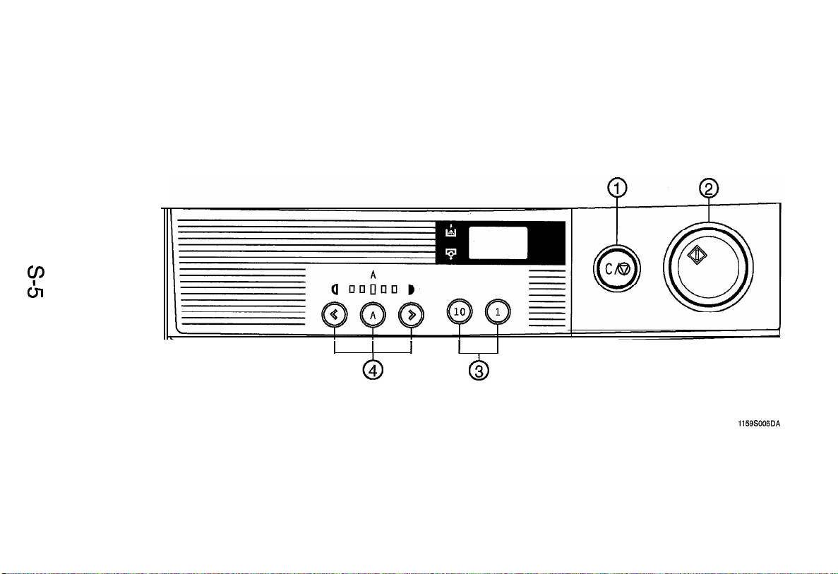
(EP1030/EP1030F)
q
Clear/Stop Key
l
Returns the copy setting to one (1). Stops the copying operation.
[ZI
Start Key
l
Starts the copying operation.
q
Copy Quantity Keys
l
Used to set the number of copies to be made. The number in the display panel will increase by one each
time the one (1) key is pressed and increase by ten each time the ten (10) key is pressed.
q
Exposure Control Keys
a
l
: Controls the density of the copy image.
:
For selecting the Auto Exposure/Manual Exposure Mode.
the Operators
Manual
s-4
Page 7
I
I
I I
1159S005DA
Page 8

1159SBS0400A
USER MODE
l
This mode is used to make various setting to the Users needs.
1159SBS0401A
4-l. Functions Available from the User Mode
No.
Ul
1159SBS0402A
Function
Auto clear ON/OFF
I
4-2. User Mode Setting Procedure
<Setting Procedure>
1. Holding down the Exposure Control Key@, turn ON the Power Switch. (Ul appears on the
Display Panel.)
2. Press the Start Key to show the data set the selected function.
3. Using the Copy Quantity and Zoom Keys, change the set data.
4. Press the Clear/Stop Key to validate the new setting. (The function no. reappears.)
<Resetting Procedure>
the User Mode.
l
Press the Clear/Stop
1159SBS0403A
49.
User Mode Setting Details
Function No.
Ul
to quit
Key
[User Mode]
Setting (The default is
<Auto
clear ON/OFF>
Select whether or not to activate the auto clear (panel reset) function after the
lapse of a given period of time after a copy cycle has been completed or a key
on the control panel has been
operated.
m
.)
S-6
Page 9

1159SBS0500A
SERVICE MODE
l
This mode is used by the Tech. Rep. to set, check, adjust, and/or program various service functions.
1159SBS0501
5-l. Service Mode Function Tree
A
d2 : Previous IU Counter count display
A0
:
Lens focal length correction
Al : Lens full size position correction
A2 : Feeding-direction zoom ratio correction
A3 : Full size registration adjustment
r
Adjust
1
A4 : Enlargement registration adjustment
A5 : Reduction registration adjustment
A8 : SDH registration adjustment
AA : Leading edge erase width adjustment
Ab : ATDC Sensor adjustment data
AC : Max. Exposure Lamp voltage adjustment data
-
F3 : Exposure Lamp Voltage Adjustment
F8 : ATDC Sensor Automatic Adjustment
F9
:
IU Check, Optimum Exposure Adjustment
1159SBS0502A
5-2.
Entering the Service Mode
<Setting Procedure>
1. Perform the following steps to set the copier in to Service Mode.
I)
Clear Stop Key ON
I)
Exposure Control Key @ ON
2. Select the Service Mode function using the Copy Quantity and Zoom Key @ and then press the Start
Key. (The functions are shown in the order of d, c, A, and F.)
<Leaving Service Mode>
l
Press the Clear/Stop Key twice to quit the Service Mode.
Exposure Control Key @ ON
e
Clear Stop
Key
ON
I)
s-7
Page 10

1159SBS0503A
5-3. Counter Display Procedure
<Display Procedure>
--t
1. Hold down the Clear/Stop Key for 3 sec.
2. Hold down the Clear/Stop Key for another 3 sec.
<Display Example>
The counter reading is shown on the Display Panel in the following order.
l
Total Counter
(Example : 1234)
The Total Counter count appears.
-+
The IU Counter or CP Counter appears.
The IlJ Counter count is displayed when
Note:
when 1 is set for
~2.
Vis
set for
c2and
CP Counter counter is displayed
S-8
Page 11

ii
59SBS0504A
5-4.
Setting in the Service Mode
1159SBS050401A
1. Display
l
This function tests for display of the warming-up time, current
IU
Counter, previous IU Counter, and the
control panel.
<Setting
Procedure>
1. Select the Display mode.
2. Select the function to be checked or set using the Copy Quantity and Zoom Key
(d0
appears on the Display Panel.)
@
and press the
Start Key.
3, Press the Clear/Stop Key to stop the display sequence.
<Leaving
the Function>
l
Select the next Display subfunction using the Copy Quantity and Zoom Key @or press the Clear/Stop
Key to quit the Display function,
[Service Mode b Display]
Display Function
d0
dl
d2
d3
Displays the warm-up time on the Display Panel.
<Current
Displays the count of the current IU Counter on the Display
Panel.
<Previous IU Counter count display>
Displays the count of the previous IU Counter on the Display
Panel.
Blinks all
LEDs
on the control panel other than the ready
indicator.
Setting
<Warm-up
time>
IU Counter count display>
<Display test>
:Display
Example>
The warm-up time and IU Counter count are shown on the Display Panel in the following order.
l
Warm-up time display
(Example : 46.50 sec.)
l
IU Counter count display
(Example : 12034)
S-9
Page 12

1159SBS050402A
2. Tech. Rep. Choice
l
This function allows the Tech. Rep. to make various settings and adjustments.
<Setting
Procedure>
1. Select the Tech. Rep. Choice function. (cl appears on the Display Panel.)
2. Select the subfunction to be set or adjusted using the Copy Quantity and Zoom Key
Start Key.
3. Change the set data as necessary using the Copy Quantity and Zoom Keys.
4. Press the Clear/Stop Key to validate the setting.
<Leaving the Function>
l
Select the next Tech. Rep. Choice subfunction using the Copy Quantity and Zoom Key @or press the
Clear/Stop Key to quit the Tech. Rep. Choice function.
[Service Mode b Tech. Rep. Choice]
Choice No.
The correct fixed zoom ratios and paper sizes are selected according to the
marketing area setting selected.
Setting (The default is
<Marketing area>
m
@
.)
and press the
c
c2
c3
di
Note:
Do not select
T
for this subfunction.
<IU
control mode>
Select whether to use the copier or Tech. Rep. to keep track of the replacement time of the IU.
>I
Note:
IU control : Controlled by
IU control = IU Counter; PM control = CP Counter
<Auto
Power OFF Disabling>
PM control : Not controlled
Select whether to enable or disable the Auto Power OFF that is to be acti-
vated after the lapse of a given period of time after a copy cycle has been
completed or a key pressed.
Data
Description
0 . . . . . . . . . . . . . . . . . . . .
0
min.
. . . . . . . . . . . . . .
m
. . . . . . . . . . . . . . . . . 12
30
min.
. . . . . . . . . . . . .
120
min.
s-10
Page 13

[Service Mode b Tech. Rep. Choice]
Select the ATDC control
T/C ratio 4.5%
le
T/C ratio 6.5%
T/C ratio 7.0%
I
s-11
Page 14

<Details of Data Cleared>
CP-related counters: Cleared only in
PA#
s-12
control mode.
ueareo
Page 15

1159SBS050403A
3. Adjust
l
This function allows the Tech. Rep. to set the correction values for making up for machine-to-machine
variations.
<Setting Procedure>
1. Select the Adjust function.
2. Select the subfunction to be set or adjusted using the Copy Quantity and Zoom Key
the Start Key.
3. Change the set data as necessary using the Copy Quantity and Zoom Keys.
4. Press the Clear/Stop Key to validate the setting.
<Leaving the Function>
l
Select the next Adjust subfunction using the Copy Quantity and Zoom Key
Key to quit the Adjust function.
(AO
appears on the Display Panel.)
@
and press
@
or press the Clear/Stop
[Service Mode b Adjust Mode]
Ad]ust
Mode
Corrects variations in the Lens focal length (according to the grouping of the
Lenses).
A0
Setting (The default is
<Lens focal length
m
correction>
.)
Al
A2
Corrects the zoom ratio in the crosswise direction by varying the Lens full size
position.
Data 33
Description
Corrects the zoom ratio in the feeding direction by varying the scan speed.
Data
Description
<Lens full size position correction>
. . . .
0
steps
43
-2.1%
. . . .
. . . .
. , . .
(Reduction
direction)
<Feeding-direction zoom ratio correction>
(Reduction
direction)
m .I..
17 steps
m
zkO%. . .
67
. . . .
38 steps
(Enlagement
direction)
. . . .
.
+2.1%
(Enlagement
direction)
57
I
s-13
Page 16

Adjust Mode
[Service Mode b Adjust Mode]
Setting (The default is
<Full size registration adjustment>
Corrects registration between the leading edge of the original and that of the
image in the full size made by varying the Synchronizing Roller start timing.
m
.)
A3
A4
A5
pi
Corrects registration between the leading edge of the original and that of the
image in an enlargement made by varying the Synchronizing Roller start
timing.
~1
Corrects registration between the leading edge of the original and that of the
image in a reduction made by varying the Synchronizing Roller start timing.
~~
Corrects registration between the leading edge of the original fed via the SDH
and that of the image by varying the SDH Registration Roller start timing.
<Enlargement registration adjustment>
<Reduction registration adjustment>
cSDH
registration adjustment>
s-14
Page 17

Adjust
Mode
AA
Ab
[Service Mode b Adjust Mode]
Setting (The default is
Corrects the leading edge erase width by varying the lmag Erae Lamp ON
timing.
Manually enter the setting value previously recorded when the starter has
been changed or the setting value data automatically set by an
cleared.
NOTE
Y
details, see
<Leading edge erase width adjustment>
<ATDC
Sensor adjustment data>
DWREASSEMBLY; ADJUSTMENT.
m
.)
F8
operation is
AC
Manually enter the setting value previously recorded if the max. Exposure
Lamp voltage adjustment data set by an F3 operation is cleared with Data
Clear of Tech. Rep. Choice.
For
r-
<Max. Exposure Lamp voltage adjustment data>
NOTE
details, see
DWREASSEMBLY; ADJUSTMENT.
s-15
Page 18

1159SBS050404A
4. Test
l
This function allows the Tech. Rep. to perform various functional test and adjustment.
<Setting Procedure>
1. Select the Test function.
2. Select the subfunction to be adjusted or checked using the Copy Quantity and Zoom Key @ and
press the Start Key.
<Leaving the Function>
l
Select the next Test subfunction using the Copy Quantity and Zoom Key @ or press the Clear/Stop
Key to quit the Test function.
(Fl
appears on the Display Panel.)
[Service Mode b Test]
Test No.
Fl
F2
F3
This test moves the paper through the copier for correct passage.
<Procedure>
1. Press the Start Key to start the sequence.
2. Press the Clear/Stop Key to stop the sequence.
Do not use this test as it is only for factory adjustment.
This test allows the Tech. Rep. to adjust the maximum Exposure Lamp
voltage and the optimum exposure setting in the Manual Exposure mode. (It
runs for 30 sec.)
NOTE
r details, see
<Exposure Lamp Voltage Adjustment>
DWREASSEMBLY;
Description
<Paper Passage Test>
<Corona output>
ADJUSTMENT.
F5
F8
F9
cAE
This test automatically adjusts the AE sensor. (It runs for 5 sec.)
NOTE
r details, see DWREASSEMBLY; ADJUSTMENT
This test automatically adjusts the ATDC sensor.
NOTE
r details, see
Do not use this test as it is only factory adjustment.
Sensor Automatic Adjustment>
cATDC Sensor Automatic Adjustment>
DWREASSEMBLY;
cIU Check, Optimum Exposure Adjustment>
ADJUSTMENT:
S-16
Page 19

[Service Mode b Test]
-
Components Energized in the Test
-
0 : Energized
-
:
Remain deenergized
s-17
Page 20

1159SSSO6OOA
0
If a part is replaced as part of troubleshooting and other service jobs, some parts require that a Test
operation be run and data values reentered and/or cleared.
01
02
0 : Required
(~6)
of Tech.
PWB-A
(*5)
I
0
1
I
Starter Exposure AE
IU
(3)
F3 (MAX)
F3
(Manual)
1
F5 (Auto)
F8
(ATDC)
Cleaning of CP-
related Counter
Make the adjustments in numerical order.
0
Clear the CP-related counter, select 2: CP-related counter in the Data Clear mode
*1:
Rep. Choice mode, then switch the power off/on.
When replacing the IU, F8 and CP-related counter are automatically cleared.
*2:
Including the replacement of the ATDC Sensor.
*3:
*4:
Including the Cleaning of Lamp Regulator and optical system.
When replacing PWB-A, if the EEPROM (IC3A) from the old PWB-A is installed on the new PWB-A,
*5:
these adjustments are not necessary.
Input the F3 setting on the factory label inside the front door.
*6:
*7:
Input the Ab setting on the factory label inside the front door.
(*I)
02 01
I
03 I 02
01
0(*2)
0(*2)
I I I
I
0
Lamp(*4)
01
02
1
I
Sensor Unit
I
0
I I
Power
I
P3)
1
(*7)
0
S-18
Page 21

MINOUA
Copyright
1997
MIIUOLTA
Printed in Japan
1
Use of this manual should
be strictly supervised to
avoid disclosure of
confidential information.
Co.,
Ltd
1
MINOLTA
CO,, LTDn
1159-7997-l 1 97074370
Printed in Japan
 Loading...