

Page 1

1159SBD000AA
EP1030/EP1030F
_EPlO3l/EPlO3lF
DE/REASSEMBLY,
ADJUSTMENT
,
L
MINODA
Page 2
1159Sl3DOOOOBA
+
For the Utmost safety
e
For replacement parts, use the genuine parts with their part numbers specified in the parts manual. Use
of a wrong part could cause an overload or dielectric breakdown resulting in an electric shock or fire.
l
Replace a blown fuse or thermal fuse with the corresponding genuine part with its part number specified
in the parts manual. Use of a fuse with a different rating or one with the same rating but of a
type can result in a fire.
Especially when a thermal fuse blows frequently, the thermal control system is probably faulty.
Be sure to take necessary action.
l
Before attempting to disassemble the machine, be sure to unplug its power cord. The machine contains
a hlgh voltage unif and a circuit with a large current capacity that may cause an electric shock or burn
from sparking.
The machine also contains quick moving parts, which could injure a person.
If the machine uses a laser, a person can lose his/her eyesight by a laser beam leak.
l
Wherever feasible, keep the covers and parts mounted when energizing the machine.
If it is absolutely necessary to energize the machine with its cover removed, do not touch an exposed
part that is being charged and use care not to allow your clothing to be caught by a timing belt, gear,
or other moving part.
l
Do not leave the machine unattended while it is being energized,
+
! Warning
A
*
differeni
! Caution
A
l
To actuate an interlock switch with a cover removed or opened, be sure to use the interlock switch actuating jig. Use of folded paper can damage the interlock switch mechanism.
Page 3
! Caution
A
l
A high voltage is being applied to the part marked with the symbol shown
on the right. Touching it can cause an electric shock. Be sure to unplug the
power cord when servicing this part or other parts near it.
l
When the machine is energized with any of its covers removed, never use a flammable spray near it,
as a fire can result,
l
Make sure that correct screws (diameter and length of the screw, binding/tapping screws) are used in
the correct places when assembling parts. If a wrong screw is used, a short insulating distance could
result. It could also result in collapsed threads, which provides only a poor grounding connection, resulting in an, electric shock,
l
A toothed washer and spring washer, if used originally, must be reinstalled. If they are left out, a contact
failure results causing an electric shock or fire,
l
Replace a lithium cell only with one having the part number specified in the parts manual. An explosion
could result if the cell is installed with wrong polarity or a wrong cell is installed.
Dispose of a used lithium cell according to the applicable local regulations. Never throw it away or abandon it on the users premises.
+
Other Precautions
l
While the machine is being energized, do not unplug or plug in a connector on a PWB or relay harness.
o
Since the Magnet Roller of the Imaging Unit generates a strong magneticforce, do not bring a CRT, watch,
floppy disk, or magnetic card near it.
l
Use of an air gun
parts to break down. Be sure therefore to use a blower brush or cloth to clean these parts. If a unit is to
be cleaned, be sure to remove the sensors in advance.
l
MCS
ICs
tions given in
l
The PC Drum is highly delicate. When handling the PC Drum, follow the precautions given in HANDLING
OF THE PC DRUM.
l
To reassemble, reverse the order of disassembly unless otherwise specified.
l
Note that replacement
or vacuum
are susceptible to static electricity. When handling a PWB loaded with
INSTRUCTIONS
+
generates static electricity which can cause the ATDC Sensor and associated
MOS ICs,
follow precau-
FOR HANDLING THE
of,a
PWB may call for readjustments or resetting of particular items.
PWBs
WITH MOS
ICs.
ii
Page 4
1159SBDOOOBA
CONTENTS
1
SERVICE INSTRUCTIONS
I-1, PRECAUTIONS FOR DISASSEMBLY/ADJUSTMENTS . . , , . . D-l
1-2. INSTRUCTIONS FOR HANDLING THE
WITH MOS
1-3. HANDLING OF THE PC DRUM. . . . . . . . . . . . . . . . . . . . . , . . . . D-3
1-4. PARTS WHICH MUST NOT BE TOUCHED . . . n . . e . . . . . . . . . D-5
2 DISASSEMBLY/REASSEMBLY
ICs . . , . . . . . . a . . m . . . . . . . . m n , . . . . . . . . . . . . . m . . .
PWBs
D-3
2-1. DOORS, COVERS,
IDENTIFICATION AND REMOVAL PROCEDURES.i
2-2. REMOVAL OF
2-3. PAPER TAKE-UP/TRANSPORT SECTIONS
Removal of the Paper Take-Up Roll and
(1)
Separator Roll Assy
Cleaning of the Paper Take-Up Rolls
(2)
Cleaning of the Separator Rolls
(3)
Removal of the Synchronizing Roller
(4
Cleaning of the Synchronizing Roller
(5)
Cleaning of the Multi Bypass Paper Take-Up Roller
(6)
2-4. OPTICAL SECTION
(1) Cleaning of the Original Grass
(2) Cleaning of the Scanner Rail and Bush
(3) Cleaning of the Exposure Lamp
(4) Removal of the Thermal Fuse
(5) Cleaning of the Ist, 2nd and 3rd Mirrors
.
(6) Cleaning of the Lens and 4th and 5th Mirrors
(7) Cleaning of the Cooling Fan Filter
(8) Removal of the Scanner Drive Motor M4
(9) Removal of the Scanner Drive Cable
(10) Winding of the Scanner Drive Cable
2-5. IMAGINGUNIT
(1) Removal of the Imaging Unit
(2) Replacement of the PC Drum
(3) Replacement of the Cleaning Blade
(4) Replacement of the Ds Positioning Collars
(5) Replacement of the Starter
(6) Cleaning of the Toner Antispill Mylar
(7) Cleaning of the Toner Satteing Prevention Mylar
(8) Cleaning of the Paper Dust Removal Cleaner
AND
EXTERIOR PARTS:
PWBs
...................................
. :
.............
..................................
....................
........................
....................
....................
....................................
.........................
..................
........................
..........................
................
.............
......................
................
....................
...................
.........................................
...........................
..........................
.....................
...............
............................
....................
.......
.......
..........
............
D-6
D-8
D-l 0
D-10
D-11
D-12
D-12
D-l 2
D-13
D-14
D-14
D-14
D-14
D-15
D-16
D-16
D-l 7
D-17
D-18
D-20
D-23
D-23
D-23
D-24
D-25
D-26
D-26
D-27
D-27
. . .
III
Page 5
CONTENTS
2-6. PC DRUM CHARGE CORONA AND
IMAGE TRANSFER/PAPER SEPARATOR CORONAS, . , . r , D-28
(1)
Removal of the PC Drum Charge Corona
(2) Cleaning of the Main Eraser
(3) Cleaning of the PC Drum Charge Corona Housing
(4) Cleaning of the Comb Electrode, Drum Charge Corona
(5) Cleaning of the PC
(6) Removal of the Image Transfer/Paper Separator
Coronas
(7) Cleaning of the Image Transfer/Paper Separator
Coronas Housing
(8) Cleaning of
(9) Cleaning of the Comb Electrode, Paper Separator
Corona
(IO) Cleaning of the Pre-Image Transfer Guide Plate
2-7.
FUSINGUNIT..................................~
(1) Removal of the Fusing Unit
(2) Cleaning of the Upper Fusing Roller
(3) Cleaning of the Fusing Paper Separator Fingers
(4) Cleaning of the Fusing Thermistor
(5) Cleaning of the
(6) Removal of the Lower Fusing Roller
(7) Cleaning of the Lower Fusing Roller
(8) Cleaning of the Fusing Unit Entrance Guide Plate
2-8. SDH UNIT
(1) Removing the Paper Feed Roller/Pick-up Roller/
Separator Roller
(2) Cleaning the Paper Feed Roller/Pick-up Roller
(3)
rCleaning
(4) Cleaning of the Upper Synchronizing Roller
(5) Cleaning of the Lower Synchronizing Roller . . r . . n . I , . . , . . D-37
(6) Cleaning the Upper Glass Roller
(7) Cleaning the Transport Roller
(8) Cleaning the Exit Roller
............................................
the
.............................................
(EP1030F/EP1031
of the Separator Roll
#Drum
.....................................
Image Transfer Charge Wire
<Fusing
......
...........................
Charge Corona Grid Mesh , . a . , . D-29
.............
Thermoswitch TSI
F Only)
..~.............IL~ ..........
.........................
.......................
..............
................................
................
. 1
*
..............
....................
THl...
.
i
.............
.1.............
....................
.......i............
.....................
...........
..............
...........
,
........
.
...........
.I.
....,..
.......
..........
.........
....
D-28
D-28
D-28
D-29
D-29
D-29
D-30
D-30
D-30
D-31
D-31
D-32
D-32
D-32
D-33
D-33
D-33
D-33
D-34
D-34
D-36
D-37
D-37
D-37
D-37
D-38
I
iv
Page 6

3 ADJUSTMENT
CONTENTS
3-l. JIGS AND TOOLS USED . . .
s
r
.
. . . .
a.. . n . . . . n t , , , , . , . m , . .
D-39
3-2. ADJUSTMENT REQUIREMENTS LIST . . . . , . , , . . , , , . . . , . . . D-40
3-3. ACCESSING THE TECH. REP. MODE . . . . m . , . . . . . . . . . . . . n D-41
3-4. ELECTRICAL/IMAGE ADJUSTMENTS . , . . , . . . . . , . . . . . m . , . D-42
(1) Adjustment of the Maximum Exposure Lamp Voltage for
the Manual Mode . . . . . . . . . . , . . . , . . . . . . . . . . , . . . . . . . . . . . D-42
(2) Adjustment of Optimum Exposure Setting in
Exposure Mode
(3)
Adj,ustment
....,.....,.....n....I
of Exposure Level in
the,+Auto
thee
Manual
1.1..3...,..~,.,
D-44
Exposure Mode . . . . . . . . . . . . . . . . . . . . . . . . . . . . . . . . . . . . . . D-46
(4) ATDC Adjustment . . . . . . . . . . . . . . . . . . . . . . . . . . . . . I . . . a . . D-47
(5) Adjustment of the Aperture Blades . . . . . . . . . . . . . . . , , . . . . . D-48
(6) Adjustment of Zoom Ratio in the Crosswise Direction
(EPl031/EP1031FOnly) nIIII I,..1. Ir.,..~I
(7) Adjustment of Zoom Ratio in the Feeding Direction
. . . . . . . . . . . D-49
. . . . . . .
D-51
(8) Adjustment of the Reference Position of
the Manual Bypass Table . . , . . . , n I . . . . . . . . . , _ . . . . . . . . . . D-53
(9) Adjustment of Paper Feed Cabinet
Reference Position , . . . . . . . . . . . . I . . . . . . . . , . . . . . . . . . . , . D-54
(IO) Adjustment of the Leading Edge Registration . . . . . I . . . . . D-55
@Leading Edge Registration in Full Size Mode , . . . I . . , , . D-55
*Leading Edge Registration in Enlargement Mode
(EP1031/EP1031Fonly)
@Leading
Edge Registration in Reduction Mode
(EP1031/EP1031Fon!y)
(11)
Adjustment of the Image Leading Edge Erase Width . . . . . D-61
(12) Adjustment of Edge Erase
. . . . . s . . .
,.. ..I..1L.. ._ ,,,. .
D-57
~~~~C~~~~~.~~sls~........... D-59
(EP1031/EP1031
F only) . . . . . . D-63
(13) Adjustment of SDH Reference Position
(EPI 03OF/EP1031
F Only) . . . . . n . . . . . . I . . . . . . . . . . . . . . . D-64
(14) Adjustment of SDH Leading Edge Registration
(EP1030F/EPi
031 F Only) . . . . . . . . . . . . . . . . . . . . . . . . . . . . D-65
(15) Adjustment of SDH Center Alignment
(EPI 030F/EP1031
3-5. OTHER ADJUSTMENT
(1)
Focus-Positioning of the Scanner and Mirrors
F Only) . . . . I . . . . . . . . . . . . . . . . . . . . . . , D-67
. . m . , . . . . . . . . . . , . . . . . . . . . . . . . . . . .
D-68
Carriage . . . . . . . . . . . . . . . . . . . . . . . . . . . . . . . . . . . . . . . . . . . . D-68
3-6. POWER SOURCE VOLTAGE
ROOT-MEAN-SQUARE-
VALUE-TO-MEAN-VALUE CONVERSION TABLE . , . . , . , . . . . D-69
Page 7
1139SSD0100A
SERVICE INSTRUCTIONS
1159SSD01OlA
l-l. PRECAUTIONS FOR DISASSEMBLY/ADJUSTMENTS
Observe the following precautions whenever servicing the copier.
l
Be sure to unplug the copier from the outlet before attempting to service the copier.
l
The basic rule is not to operate the copier anytime during disassembly.
If it is absolutely necessary to run the copier with its covers removed, use care not to allow your clothing
to be caught in revolving parts such as the timing belt and gears.
l
Be sure to use the Interlock Switch Actuating Jig whenever it is necessary to aotuate the Interlock Switch
with the covers left open or removed,
e
Do not plug in or unplug print jacks on the Board or connect or disconnect the Board connectors while
power is being supplied to the copier.
l
Do not use flammable spray around the copier in operation.
l
The Magnet Roller of the Imaging Unit generates strong magnetioforce. Do not bring it nearacathode-ray
tube or watch.
l
DQ not use an air gun or vacuum cleaner for cleaning the ATDC Sensor and
Cause
electrostatic destruction. Use a blower brush and cloth, If a unit containing these sensors is to be
cleaned, first remove the sensors from the unit.
l
When handling the
e
When handling the PC Drum, observe precautions given in Handling of the PC Drum.
e
Note that replacement of a PWB may call for readjustments or resetting of particular items.
l
Use the right screw in the right place at reassembly. Note that some are longer and some are thickerthan
PWBs
with MOS
ICs,
observe Instructions for Handling the
others.
l
A toothed washer is used with the screw that secures the ground wire to ensure positive conduction. Do
not forget to insert this washer at reassembly.
e
To reassemble the copier, reverse the order of disassembly unless otherwise specified.
l
If it becomes necessary to replace the thermal fuse or any other fuse mounted on a board, be sure to use
one of the rating marked on the blown fuse.
Always note the rating marked on the fuse, as the rating and mounting site or number used are subject
to change without notice.
l
Do not pull out the Toner Hopper while the Toner Bottle is turning, as a
or locking mechanism
If the copier is to be run with the Front Door swung down, make sure
csuld
result.
thatthe
position.
other sensors,
PWBs
damaged
Toner Replenishing Motor
as they can
with MOS
Toner Hopper is in the locked
ICs.
D-l
Page 8
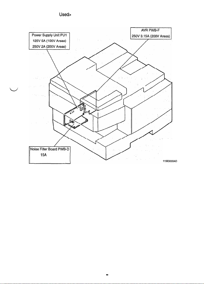
<List of Fuses
250V
15A
(1 OOV Areas)
250V 8A (200V Areas)
Usedr
1159D033AD
I
D2
Page 9
1139SBDOlOZA
1-2. INSTRUCTIONS FOR HANDLING THE
must be
The following precautions
Semiconductor)
ICs.
observed when handling
PWBs
WITH MOS
P.W.
Boards
ICs
with
MOS Oxide
During Transportation/Storage:
l
During transportation or when in storage, new P.W. Boards must not be indiscriminately removed from
their protective conductive bags.
l
Do not store or place P.W. Boards in a location exposed to direct sunlight.
l
When it becomes absolutely necessary to remove a Board from its conductive bag or case, always place
it on its conductive mat in an area as free as possible from static electricity.
l
Do not touch the pins of the
During
Replacement:
l
Before unplugging connectors from the P.W. Boards, make sure that the power cord has been unplugged
ICs
with your bare hands.
from the outlet.
l
When removing a Board from its conductive bag or conductive case, do not touch the pins of the
the printed pattern. Place it in position by holding only the edges of the Board,
l
Before plugging connectors into the Board, make sure that the power cord has been unplugged from the
I
ICs
or
power outlet.
During Inspection:
l
Avoid checking the IC directly with a multimeter; use connectors on the Board.
l
Never create a closed circuit across IC pins with a metal tool.
e
When it is absolutely necessary to touch the
ICs
and other electrical components on the Board, be sure
to ground your body.
1151SBD0103A
1-3. HANDLING
OF THE PC
DRUM
During Transportation/Storage:
l
Use the specified carton whenever moving or storing the PC Drum.
l
The storage temperature is in the range between -20C and
l
In summer, avoid leaving the PC Drum in a car for a long time.
+4OC.
Handling:
l
Ensure that the correct PC Drum is used.
l
Wheneverthe PC Drum has been removed from the copier, store it in its container or protect it with a Drum
Cloth.
l
The PC Drum exhibits greatest light fatigue after being exposed to strong light over an extended period
of time. Never, therefore, expose it to direct sunlight.
l
Use care not to contaminate the surface of the PC Drum with oil-base solvent, fingerprints, and other for-
eign matter.
l
Do not
saratch
l
Do not apply chemicals to the surface of the PC Drum.
l
Do not attempt to wipe clean the surface of the PC Drum.
the surface of the PC Drum.
D-3
Page 10
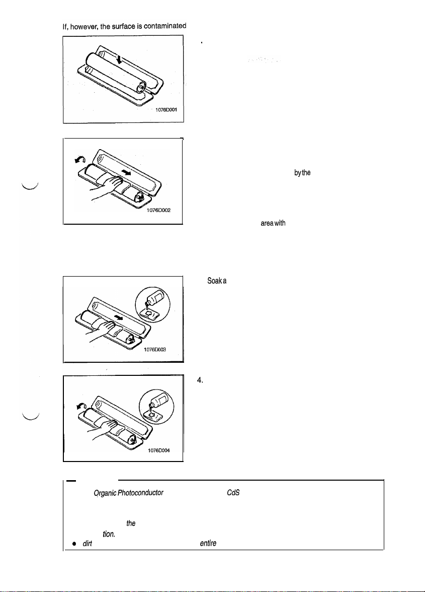
fingerprints, clean it using the following procedure.
with
.
Place the PC Drum into
1
2. Gently wipe the residual toner off the surface of the PC
one half of its container.
Drum with a dry, Dust-Free Cotton Pad,
a) Rotate the PC Drum so that the area of its surface on
which the line of toner left
bythe
Cleaning Blade is present is facing straight up. Wipe the surface in one continuous movement from the rear edge of the PC Drum to
the front edge and off the surface of the PC Drum.
b) Rotate the PC Drum slightly and wipe the newly ex-
posed surface
areawith
a CLEAN face of the Dust-Free
Cotton Pad. Repeat this procedure until the entire sur-
face of the PC Drum has been thoroughly cleaned.
* At this time, always use a CLEAN face of the dry Dust-Free
Cotton Pad until no toner is evident on the face of the Pad
after wiping.
3.
Soaka
small amount of either ethyl alcohol or isopropyl alcohol into a clean, unused Dust-Free Cotton Pad which
has been folded over into quarters. Now, wipe the surface
of the PC Drum in one continuous movement from its rear
edge to its front edge and off its surface one to two times.
* Never move the Pad back and forth.
Using the SAME face of the Pad, repeat the procedure ex-
4.
plained in the latter half of step 3 until the entire surface of
the PC Drum has been wiped. Always OVERLAP the
areas when wiping. Two complete turns of the PC Drum
would be appropriate for cleaning.
J
-
NOTES
l
The
Qrganic Photoconductor
Drum is softer than
CdS
and Selenium Drums and is therefore
susceptible to scratches.
l
Even when the PC Drum is only locally dirtied, wipe the entire surface.
l
Do not expose
illumina
a
If
dir/
remains after cleaning, repeat the
Uon.
fhe
PC Drum to direct sunlight. Clean it as quickly as possible even under interior
entire
procedure from the beginning one more time.
D-4
Page 11
1159SBD0104~
1-4. PARTS WHICH MUST NOT BE TOUCHED
(1) Screws
-
Purpose of Application of Red Paint
Red paint is applied to the screws which cannot be readjusted, set, or reinstalled in the field.
The basic rule is not to remove or loosen the screws to which red paint is applied. In addition, be advised
that, if two or more screws are designated as those which must not be touched on a single pat-t, only
one representative screw may be marked with red paint.
(2) Variable Resistors on Board
po
not turn the variable resistors on boards for which no adjusting instructions are given in
MEI+
ADJUST-
I
Page 12
1156SBD0200A
DISASSEMBLY/REASSEMBLY
1159SBD0201
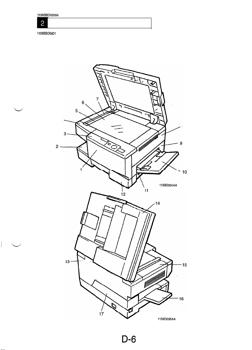
2-1. DOORS, COVERS, AND EXTERIOR PARTS: IDENTIFICATION AND
A
REMOVAL PROCEDURES
4
8
2-
1159D034AA
1159D035AA
Page 13
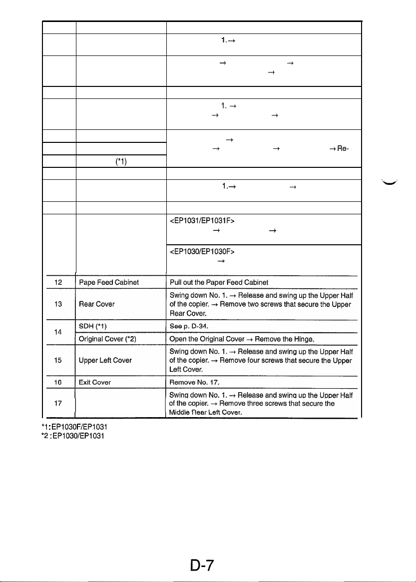
No.
1
2
3
4 Upper Front Left Cover
5
6
7 SDH Glass
8
9
10
11
Parts Name
Front Door
Middle Front Cover up the Upper Half of the copier. -I Remove two screws that
Control Panel Remove two screws that secure the Control Panel.
Original Scales
Original Glass
(*l)
Upper Right Cover
Middle Right Cover
Manual Bypass Table Remove two screws that secure the Manual Bypass Table.
Right Door
Swing down No.
move from the right side.
Pull out No. 12. -+ Swing down No. 1. + Release and swing
secure the Middle Front Cover.
Swing down No. 1. + Release and swing up the Upper Half
of the copier. -+ Remove No. 15. -I Remove two screws that
secure the Upper Front Left Cover.
Swing down No. 1. -I Release and swing up the Upper Half
of the copier. -I Remove No. 15. + Remove No. 4.
move two screws that secure the Original width Scales.
Remove two screws that secure the Upper Right Cover.
Swing down No. 1, -+ Remove No. 11. -I Remove two
screws that secure the Middle Right Cover.
<EP1031/EP1031F>
Open No. 11. -I Remove No. 9. -I Remove two screws that
secure the Right Door.
<EP1030/EP1030F>
Remove No. 9. + Remove two screws that secure the Right
Door.
Removal Procedure
1.
-t
Open Front door to the right and re-
--t Re-
*l
:
EP1030F/EP1031
*2
:
EP1030/EP1031
Middle Rear Left Cover
F only
only
D-7
Page 14
I
1159SBD0202A
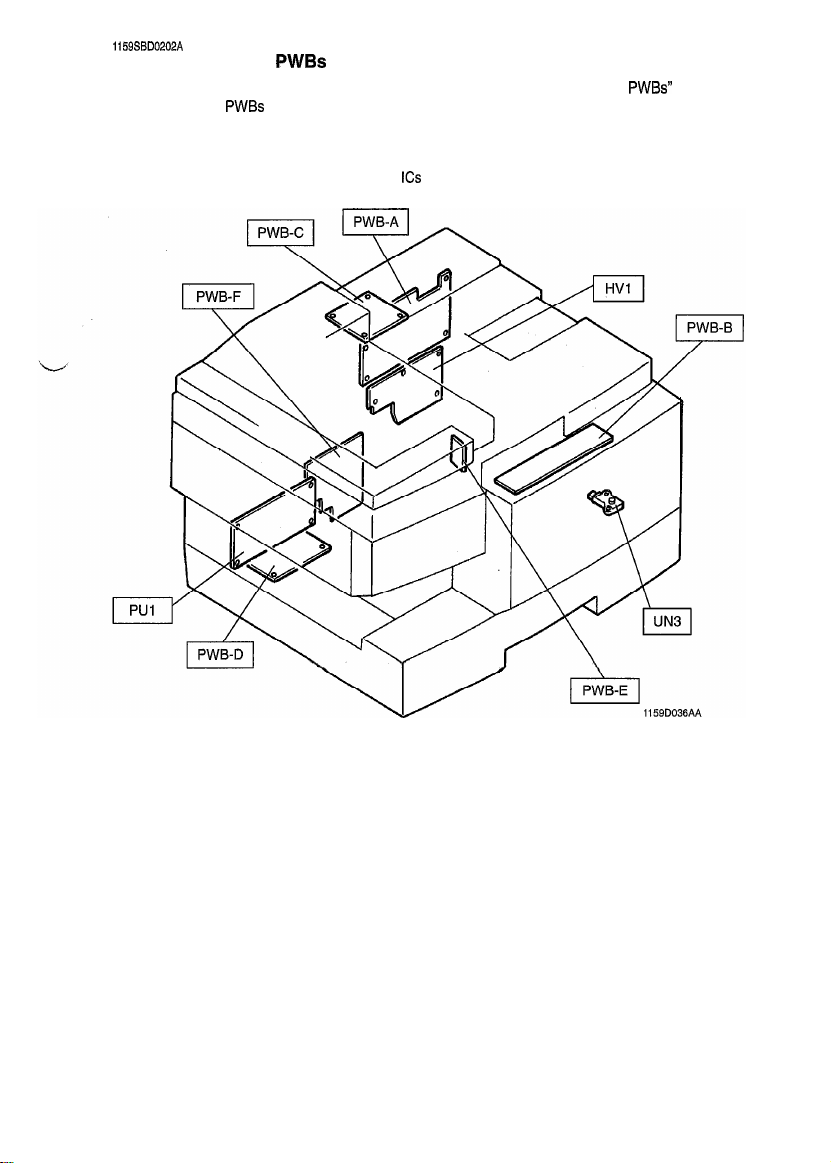
2-2. REMOVAL OF
l When removing a circuit board, refer to PRECAUTIONS FOR HANDLING THE
SWITCHES ON PWBs and follow the corresponding removal procedures given on the next page.
l
Replacement of a circuit board may call for readjustment or resetting of particular items.
l
The removal procedures given on the next page omit the removal of connectors and screws securing the
circuit board support or circuit board.
l
Where it is absolutely necessary to touch the
to ground your body.
PWBs
PWBs
contained in
ICs
and other electrical components on the board, be sure
D-8
Page 15
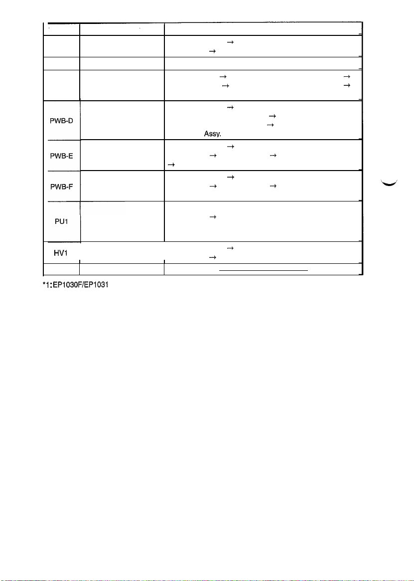
Symbol
r
PWB-A Master Board
PWB-B MSC Board
PWB-C SDH Board (1)
HVl
UN3
*l
:
EP1030F/EP1031
Parts Name
Noise Filter Board
AE Sensor Board
AVR
Power Supply Unit
Hight Voltage Unit
I
ATDC Sensor
F only
Removal Procedure
Swing down No. 1. + Release and swing up the Upper Half
of the copier. + Remove No. 13.
Remove No. 3.
Remove No. 14. -+ Remove the SDH Lower Rear Cover.
Remove the Mat. -I Remove the SDH Front Rear Cover.
Remove the SDH PWB Mountina Bracket Assv.
Swing down No. 1.
of the copier. -t Remove No. 17. + Remove the Power Sup-
ply Unit Mounting Bracket Assy. -I Remove the AVR Mounting Bracket Assy.
Swing down No. 1. + Release and swing up the Upper Half
of the copier. + Remove No. 15. -+ Remove No. 5, 6, and 7
4
Remove the AE Sensor Board Mounting Bracket Assy.
Swing down No. 1. + Release and swing up the Upper Half
of the copier.
Plate.
Swing down No. 1.4 Release and swing up the Upper Half
of the copier. 4 Remove No. 17.
NOTE: Never replace individual parts within the Power Supply
when repairing it. Always replace the entire Power Supply Unit.
Swing down No. 1. -I Release and swing up the Upper Half
of the copier. 4 Remove No. 13.
I
--t
Release and swing up the Upper Half
--f
Remove No. 17. + Remove the Contact
--t
+
D-9
Page 16
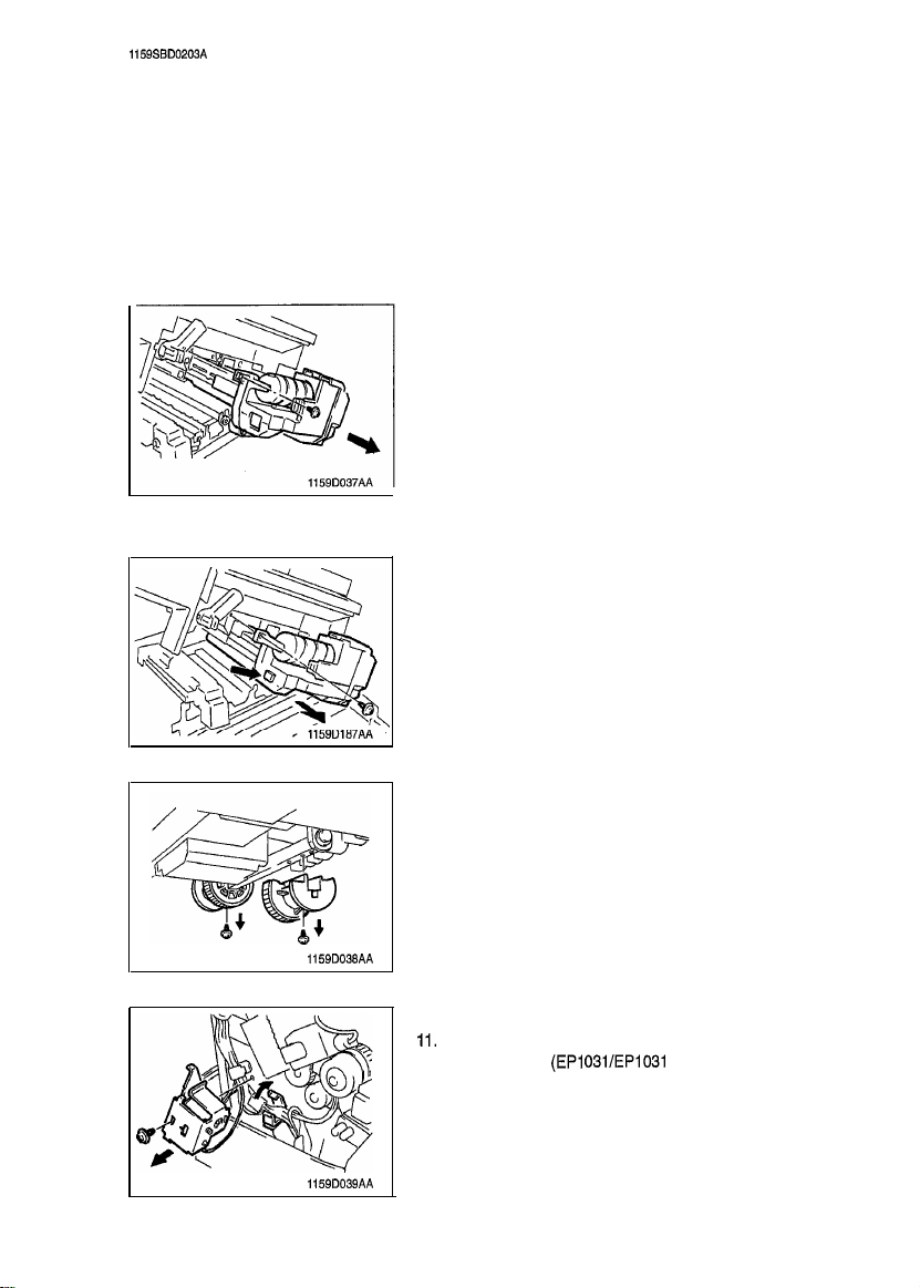
1159SBD0203A
~
2-3. PAPER TAKE-UP/TRANSPORT SECTION
(1) Removal of the Paper Take-Up Roll and Separator Roll Assy
Remove two screws and the Upper Right Cover.
1.
2.
Remove two screws and the Middle Right Cover.
3.
Remove one screw and the Right Door.
4.
Pull out the Paper Feed Cabinet.
5.
Swing down the Front Door.
6.
Release and swing up the Upper Half of the copier.
7.
Remove three screws and the Rear Cover.
<USA, Canada>
8.
Remove one screw and the Imaging Unit from the copier.
<Except USA, Canada>
8.
Push the lock lever and remove the IU.
1159D038AA
1159D039AA
9.
Remove each of the two screws and the Paper Take-Up
Roller.
10. Open the Cord Clamp.
11.
Remove one screw and the Multi Bypass Paper Take-Up
Solenoid Assy.
(EPI
03VEP1031 F Only)
D-10
Page 17
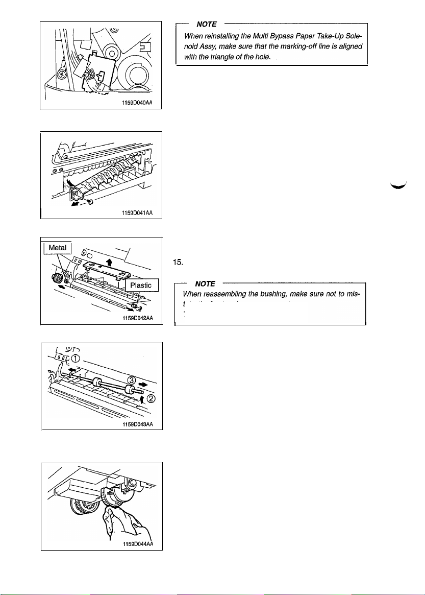
1159D040AA
12. Remove one screw and the Gide Plate.
I
1159D041AA
1159D042AA
1159D043AA
13. Remove the Separator Roller Guide Plate.
14. Remove the Rear Gear.
Snap off the one E-ring to remove the front and rear Bush-
15.
ings.
take the front and rear components.
The front is plastic and the rear is metal.
I
Move the Separator Roller to the rear and, as shown in by
16.
the sequence in the illustration to the left, remove it from
the front.
(2) Cleaning of the Paper Take-Up Rolls
Pull out the Paper Feed Cabinet.
1.
Using a soft cloth dampened with alcohol, wipe clean the
2.
two Paper Take-Up Rolls.
I
1159D044AiI
D-11
Page 18
,
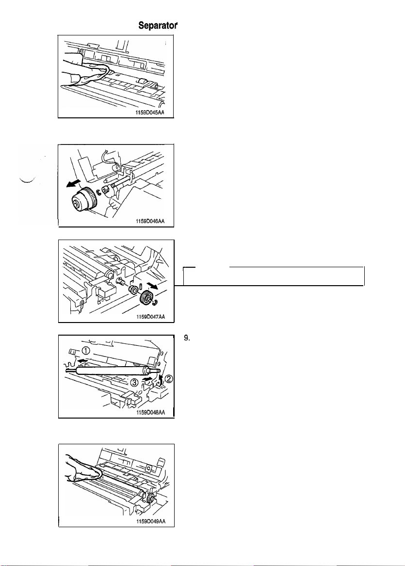
(3) Cleaning of the
Separator
1159D045AA
Rolls
1.
Swing down the Front Door.
Release and swing up the Upper Half of the copier.
2.
Remove one screw and the Imaging Unit from the copier.
3.
Using a soft cloth dampened with alcohol, wipe clean the
4.
two Separator Rolls.
(4) Removal of the Synchronizing Roller
1.
Swing down the Front Door.
2.
Release and swing up the Upper Half of the copier.
Remove the Imaging Unit from the copier.
3.
Remove three screws and the Rear Cover,
4.
Snap off the one E-ring to remove the Timing Clutch.
5.
Snap off the one E-ring to remove the Rear Bushing.
6.
1159D046AA
Snap off the one E-ring to remove the Gear.
7.
8.
Remove the front Bushing.
I
NOTE
Use care not to loose the Set Pin when removing the Gear.
116QD047AA
I
n
3.
Move the Timing Roller to the rear and, as shown in the illustration to the left, remove it from the front.
1159D048AA 1
(5) Cleaning of the Synchronizing Roller
Swing down the Front Door.
1.
Release and swing up the Upper Half of the copier.
2.
Using a soft cloth dampened with alcohol, wipe clean the
3.
Synchronizing Roller.
I
1159D049AA
D-12
Page 19
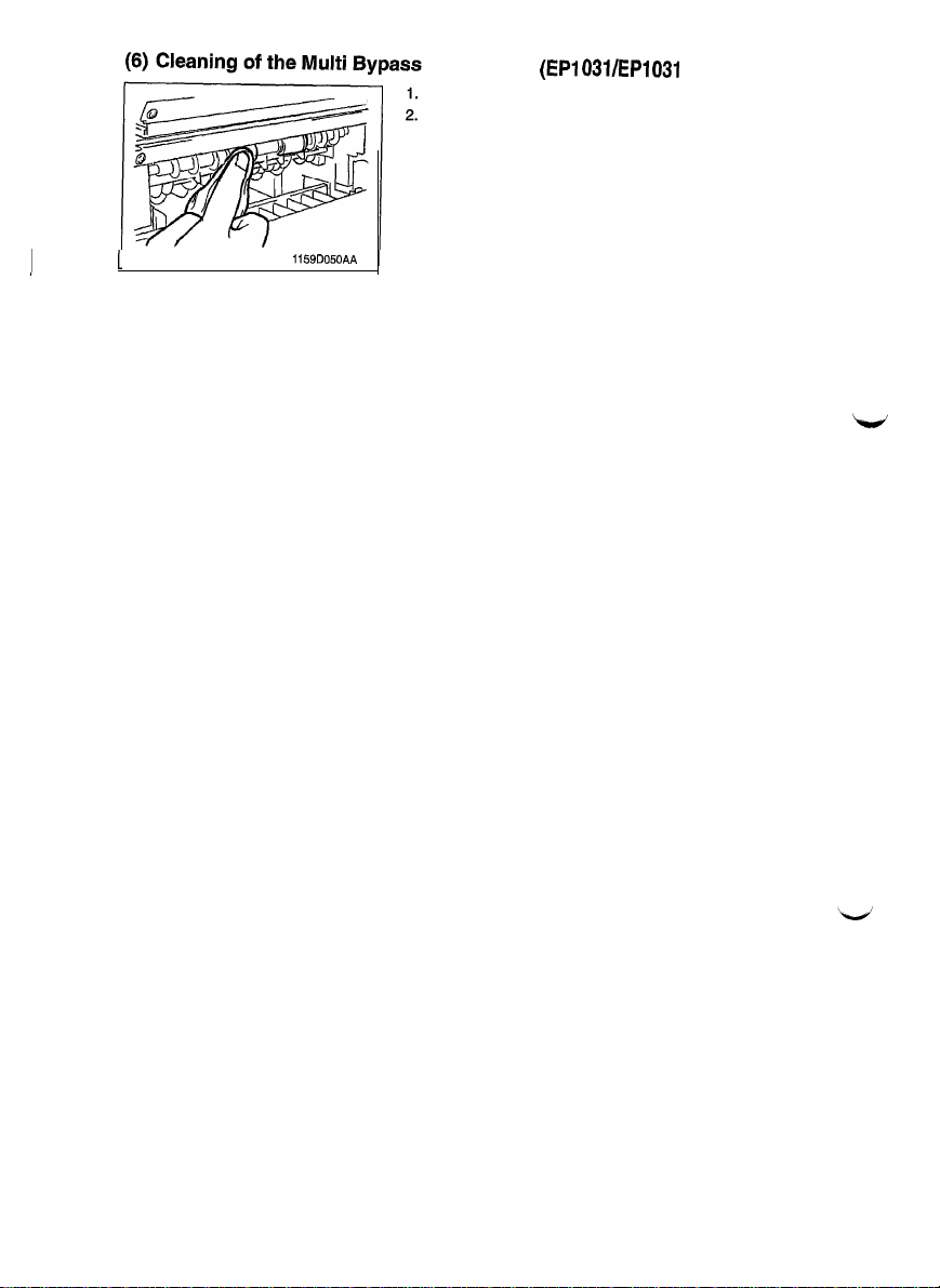
Feed Roller (EPI
Open the Right Door.
Using a soft cloth dampened with alcohol, wipe clean
two Multi Bypass Paper Feed Rollers.
031/EP1031
F Only)
the
I
1
1159D050AA
D-13
Page 20
1159SBD0204A
2-4. OPTICAL SECTION
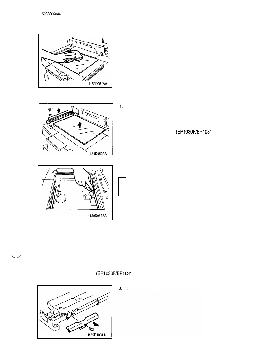
(1) Cleaning of the Original Grass
1.
1159D051AA
Wipe clean the Original Glass with a soft cloth.
(2) Cleaning of the Scanner
Rail and Bush
1.
Swing down the Front Door.
2.
Release and swing up the Upper Half of the copier.
3.
Remove four screws and the Upper Left Cover.
4.
Remove two screws and the Original Width Scale.
5.
Remove the SDH Glass. (EP1030F/EP1031 F Only)
6.
Remove the Original Glass.
7.
Wipe clean the Scanner Rail and Bush with a soft cloth.
-
NOTE
Be
Brush have been cleaned.
(3) Cleaning of the Exposure Lamp
1.
Swing down the Front Door.
2.
Release and swing up the Upper Half of the copier.
3.
Remove four screws and the Upper Left Cover.
4.
Remove one screw and the Upper Front Left Cover.
5.
Swing down and lock the Upper Half of the copier.
6.
Remove two screws and the Original Width Scale.
7.
Remove the SDH Glass. (EP1030F/EP1031 F Only)
8.
Remove the Original Glass.
Remove one screw and front terminal cover.
sure to apply lubricating oil after the Scanner Rail and
1159D198AA
D-14
Page 21
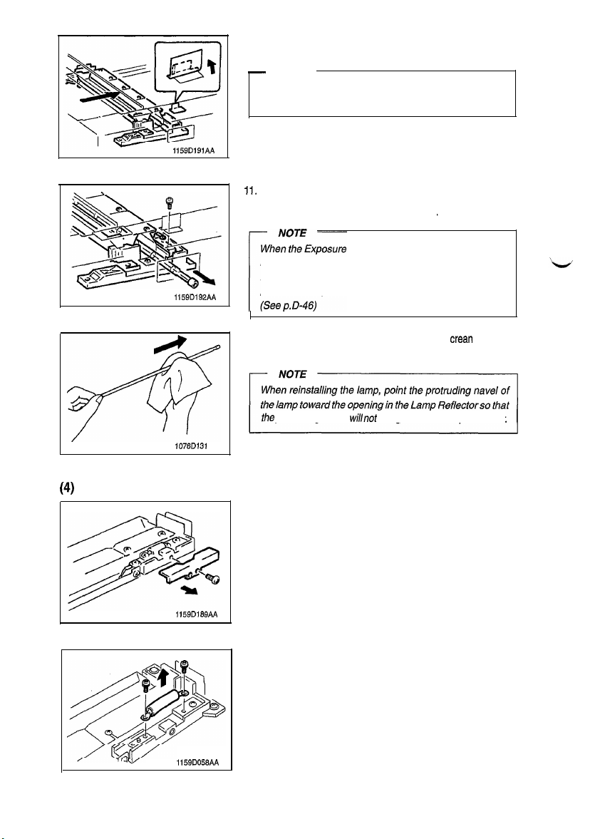
1159D192AA
10. Move the Scanner to the position shown on the left and
peel the seal partly off the copier frame.
-
NOTE
Do not peel the seal completely off the frame.
cleaning steps have been completed, affix it back again.
Remove one screw and front Scanner Harness.
11.
Remove one screw and the Exposure Lamp Terminal.
12.
13.
Slide out the Exposure Lamp.
Lamp has been cleaned or replaced,
be sure to make the adjustment ofopfimum exposure setting in the Manual Exposure mode. (Seep. D-44) and ad-
justment of exposure Level in the Auto Exposure mode.
After the
1076D131
(4)
Removal of the Thermal Fuse
1159D169AA
I
Using a soft cloth dampened with alcohol,
14.
by gently wiping its surface in one direction.
the
protruding
1.
Remove one screw and rear terminal cover.
Remove two screws and the Thermal Fuse.
2.
navel willnot hit
against
the Lamp Reflector.
crean
the lamp
1159D056AA
D-15
Page 22
I
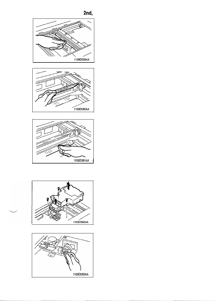
(5) Cleaning of the Ist,
2nd,
1159D059AA
1159D060AA
1159D061AA (
and 3rd Mirrors
1.
Wipe clean the 1st Mirror with a soft cloth.
2.
Wipe clean the 2nd Mirror with a soft cloth.
3.
Wipe clean the 3rd Mirror with a soft cloth.
(6) Cleaning of the Lens and 4th and 5th Mirrors
1.
Remove the Original Glass.
2.
Remove two screws and the Optical Cover.
3.
Remove two screws and the Lens Cover.
4.
Gently dust off the surface of the Lens using a soft cloth.
1159D063AA
D-l 6
Page 23
5.
Wipe clean the 4th and 5th Mirrors with a soft cloth.
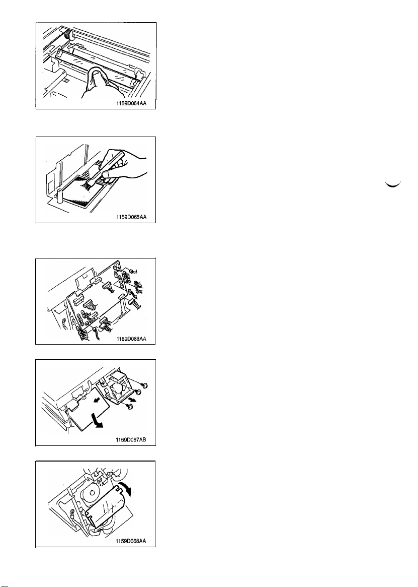
1159D064AA
(7) Cleaning of the Cooling Fan Filter
1.
Swing down the Front Door.
2.
Release and swing up the Upper Half ofthe copier.
3.
Remove three screws and the Rear Cover.
4.
Clean the Cooling Fan Filter using a brush or a vacuum
cleaner.
1159D065AA
(8) Removal Scanner Drive Motor M4
1.
Remove the Upper Right Cover.
2.
Swing down the Front Door.
3.
Release and swing up the Upper Half of the copier.
4.
Remove three screws and the Rear Cover.
5.
Remove the 17 connectors from the PWB-A.
1159D067AB
1159D068AA
6.
Remove the PWB-A.
7.
Remove the three screws and the Ozone Fan Motor Assy.
8.
Free the Mylar.
D-17
Page 24
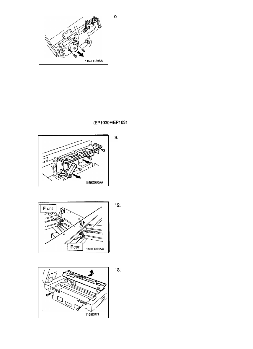
9.
Remove the Harness for the Scanner Drive Motor
Locking Edge Cover and remove it from the Cord Clamp.
10.
Remove two screws and the Scanner Drive Motor M4.
1159D069AA
(9) Removal of the Scanner Drive Cable
Swing down the Front Door.
1.
Release and swing up the Upper Half of the copier.
2.
3.
Remove the Imaging Unit from the copier.
4.
Remove the Upper Left Cover, Upper Front Left Cover and Rear Cover.
Swing down and lock the Upper Half of the copier.
5.
Remove the Original Scale and Original Glass.
6.
Remove the SDH Glass. (EP1030F/EP1031 F Only)
7.
a.
Remove the Upper Right Cover.
Remove the two screws and one connector and the Control Panel.
Remove the one screw and the Upper Unit Release Lever.
10.
11.
Remove the three screws and the Lower Panel Cover.
1159D070AA 1
from
the
1159DO71 AA
Move the Scanner to the center and remove the one screw
and the front and rear Scanner Mounting Brackets.
Remove the two screws and the Optical Section Cooling
Duct.
D-18
Page 25

1159D073AA
I
NOTE
When reassembling the Optical Section Cooling Duct,
make sure
lus
14.
Remove two screws and the Optical Cover.
15.
the Rear Wire is retained as
tra tion.
Unhook each of the two springs at the front and rear and
remove the cable.
shown in the
il-
I
I i
1159D075AC
1159D076AC
16.
Snap off the one E-ring from the Pulley Shaft.
17.
Remove the one screw from the Drive Belt Pulley.
18.
Remove each screw from the front and rear Cable Drive
Pulleys.
19. Remove the Pulley Shaft.
20. Remove the Cable Drive Pulley.
D-l
9
Page 26

(10) Winding of the Scanner Drive Cable
+
Remark
WheneverScanner Drive Cable has been rewound, be sure to make theAdjustment of the Scanner/Mirrors
Carriage Position. See p.D-67.
1159D077AA
1.
From the bead on the rear pulley, wrap the shorter of the
Cable counterclockwise four times towards the rear.
I
1159D07BAA 1
1159D079AC
1159D080AA
N
2.
Wrap the longer of the Cable clockwise three times to-
wards the front and secure with the Tape.
3.
From the bead on the front pulley, wrap the longer of the
Cable in clockwise three times towards the front.
D-20
Page 27

/.
/
9
1159D081AC
1159D082AC
1159DOMAA 1
4.
Wrap the shorter of the Cable in counterclockwise four
times towards the rear and secure with the Tape.
Mount the front and rear Cable Drive Pulleys, Drive Belt
5.
Pulley and Pulley Shaft.
6.
Install the three set screws to the front and rear Cable
Drive Pulleys and the Drive Belt Pulley and mount the one
E-ring to the Pulley Shaft.
Wrap the shorter of the two Cable in the rear around
7.
Pulley B and secure it to the frame.
1159D084AA
1159D085AA
8.
Pull the longer of the two Cable and wrap it around
Pulleys A and B.
9.
Wrap the shorter of the two Cable in the front around
Pulley B and secure it to the frame.
D-21
Page 28

1159D097AA
10.
Pull the longer of the two Cable and wrap it around Pulleys
A and B.
l The longer Cable is wrapped around the outside of
Pulley B.
l
The shorter Cable is wrapped around the inside of Pulley
B.
1159D089AA
I
NOTE
Set the Rounded Tip as shown in the illustration to the left.
r
11.
Set the front and rear Cable in the groove for the Cable
Guide and attach to the Spring.
12.
Peel tape
13.
Secure the Optical Cover with two screws.
cuff
the Cable Drive Pulleys.
1159D196AA
D-22
Page 29

1159SSD0205A
2-5.
IMAGING UNIT
(1) Removal of the Imaging Unit
1.
2.
<USA,
Canada>
3.
Swing down the Front Door.
Release and swing up the Upper Half of the copier.
Remove one screw and the Imaging Unit from the copier.
<Exceet
USA, Canada>
3.
(2) Replacement of the PC Drum
1.
1159D090AB
2.
3.
I
1159DOQlAB
Push the lock lever and remove the
Remove the two Covers.
Remove the Connectors for the Ground-Shielded Harness.
Remove the Drum Charge Corona.
IU.
D-23
Page 30

Remove the three screws and the Hopper Unit.
4.
Remove two shoulder screws and the Cleaning Blade.
5.
Turn the Bushing in the direction of the arrow and remove.
6.
Push in on the rear
7.
and replace it.
=Y/
1159D096AA
(3) Replacement of the Cleaning Blade
Remove the two Covers.
1.
1159DOQOAB
D-24
of
the PC Drum, remove
it
from
the front
Page 31

1159D091AB
1159D092AC 1
2.
Remove the Ground-Shielded Harness Connector.
3.
Remove the Drum Charge Corona.
4.
Remove the three screws and the Hopper Unit.
5.
Remove and replace the Cleaning Blade.
(4) Replacement of the Ds Positioning Collars
Remove the three screws and the Hopper Unit.
1.
1159D093AA
Remove the one screw and the Recycling Pipe.
2.
D-25
Page 32

1159D190AA
Snap off the two E-rings to remove the one screw and the
3.
Drive Gear.
Remove the front Ds Positioning Collar and replace.
4.
NOTE
When replacing the front Ds Positioning Collar, hold the
shaft behind the Bucket Roller.
r
Snap off the one E-ring to remove the rear Ds Positioning
5.
Collar and replace.
(5) Replacement of the Starter
1159D165AA
1.
Damp the developer out of the Developing Unit.
2.
Set the Starter Bottle to IU and perform adjustment of
the F8 ATDC Adjustment. (See
p.D-46)
D-26
Page 33

3.
Remove the Starter Bottle and set the Toner Bottle.
NOTE
Shake the Toner Bottle before setting it in place.
r
1159DlWAA
(6) Cleaning of the Toner Antispill Mylar
1.
Remove the two screws, the Receiver Plate and the
Toner Antispill Mylar.
2.
Using a brush, whisk dust off the Toner Antispill Mylar.
11590166AB
(7) Cleaning of the Toner Scattering Prevention Mylar
1.
Using a brush, whisk dust off the Toner Scattering Prevention Mylar.
1159Dl69AA
(6) Cleaning of the Paper Dust Removal Cleaner
I.
Remove the Timing Roller.
2.
Using a brush, wihisk dust off the Paper Dust Removal
Cleaner.
D-27
Page 34

2-6. PC DRUM CHARGE CORONA AND IMAGE TRANSFER/
PAPER SEPARATOR CORONAS
(1) Removal of the PC Drum Charge Corona
1.
Remove the two Covers.
1159D090AB
2.
Remove the Ground-Shielded Harness Connector.
3.
Remove the Drum Charge Corona.
1159DO91 AB
(2) Cleaning of the Main Eraser
1.
Using a soft cloth dampened with alcohol, clean the Main
Eraser by gently wiping its surface in one direction.
1159D200AA
(3) Cleaning of the PC Drum Charge Corona Housing
1.
Press the Mesh Holder on the front of the Corona Unit in
the direction of arrow to remove the Grid Mesh.
1159D172AB
2
1159D173AB 1
2.
Remove the End CUDS from the front and rear end of the
Unit.
D-28
Page 35

I
[
3.
Remove the Comb Electrode, Drum charge Corona.
-
NOTE
Use care not to deform the Electrode. When removing it,
first snap off its spring end.
/
1159D174AB
(4) Cleaning of the Comb Electrode, Drum charge Corona
1.
Use a blower brush to clean the Comb Electrode, Drum
charge Corona.
-
NOTE
If
the blower brush is not effective in cleaning the Comb
Electrode, Drum Charge Corona use a soft cloth dampened with alcohol to clean serious contamination.
I
I
1159D175AA
(5) Cleaning of the PC Drum charge Corona Grid Mesh
Blow all foreign matter off the Grid Mesh a blower brush.
tamination.
1159D176AA 1
(6) Removal of the Image Transfer/Paper Separator Coronas
1.
Swing down the Front Door.
2.
Release and swing up the Upper Half of the copier.
3.
Pull out the Image Transfer/Paper Separator Coronas.
1159D177AA
(7) Cleaning of the Image Transfer/Paper Separator Coronas Housing
1.
Remove the Image Transfer/Paper Separator Corona
Housing,
1159D178AA
D-29
Page 36

2.
Using a soft cloth dampened with alcohol, wipe the housing clean of dirt.
11590179AA
(8) Cleaning of the Image Transfer Charge Wire
1.
Clamp a soft cloth (gauze) dampened with alcohol with
tweezers and clean the Charge Wire in one direction.
Wipe from the Hook side to the Spring side.
1159D180AA
(9) Cleaning of the Comb Electrode, Paper Separator Corona
1.
Use a blower brush to clean the Comb Electrode, Paper
Separator Corona.
(10) Cleaning of the Pre-Image Transfer Guide Plate
1.
Use a soft cloth dampened with alcohol to clean the
Image Transfer Guide Plate.
D-30
Pre-
Page 37

1159SBD0207A
2-7. FUSING UNIT
(1) Removal of the Fusing Unit
1.
2.
3.
4.
5.
1159D097AB
6.
7.
Swing down the Front Door.
Release and swing up the Upper Half of the copier.
Removal three screws and the Middle Rear Left Cover.
Remove the Harness for the Fusing Unit from the Edge
Cover and remove it from the Cord Clamp.
Remove the two terminals for the Fusing Unit.
Remove the one screw, two washers and Ground Wire
from the Fusing Unit.
Remove the one Shoulder Screw, turn the Fusing Unit in
the direction of the arrow and remove it.
1159DlOlAA
Remove one screw and the Bracket.
8.
Remove the three screws and the Cover for the Fusing
9.
Unit.
10.
Remove the one screw and front Heater Harness.
11.
Remove two screws and the Fusing Thermoswitch.
12. Remove one screw and the Fusing Thermistors.
D-31
Page 38

13.
Remove the two screws and the front Power Supply Brush
Assy.
Remove the two screws and the rear Power Supply Brush
14.
Assy.
1159D102AB
15. Remove two C-clips.
16. Remove one Spur Gear.
Remove the front and rear Bushings and remove the Roll-
17.
er.
1159D103AB
(2) Cleaning of the Upper Fusing Roller
Using a soft cloth dampened with alcohol or silicone oil,
1.
wipe clean the Upper Fusing Roller.
1159D104AA
1
(3) Cleaning of the Fusing Paper Separator Fingers
Using a soft cloth dampened with alcohol or silicone oil,
1.
wipe clean the Fusing Paper Separator Fingers.
1159D105AA
(4) Cleaning of the Fusing Thermistor
1159D106AA
1
THl
Using a soft cloth dampened with alcohol or silicone oil,
1.
wipe clean the Fusing Thermistor
D-32
THl.
Page 39

~
(5) Cleaning of the Fusing Thermoswitch TSI
Using a soft cloth dampened with alcohol or silicone oil,
1.
wipe clean the Fusing Thermoswitch
TSl.
I
1159D107AA
(6) Removal of the Lower Fusing Roller
1.
Remove the one screw and one washer, Lift the Fusing Entrance Guide in the direction of the arrow and remove.
Y
11~9D108AA
1159D133M
1.
Remove the Fusing Unit.
2.
Using a soft cloth dampened with alcohol, wipe clean the
Fusing Unit Entrance Guide Plate.
D-33
Page 40

1159SBD020SA
2-8. SDH Unit
(EP1030F/EP1031
F Only)
(1) Removing the Paper Feed Roller/Pick-up Roller/Separator Roller
1.
Swing down the Front Cover.
2.
Release and swing up the Upper Half of the copier.
3.
Remove three screws and the Rear Cover.
4.
Remove the one Connector from the PWB-A.
5.
Remove the one screw, one washer and the Ground Wire.
1159D111AB
Open the SDH and remove the one screw, one washer and
the Ground Wire.
11590112AC (
1 7.
Remove the six screws and SDH.
I
1159D113AB
8.
Remove the two screws and Lower Rear SDH Cover.
-
NOTE
The SDH, left attached to the copier, can also be
clisas-
sembled.
1159D114AA
9.
Remove the three screws and Lower Front SDH Cover.
D-34
Page 41

1159D118AB
10. Remove the Harness.
11. Remove the four screws and the Transport Guide Plate
Assy.
12. Remove the three Collars and the Harness.
13.
Remove the three screws and free the PWB-C Assy.
14.
Remove the two screws and free the Lead Switch Assy.
15.
Remove the eight screws and the Transport Assy.
. \
1159D119AB
1159Dl
ZOAA
16.
Move the Bushing to the rear and remove the Paper Roller
Assy.
17.
Snap off the one E-ring to remove the Paper Feed Holder
Assy.
D-35
Page 42

1159D122AA
1159D123AA
1159D124AA
Snap off the one E-ring to remove the Paper Feed Roller
18.
Assy.
Snap off the one E-ring to remove the Pick-up Roller from
19.
the Paper Feed Holder Assy.
20.
Remove the Separator Holder and Spring from the Transport Guide Plate.
21. Snap off the one E-ring to
Assy.
(2) Cleaning the Paper Feed Roller/Pick-up Roller
1.
Remove the Paper Feed Roller/Pick-up Roller.
Using a soft cloth dampened with alcohol, wipe clean the
2.
Rollers.
1159D126AA
D-36
remcve
the Separator Roller
Page 43

(3) Cleaning of the Separator Roll
Remove the Separator Roller Assy.
1.
Using a soft cloth dampened with alcohol, wipe clean the
2.
Separator Roil.
(4) Cleaning of the Upper
I
1159D128AA
nchronizing Roller
s1
Open the
Using a soft cloth dampened with alcohol, wipe clean the
Upper Synchronizing Roller.
OpeningKioseing
(5) Cleaning of the Lower Synchronizing Roller
Remove the Transport Assy.
1.
2.
Using a soft cloth dampened with alcohol, wipe clean the
Lower Synchronizing Roller.
1159D129AA 1
(6)
Cleaning the Upper Glass Roller
Remove the Transport Assy.
1.
Using a soft cloth dampened with alcohol, wipe clean the
2.
Upper Glass Roller.
Guide
.
1159D130AA
(7) Cleaning the Transport Roller
Remove the Transport Assy.
1.
Using a soft cloth dampened with alcohol, wipe clean the
2.
Transport Roller.
1159D132AA
Page 44

(8) Cleaning the Exit Roller
1159D131AA
.
1.
Using a soft cloth dampened with alcohol, wipe clean the
Exit Roller.
D-38
Page 45

1156SSD0300A
ADJUSTMENT
1159SBD0301A
3-1. JIGS AND TOOLS USED
+
Important
l
These jigs are used when adjusting the Scanner for correct positioning.
DScanner Adjusting jig (Front)
1159D196AS
@Scanner Adjusting jig (Rear)
I
1159D197AB
D-39
Page 46

1159SBD0302A
3-2. ADJUSTMENT REQUIREMENTS LIST
Adjustment of Optimum
Setting in the Manual
Adjustment of Zoom
Adjustment of
ing Edge Registration in Full
Adjustment of
Exposure
Exposure
Ratio in the
Reference Position
Edge
Erase (*I)
o. 1 and covering No. 2
Width B -Width A = f 1 .O mm
Adjustment of SDH Center
ment (2)
*1:
EPl03l/EPl03lF
*2: EPl030F/EPlO31
Only
F Only
(100 %) 20
Align-
Width B -Width A = f 1 .O mm
f
D-40
2.0 mm
Mounting Screw on
left side of SDH
D-67
Page 47

3-3. ACCESSING THE TECH.
.
Perform the following steps to set the copier in to Service Mode.
h[
1
I)
1
II)
Exposure Control Key
REP.
-1
MODE
@
I)
Exposure Control Key
Press the Keys in order of [I],
and
[4].
2.
Use the Copy Quantity and Zoom
and press the Start Key. (Display will appear in sequence d, c, A, F)
Display
1159DOOlAA
1159D002AA
($)
[2], [3],
Set the Display Panel to a flashing d.
Key
a
to select the Service Mode No.
1159D002AA
forthe
setting to be performed
1159D003AA
Tech. Rep. Choice
t
I
1159D004AA 1159D005AA
+
Adjust
D-41
Page 48

1159SBD0304A
~
3-4. ELECTRICAL/IMAGE ADJUSTMENTS
(1) Adjustment of the Maximum Exposure Lamp Voltage for the Manual Mode
+
Requirement
l Maximum Exposure Lamp Voltage
+
Important
l
After the Maximum Exposure Lamp Voltage has been adjusted, be sure to make the following adjustments: Optimum Exposure Setting in the Manual Exposure Modeand Exposure Level in the Auto Exposure Mode.
1159D133AB
3.
Set to Service Mode.
4.
To adjust the MAX. Exposure Lamp Voltage, press the following keys in the indicated sequence: Copy
Quantity and Zoom Key @ three times: the Start Key one time and the Copy Quantity and Zoom Key
0
two times.
:
80 f 1 V (115 V-127 V Areas)
: 180 f 2 V (220 V-240 V Areas)
Remove the Control Panel/lower Panel Cover.
1.
2.
Insertthe probes
sure Lamp Voltage measurement connector.
of
the multimeter intothegap in the Expo-
1159D007AB
Press the Keys in order of
1159D006AA
[l],
[23, [3],
I
F3
will appear in the Display Panel.
[41, PI, and El.
5.
Check that the upper segment of
Exposure Control Key @I to turn OFF the lower segment and light up the upper one.
6.
Press the Start Key to turn on the Exposure Lamp and check its voltage.
7.
Use the value shown on the Tester and the Specification Table on page D-43 to calculate the Correction Value, (For Example: 164 V - 160 V = + 4 V (the Correction Value)
8.
Use the Correction Value to find the Number of Steps and then push the Exposure Control Keys to
change the settings for adjusting the MAX. Exposure Lamp Voltage.
9.
Push the Clear/Stop Key to set the settings.
1
v
to the left of
F3
is lit up. If the lower segment is lit up, press
NOTE
For the Root Mean Square values and Mean values, see
p.69-70.
Most testers, voltmeters, or
multi-
meters used in the field show only the mean values.
D-42
Page 49

*If the measurement does not fall within the specifications through on setting, try
a
4.
Afterthe
adjustments have been made, press the Clear/Stop Key three times to restore the copier to
the normal copy mode.
00000
L
B
Touch This key if
L
Touch This key if
ID is Low.
ID is High.
1159D008AA
another setting.
Correction Value
for 80 V
Specifica-
tions (V)
-l-4
*3
i-2
+l
0
-1
-2
-3
-4
Correction Value
for 160 V
Specifi-
cations (V)
+8
I6
+4
+2
0
-2
-4
-6
-8
EG%e
Keys
0
<
>
0
D-43
Number
of Steps
4
3
2
1
0
1
2
3
4
LED Position
ro~oo
lq---Jxl
q
l~OO
ol~lm
00~00
q
o~lO
OOr-JlO
oo~m
Page 50

(2) Adjustment of Optimum Exposure Setting in the Manual Exposure Mode
+
Requirement
l
Exposure Lamp voltage setting range in the Manual Exposure mode . . . 46 to 54
l
When the manual exposure setting is at the central indication, no image of step no. 1 of a Kodak Gray
Scale should be produced on the copy, but a faint image of step no. 2 should be produced.
5
2
3 4
+
Important
A 1
This adjustment should be made only after completing the Adjustment of the MAX. Exposure Lamp
Voltage for the Manual Mode.
1.
Place the Kodak Gray Scale (KGS) in the center of the
Original Glass, place a sheet of A4 or 8-l/2 x 14 paper
on top of it and close the Original Cover.
2.
Use the Control Panel to manually set the exposure position to EXP 5 (the center position), make one copy at the
1
:l
zoom ratio and confirm that it passes over 1 and into
2.
*
1159D134AA
If the image density is outside the specifications, make the
following adjustment,
6 M
1136D300AA
3.
Set to Service Mode.
4.
To adjust the voltage the AC MAX Exposure Lamp, press the following keys in the indicated sequence:
Copy Quantity and Zoom Key @ three times; Start key onoe: and Copy
Quantrty
and Zoom Key
@
twice. Or, holding down Exposure Control Key@, turn ON the Power Switch to set the F3 Max. Exposure Lamp Voltage.
When the Power Switch is turned ON with Exposure Control
on the Display Panel.
Press the Keys in order of [l],
[2], [3],
Key@held
down, F3 does not appear
1159D199AA
F3
will appear in the Display Panel.
[41, 151, and PI.
D-44
Page 51

5.
Check that the lower segment of I to the left of
Exposure Control Key @ to turn OFF the upper segment and light up the lower one.
6.
Look at the image density of the sample copy. Press the Copy Quantity and Zoom Keys to change
the settings for adjusting the voltage for the Exposure Lamp.
7.
Press the Clear/Stop Key to set the settings.
Setting Instructions
l
If the image density low, decrease the setting value.
l
If the image density high, increase the setting value.
*
If
the image density does not fall within the specifications through one setting, try another setting
8.
After the adjustments have been
the normal copy mode.
made, press the Clear/Stop
F3
is lit up. If the upper segment is lit up, press
Key two
times to restore the copier to
D-45
Page 52

(3) Adjustment of Exposure Level in the Auto Exposure Mode
+
Important
l
When making adjustments, the exposure position on the Control Panel must be set to Auto.
I
l
For the adjustment, place about five blank sheets of A4 or 8-l/2 x 14 paper one on top of the
other on the Original Glass and lower the Original Cover.
l
After this adjustment, be sure tocheckthe Adjustment of optimum exposure setting in the Manual
Exposure mode.
1.
Confirm that the exposure position on the Control Panel is set to Auto. Stack five blank sheets of A4
or 8-l/2 x 14 paper on top of each other on the Original Glass and close the Original Cover.
I
1
I
2.
Set to Service Mode.
3.
To adjust the
F5AE
1159D012AA
Sensor
1
Automatic Adjustment,
press the
following
keys in the indicated sequence:
1159D135AA
Copy Quantity and Zoom Key @ three times; the Start Key one time and the Copy Quantity and Zoom
Key 0 three times.
4.
Press the Start Key to perform adjustment of the Auto Exposure. (Approximately 15 Seconds)
bbb
Press the Keys in order of
[41,[51,
5.
After the adjustments have been made, press the Clear/Stop Key two times to restore the copier to
1159D013AA 1159D014AA
PI and
[l], [2], [3],
[71.
F5
will appear in the Display Panel.
the normal copy mode.
D-46
Page 53

(4) ATDC Adjustment
+
Important
l
ATDC adjustment is not necessary when a new IU is used. (Set the Starter and ATDC adjustment will be
automatically entered when the power is turned on.)
l
Always perform ATDC adjustment when a new Starter has been set with a existing
1.
Set the Starter and close the Front Door.
2.
Set to Service Mode.
3.
To adjust the F8AE Sensor Automatic Adjustment, press the following keys in the indicated sequence:
Copy Quantity and Zoom Key 0 three times; the Start Key one time and the Copy Quantity and Zoom
Key
@ four times.
NJ.
W
bbbb
Press the Keys in order of [I],
1169D015AA
[2], [3],
F8
will appear in the Display Panel.
1159D016AA
/41, C51, and PI.
4.5.Press the Start Key to perform adjustment of the ATDC.
After the adjustments have been made, press the Clear/Stop Key two times to restore the copier to
the normal copy mode.
D-47
Page 54

(5) Adjustment of the Aperture Blades
+
Requirement
l
There should be no dark or light bands running in the feeding direction on copies produced. (Adjust to
obtain the mean image density for all areas.)
+
Important
l
If dark and light bands running in the feeding direction occur on copies, make this adjustment after
checking following.
1) The surfaces of the Mirror and Lens are free of dirt.
2) The surfaces of the Exposure Lamp and Main Erase Lamp free of scratches and dirt.
1.
Make copies in the following modes.
1159D137AA
1159D139AA
Original
Paper
:
A4 or
8-112
:
A4 or8-l/2 x 14
x 14
Magnification ratio : 100 %
Exposure
:
Manual
(setting convenient for check)
-I
Remove the Original Glass.
Turn the copy on the Copy Tray Around as shown to reverse the leading and trailing edges and align it with the
Aperture Blades.
Adjust to obtain the mean image density
for
all areas of the
COPY.
D-48
Page 55

(6) Adjustment of Zoom Ratio in the Crosswise Direction
(EPI 031/EP1031
+
Requirement
a
This adjustment is made for the Zoom ratio in the crosswise direction.
l
A scale is placed on the Original Glass to run parallel with the scanner and the length of the scale on
the copy is compared with that of the actual scale. The adjustment must be made so that the difference
between the two dimensions falls within the following specifications.
The difference should be within rt 0.5 % of the actual length.
I
Against
200mm,
allowance is 200 mm x 0.005 = 1 .O mm
F Only)
I
Zoom Ratio
Full size
( x
1 .OOO)
+
Important
This adjustment must be made before the Reference Position Adjustment.
I
I
I
Specifications
220 f
l.Omm
11590139AA 1
1134D124AA
1.
2.
Adjusting Mode
Adjust Al
Place a scale in parallel with the Original Width Scale and
make a copy.
*
Make a one copy using A4 or 8-l
zoom ratio.
* If the scale is of plastic and transparent, place a blank
sheet of paper on it.
Measure the crosswise zoom ratio of the sample copy.
Measure the length of the scale on the copy with the actual
scale to determine if there is any deviation.
If the zoom ratio deviates from the specifications, go to the
next step.
=Lens
Full
Size Position
Setting Range
33 to 67
/2
x 14 paper at a 1
I
:l
D-49
Page 56

3.
Set to Service Mode.
4.
To
correct
the Al Lens Full Size Position, press the following keys in the indicated sequence: Copy
Quantity and Zoom Key @ one time; the Start Key one time and the Copy Quantity and Zoom Key
one time.
@
1159D017AA
Press the Keys in order of
and
[4].
5.
w
Press the Start Key and press the Copy Quantity and Zoom Keys to change the setting for correcting
the Lens Full Size Position.
6.
Press the Clear/Stop Key to set the settings.
[l], [2], [3],
Al will appear in the Display Panel.
1159D018AA
Setting Instructions
l
If the scale on the copy is longer than the actual scale, decrease the setting value.
l
If the scale on the copy is shorter than the actual scale, increase the setting value.
* If the measurement does not fall within the specifications through one setting, ty another setting.
Measurement is Shorter
-Touch
This Key
If
Measurement is Longer.
1159D019AA
7.
After the adjustments have been made, press the Clear/Stop Key three times to restore the copier to
the normal copy mode.
D-50
Page 57

(7) Adjustment of Zoom Ratio in the Feeding Direction
+
Requirement
l
This adjustment is made for the zoom ratio in the feeding direction.
l
A scale is placed on the Original Glass Perpendicularly to the Scanner and the length of the scale on
the copy is compared with that of the actual scale. The adjustment must be made so that the difference
The difference should be within f 0.5 % of the actual length.
I
Against 200 mm, allowance is 200 mm x 0.005 = 1 .O mm
Zoom Ratio
Full size (x 1 .OOO)
+
Important
This adjustment must be made before the Adjustment of the Leading Edge Registration.
Specifications
200 f
l.Omm
1159D140AA
1.
2.
Adjusting Mode Setting Range
Adjust A3
Place a scale in parallel with the Original Length Scale and
make a copy.
* Make a one copy using A4 or 8-W x 14 paper at a 1
zoom ratio.
*If the scale is of plastic and transparent, place a blank
sheet of paper on it.
Measure the crosswise zoom ratio of the sample copy.
Measure the length of the scale on the copy with the actual
scale to determine if there is any deviation.
*
If the zoom ratio deviates from the specifications, go to the
next step.
=Feed
Direction
Mag. Ratio
43 to 57
I
I
:l
1130Dl54AA
D-51
Page 58

3.
I
Set to Service Mode.
4.
To correct the A2 feeding direction zoom ratio, press the following keys in the indicated sequence:
Copy Quantity and Zoom Key @ two times; the Start Key one time and the Copy Quantity and Zoom
Key @two times,
Lm
C/B
O\
i
\
0
3
12
I
4 5
I
c111c113
Press the Keys in order of
141, and PI.
5.
Press the Start Key and press the Copy Quantity and Zoom Keys to change the setting for correcting
the feeding direction zoom ratio.
6.
Press the Clear/Stop Key to set the settings.
-
Setting Instructions
l
If the scale on the copy is longer than the actual scale, decrease the setting value.
l
If the scale on the copy is shorter than the actual scale, increase the setting value.
* If the measurement does not fall within the specifications through one setting, try another setting.
1159DOZOAA
[l], [2], [3],
L
Touch This Key if
Measurement is
Touch This Key
Measurement is Longer.
if
Shorter.
1159D019AA
A2
will appear in the Display Panel.
7.
After the adjustments have been made, press the Clear/Stop Key two times to restore the copier to
the normal copy mode.
D-52
Page 59

(8) Adjustment of the Reference Position of the Manual Bypass Table
l
As shown in the illustration on the left, use a A4 test chart
or a sheet of 8-l/2 x 14 paper to draw a reference line
ci
+
Important
1
l Specification . . . . . , . . . . . . . .
! 1
/
20 mm from the left edge.
.
20 f 3.0 mm
This adjustment should be made after the adjustment of zoom ratio in the crosswise direction.
Place the test chart on the reference position for the original scale and close the Original Cover.
Use the Manual Bypass Table to make a one copy using
A4 or
8-l/2
x 14 paper at a 1 :l zoom ratio.
Check if dimension A (from
theedge
up to the reference
line) on the copy is up to the specifications.
<EP1031/EP1031 F>
If dimension Adeviatesfrom the specifications, loosen two
screws that secure the Manual Bypass Table and more the
table in the direction of the arrow as necessary.
Adjusting Instructions
l
If dimension A deviates on the copy is shorter than 17
mm move the table to the rear of the copier.
l
1159D142AA
If dimension A deviates on the copy is longerthan 23 mm
move the table to the front of the copier.
<EPi 030/EP1030F>
n
II
II
n
1159D143AA
D-53
Page 60

(9) Adjustment of Paper Feed Cabinet Reference Position
+
Requirement
s
As shown in the illustration on the left, use a A4 test chart
or a sheet of 8-l/2 x 14 paper to draw a reference line
20 mm from the right edge.
*Specification . . . . . . . . . . . . . . . 20 f 3.0 mm
l
Important
This adjustment should be made after the adjustment of zoom ratio in the crosswise direction.
I
Place the test chart on the reference position for the original width scale and close the Original Cover.
2.
Use the Paper Feed Cabinet to make a one copy using A4
or 8-l/2 x 14 paper at a
3.
Check if dimension A (from
line) on the copy is up to the specifications.
4.
If the reference position is outside of the specification,
loosen the one mounting screw for the Original Width
Scale and use the confirmation sample to adjust the Original Width Scale in the correct direction.
1:l
zoom ratio.
theedge
up to the reference
115ODl44AA
Adjusting Instructions
l
If dimension A on the copy is longer than 22 mm, move the position Plate to the front of the copier.
l
If dimension A on the copy is Shorter than
18
mm, move the position Plate to the rear of the copier.
D-54
Page 61

(10) Adjust of the Leading Edge Registration
+
Requirement
l
As shown in the illustration on the left, use a A4 test chart
or a sheet of 8-l/2 x
20 mm from the leading edge.
Adjust so that on the copy, the width of A at the center
section of the leading edge of the test chart will be within
the specifications shown below.
14
paper to draw a reference line
Zoom Ratio
Full Size
( x 1
l
(10)-l.
.OOO)
20 f: 1.5 mm Cabinet Section
XIc;o~O mm Manual Bypass
The adjustment of the registration for enlargement and reduction need only be performed on the
EP1031/EP1031F
Leading Edge Registration in Full Size Mode
Specifications
should be made after the adjustment of zoom ratio in the feeding direction.
Place the Test Chart on the reference position for the Original Width Scale and close the Original Cover.
Make one copy using A4 or
zoom ratio.
If the leading edge registration of the 1 :l copy is within the
standards, proceed with the adjustment for adjustment of
the zoom leading edge registration.
1159D145AA 1
only) If it is outside the specifications, adjustment must be
made using the following procedure.
Adjusting Mode1 Setting Range
Adjust A3
Adjust A4
Adjust A4
I
=Lens
Position
Full Size
=Lens
Position
Enlargement
=Lens
Position
Reduction
8-112
x 14 paper at a 1
(EP1031/EP1031
26 to 74
42 to 58
:l
F
D-55
Page 62

4.
Set to Service Mode.
5.
To adjust the A3 Full Size Registration, press the following keys in the indicated sequence: Copy
Quantity and Zoom Key @two times; the Start Key one time and the Copy Quantity and Zoom Key
0
three times.
it!? b b
Press the Keys in order of
[41, PI, and PI.
6.
Press the
7.
Press the Clear/Stop Key to set the settings.
-
Setting Instructions
l
If dimention A on the copy is longer than 21.5 mm, increase the setting value.
l
If dimention A on the copy is Shorter than 18.5 mm decrease the setting value.
* If the measurement does not fall within the specifications through one setting, try another setting.
Start
1159D022AA 1159D023AA
A3
[l], [2], [3],
Key to change the settings for the Full Size Registration.
will appear in the Display Panel.
1
Measurement is Shorter.
8.
After the adjustments have been made, press the Clear/Stop Key to restore the copier to the normal
copy mode.
D-56
Page 63

(IO)-2. Leading Edge Registration in Enlargement Mode
1.
Once the 1: 1 Zoom Registration has been adjusted, make
one copy using A4 or
largement ratio.
2.
If the registration is up to the specifications, go to the adjustment in the reduction mode. If it deviates from the spec-
ifications, perform the following steps to make the adjust-
ment of leading edge registration in the enlargement
1159D146AA
+
Important
l
This adjustment should be made after the adjustment of leading edge registration in the full size
mode.
Set to Service Mode.
3.
4.
To adjust the A4 Enlargement Registration, press the following keys in the indicated sequence: Copy
Quantity and Zoom Key @two times; the Start Key one time and the Copy Quantity and Zoom Key
0
four times.
Press the Keys in order of [l],
[41,
FL
PI, and IA.
[2], [3],
mode.
8-112
x 14 paper at a x 1.58 en-
1159D026AA
A4
will appear in the Display Panel.
D-57
Page 64

I
5.
Press the Start Key and use the Copy and Zoom Keys to change the settings for the Enlargement Registration.
6.
Press the Clear/Stop Key to set the settings.
-
Setting Instructions
l
If dimention A on the copy is longer than 33.6 mm, increase the setting value.
l
If dimention A on the copy is Shorter than 28.8 mm, decrease the setting value.
* If the measurement does not fall within the specifications through one setting, try another setting.
L
b
7.
After the adjustments have been made, press the Clear/Stop Key to restore the copier to the normal
Touch This Key if
Measurement is Longer.
Touch This Key if
Measurement is Shorter.
1159D024AA
copy mode.
D-58
Page 65

(IO)-%
Leading Edge Registration in Reduction Mode
1.
Once the Enlargement Registration has been adjusted,
make one copy using A4 or 8-l/2 x 14 paper at a x
0.64 reduction ratio.
2.
If the registration is up to the specifications, go to the ad-
justment in the reduction mode. If it
ifications, perform the following steps to make the adjustment of leading edge registration in the enlargement
mode.
+
Important
l
This adjustment should be made after the adjustment of leading edge registration in the full size
mode.
3.
Set to Service Mode.
To adjust the A5 Reduction Registration, press the following keys in the indicated sequence: Copy
4.
Quantity and Zoom Key @two times; the Start Key one time and the Copy Quantity and Zoom Key
0
five times.
A5
Press the Keys in order of
141,
Fl,
PI, [71, and PI.
[l], [2], [3],
will appear in the Display Panel.
deviates from
1159D028AA
the spec-
D-59
Page 66

5.
Press the Start Key to and use the Copy Quantity and Zoom Keys to change the settings for the Reduction Registration Adjustment.
6.
Press the Clear/Stop Key to set the settings.
I
Setting Instructions
l
If dimention A on the copy is longer than 14 mm, increase the setting value.
l
If dimention A on the copy is Shorter than 16 mm decrease the setting value
* If the measurement does not fall within the specifications through one setting, try another setting.
7.
After the adjustments have been made, press the Clear/Stop Key three times to restore the copier to
the normal copy mode.
.~l
D-60
Page 67

(11) Adjustment of the Image Leading Edge Erase Width
+
Requirement
l
As shown in the illustration on the left, use a
or a sheet of 8-l/2 x 14 paper to draw black mark 20
approximately20 mm from the
ing edge. Adjust so that this black mark will image erase
3.0 to 4.0 mm from the leading edge.
0
u
+
Important
l
This adjustment should be made after the adjustment of the leading edge registration.
5.
To adjust the AA Leading Edge Erase Width, press the following keys in the indicated sequence: Copy
Quantity and Zoom Key @two times; the Start Key one time and the Copy Quantity and Zoom Key
0
seven times.
1074D107
1159D149AA
Specification
l
Adjustment Setting Range
Place the test chart on the reference position for the original Width scale and close the Original Cover.
Make a one copy using A4 or 8-l/2 x 14 paper at a
zoom ratio.
If the erase width deviates from the specifications, perform
the following steps to make the adjustment of image lead-
ing edge erase width.
..,,...,.......
. . . .
center
3.5 f 0.5
38 to 68
A4
test chart
section of the lead-
mm
I:1
,-
1159D029AA
Press the Keys in order of [I],
[41,
PI,
PI, [71, PI,
PI, and
[lOI.
[2], [3],
D-61
1159D030AA
AA
will appear in the Display Panel.
Page 68

I
6.
Press the Start Key to and use the Copy Quantity and Zoom Keys to change the settings for the Leading Edge Erase Width Adjustment.
7.
Press the Clear/Stop Key to set the settings.
-
Setting Instructions
l
If dimention A on the copy is longer than 4.0 mm, increase the setting value.
l
If dimention A on the copy is Shorter than 3.0 mm, decrease the setting value.
* If the measurement does not fall within the specifications through one setting, try another setting.
L
Touch This Key if
W
8.
After the adjustments have been made, press the Clear/Stop Key to restore the copier to the normal
Measurement IS Longer.
Touch This Key if
Measurement is Shorter.
1159DO24AA
copy mode.
D-62
Page 69

(12) Adjustment of Edge Erase (EPI
l
Requirement
l
1
i/
;~~~~~~o~
BWidth-AWidth= f l.Omm,
03VEP1031
Ready a test chart as shown on the left. Adjust so that the
difference between widths A and B in the illustration on
the left falls within the following specifications on the
F only)
1159D149AA
+
important
l
This adjustment should be made after the adjustment of reference options.
1159D150AA
1159D151AB
Width A plus B must be 120 mm or more.
Place the Test Chat-ton the reference position
1.
nal Width Scale and close the Original Cover.
Make a one copy using A4 or
2.
duction ratio of x 0.64.
If the specifications are not met, adjust by moving the Edge
Erase Lamp in the direction of the arrow.
forthe
8-112
x 14 paper at a re-
Origi-
;-
I
D-63
Page 70

(13) Adjustment of SDH Reference Position
+
Requirement
l
As shown in the illustration on the left, use a A4 test chart
or a sheet of 8-l/2 x 14 paper to draw a reference line
20 mm from the left edge.
0
Specification
+
Important
l
This adjustment should be made after the adjustment zoom ratio in the crosswise direction.
Place the test chart in the SDH.
1.
Make a one copy using A4 or 8-W x 14 paper at a 1
2.
zoom ratio
Check that the reference line for the Test Chart on the copy
3.
is within the standards.
(EPI 03OF/EP1031
. . . . . . .
20 f 2.0 mm
F Only)
:l
1159D15ZAA
1159D153AB
1
If the reference position falls outside the specifications, re-
4.
move the Ornament Cover and loosen the SDH Cover
mounting screw;
for adjustment.
7
Adjusting instructions
Relation between the width on the chart and the width on the
COPY.
18mmorless....
22 mm or more
then, move the mounting screw as shown
Move the mounting screw towards the
front.
. . .
Move the mounting screw towards the
back.
D-64
Page 71

(14) Adjustment of SDH Leading Edge Registration
+
Requirement
l
As shown in the illustration on the left, use a A4 test chart
or a sheet of 8-l/2 x 14 paper to draw a reference line
20 mm from the leading edge.
Adjust so that on the copy, the width of A at the center
section of the leading edge of the test chart will be within
the specification shown below.
0
Specification
+
Important
l
This adjustment should be made after the adjustment of the Leading Edge Registration on the
main unit and the adjustment of the Feed Direction Zoom Ratio.
1.
Place the test chart in the SDH.
2.
Make a one copy using A4 or 8-i/2 x
zoom ratio.
3.
If the leading edge registration of the copy is outside the
standards, use the following procedure to adjust.
(EPI 030F/EP1031
. . .
20 f 2.0 mm
14
paper at a
F Only)
1:l
1159D154AA
1
D-65
Page 72

4.
Set to Service Mode.
5.
To adjust the A8 SDH Registration, press the following keys in the indicated sequence: Copy Quantity
and Zoom Key @ two times; the Start Key one time and the Copy Quantity and Zoom Key
A8
Press the Keys in order of
[l], [2], [3],
will appear in the Display Panel.
@
six times.
1159D032AA
[41, PI, 181, [71,/81, and PI.
8.
Press the Start Key to and use the Copy Quantity and Zoom Keys to change the settings for the SDH
Registration Adjustment.
7.
Press the Clear/Stop Key to set the settings.
l
Setting Instructions
l
If dimention A on the copy is longer than 22 mm, increase the setting value.
l
If dimention A on the copy is Shorter than 18 5 mm decrease the setting value
*
If the measurement does not fall within the specifications through one setting, try another setting.
a,
Measurement Is Longer.
L
Touch This Key if
I
8.
After the adjustments have been made, press the Clear/Stop Key to restore the copier to the normal
Measuremenr
IS
Shoner.
1159D02dAA
copy mode.
D-66
Page 73

Page 74

3-5. OTHER ADJUSTMENT
(1) Adjustment of the Scanner/Mirrors Carriage Position
1.
Swing down the Front Door.
2.
Release and swing up the Upper Half of the copier.
3.
Remove three screws and the Rear Cover.
4.
Remove four screws and the Upper Left Cover.
5.
Remove one screw and the Upper Front Left Cover.
6.
Swing down and lock the Upper Half of the copier.
7.
Remove two screws and the Original Width Scale.
8.
Remove the SDH Glass.
9.
Remove the Original Glass.
(EP1030F/EP1031
F Only)
Remove one screw, one connector, and the control panel.
10.
Remove one screw and the Lock Release Lever.
11.
12.
Remove three screws and Panel Lower Cover.
Temporarily secure the set screws of the Scanner Fixing
13.
Brackets at the front and rear to the Scanner.
1 I
RRDI SBAR
1159D195AC
Fit the Scanner/Mirrors Carriage Positioning Jigs between
the Scanner and Mirrors Carriage.
Loosen the fixing bracket set screws and press the Mirrors
Carriage up against the Positioning Jigs and Scanner.
Tighten the fixing bracket set screws to the specified
16.
torque.
D-68
Page 75

3-6. POWER SOURCE VOLTAGE
ROOT-MEAN-SQUARE-VALUE-TO-MEAN-
VALUE CONVERSION TABLE
When using the testers, voltmeters, or multimeters which show only the mean value, not Rms values, carry
out the following procedure.
1.
Measure the line voltage.
Referring to the Mean Value Chart corresponding to each voltage area, see the figure under the volt-
2.
age obtained in step 1.
If the line voltage is 125 V and Rms value is 80 V, for example, the mean value is 535 V.
Therefore, it is recommended that the voltage be adjusted so that the mean value is set as close to 53.5
V as possible.
MEAN VALUE
CHART FOR
115/l 20/l
27V AREAS
104 105 106
107
108 109 110
111
112 113
80
80
80
80
54.0
!$/$E
VMAELAuNE
MEAN
58.5
59.5 59.2 58.5
114
115
116
58.2 56.0 55.7
53.7 53.5 53.3 53.2 52.8 52.7 52.5 52.2 52.0 51.8 VALUE
51.7
51.5 51.3
58.0 57.7 57.5
117 118 119 120
55.5
55.2 55.0
51.2
51.0 50.8 50.7
57.2 58.8 58.5
121
54.5
54.2
!;;;E
122 123
54.2
D-69
Page 76

MEANVALUE
CHARTFOR200/220/240VAREAS
181
180
160
160
160
160
160
160
132.0 131.4 130.7 130.1 129.6 129.0 128.4 127.9 127.2
132.7
126.7 126.2 125.7 125.2 124.7 124.4 123.9 123.5 123.0 122.6
201
200
121.7 121.2 120.9 120.5 120.2
122.2
118.2 118.0 117.6 117.2 116.9 116.6 116.2 115.9 115.6 115.2
220
221
114.7 114.4
115.0
111.7 111.6
112.1
183 184 185 188 187
182
203 204
202
223 224 225
222
114.1
111.2
205
113.7 113.5 113.2 112.9 112.7 112.4
111.0
110.7 110.5 110.2 110.0 109.7
208 207
119.7 119.4
228 227
188 189
208 209
119.0 118.7
228
229
yffzE
$;;E
!$[/tE
!j;,tE
F[/tE
!;fzE
160
160
160
109.2 109.0
109.5
107.2 107.0 106.7 106.5 106.2 106.1 105.9 105.7 105.5 105.2
105.1 104.9 104.7 104.5 104.2 104.1 103.9 103.7 103.5 103.2
106.7
108.6 108.2
108.1
107.9 107.6 107.4
f;;;E
f;t;E
!f;ftE
D-70
Page 77

1159SSDOOOEA
MINOLLA
Copyright
1997
MNOLTA
Printed in Japan
MINOLTA
Co., Ltd.
CO,,
LTD.
1159-7992-l 1 97074370
Printed in Japan
 Loading...