

Page 1
I
1159SBGOOOAA
EP1030/EP1030F
EPlO3l/EPiO31F
GENERAL,
M
ECHANICAL/
ELECTRICAL
MINOLTA
Page 2
ii
I
59SBGOOOBA
CONTENTS
lQENERALl
1.
SPECIFICATIONS
PRECAUTIONS FOR INSTALLATION
2.
PRECAUTIONS FORUSE ...................................
3.
4.
HANDLING OF THE CONSUMABLES
SYSTEM CONFIGURATION
5.
1159SSMOOOBA
1
MECHANICAL/ELECTRICAL,
CROSS-SECTIONAL VIEW .................................. M-l
1.
COPY PROCESS
2.
DRIVESYSTEM ............................................
3.
OPERATIONAL SEQUENCE
4.
PCDRUM .................................................
5.
IMAGINGUNIT ...........................................
6.
6-1. Imaging Unit Drive
6-2. Toner Recycling
6-3. IU
DEVELOPMENT
7.
7-1,
7-2. Magnet Roller
7-3. Developing Bias
7-4. Doctor Blade
7-5. Magnet Roller Lower Filter
CLEANING UNIT
8.
9.
TONERHOPPER .........................................
9-1. Toner Replenishing
9-2. Toner Replenishing Control
lO.DRUMCHARGlNG..........................................M-2
11. IMAGE ERASE LAMP (EP1031/EP1031F ONLY)
FuseFl
ATBC
Sensor ..........................................
....................................:..... G-l
.........................
.........................
.................................
1
...........................................
.................................
......................................
........................................
.............................................
............................................
..........................................
........................................
...........................................
...............................
...........................................
.....................................
..............................
................
G-6
G-7
G-8
G-9
M-2
M-4
M-5
M-8
..M-
M-10
M-11
M-11
M-12
M-13
M-15
M-16
M-17
M-17
M-18
..M-19
M-19
M-20
M-22
9
1
Page 3
CONTENTS
12. OPTICAL SECTION
12-l. Exposure Lamp LA1
12-2. AE Sensor
12-3. Lamp Reflectors
12-4. Aperture Plates
12-5.
Scanner and
12-6. 4th Mirror Movement
12-7. Lens Movement
13. MAIN ERASE LAMP
14. IMAGE TRANSFER AND PAPER SEPARATION
15. PAPER TAKE-UP/FEED SECTION
15-I.Edge Guide and Trailing Edge Stop
15-2. Drawer Positioning
15-3. Paper Lifting Plate
15-4. Paper Empty Detection
15-5. Paper Separating Mechanism
15-6. Paper Take-Up Roll
15-7.
Paper Take-Up Retry Control
16. VERTICAL PAPER TRANSPORT
17. SYNCHRONIZING ROLLERS
17-l. Upper Synchronizing Roller Positioning
17-2. Paper Dust Remover
17-3. Synchronizing Roller Control
18. PAPER TRANSPORT
.........................................
...................................
............................................
.......................................
.......................................
2nd/3rd
Mirror Carriage Movement
(EPI 031/EP1031
(EP1031/EP1031
.........................................
............................
....................................
.....................................
.................................
....................................
............................
.............................
................................
...................................
.......................................
F ONLY)
F ONLY)
......................
...........................
............................
...............
................
...................
...........
...........
M-24
M-25
M-26
M-27
M-27
M-28
M-30
M-31
M-32
M-33
M-34
M-35
M-36
M-36
M-37
M-38
M-39
M-40
M-41
M-42
M-43
M-43
M-44
M-45
.
&+
19. FUSING UNIT
19-1. Fusing Temperature Control
19-2. Fusing Rollers Pressure Mechanism
20. EXIT UNIT
20-l. Upper/Lower Separator Fingers
20-2. Paper Exit Sensor
21. MULTI BYPASS TABLE
21-I. Paper Take-Up Mechanism
21-2. Paper Separating Mechanism
22. COOLING FAN
23. OPTICAL SECTION COOLING FAN . m . . . . . . , . . . . . . . . . . . . n n . . . . M-55
..............................................
.............................
.....................
.................................................
.........................
.....................................
......................................
.............................
...........................
.............................................
ii
M-46
M-47
M-48
M-49
M-49
M-50
M-51
M-52
M-53
M-54
u
Page 4

CONTENTS
24. SEMI-AUTOMATIC DOCUMENT HANDLER
24-l. Document Take-Up Mechanism
24-2. Document Separating Mechanism
24-3. Document Transport/Exit Mechanism
24-4. SDH Mode
25. MEMORY BACKUP
...........................................
.........................................
(SDH)
....................
. . . . .
....................
. . .
....................
.
..............
M-56
M-56
M-56
M-57
M-58
M-59
. . .
III
Page 5

1151
SBGOOOCA
GENERAL
Page 6
1159SBGOlOOA
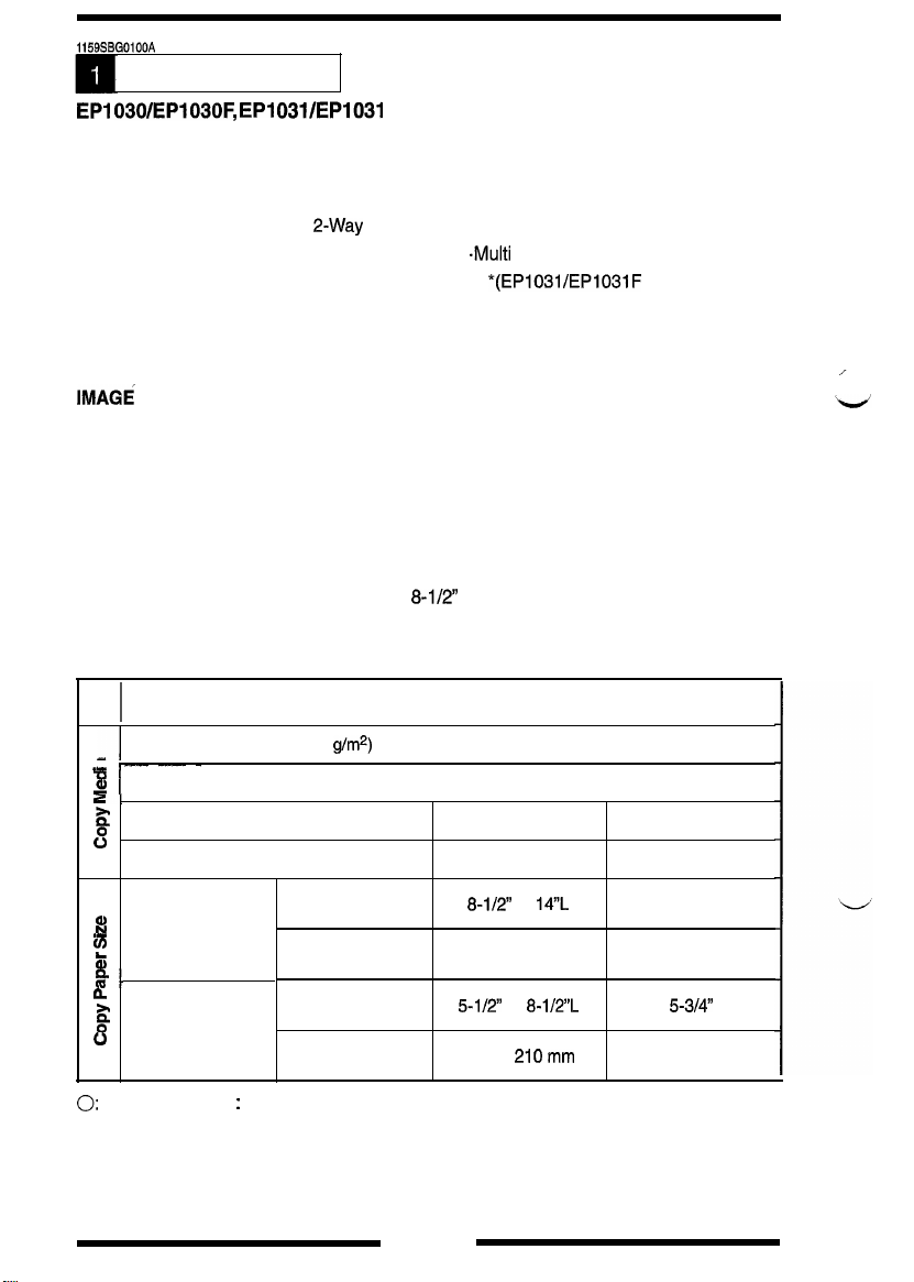
SPECIFICATIONS
EPI 030/EP103OF, EPI
TYPE
PHOTOCONDUCTOR
COPYING SYSTEM
PAPER FEEDING
SYSTEM
EXPOSURE SYSTEM
DEVELOPING SYSTEM
CHARGING SYSTEM
IMAGE TRANSFER
SYSTEM
PAPER SEPARATING
SYSTEM
FUSING SYSTEM
PAPER CHARGE
NEUTRALIZATION
ORIGINAL SIZE
COPY PAPER
031/EP1031 F Specifications
Desk Top Copier with Stationary Platen
Organic Photoconductor
Electrostatic Dry Powdered Image Transfer to Plain Paper
2-Way
Feeding
Slit exposure
New Micro-Toning System
Comb Electrode DC Negative Charger with Scorotron Grid
Visible Image Transfer by means of a Single-Wire DC
Negative Charger
Natural separation from the small-diameter PC Drum
because of the inherent strength in paper, plus DC bias
Roller packed with heat insulator
Charge Neutralizing Brush
Inch Areas:
Metric Areas: 210 x 297 mm (A4)
Universal Tray (250 sheets)
-Multi
Bypass Table (30 sheets)*
*(EPl03l/EPl03lF
8-l/2
x 14 (Legal)
only)
_I
.I
D
s!
2
s
8
._
to
5
4.
a
g
”
(width x length)
0:
Acceptable
Plain paper (60 to 90
_-_- ---- -
I
Thick paper (up to 110 g/m*)
(width x length)
OHP transparencies
Postcards
Max.
Min.
x : Unacceptable
Universal Tray
(automatic take-up)
g/m2)
Inch Areas
Metric Areas 210 x 297 mm
Inch Areas
Metric Areas
I
I
0
X
X
X 0
8-l/2”
x
14”L
5-l/2”
x
8-ll2”L
148 x
210mm
G-l
Multi Bypass Tray
(30 sheets)
I
I
0
0
0
8-W’ x 14”L
210 x 297 mm
4’ x
53/4”
mm
98 x 140 mm
Page 7
MULTIPLE COPIES
WARMING-UP TIME
:
Up to 99 copies (in SDH mode)
I
I
I
I
I
I
FIRST COPY SPEED
CONTINUOUS COPY SPEED (copies/min.)
Zoom ratio x 1.00, paper fed from Universal Tray
I
1-1
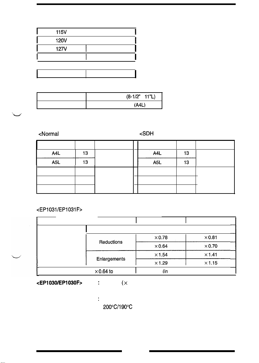
ZOOM RATIOS
<EPl031/EPlO311=>
115v
12ov
127V
220v
230V
240V
inch Areas
Metric Areas 6.5 sec. or less
<Normal
Mode>
Size
Legal L
Letter L
Invoice L
13
13
13
9.9 sec.
I
9.1 sec.
I
7.5 sec.
I
10.9 sec.
I
9.9 sec.
I
9.1 sec.
6.4 sec. or less (8-l/2 x
Area
Metric
Inch
I
I
I
I
I
I
11L)
(A4L)
cSDH
I
1-1
Mode>
Size
Legal L
Letter L
Invoice L
12
13
13
Area
Metric
Inch
I
Fixed Ratios
1
Variable Ratios I
cEP1030/EP1030Fr
LENS
EXPOSURE LAMP
FUSING
TEMPERATURE
Inch Areas1 Metric Areas
I
Full Size
x0.64to
xl.56
Full size (x 1 .OO) only
:
Through Lens (F = 7.5, f = 165 mm)
:
Halogen Frost Tube Lamp
200%/190c
I
I
G-2
x 1 .oo
(in
x 0.01 increments)
Page 8
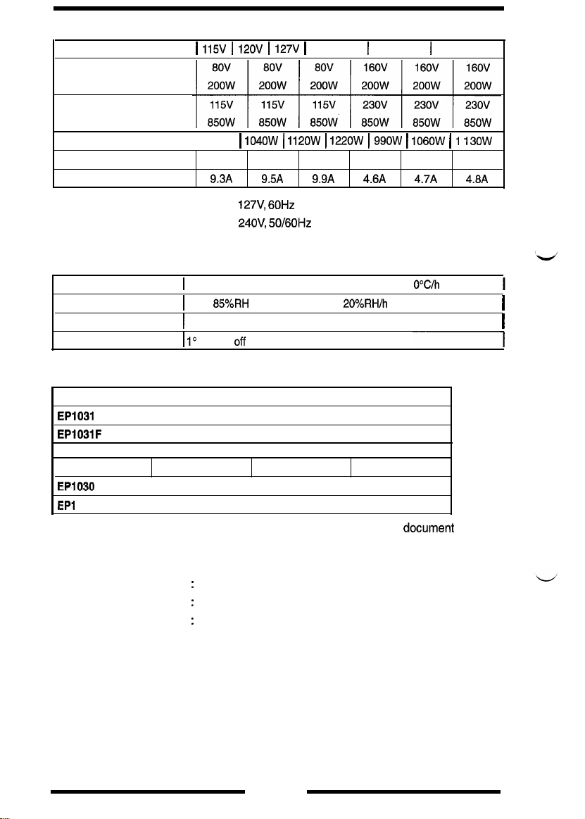
POWER/CURRENT CONSUMPTION (Copier only)
1
115V 1 12OV 1
Exposure Lamp
(Rating)
Fusing Heater
(Rating)
Max. power consumption 1 1040~ ( 1120~ 1 1220~
In standby
Max. current consumption
290w
9.3A 9.5A 9.9A
320W
127V 1
220V 1 230V 1 240V
360W 280W 3oow
1 99ow I
4.6A
106OW
( 1
4.7A 4.8A
I
30~
330w
POWER
REQUIREMENTS
ENVIRONMENTAL REQUIREMENTS
Temperature
Humidity
Ambient llluminance) 300 lux or less
Inclination
Copier Dimensions (mm)
EP1031
EP1031F
EP1030
EPI
030F
*Including SDH (For a copier not equipped with an SDH, up to the
level)
COPIER WEIGHT (excluding Copy Tray, starter, toner, and copy paper)
WITH SDH
WITHOUT SDH
ACCESSORIES
: 115 to
I
10
I
15 to
I 1
Width
I
558
I
558
I
Width Depth
523
I
529
I
:
25 kg
:
22 kg
:
127V,
60Hz
220 to
24OV,
50/60Hz
to 35C (50 to 95F) (Temperature Gradient 1
85%RH
(Humidity Gradient
or less
off
horizontal
Depth
I
451
I
456
I
451
I
456
I
Operators Manual, Setting-up Instructions, Exit Tray
20%RH/h
I
I
I
I
I
or less)
---I
Height*
281
357
Height*
281
358
documenZ
OC/h
or less)
I
I
surface
G-3
Page 9
SDH Specifications
NAME
TYPE
INSTALLATION
TYPE OF DOCUMENT
DETECTABLE
DOCUMENT SIZE
TRAY CAPACITY :
ALIGNMENT
DOCUMENT PLACEMENT:
MODE
POWER REQUIREMENTS :
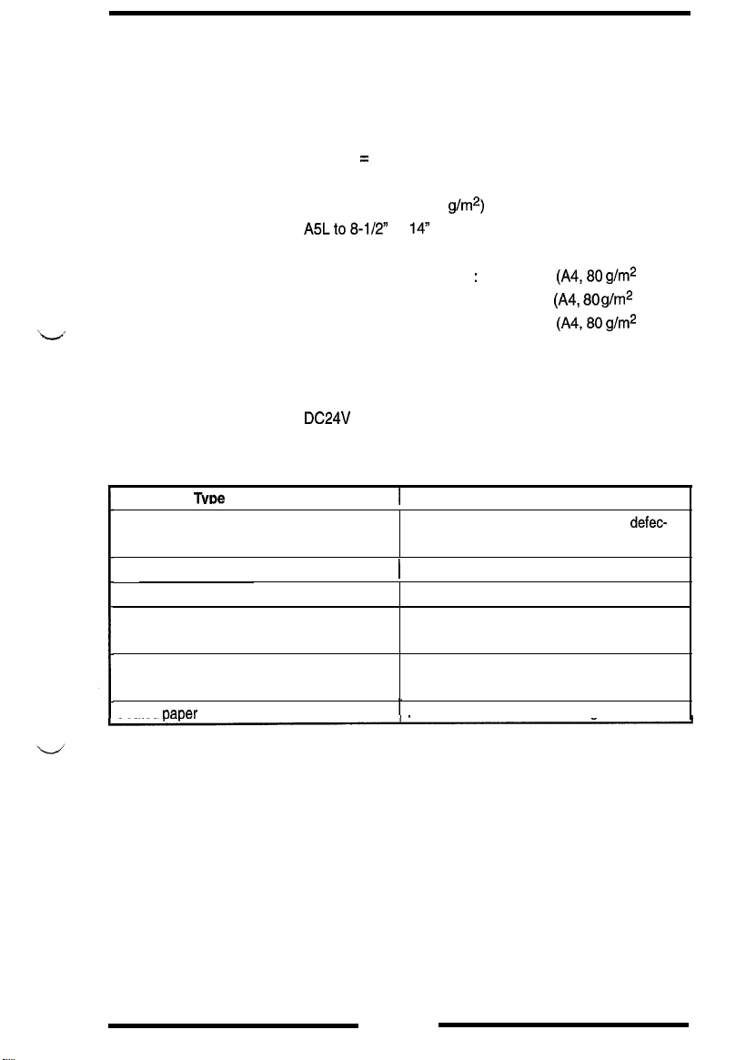
DOCUMENTS WHICH :
CANNOT BE USED
Semi-Automatic Document Handler (SDH)
Take-Up = Straight take-up from the top of the stack of
documents
Transport = Roller transport
Ejection = Roller transport and U-turn ejection
Mounted on top of copier
Plain paper (50 to 110
:
A5Lto8-112
Document Feeding Tray
Document Exit Tray
Centrally aligned
Face down
DC24V
The following types of documents, if used in the SDH, are very
likely to cause trouble.
x
(supplied from copier)
14
g/m2)
:
50 sheets
30 sheets
:
50 sheets
(A4,80 g/m2
(A4,80 g/m2
(A4,80 g/m2
or less)
or more)
or less)
TvDe
of Document
Documents stapled or clipped together
Plastic transparencies
Documents glued together
Documents folded, torn, or wrinkled
Documents severely curled
Coated oaber Documents misfed due to being fed askew
I
Take-up failure, damaged document,
tive drive train due to jammed staples or clips.
1
Take-up failure due to static electricity
Take-up failure, damaged document
Damaged document, documents misfed due
to being fed askew
Documents misfed due to being dog-eared or
fed askew
Possible Trouble
defec-
G-4
Page 10
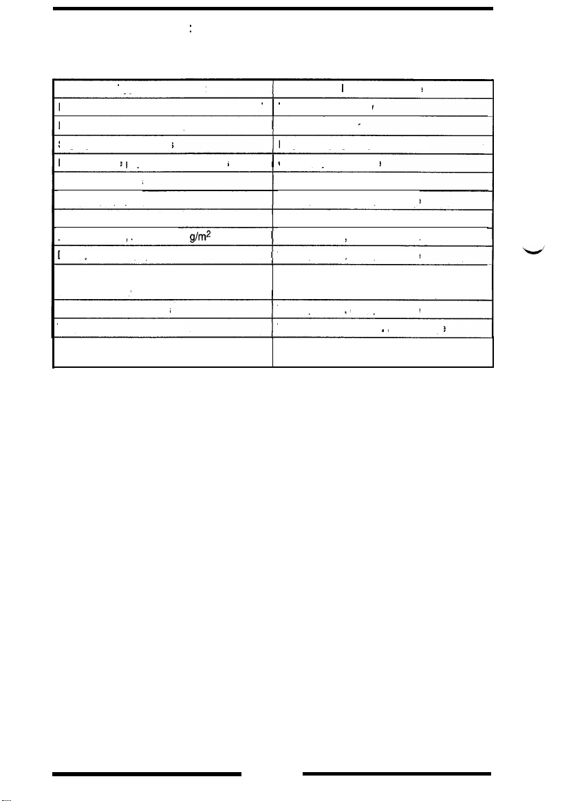
DOCUMENTS FOR
WHICH FEEDING
CANNOT BE GUARANTEED
:
The following types of documents, if used in the SDH, may or
may not cause trouble.
Type of Document
Paper to which Scotch tape has been applied
Documents pasted with cut
Slightly curled documents
Heat-sensitive
Coated documents
Translucent paper
Paper just fed out of copier
Paper weighing less than 50
Damp,
Paper with an extremely rough surface
(letterhead, etc.)
Pencil-written documents Take-up failure,
Two-fold, Z-fold documents
Documents of a nonstandard size with a
width of 139.7 mm to 216 mm
paper for fax machines
untensile paper
paper
g/m2
Take-up failure, skew
Torn pasted paper
Dog-eared pages, ejection failure
I
Crease, ejection failure
Take-up failure
Take-up failure,
Take-up failure, transport failure
Take-up failure,
Take-up failure, transport failure
Take-up failure, transport failure
Transport failure, folded leading edge
Transport failure, distorted image.
Possible Trouble
transport failure
transport failure
transport failure
G-5
Page 11
1159Sl3GO200A
PRECAUTIONS FOR INSTALLATION
n
Installation Site
To ensure safety and utmost performance of the copier, the copier should NOT be
used in a place:
0
Where it will be subject to extremely high or low temperature or humidity.
0
Which is exposed to direct sunlight.
0
Which is in the direct air stream of an air conditioner, heater or ventilator.
0
Which puts the operator in the direct stream of exhaust from the copier.
a
Which has poor ventilation.
0
Where ammonia gas might be generated.
l
Which does not have a stable, level floor.
0
Where it will be subject to sudden fluctuations in either temperature or humidity,
If a cold room is quickly heated, condensation forms inside the copier, resulting in
blank spots in the copy.
l
Which is near any kind of heating device.
0
Where it may be splashed with water.
0
Which is dirty or where it will receive undue vibration.
0
Which is near volatile flammables or curtains.
W
Power Source
Use an outlet with a capacity of
or more.
0
If any other electrical equipment is
that the capacity of the outlet is not exceeded.
0
Use a power source with little voltage fluctuation.
0
Never connect by means of a multiple socket any other appliances or machines
to the outlet being used for the copier.
0
Make the following checks at frequent intervals:
l
Is the power plug abnormally hot?
l
Are there any cracks or scrapes in the cord?
l
Has the power plug been inserted fully into the outlet?
o
Does something, including the copier itself, ride on the power cord?
0
Ensure that the copier does not ride on the power cord or communications cable
of other electrical equipment, and that it does not become wedged into or under-
neath the mechanism.
115/l
20/l
27V, 13.2A
sourced
or more, or
200/220/24OV, 8.1A
from the same power outlet, make sure
W
Grounding
To prevent receiving electrical shocks in the case of electrical leakage, always ground
the copier.
l
Connect the grounding wire to:
l
The ground terminal of the outlet.
l
A grounding contact which complies with the local electrical standards.
0
Never
connect the grounding wire to a gas pipe, the grounding wire for a telephone,
or a water pipe.
G-6
Page 12
PRECAUTIONS FOR USE
To ensure that the copier is used in an optimum condition, observe the following precautions.
0
Never place a heavy object on the copier or subject the copier to shocks,
0
Insert the power plug all the way into the outlet.
0
Do not attempt to remove any panel or cover which is secured while the copier is
making copies.
0
Do not turn OFF the Power Switch while the copier is making copies.
0
Provide good ventilation when making a large number of copies continuously,
0
Never use flammable sprays near the copier.
@
If the copier becomes inordinately hot or produces abnormal noise, turn it OFF and
unplug it.
l
Do not turn ON the Power Switch at the same time when you plug the power cord
into the outlet.
0
When unplugging the power cord, do not pull on the cord; hold the plug and pull
it out.
l
Do not bring any magnetized object near the copier.
0
Do not place a vase or vessel containing water on the copier.
0
Be sure to turn OFF the Power Switch at the end of the workday or upon power
failure.
0
Use care not to drop paper clips, staples, or other small pieces of metal into the
copier.
n
Operating Environment
The operating environmental requirements of the copier are as follows.
e
Temperature:
l
Humidity: 15% to 85% RH with a fluctuation of 10% RH per hour
10C
to 30C with a fluctuation of 10C per hour
n
Power Requirements
The power source voltage requirements are as follows.
AC1
15/l
20/l
l
Voltage Fluctuation:
l
Frequency Fluctuation:
f
10% (Copying performance assured)
-15% (Paper feeding performance assured)
(AC1 27V
50/60
27l22Ol23Ol24OV
: Tyo %)
Hz
&0.3%
G-7
Page 13

1159SBG0400A
HANDLING OF THE CONSUMABLES
Before using any consumables, always read the label on its container carefully.
0
Use the right toner. The applicable copier model name is indicated on the Toner
Bottle.
l Paper is apt to be easily damaged by dampness, To prevent absorption of
moisture, store paper, which has been removed from its wrapper but not loaded
into the drawer, in a sealed plastic bag in a cool, dark place.
0
Keep consumables out of the reach of children.
0
Do not touch the PC Drum with bare hands.
l
Store the paper, toner, and other consumables in a place free from direct sunlight
and away from any heating apparatus.
l
The same sized paper is of two kinds, short grain and long grain, Short grain paper
should only be fed through the copier crosswise, long grain paper should only be
fed lengthwise.
0
If your hands become soiled with toner, wash them with soap and water
immediately.
0
Do not throw away any used consumables (PC Drum, starter, toner, etc.). They are
to be collected.
NOTE
Do not burn, bury in the ground, or throw into the water any
consumables (PC Drum, starter, toner, etc.).
G-8
Page 14
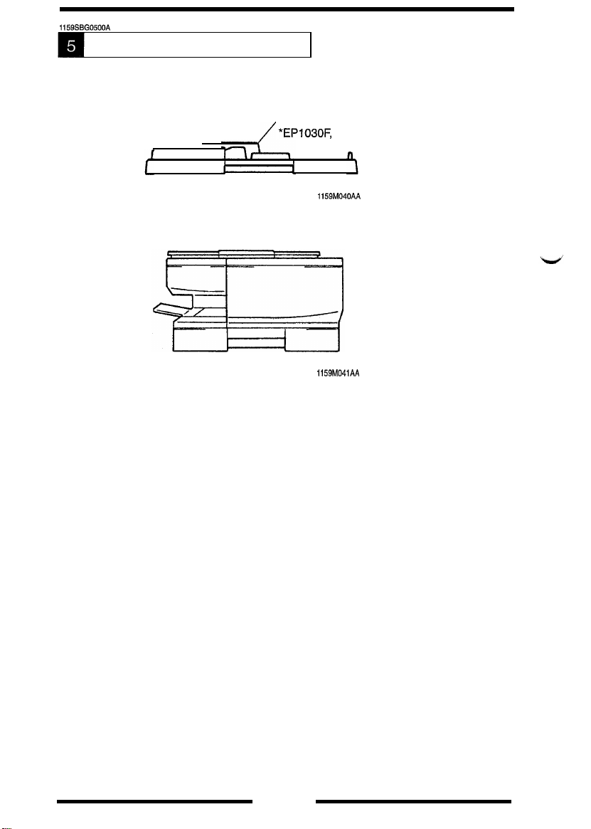
1159SBG0500A
SYSTEM CONFIGURATION
1
Semi-Automatic Document
Handler (SDH)*
/ *EP1030F,
EP1031 F Only
1159M040AA
1159M041AA
G-9
Page 15

1151 SBMOOOCA
MECHANICAL/
ELECTRICAL
Page 16
1159SBMOl
OOA
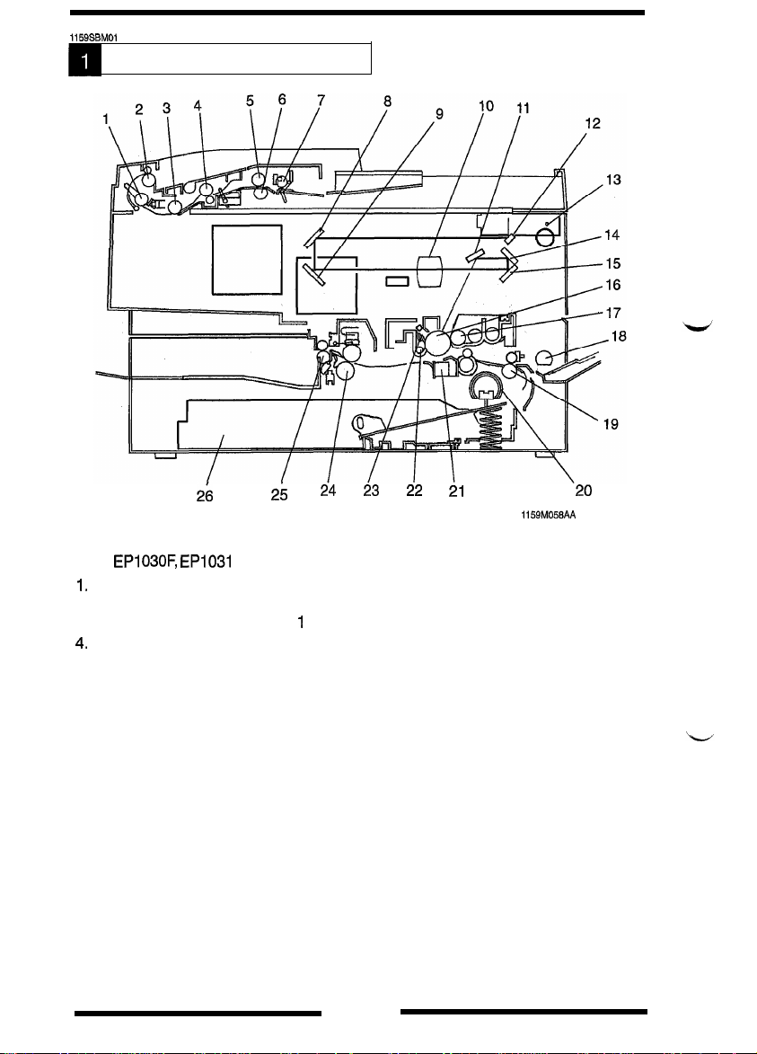
CROSS-SECTIONAL VIEW
2ii
SDH: EPI
1.
2.
3.
4.
03OF, EP1031
Document Transport
Document Exit Roller
Document Transport Roller
Document Registration Roller
Copier
2nd Mirror
a.
3rd Mirror
9.
IO. Lens
6th Mirror
11.
1st Mirror
12.
13.
Exposure Lamp
5th Mirror
14.
4th Mirror
15.
PC Drum
16.
Magnet Roller
17.
F only
Roller
24 23 22 21
25
2
1
1159M058AA
Document Feed Roll
5.
Document Separator Roll
6.
Document Take-Up Roll
7.
18.
Multi Bypass Take-Up Roll
Transport Roller
19.
20.
Paper Take-Up Roll
21.
Image Transfer/Paper Separator
Coronas
22.
Main Erase Lamp
Cleaning Blade
23.
Fusing Roller
24.
Exit Roller
25.
Universal Tray
26.
20
M-l
Page 17
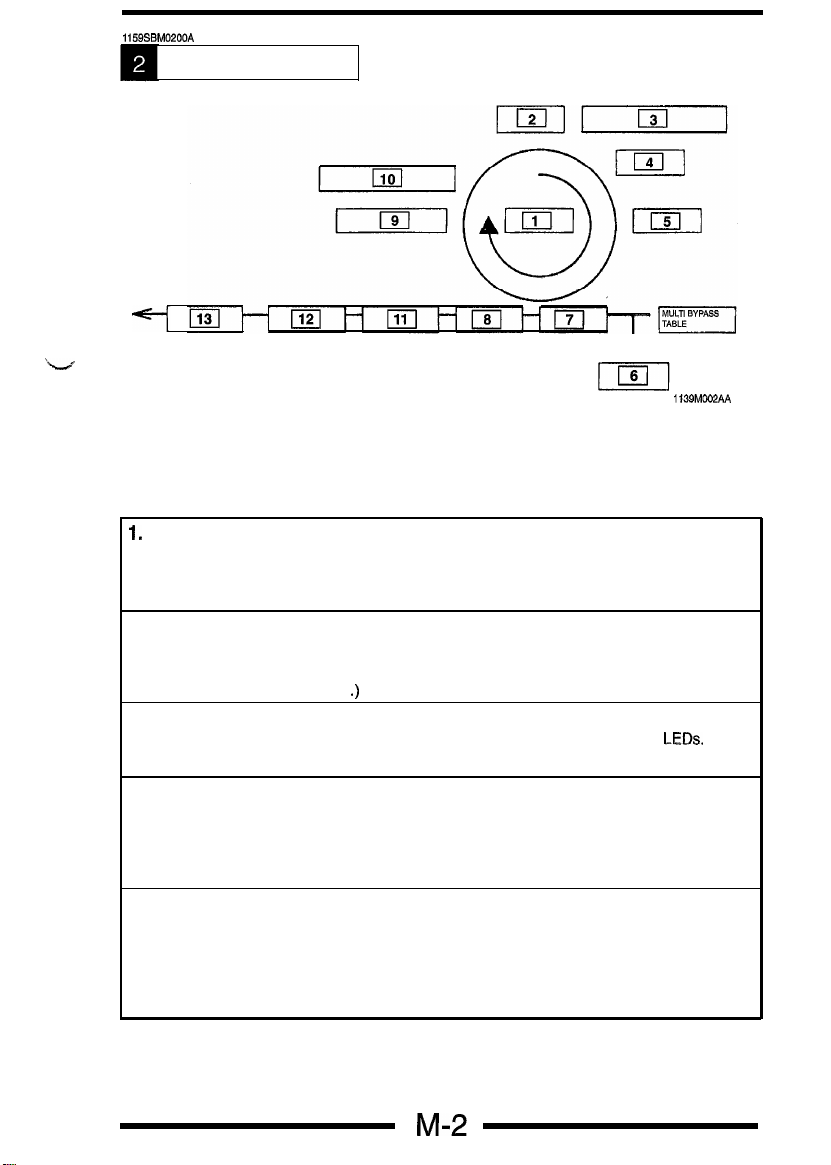
1159SBM0200A
COPY PROCESS
k-.f
1.
PC DRUM
2.
DRUM CHARGING
3.
IMAGE ERASE
4.
EXPOSURE
5.
DEVELOPING
6.
PAPER FEEDING
7.
IMAGE TRANSFER
1.
PC Drum
8.
PAPER SEPARATION
9.
CLEANING
10.
MAIN ERASE
11.
TRANSPORT
12.
FUSING
13.
PAPER EXIT
I
1139MOO2AA
The PC Drum is an aluminum cylinder coated with a photosensitive semiconductor.
It is used as the medium on which a visible developed image of the origlnal is formed.
(For more details, see p. M-9.)
2. Drum Charging
The PC Drum Charge Corona Unit is equipped with a Comb Electrode and a Scorotron Grid to
deposit a uniform negative charge across the entire surface of the PC Drum.
(For more details, see p. M-21
.)
3. Image Erase
Any areas of charge which are not to be developed are neutralized by lighting up
(For more details, see p. M-22.)
LEDs.
4. Exposure
Light from the Exposure Lamp reflected off the original is guided to the surface of the PC
Drum and reduces the level of the negative charges, thereby forming an electrostatic latent
image.
(For more details, see p. M-24.)
5.
Developing
Toner positively charged in the Developer Mixing Chamber is attracted onto the electrostatic
latent image changing it to a visible, developed image. A DC negative bias voltage is applied
to the Sleeve/Magnet Roller to prevent toner from being attracted onto those areas of the PC
Drum which correspond to the background areas of the original.
(For more details, see p. M-12.)
Page 18
6. Paper Feeding
Paper is fed either automatically from the Drawer, or manually via the Multi Bypass Table or
Manual Bypass Table. Each Drawer has fingers that function to separate the top sheet of
paper from the rest at take-up.
(For more details, see p. M-34.)
7. Image Transfer
The single-wire Image Transfer Corona Unit applies a DC negative corona emission to the
underside of the paper, thereby attracting toner onto the surface of the paper.
(For more details, see p. M-33.)
8. Paper Separation
The paper, thanks to its inherent strength, is naturally separated from the small-diameter PC
Drum. This is combined with the application of a positive DC bias with a comb electrode. The
two methods ensure that the paper is definitely separated from the surface of the PC Drum.
(For more details, see p. M-33.)
9. Cleaning
Residual toner on the surface of the PC Drum is scraped off by the Cleaning Blade.
(For more details, see p. M-l 8.)
10. Main Erase Lamp
The Main Erase Lamp applies a positive DC charge to neutralize any surface potential remaining on the surface of the PC Drum after cleaning.
(For more details, see p. M-32.)
11. Transport
The paper is fed to the Fusing Unit by the Guide Plate.
(For more details, see p M-45.)
12. Fusing
The developed image is permanently fused to the paper by a combination of heat and
pressure applied by the Upper and Lower Fusing Rollers.
(For more details, see p. M-46.)
13.
Paper Exit
After the fusing process, the paper is fed out by the Paper Exit Roller onto the Copy Tray.
(For more details, see p. M-49.)
Page 19
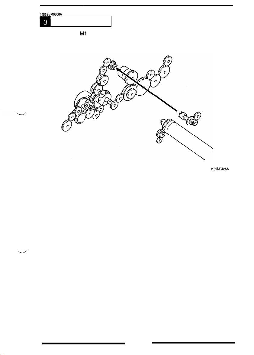
1159SBM0300A
DRIVE SYSTEM
Main Drive Motor Ml of this copier is used to drive the Imaging Unit, paper take-up and
transport mechanisms, and Fusing Unit. Its drive is transmitted via gear trains as follows.
1159M042AA
M-4
Page 20
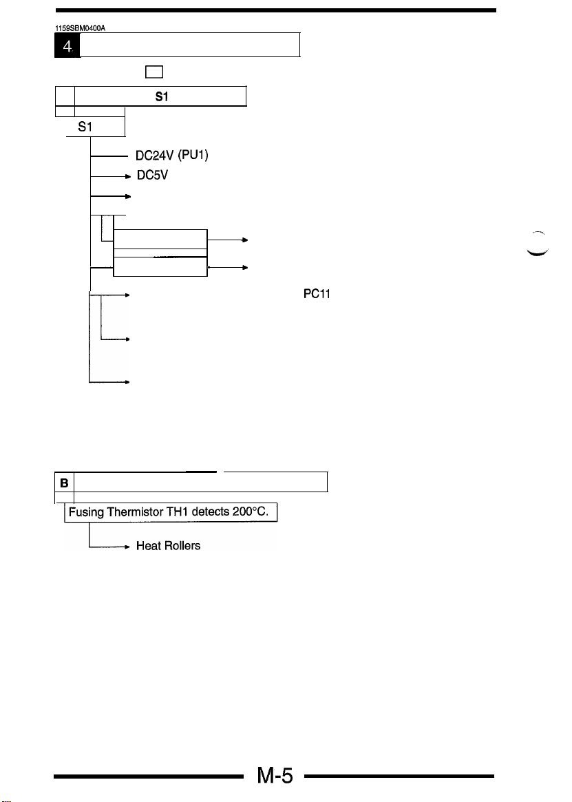
1159SBM0400A
OPERATIONAL SEQUENCE
*Figures given in 0 in the following flowchart represent timer values in seconds,
A
Power Switch Sl is turned ON.
Sl
ON
.
DC24V
(PUl)
t DC5V
c
Control panel
. Ozone Fan Motor M3 turns at full speed.
Approx. 500ms
-
Approx. Is
Scanner Home Position Sensor
*Scanner Drive Motor M4 is energized to move it to the
home position.
Lens Home Position Sensor PC1 2
*Lens Drive Motor M5 is energized to move it to the home
E
B
Fusing Unit temperature is detected at 200%.
position.
Starter set sequence and ATDC automatic adjustment
(After the warming-up cycle is completed)
*Only when the Imaging Unit is new.
Fuse is blown when the starter setup sequence is normally
terminated.
*Fusing temperature control starts.
+
Ozone Fan Motor M3 turns at half speed.
-
+
Heat Roller
PC11
M-5
Page 21
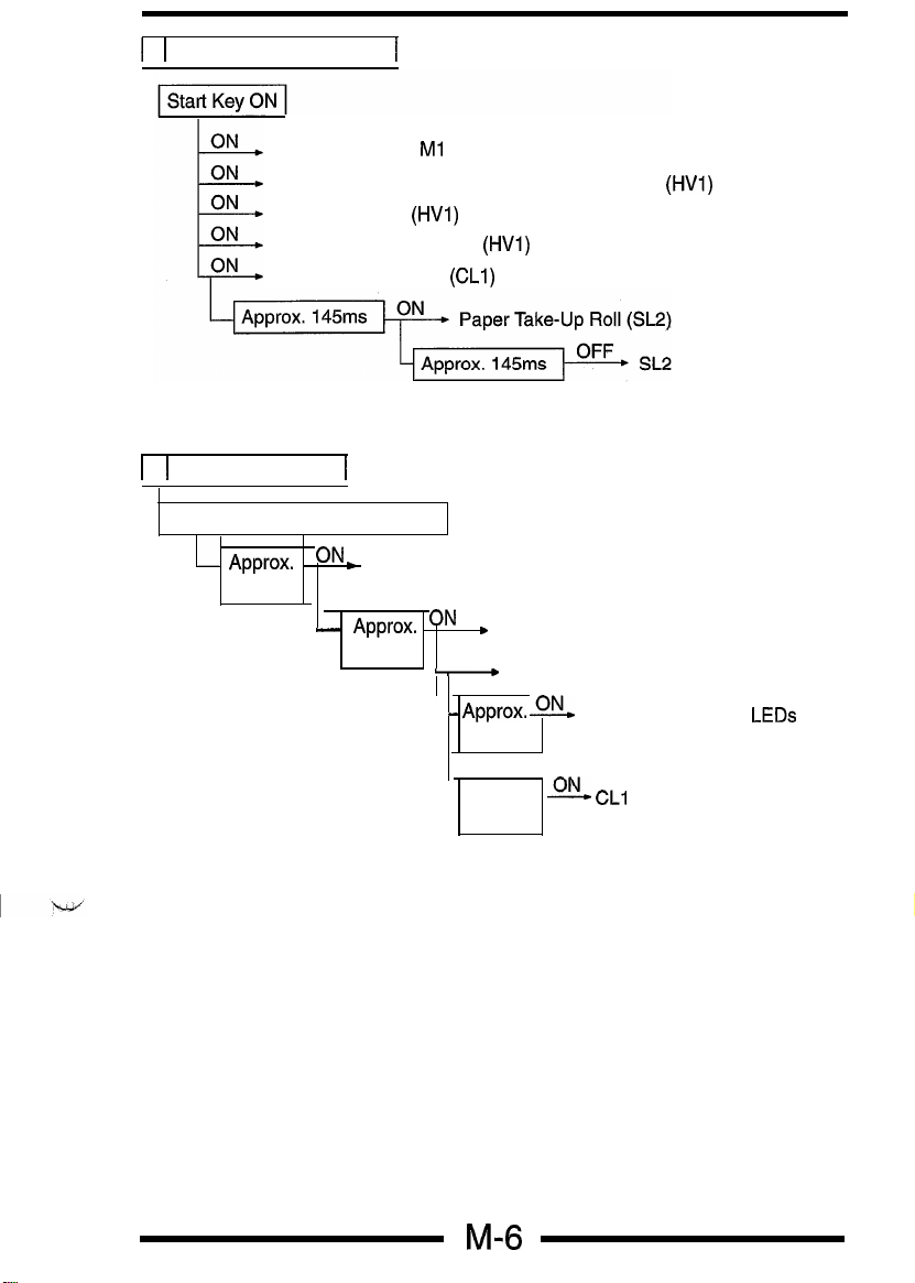
1
C 1 The Start Kev is pressed.
1
Main Drive Motor
PC Drum Charge and Image Transfer Coronas (HVI)
Developing bias
Paper Separator Corona (HVI)
Synchronizing Roller
1
D 1 Paper is taken up.
Paper Take-Up Solenoid SL2 ON
APProx.ON c Paper Transport Sensor PC2
1.1s
I
- APProx. ONb Scanner Drive Motor M4
473ms
OFF
Ml
(HVI)
(CLI)
-
- APProx. z
Scanner Home Position Sensor PC11
134ms
Image Eraser LA3
LEDs
Approx.
266ms
M-6
-@!. CL1
Page 22
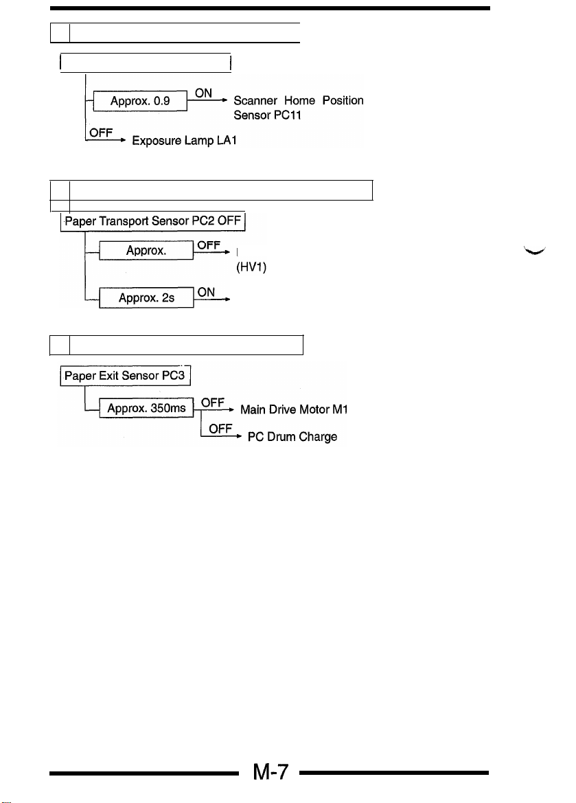
E
The Scanner completes the scan motion.
1
Scanner starts the return motor
F
The last paper moves past Paper Transport Sensor PC2.
G
Paper moves past Paper Exit Sensor PC3.
1
PC Drum Charge and Image Transfer Coronas
Paper Exit Sensor PC3
M-7
Page 23
1151
J7ciwi-j
SBM0500A
k.4+
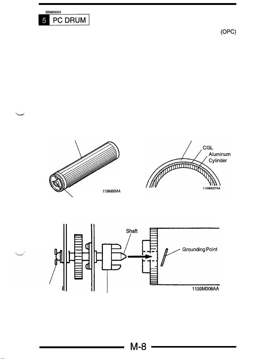
The photoconductive drum used in this copier is the organic photoconductor
(OK)
type. The drum is made up of two distinct, semiconductive materials on an alumi-
num alloy base. The outer of the two layers is called the Charge Transport Layer
(CTL), while the inner layer is called the Charge Generating Layer (CGL).
The PC Drum has its grounding point inside at its rear end. When the Imaging Unit
is installed in the copier, the shaft on which the PC Drum Drive Coupling Gear is
mounted contacts this grounding point.
Handling Precautions
This photoconductor exhibits greatest light fatigue after being exposed to light over
an extended period of time. It must therefore be protected from light by a clean, soft
cloth whenever the Imaging Unit has been removed from the copier. Further, use
utmost care when handling the PC Drum to prevent it from being contaminated.
PC Drum Cross-Sectional
PC Drum
113QM006AA
Gear
View
CTL
Grounding
Plate
. -
I
1139M008AA
PC Drum Drive Coupling Gear
M-8
Page 24

1159SBM0600A
IMAGING UNIT
This copier is equipped with an Imaging Unit, or
NJ,
which integrates a PC Drum,
PC Drum Charge Corona, Developing Unit, Cleaning Unit, and Toner Recycling
mechanism into one assembly. The Unit also includes the Upper Synchronizing
Roller which facilitates clearing of a paper misfeed.
I
PC Drum Charge
Corona
1159M043AA
1159M044AA
Coupled to
in Copier
GeaS
/
PC Drum
Upper Synchronizing Roller
1159M045AA
Page 25

1159SBM0601A
6-1. Imaging Unit Drive
Drive for the Imaging Unit is transmitted by one of the gears on the Unit.
This particular gear is in mesh with the Imaging Unit Drive Gear
Developer Mixing Screw Drive Gear
/
in
the
copier.
I
Coupling (in Copier)
Toner Recycling Coil Drive Gears
M-10
Page 26

1159SSM0602A
6-2. Toner Recycling
The copier is provided with a toner recycling mechanism. The toner, which has been
scraped off the surface of the PC Drum by the Cleaning Blade and collected in the
Cleaning Unit, is conveyed by the two Toner Recycling Coils to the Toner Supply
Port and, from there, it is returned back to the Developer Mixing Chamber of the
Developing Unit.
One of the gears of the Toner Recycling mechanism (1) receives drive through a
gear at the rear end of the PC Drum.
The gear on Toner Recycling Coil 1 receives drive through a gear at the rear end
of the PC Drum. While, the gear on Toner Recycling Coil 2 receives drive through
a train of three gears mounted on the mechanism from the Developing Unit to Hopper.
Toner
Recycling Coil 2
-c\
1169SBM0603A
6-3. IU Fuse
Toner Recycling Coil
Fl
1
The Imaging Unit is provided with a fuse called IU Fuse Fl. When a new Imaging
Unit is installed in the copier and the Power Switch turned ON, an IU Set signal is
output causing the copier to start the starter setup sequence and ATDC Sensor
automatic adjustment.
When the starter setup sequence is completed normally, an IU Fuse Blow signal
is output to blow
Fi.
Once Fl is blown, the IU Set signals are no longer output. This
means that the starter setup sequence and ATDC Sensor automatic adjustment will
not be carried out when the Power Switch is thereafter turned ON.
When Fuse is When Fuse is
not Blown Blown
H
L
WIRING DIAGRAM
2-B
Fi
Control Signal
PWB-A PJl OA-5
M-11
Page 27

1159SBM0700A
DEVELOPMENT
The Developing Unit built into the Imaging Unit performs the following functions:
l
Mixes the toner and carrier well to ensure that a sufficient amount of toner is
positively charged.
l
Detects the toner-to-carrier ratio of the developer by means of the ATDC Sensor
and replenishes the supply of toner as necessary.
l
Detects a toner empty condition by means of the ATDC Sensor.
l
Ensures that a proper amount of toner is attracted to the PC Drum by means of
its Sleeve/Magnet Roller, Developing Bias, and Doctor Blade.
2nd Developer
Doctor Blade
Sleeveklagnet Roller
lst Developer
Mixing Screw
Mixing Screw
\
ATDC Sensor
1159M003AA
M-12
Page 28

1159SBM0701 A
7-1 I ATDC Sensor
ATDC Sensor UN3 installed on the underside of the Developer Mixing Chamber
detects the varying toner-to-carrier ratio of the developer which flows over it in the
Chamber. The copier CPU compares the detected ratio with the ratio set by the
ATDC Detection Level Mode (Tech. Rep. Choice SCH-90) to control toner
replenishment.
1
Set
T/C (%)
1
ATDC Output Voltage (V)
1
2.65
1
6.0
6.5
7.0 2.15
The Toner Bottle is turned one turn (30 mg) to replenish the supply of tonerforeach Toner
Replenishing signal.
If the toner-to-carrier ratio becomes lower than 2.5%, the copier inhibits the initiation
of a new copy cycle (this feature can be enabled or disabled by a Tech. Rep. Choice
function). When a ratio of 2.5% or more is recovered as a result of Auxiliary Toner
Replenishing, the copier permits the initiation of a new copy cycle.
If the Front Door is swung open and closed with a T/C ratio of less than
er initiates an Auxiliary Toner Replenishing sequence. (It stops the sequence as
soon as a T/C ratio of 5% is reached.)
1
2.32
2.32
I
4%,
the copi-
ATDC Sensor Automatic Adjustment
An automatic adjustment of the ATDC Sensor is made in the F8 Test Mode
operation and when a new Imaging Unit is installed in the copier.
*When a New Imaging Unit is Installed in the Copier:
Following the execution of the starter setup mode upon power-up, the copier
CPU reads the output value of the ATDC Sensor and establishes the reading
as the reference value.
*When F8 is Run after Starter Has Been Changed:
Following the execution of the starter setup mode upon pressing of the Start
Key, the copier CPU reads the output value of the ATDC Sensor and establishes
the reading as the reference value.
. .
NOTE:
lfan F8 operation is run at a time when the starter has not been changed,
it can result in a wrong T/C reference value being set by the copier. Avoid
casual use of
If the setting value has been cleared because the RAM Board was
replaced, set the value valid before the replacement for the ATDC Sensor
adjustment data of the Adjust mode using the 1
F8.
Oup/lup
key,
M-13
Page 29

Toner Empty Detection
The copier has no toner empty detecting sensor and, instead, the ATDC Sensor
performs that function. The toner-empty condition is canceled after detection under
any of the following conditions:
l
The set T/C ratio has been recovered.
l
After the Front Door has been swung open and closed.
(For details, see
9-2.
Toner Replenishing Control on
p.M-20.)
UN3
Control Signal
PWB-A
PJl
OA-2
Set T/C
4.0%
4.5%
5.0%
5.5% 2.40 2-A
6.0% 2.32
6.5%
7.0%
Standard
output
Voltage
2.65
2.57
2.48
2.32
2.15
WIRING DIAGRAM
M-14
Page 30

1159SBM0702A
7-2. Magnet Roller
The Magnet Roller of the Sleeve/Magnet Roller of this copier has the following
magnetic characteristics.
The Sleeve Roller, onto which developer is attracted by the magnetic fields of force
set up by the poles of the Magnet Roller, turns to convey the developer toward the
point of development. It also means that
developer fresh
from the Developer Mixing
Chamber is always brought to the point of development.
As we noted earlier, the Imaging Unit integrates the Developing Unit with the PC
Drum into one body. Because of that, it is impossible to move the Developing Unit
against the PC Drum, thereby providing a certain distance between the PC Drum
and Sleeve/Magnet Roller. The Magnet Roller has therefore been made movable:
the Bushing is pressed by compression springs thereby pressing the Positioning
Collars on both ends of the Magnet Roller against the PC Drum. This ensures a
given distance between the PC Drum and the Sleeve/Magnet Roller.
Magnetic Pole Positioning
N3
PC Drum
N2
1159M004AA
Spring
1139M017AA
M-15
Page 31

1159SSM0703A
7-3. Developing Bias
A negative voltage (Vb = Developing Bias voltage) is applied to the Sleeve Roller
to prevent a foggy background on the copy. The amount of toner attracted onto the
surface of the PC Drum depends on how much lower the PC Drum surface potential
(Vi) is than Vb (i.e., the potential difference).
l When the potential difference is large, a greater amount of toner is attracted.
l When the potential difference is small, a smaller amount of toner is attracted.
Magnet Roller
/
I
1159M005AA
Start Key
PC Drive Motor Ml
:;,n
CFF
ON 2
Developing Bias PWB-A
I
I I
Control Signal ON OFF WIRING DIAGRAM
PJ8A-4
L
I
Approx. 0.5
H
set
115iTOiMCA
12-F
M-16
Page 32

1159SBM0704A
7-4. Doctor Blade
The Doctor Blade installed over the Sleeve/Magnet Roller regulates the height of
the developer brush on the surface of the Sleeve Roller. The Blade is perpendicular
to the direction of movement of the Magnet Roller to minimize variations in the distance between the Doctor Blade and Magnet Roller as the Magnet Roller moves.
Doctor Blade
r-6
Direction of Magnet
Roller Movement
1159SBM0705A
7-5. Magnet Roller Lower Filter
There is a seal installed under the Magnet Roller to prevent insufficiently charged
from spilling onto the mechanisms inside the copier and toner particles from flying out.
u
Magnet Roller
1159M006AA
toner
M-17
1159M007AA
Page 33

CLEANING UNIT
The Cleaning Blade is pressed tightly against the surface of the PC Drum and
scrapes off any toner remaining on the surface after image transfer and paper sepa-
ration have been completed.
The Cleaning Blade is moved back and forth to prevent the PC Drum from deterio-
rating and the Cleaning Blade from warping away from the surface of the PC Drum.
There is a Toner Antispill Mylar aff ixed to the Imaging Unit. It prevents toner scraped
off the surface of the PC Drum from falling down onto the surface of the copy paper
or the paper path.
In addition, a Side Seal is affixed to both ends of the Imaging Unit on both sides of
the Cleaning Blade. They prevent toner from spilling from both ends of the Cleaning
Blade.
Cleaning Blade
Tension
(
/
/
bP
Ton& Antispill Mylar
/
.
\
3
\
1139MOZAA
M-18
115QMOdQAA
Blade Lateral
Movement Cam
Page 34

1159SBM0900A
TONER HOPPER
The Toner Hopper is integrated into the Imaging Unit. To replace an empty Toner
Bottle, the user first needs to swing the Toner Bottle Holder out 20 to the front. The
Holder pivots about the Toner Supply Port as it is swung out or in, which effectively
prevents toner from spilling when the Holder is swung out or in.
Toner Bottle
Toner Bottle Holder
20
Lock
1159M039AA
1159SBM0901A
9-I.
Toner Replenishing
Drive from Main Drive Motor Ml is transmitted via the Magnet Roller to the Bottle Drive
Gear in the gear box. There is a holder installed on the Bottle Drive Gear, coupling the
Toner Bottle to the Bottle Drive Gear. This ensures that the Bottle Drive Gear turns with
the Toner Bottle. When Toner Replenishing Solenoid
gized, it turns the Toner Bottle one complete turn. The spiral groove cut in the Toner
Bottle effectively prevents toner from remaining in the bottle.
SLl,
fitted to the gear box, is ener-
Toner Replenishing
Solenoid
(SLl)
M-19
1159M057AA
Page 35

1159SBM0902A
9-2. Toner Replenishing Control
When Power is Turned ON
l
If the toner-to-carrier ratio (T/C) data stored in memory when power was last turned
1
OFF is less than -1% of the set level, the copier is set into the auxiliary toner replenishing sequence after it has completed warming up.
During a Copy Cycle
l
The copier detects T/C at the start of exposure for each copy cycle and, if the reading
is lower than the set level, it replenishes the supply of the amount of toner equivalent
to one complete turn of the Toner Bottle, (1 St-stage replenishing).
l
When the copier goes through 1 St-stag: replenishing four times, it replenishes the
supply of the amount of toner equivalent to three complete turns of the Toner Bottle
(2nd~stage
l
After carrying out
replenishing).
2nd~stage
I
replenishing five times, the copier takes a reading of the
4
T/C ratio, If the reading is less than -1% of the set level, the copier is set into the
auxiliary toner replenishing sequence. (Auxiliary toner replenishing = Two turns of
Toner bottle x max. 10 times)
I
l
If the T/C reading is less than -1% of
ing sequence, it-results in a toner-empty condition.
th;
set level after the auxiliary toner replenish-
M-20
Page 36

1159SBMlOOOA
DRUM CHARGING
The PC Drum Charge Corona has a Scorotron grid to deposit a negative DC charge
evenly across the surface of the PC Drum. The grid voltage (VG) applied to the grid
mesh is -590V
The Corona Unit has a Comb Electrode which minimizes the amount of ozone
produced. The conventional wire type corona unit produces a large amount of
ozone due to corona discharge in radial directions. The comb electrode type, on the
other hand, discharges only toward the Grid Mesh, meaning a reduced amount of
ozone is produced.
1k20V.
<Normal
<SDH
Mode>
Start Key
Scanner Home Position Sensor
PC Drum Charge Corona
Mode>
SDH Registration Clutch
PC Drum Charge Corona
PC Drum
Charge Corona
Grid Voltage
(VG)
PWB-A
PWB-A
ON
OFF
El
(PC21 p-J
ON
OFF
Control Signal
PJ8A-4
Control Signal
PJ8A-3
I
ON
I
,
134.lmsec.
-
I
I
OFF
L
H
I
b
1159TOl
MCA
1159T02MCA
WIRING DIAGRAM
12-F
WIRING DIAGRAM
12-F
Page 37

1159.SBM1100A
IMAGE ERASE LAMP
To prevent a black band from occurring across both the leading and trailing edges,
and along the front and rear edges, of the electrostatic latent image, LEDs of Image
Erase Lamp LA3 are turned ON before development takes place, thereby reducing
to a minimum the unnecessary potential on the surface of the PC Drum.
Because of the light path involved, this copier has this edge erasing cycle between
drum charging and exposure.
L.-J
I
(EP1031/EP1031
Image Erase Lamp LA3
F only)
Exposure
I
w
M-22
Page 38

l
Image Eraser
LEDs
are turned ON and OFF according to the zoom ratio.
LA3
PWB-A
Control Signal
PJ18A-I -
4
ON
L H
OFF
WIRING DIAGRAM
2-c
Page 39

1159SBM1200A
OPTICAL SECTION
As the
Scanner is moved
is reflected off the original and guided through the Six Mirrors onto the surface of
the PC Drum to form the electrostatic latent image.
The image is enlarged or reduced as necessary by moving the Lens and mirrors
(EP1031/EP1031
F only).
by
Scanner
Motor M5, the light from Exposure Lamp LA1
I
2nd/3rd Mirrors
Scanner Motor
M5
4th/5th
Mirrors
1159M053AA
M-24
Page 40

1159SBM1201A
12-l. Exposure Lamp LA1
An AC halogen lamp is used as Exposure Lamp
As the exposure level is adjusted on the control panel, the delay time from the
zero-cross signal of the AVR Trigger signal from PWB-A changes to increase or
decrease the
LA1
voltage, thereby changing the image density.
LA1
.
Manual EXP Setting
Lamp Voltage
Difference (V)
Scan drive
Transport Roller
Sensor PC51
Scan home
AVR Trigger
Signal
(LAl)
PWB-A
9 8 7 6
-5 -3
-8
Scan
El
I
Q
Control Signal
PJ7A-5
5
-1 Reference
ReturnU Scan
ON
OFF
L
H
3 2
4
+3
+I
WIRING DIAGRAM
+5
Return
1159TllMCA
7-B
1
+8
Page 41

1159SBM1202A
12-2. AE Sensor
In the Auto Exposure Mode, the AE Sensor on AE Sensor Board PWB-H measures
the intensity of the light reflected off the original, which results in the black/white
ratio of a 210-mm-wide area from the reference position of the original being
measured, According to this measurement, the Exposure Lamp voltage is
automatically increased or decreased so that copies of consistent quality are
produced.
The output from the AE Sensor is applied to PWB-A which, in turn, varies the delay
time from the zero-cross signal of the AVR Trigger signal from it to vary accordingly
the LA1 voltage.
LA1
Voltage
1
Increased
1
Decreased
I
PWB-H
(AE Sensor)
AVR Trigger
Signal
(LAl)
Control
PWB-A PJ
PWB-A
p.l7A-5
-.. .
Siclnal
16A-2 L
-
1
ON1OFF 1WIRING
1-1
L
H
H
DIAGRAM
7-c
I
7-B
1
I
M-26
Page 42

1159SBM1203A
12-3. Lamp Reflectors
The Main Reflector ensures that light from Exposure Lamp LA1 exposes all areas
of the original. The Auxiliary Reflector functions to reflect light onto the areas that
LA1 cannot illuminate when an original that does not lie flat on the Original Glass
(such as a book) is being used. This reduces shadows which would otherwise be
transferred to the copy.
The Main Reflector is of aluminum, while the Auxiliary Reflector is aluminum to
which film has been deposited. In addition, reflectors of the same material as the
Main Reflector are installed on both ends of the frame to compensate for the
reduced intensity of light around both ends of the Exposure Lamp.
. Main Reflector
Exposure Lamp LA1
-.
1151SBM1204A
12-4.
Aperture Plates
Four Aperture Plates are moved to the front and rear to ensure even light
distribution.
Aperture Plate
0
lz3
1151 MOPOAA
M-27
Page 43

1159SSM1205A
12-5. Scanner and
l
Scanner Drive Motor M4, a stepping motor, drives the Scanner Drive Cables fitted at
2nd/3rd
Mirror Carriage Movement
the front and rear of the copier to move the Scanner and Mirrors Carriage.
l
The speed of the Scanner varies for different zoom ratios
l
Scanner Home Position Sensor PC1 1 detects the Scanner at its home position. If the
(EP1031/EP1031
F only).
Scanner is not at the home position when the copier is turned ON, M4 is energized to
move the Scanner to the home position.
Scann\er
Motor M5
Scanner Drive
Cable
1159M052AA
2nd/3rd
Carriage
Mirrors
M-28
Page 44

The Scanner starts its scan motion when the Start key is pressed. When the copier is
turned ON, it does not know where the Scanner is located and so it moves the Scanner
up to the point equivalent to 6 pulses towards the paper exit end from Scanner Home
Position Sensor PC1 1. If the Scanner is located beyond PC1 1 towards the exit end, the
copier moves the Scanner in the scan direction (to the right of
PCII)
and, when the
Scanner has moved for several pulses, the copier brings the Scanner back to the point
equivalent to 6 pulses to the left of
moves the Scanner at a low speed until it blocks
pulses (1, 2, 4, and 5 of
PWB-IIA)
PCII.
When the Start key is pressed, the copier
PC11
. Then, phase-shifted motor drive
are applied to M4 to accelerate the Scanner. The
speed of the Scanner is changed by varying the width of the pulse applied to the motor
(EPI 031, EPI 031 F only).
PC11
Control Signal
PWB-A
PJ16A-5
Blocked Unblocked
L
H
WIRING DIAGRAM
5-D
SDH Mode
When the Start key is pressed, the copier moves the Scanner up to a point equivalent
to 43 pulses to the left (paper exit end) of
PC11
,
Page 45

1159SBMi
206A
12-6.4th
l
Mirror Movement
(EP1031/EP1031
F only)
The 4th Mirror is moved to the right and left as the eccentric cam located on the bottom
of Lens Drive Motor M5 is turned. It is moved to vary the conjugate distance for each
zoom ratio selected for use.
Spring
Eccentric Cam
/
Lens Drive Motor M5
M5
Control Signal
PWB-A
PJ16A-2
Energized Deenergized
L
I-l
M-30
4th/5th
Mirrors
1159M051AA
WIRING DIAGRAM
7-D
Page 46

1159SBM1207A
12-7. Lens Movement
Lens Drive Motor
M5,
(EPI 031/EP1031
F only)
a stepping motor, is energized by the motor drive pulses sent from
PWB-A to move the Lens a given distance via a gear train. There is a fixed-type Lens
Aperture Cover provided at the rear of the Lens (on the 4th Mirror end). It limits the
amount of light striking the surface of the PC Drum.
Lens Drive Motor M5
1159M050AA
Lens
/
PC12
Control Signal
PWB-A
PJI 7A-2
Lens Aperture Cover
Blocked Unblocked
L
WIRING DIAGRAM
H
5-D
Page 47

1159SBM1300A
Main Erase Lamp LA2 is turned ON to neutralize any surface potential remaining on the
surface of the PC Drum after cleaning.
Main Erase
Lamp LA2
1159M059AA
The Main Erase Lamp is not a single lamp. A total of 40
to make up LA2. The LA2 board is fitted with an acrylic cover to protect the
LEDs
are mounted on a board
LEDs
contamination.
Start Key
PC Drive Motor Ml
Main Erase Lamp LA2 oFF
LA2 1
PWB-A
ON
OFF
ON m
Control Signal
ON
I I
OFF
I H I L I
WIRING DIAGRAM
8
1151T06MCS
2-B
M-32
from
I
Page 48

1159SBM1400A
IMAGE TRANSFER AND PAPER SEPARATION
Image Transfer
The Image Transfer Corona applies a DC negative corona emission to the underside of
the paper thereby attracting the positively charged toner onto the surface of the paper.
The Image Transfer Guide Plate installed before the Image Transfer Corona restricts the
entry angle of the paper to the PC Drum and, at the same time, ensures a given distance
of the paper from the PC Drum so that the image is properly transferred onto the paper.
Paper Separation
This copier employs a natural paper separation method which owes its paper separating
efficiency to the inherent strength in the paper and the small diameter PC Drum. In addition, a charge neutralizing plate is installed that applies a
noise from occurring due to static electricity discharge occurring at the time of paper separation
(-I-)
600V bias to prevent image
PC Drum
Image Transfer
Guide Plate (Front)
Charge Neutralizing
Plate
1
1
Image Transfer
Corona Wire
1159MOlOAA
Page 49

1159SBM1500A
PAPER TAKE-UP/FEED SECTION
The copier is equipped with a Universal Tray that is slid out to the front of the copier. It
can hold up to 250 sheets of paper.
1159M014AA
Paper Sizes That Can be Loaded
<Inch
Area>
.5-1/2x8-l/2 -
8-1/2x14
<Metric Area>
.
A5T - A4T
M-34
Page 50

1159SBM1501A
15-l. Edge Guide and Trailing Edge Stop
The Drawer is a universal type allowing the user to slide freely the Edge Guide and
Trailing Edge Stop to accommodate paper of different sizes.
The Edge Guide and Trailing Edge Stop can be locked into position by meshing the
notches in the Lock Lever with those in the Drawer.
Trailing Edge Stop
1159M015AA
Edge Guide
M-35
1159M016AA
Page 51

1159SBM1502A
15-2. Drawer Positioning
The tray is positioned by fitting the slit in its frame into the positioning plate on the paper
take-up unit and pressing the side faces on both ends of the tray front cover against the
flat surface of the base bracket.
The tabs on both sides at the front of the tray ensure that the tray clicks into position.
Rear End
Front End
I 1
1159M019AA
1159SBM1503A
15-3. Paper Lifting Plate
When the lock lever installed on the back side of the tray on the paper take-up end moves
past the protrusion at the center of the copier rail, it unlocks the lock lever, allowing the
two springs to push up the Paper Lifting Plate.
1159M020AA
1159M023AA
M-36
Page 52

1159Sl3M1504A
15-4. Paper Empty Detection
When the Drawer runs out of paper, the
into the cutout in the Paper Lifting Plate. This activates the Paper Empty Sensor and
the copier will know that the Drawer has run out of paper.
Also, there is a possibility of the Actuator activating the Sensor by flexing of a sheet
of paper as it is taken up and fed in. To prevent this false detection of a paper-empty
condition, the paper empty detection is enabled only when the Paper Take-Up Roll
is in the retracted position. (See
position of the Paper Take-Up Roll.)
cControl>
Control Signal
PC1
PWB-A
PJ2A-2
Actuator
15-6.
Paper Take-Up Roll for the retracted
Blocked
L
for the Paper Empty Sensor drops
Unblocked
H
WIRING DIAGRAM
10-F
M-37
Page 53

1159SBM1505A
15-5.
Paper Separating Mechanism
The tray has fingers that separate the top sheet of paper from the rest of the paper stack
at paper take-up. The Fingers are fitted to the right front and rear corners of the Drawer. When the Paper Take-Up Roll starts turning to take up the top sheet of paper,
its turning force is directly transmitted to the top sheet of paper as it is in direct con-
tact with the Paper Take-Up Roll. That force overcomes the block of the Fingers,
causing the top sheet of paper to ride over the Fingers and be fed out of the Drawer
into the copier.
As to the second sheet of paper, the paper transport force obtained through friction
with the top sheet of paper is weak and does not allow the second sheet of paper
to ride over the block of the Fingers. Hence, the second sheet of paper remains
stationary with the rest of the paper stack in the Drawer.
When there are only two sheets of paper left in the Drawer, the bottom sheet can
be fed with the top one if the friction of the Paper Lifting Plate is weak. The Friction
Plate affixed to the Paper Lifting Plate prevents this from happening.
Paper Take-Up Roll
Friction Plate
M-38
Paper Lifting Plate
Page 54

1159SBM1506A
15-6. Paper Take-Up Roll
Since the Paper Lifting Plate is raised at all times by the Paper Lifting Springs, paper
is wedged in the mechanism when the Drawer is slid out of the copier if the Paper
Take-Up Roll is round in shape. So the Take-Up Roll is semicircular and the circular
part of the Roll is positioned on top at times other than take-up. For convenience,
we call this position of the Paper Take-Up Roll the retracted position.
The Paper Take-Up Roll is grooved to keep good friction even under heavy loading.
The Paper Take-Up Roll is driven when the Paper Take-Up Solenoid (SL2) is
energized. The Roll is turned one complete turn for each single sheet of paper.
The Paper Transport Sensor (PC2) is used to detect whether a sheet of paper has
been properly taken up or not.
Paper Take-Up Roll Ratchet
bll 113OMOE4AA
H
Paper Transport Sensor
\
Transport Roller
Paper Take-Up Solenoid
1151M025AA
1159MOllAA
M-39
Page 55

1159SSM1507A
15-7. Paper Take-Up Retry Control
To minimize the occurrence of a paper misfeed due to a slippery Paper Take-Up
Roll, the
Paper
Take-Up Solenoid is energized a second time if
a
sheet of paper
fails
to reach the Paper Take-Up Detecting Sensor within T1 sec. after the solenoid has
been deenergized. The solenoid is energized a second time 0.36 sec. after the
above-mentioned period of 0.95 sec. has elapsed. (This is referred to as the paper
take-up retry function.)
A misfeed results if the sheet of paper does not reach the Paper Take-Up Detecting
Sensor even after three paper take-up sequences.
T2 set
0.15sec
TI set
0.15sec
pc2
q
IEI
I
Tray
Multi
Bvoass
Table
1
I
(Set)
1
TI
I
T2
0.95
1
0.36
I 0.29 I 0.22
1159T07MCA
I
I
I
M-40
Page 56

1159SBM1600A
VERTICAL PAPER TRANSPORT
The sheet of paper taken up by the Paper Take-Up Roll from the tray is fed along the
paper guide to the Transport Rollers.
The Transport Rollers receive drive from Main Drive Motor Ml, turning at all times whenever Ml remains energized.
Paper Transport Sensor PC2 located at the Transport Rollers detects a sheet of paper
taken up and fed in from the tray or Multi Bypass Table.
Paper Take-Up
Roll
Ratchet
Paper Take-Up Solenoid
Paper Transport Sensor
Transport
<Control>
ON
SL2
PC2
1
Ml 1 PWB-A
1
SL2 1 PWB-A
j
OFF
;
I,,.
IEl
El
Control Signal
I
Ratchet
1151M025AA
Actuator
V,/
1.2sec
1159MOllAA
0
I
1159T04MCA
Energized 1 Deenergizecl 1WIRING DIAGRAM
PJ4A-4 1
L 1 H
PJ6A-2 1
L I H
1
1
1 O-E
I
PC2
Control
PWB-A
Slgnal
PJ3A-2
Blocked
L
M-41
Unblocked WIRING DIAGRAM
H
2-D
Page 57

1159SBM1700A
SYNCHRONIZING ROLLERS
The Synchronizing Rollers, operating in phase with the Scanner scan motion and
paper feeding, synchronize the leading edge of the copy paper accurately with the
leading edge of the toner image on the PC Drum.
The Upper Synchronizing Roller is a metal roller covered with a polyvinyl chloride
tubing, while the Lower one is a rubber roller.
Lower Synchronizing Roller
Paper Transport Sensor
1151M026AA
To facilitate clearing of misfeeds, the Upper Synchronizing Roller is installed in the
Imaging Unit. It is fitted to the Guide Frame of the Imaging Unit and the
Compression Springs at the front and rear ends press the Roller downward so that
it makes contact with the Lower Synchronizing Roller. The Lower Roller is driven
by the drive source a gear train transmits the rotation of the Lower Roller to the
Upper Roller, thus ensuring good paper transport performance.
Lower Synchronizing
Roller
1159M025AA
M-42
Page 58

1159SBM170iA
17-l. Upper Synchronizing Roller Positioning
Since the Upper Synchronizing Roller is fitted to the Imaging Unit, it must be
correctly positioned with reference to the Lower Synchronizing Roller when the
Upper Half of the copier is swung down into the locked position. For this purpose,
slits are cut in the lower copier frame and the Bushings of the Upper Synchronizing
Roller fit into these slits.
Lower Copier Frame
/
/7s
?*r
Synchronizing
shaft
1159M026AA
1159SBM1702A
17-2.
Paper Dust Remover
The Paper Dust Remover is installed so that it makes contact with the Upper
Synchronizing Roller. Since the Upper Synchronizing Roller is covered with a vinyl
tubing, triboelectric charging occurs as the Roller turns in contact with the Paper
Dust Remover. As paper is then fed between the Synchronizing Rollers, the
charges on the tubing attract paper dust from the paper. The dust is then transferred
onto the Paper Dust Remover.
Upper Synchronizing
Roller
Lower Synchronizing Roller
Paper Dust Remover
M-43
/
1139M071AA
Page 59

Page 60

1159SBM1800A
After having gone through the image transfer and paper separation processes, the paper
is then transported along the guide plate to the Fusing Unit. There is a resistor provided
between the guide plate and frame to prevent void images.
I
1159M027AA
r
Frame
Page 61

1159SBM1900A
FUSING UNIT
The Upper Fusing Roller and Lower Fusing Roller together apply heat and pressure
to the toner and paper to permanently fix the developed image to the paper.
Drive for the Upper Fusing Roller is transmitted from the Main Drive Motor to the
Upper Fusing Roller Drive Gear. The Lower Fusing Roller is in contact with, and thus
driven by, the Upper Fusing Roller.
Fusing Thermoswitch
\
\
Lower Fusing Roller
Pressure
M-46
1159M012AA
Spring
Page 62

1159SSM1901A
19-1. Fusing Temperature Control
This copier employs a roller packed with heat insulator for the Upper Fusing Roller to
shorten warming-up time. Fusing Thermistor
used to keep an optimum fusing temperature at all times (controlled fusing temperature:
190C).
In standby : Temperature control at
speed by the heater and the time it takes the paper to enter the Fusing
Unit.
During a: Temperature is controlled at 200C for the first 2 minute after the start
copy cycle of the copy cycle. If a multi-copy cycle runs over 2 minute, a
trol is provided after the
THI is located at a point 20.9 mm to the rear with reference to the paper path reference
position, thereby preventing low-temperature offset and insufficient fusing strength that
could otherwise occur when small-size paper is fed through.
The Upper Fusing Roller is also provided with Fusing Thermoswitch
to cut off the power line to the Fusing Unit when the roller gets abnormally hot.
Warming-up Time = Within 10 sec.
200°C
190°C
170°C
160°C
THl
fitted to the Upper Fusing Roller is
170C
is provided considering the heating
2-min.
period.
TSI
190C
con-
that turns OFF
i
Warming-up Completed
1159M047AA
M-47
Page 63

1159SBM1902A
19-2. Fusing Rollers Pressure Mechanism
Pressure Springs are installed at both ends of the Lower Fusing Roller. These
springs contact the bearings mounted on both ends of the Lower Fusing Roller and
exert pressure through the Lower Fusing Roller to the Upper Fusing Roller which
is installed in the Fusing Unit.
The Fusing Unit is divided into an upper and a lower half, and the upper half can
be swung open. The Upper Half of the copier, when locked in position, presses the
upper half of the Fusing Unit down onto its lower half.
Upper Copier Frame
Upper Fusing Roller
Pressure
Lower Fusing Roller
M-48
Page 64

1159SBM2000A
m.TiEiiq
The Paper Exit Roller/Rolls feed the paper, to which the developed image has been
fixed, out of the Fusing Unit onto the Copy Tray. The Charge Neutralizing Brush
touches the surface of the sheet of paper being fed out of the Fusing Unit to
neutralize any static charge left on it. The Upper and Lower Separator Fingers strip
the paper from the surface of the Upper/Lower Fusing Roller.
Paper Exit Roll
Charge
Separator Finger
Upper
/
Paper Exit Roller
1159M013AA
1159SBM2001A
20-l.
Upper/Lower Separator Fingers
The Upper Fusing Roller is provided with two Separator Fingers which are laid out as
shown below.
Paper Path Reference Position
v
[II
65
/ /
/\
[II
65
/
Unit : mm
1159M049AA
Page 65

1159SBM2002A
20-2.
Paper Exit Sensor
Paper Exit Sensor PC3 is located at the paper exit of the lower half of the copier, detecting the sheet of paper being fed out of the copier.
Paper Exit
1
1
I
1
PC3 1 PWB-A
L
I
Control Signal
Blocked 1 Unblocked
PJ7A-IO
1
L 1 H
WIRING DIAGRAM
1
1
2-F
1
I
M-50
Page 66

1159SBM2100A
MULTI BYPASS TABLE
The optional Multi Bypass Table permits the user to make multiple copies (up to 30)
on paper that cannot be fed automatically via any built-in paper drawer of the copier.
*EP1031,
EP103l F only
Paper Take-Up Roll
A
1159M029AA
M-51
Page 67

1159SBM2101A
21-1. Paper Take-Up Mechanism
The semi-circular portions of the Paper Take-Up Rolls are in the upper position in the
standby state so that the rolls will not hamper proper loading of paper, When the Start
key is pressed, Multi Bypass Paper Take-Up Solenoid SL3 is operated to press the Paper Take-Up Rolls against the paper stack for paper take-up.
In Standby
1159M030AA
ON
Start Key
OFF
Paper Take-up
Paper Take-up Clutch ON
Transport Roller Sensor PC51
L_/
Solenoilv
SL3 OFF
CL5 OFF
ON
i
At Take-Up
1st Sheet 2nd Sheet
of Paper
of Paper
Main Drive Motor M2
OFF
1
Approx. 0.5
1159M030AA
set
1159TOBMCA
Control Signal
1
SL3 1 PWB-A
Energized Deenergizecl1 WIRING DIAGRAM
PJ5A-2
1
L
t Ii 1
1
O-F
M-52
I
Page 68

1159SBM2102A
21-2. Paper Separating Mechanism
The paper separating mechanism of the Multi Bypass Table uses a Paper Separator Pad
affixed to the Multi Bypass Table directly under the Take-up Rolls. It ensures that only
the top sheet of paper is fed in by properly separating the second sheet of paper from
the top one.
Paper Take-Up Roll
\
Paper Separator Pad
1159M032AA
M-53
Page 69

1159SBM2200A
COOLING FAN
Ozone produced by the PC Drum Charge Corona is drawn out of the copier by Ozone
Fan Motor M3 and absorbed by the Ozone Filter.
M3 is turned either at high or low speed. It turns at low speed in the standby state and
at high speed during a copy cycle to cool the inside of the copier.
Cooling Fan
PC Drum Charge Corona
I
M3
Control Signal
PWB-A
PJ13A-1
Energized Deenergized
H L
WIRING DIAGRAM
1159M037AA
2-E
M-54
Page 70

1159SBM2300A
Optical Section Cooling Fan Motor M2 blows outside air against the Original Glass which
is heated by Exposure Lamp
LA1 .
The filter at the intake port of the fan motor prevents dust and dirt from entering the optical section of the copier.
M2 keeps on turning at all times except in the standby state (including when the Power
Switch is turned ON).
Original Glass
Rear of
/
Copier
II
Outside
/
Air
/
Filter
Optical Section Cooling Fan
Motor M2
1159M061AA
EP103OF, EPlO31
F
EP1030, EP1031
Optical Section Cooling
Fan Motor M2
M-55
Page 71

1159SBM2400A
q
a
1159SBM2401A
24-1. Document Take-Up Mechanism
l
1159SBM2402A
24-2.
l
u
l
l
SEMI-AUTOMATIC DOCUMENT HANDLER (SDH)
Up to 50 sheets of A5 lengthwise to A4 lengthwise or
(inch areas) can be loaded in the SDH.
The document take-up mechanism takes up the top sheet of a document set placed
on the Document Feeding Tray and transports it up to the Registration Roller, The
drive for this mechanism comes from SDH Drive Motor
Document Separating Mechanism
When two or more sheets of document are taken up bythe Document Take-Up Roll,
the document separating mechanism prevents the second and subsequent sheets
from being fed further into the SDH. It consists of a Feed Roll, Separator Roll, and
a torque limiter.
When only one sheet is taken up, the turning torque of the Feed Roll is transmitted
via the paper to the Separator Roll. However, since the stationary torque of the Separator Roll (torque limiter) is greater than the turning torque of the Feed Roll, the
Separator Roll is driven by the Feed Roll to feed the paper onward.
If two sheets are taken up at once, the Separator Roll remains stationary because
of the stationary torque of the torque limiter, since the friction coefficient between
the top sheet and second sheet is low. This means that the second and subsequent
sheets are blocked, while only the top sheet is fed in.
SDH Drive Motor Ml0
5-l/2
x
MlO.
8-l/2
to
8-l/2
1
x 14
Document Feed Roll
Document Take-Up Roll
Document Separator
1159M034AA
Control Signal
Ml0
PWB-A
PJlA-8
~
Energized Deenergized
L
M-56
H
WIRING DIAGRAM
Roll
9-B
Page 72

1159SBM2403A
24-3. Document Transport/Exit Mechanism
l
The document transport mechanism transports the document, fed from the take-up
section up to the Registration Roller, on to the exposure position along the guide
plate.
l
The document exit mechanism ejects the document transported by the transport
mechanism out into the Document Exit Tray.
SDH Registration
Clutch
CL1 0
\
1159M035AA
l
The rollers at the transport and exit mechanisms are driven by a gear train from
SDH Drive Motor
CL10
PWB-A
MIO,
turned when Registration Clutch
Control Signal
PJl A-7
Energized
L
Deenergized
H
CL10
is energized.
WIRING DIAGRAM
11-D
M-57
Page 73

1159SBM2404A
24-4. SDH Mode
l
When in the SDH mode, the Scanner is moved to, and fixed at, the SDH exposure
position and scans the document as the document is transported above the Scanner.
Document Exit Roller
Document
Document
Tran
Roller 2
When feeding two sheets of Documents
SDH Drive Motor
SDH Paper Take-Up
Solenoid
SDH Ragistration
Clutch (CL1 0)
SDH Paper Transport
Sensor (PC23)
SDH Original
Exit Sensor (PC24)
PC23
t
PC24
PWB-A
(SLl
Conlrol
ON
(M10)
OFF
ON
0)
OFF
ON
OFF
El
El
Signal
PJlA-10
1
PWB-A PJI A-9
Scanner
Blocked
L
Start of scan
1.74s
Unblocked
H
1
L 1 H
1159M036AA
Start of scan
I
I
1159T12MCA
WIRING DIAGRAM
11-c
1
11-D
I
I
I
-1
1 SLlO
1
CL10 I PWB-APJIA-7 I L I H
Control Signal
PWB-A
PJl
A-8
I
PWB-APJlA-6 I L
Energized I Deenergized I WIRING DIAGRAM
1
L 1 H
1
9-B
I
H
M-58
I
I
11-c
11-D
Page 74

1159Si3M2500A
MEMORY BACKUP
1
Counter value and Data of
(EEPROM) on the Master Board PWB-A.
Teck.
Rep. Mode or User Mode are memorized into the
IC3
,-
bd
M-59
Page 75

1159SBMOOOEA
MINOLTA
Copyright
1997
IWVCXTA Co.,> Ltd
Printed in Japan
Use of this manual should
be strictly supervised to
avoid disclosure of
confidential information.
MINOLTA
CO,, LTDn
1159-7991-I
1 97074370
Printed In Japan
 Loading...