

MINN KOTA VANTAGE User Manual
TRANSOM-MOUNT TROLLING MOTOR
VANTAGE
USER MANUAL
CE MASTER USER MANUAL (FOR CE/C-TICK CERTIFIED MODELS)
Made by Minn Kota
Johnson Outdoors
Vantage 80 36”
MODEL 1352625
SER NO M365 MK12345
Conforms to 89/336/EEC (EMC) under standards EN 55022A, EN 50082-2 since 1996 LN V9677264
THANK YOU
Thank you for choosing Minn Kota. We believe that you should spend more time fishing and less time positioning your boat.
That’s why we build the smartest, toughest, most intuitive trolling motors on the water. Every aspect of a Minn Kota trolling motor
is thought out and rethought until it’s good enough to bear our name. Countless hours of research and testing provide you the
Minn Kota advantage that can truly take you “Anywhere. Anytime.” We don’t believe in shortcuts. We are Minn Kota. And we
are never done helping you catch more fish.
REMEMBER TO KEEP YOUR RECEIPT AND IMMEDIATELY REGISTER YOUR TROLLING MOTOR.
NOTE: Do not return your Minn Kota motor to your retailer. Your retailer is not authorized to repair or replace this unit. You may obtain service
by: calling Minn Kota; returning your motor to the Minn Kota Factory Service Center; sending or taking your motor to any Minn Kota
authorized service center. A list of authorized service centers is available on our website. Please include proof of purchase, serial number and
purchase date for warranty service with any of the above options.
Please thoroughly read this user manual. Follow all instructions and heed all safety and cautionary notices below. Use of this motor is only
permitted for persons that have read and understood these user instructions. Minors may use this motor only under adult supervision.
ATTENTION: Never run the motor out of the water, as this may result in injuries from the rotating propeller. The motor should be disconnected from
the power source when it is not in use or is off the water. When connecting the power-supply cables of the motor to the battery, ensure that they are
not kinked or subject to chafe and route them in such a way that persons cannot trip over them. Before using the motor make sure that the insulation
of the power cables is not damaged. Disregarding these safety precautions may result in electric shorts of battery(s) and/or motor. Always disconnect
motor from battery(s) before cleaning or checking the propeller. Avoid submerging the complete motor as water may enter the lower unit through
control head and shaft. If the motor is used while water is present in the lower unit considerable damage to the motor can occur. This damage will not
be covered by warranty.
CAUTION: Take care that neither you nor other persons approach the turning propeller too closely, neither with body parts nor with objects. The
motor is powerful and may endanger or injure you or others. While the motor is running watch out for persons swimming and for fl oating objects.
Persons whose ability to run the motor or whose reactions are impaired by alcohol, drugs, medication, or other substances are not permitted to use
this motor. This motor is not suitable for use in strong currents. The constant noise pressure level of the motor during use is less than 70dB(A). The
overall vibration level does not exceed 2,5m/sec2.
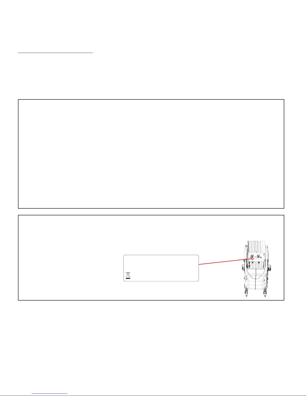
LOCATING YOUR SERIAL NUMBER
Your Minn Kota 11-character serial number is very important. It helps to determine the specifi c model and year of manufacture. When contacting
Consumer Service or registering your product, you will need to know your product’s serial number. We recommend that you write the serial number
down in the space provided below so that you have it available for future reference.
The serial number on your Vantage is located on
the inside of the main transom bracket
EXAMPLE
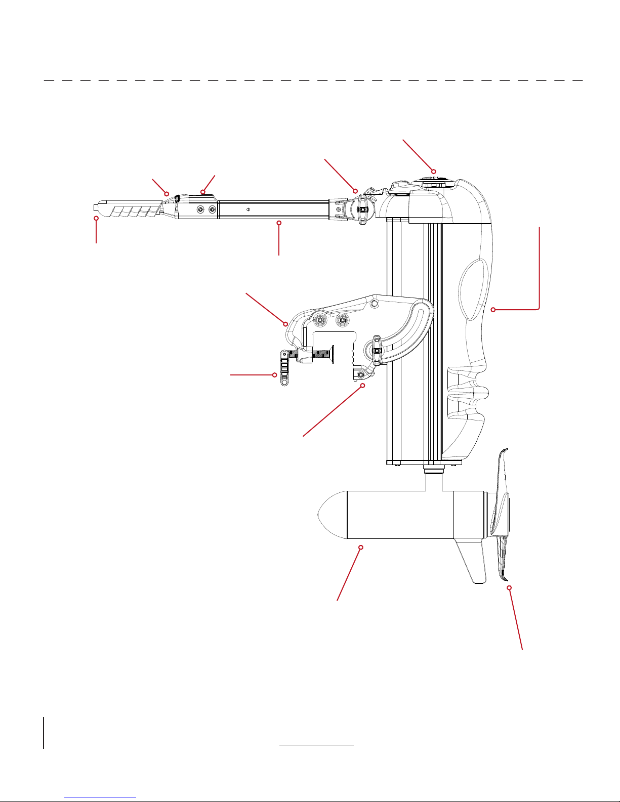
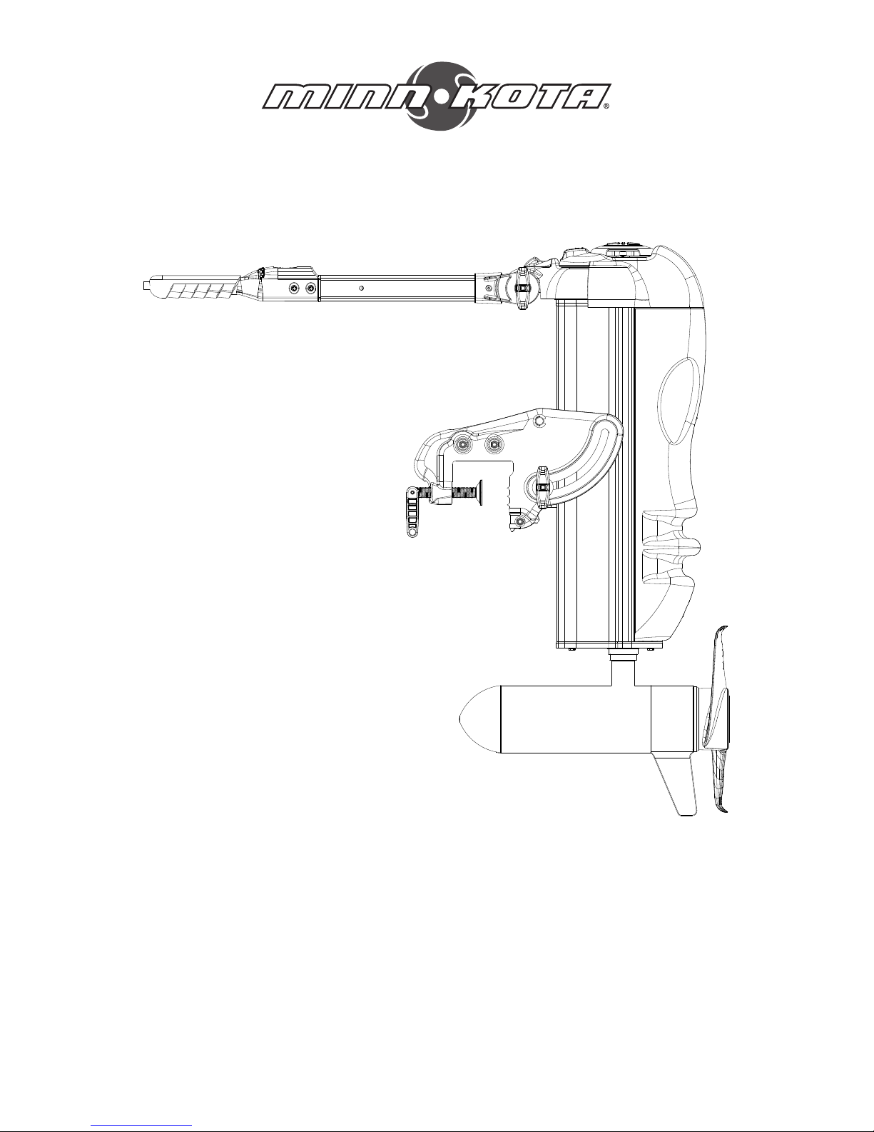
FEATURES
Direction Indicator
4:1 Articulated Steering
On/Off
Speed Control
Breakaway Mounting Bracket
Clamp Screws
Power Trim
Tilt/Extend Tiller Handle
Digital Maximizer
Bracket Tension and
Angle Adjustment Screw
Spe
cifications subject to change without notice.
*This diagram is for reference only and may differ from your actual motor.
Cool, Quiet Power Motor
Weedless Wedge 2 Propeller

INSTALLATION
MOTOR INSTALLATION
With its variable shaft length, the Vantage will fit on most transoms between 14 and 28 inches high.
1. Trailer the boat and park it on a level surface.
2. Locate the Vantage on the boat transom where it will be mounted. The location
choice is important. The Vantage motor lower unit rotates 400°. It must,
therefore, be positioned far enough to the side of the outboard engine along the
transom so that during rotation it will not strike the outboard engine. With the 36V
101 version, you should install the transom extrusion (provided) before you secure
the Vantage to the transom.
TRANSOM EXTRUSION INSTALLATION (101 MODELS ONLY)
a. Set Vantage on transom with clamp screws backed out.
b. Slide extrusion between inside of transom and the clamp screw washers and tighten clamp screws.
c. Attach extrusion to transom with two screws provided. This will require drilling
two appropriate sized pilot holes for the self tapping screws.
3. Set the angle adjustment/tensioning screws (located on the sides of transom
bracket) so the motor is perpendicular to the ground. Hand tighten the screws.
Transom Extrusion
4. Measure from the ground to the bottom of the hull. Measure from ground to the
bottom of the Vantage skeg. Secure the unit so the bottom of the skeg is at one
inch above the bottom of the hull, directly in front of the Vantage (accounting
for the v-shape of the boat hull). Use a 1/2 inch open-end wrench to loosen the
four transom bracket nuts/bolts between the body of Vantage and the transom
bracket. Adjust the body of Vantage to a one-inch level above the transom and
secure. This will position the Vantage lower unit and prop so that, when retracted,
they will clear the bottom of the boat. It may take several attempts to achieve
correct placement.
5. Adjust the handle to a comfortable position.
NOTE: When mounted properly, the Vantage motor lower unit will be out of the water when the boat is on plane. If lower unit
creates water spray when on plane, slightly re-adjust it higher until there is no more water spray.
CAUTION:
• Never operate your motor when it is out of the water.
• Over-tightening the clamp screws can damage the bracket.
WARNING: When raising/lowering motor or operating the tilt mechanism, keep fingers clear of all hinge and
pivot points and all moving parts.
Measure from a level surface

BATTERY WIRING & INSTALLATION
BOAT RIGGING & PRODUCT INSTALLATION
For safety and compliance reasons, we recommend that you follow American Boat and Yacht Council (ABYC) standards when
rigging your boat. Altering boat wiring should be completed by a qualifi ed marine technician. The following specifi cations are for
general guidelines only:
CAUTION: These guidelines apply to general rigging to support your Minn Kota motor. Powering multiple motors or additional
electrical devices from the same power circuit may impact the recommended conductor gauge and circuit breaker size. If you are
using wire longer than that provided with your unit, follow the conductor gauge and circuit breaker sizing table below. If your wire
extension length is more than 25 feet, we recommend that you contact a qualifi ed marine technician.
An over-current protection device (circuit breaker or fuse) must be used. Coast Guard requirements dictate that
each ungrounded current-carrying conductor must be protected by a manually reset, trip-free circuit breaker or fuse. The type
(voltage and current rating) of the fuse or circuit breaker must be sized accordingly to the trolling motor used. The table below gives
recommended guidelines for circuit breaker sizing.
Reference:
United States Code of Federal Regulations: 33 CFR 183 – Boats and Associated Equipment
ABYC E-11: AC and DC Electrical Systems on Boats
CONDUCTOR GAUGE AND CIRCUIT BREAKER SIZING TABLE
Motor Thrust /
Model
30 lb. 30
40 lb., 45 lb. 42 10 AWG 8 AWG 6 AWG 4 AWG 4 AWG
50 lb., 55 lb. 50 60 Amp @ 12 VDC 8 AWG 6 AWG 4 AWG 4 AWG 2 AWG
70 lb. 42 50 Amp @ 24 VDC 10 AWG 10 AWG 8 AWG 8 AWG 6 AWG
80 lb. 56 60 Amp @ 24 VDC 8 AWG 8 AWG 8 AWG 6 AWG 6 AWG
101 lb. 46 50 Amp @ 36 VDC 8 AWG 8 AWG 8 AWG 8 AWG 8 AWG
Engine Mount 101 50 60 Amp @ 36 VDC 8 AWG 6 AWG 4 AWG 4 AWG 2 AWG
112 lb. 52 60 Amp @ 36 VDC 8 AWG 8 AWG 8 AWG 8 AWG 8 AWG
Engine Mount 160 116 (2) x 60 Amp @ 24 VDC 2 AWG 2 AWG 2 AWG 2 AWG 2 AWG
E-Drive 40 50 Amp @ 48 VDC 10 AWG 10 AWG 10 AWG 10 AWG 10 AWG
This conductor and circuit breaker sizing table is only valid for the following assumptions:
1. No more than 3 conductors are bundled together inside of a sheath or conduit outside of engine spaces.
2. Each conductor has 105° C temp rated insulation.
3. No more than 5% voltage drop allowed at full motor power based on published product power requirements.
*Wire Extension Length refers to the distance from the batteries to the trolling motor leads.
Max Amp Draw Circuit Breaker
5 feet 10 feet 15 feet 20 feet 25 feet
10 AWG 10 AWG 8 AWG 6 AWG 4 AWG
50 Amp @ 12 VDC
Wire Extension Length *
BATTERY WIRING & INSTALLATION
SELECTING THE CORRECT BATTERIES
The motor will operate with any lead acid, deep cycle marine 12 volt battery/batteries. For best results, use a deep cycle, marine battery
with at least a 105 ampere hour rating. Maintain battery at full charge. Proper care will ensure having battery power when you need
it, and will signifi cantly improve the battery life. Failure to recharge lead-acid batteries (within 12-24 hours) is the leading cause of
premature battery failure. Use a multi-stage charger to avoid overcharging. We off er a wide selection of chargers to fi t your charging
needs. If you are using a crank battery to start a gasoline outboard, we recommend that you use a separate deep cycle marine battery/
batteries for your Minn Kota trolling motor.
Advice Regarding Batteries:
• Never connect the (+) and the (–) terminals of the battery together. Take care that no metal object can fall onto the battery and short
the terminals. This would immediately lead to a short and extreme fi re danger.
• It is highly recommended that a circuit breaker or fuse be used with this trolling motor. Refer to “Conductor Gauge and Circuit Breaker
Sizing Table” in the previous section to fi nd the appropriate circuit breaker or fuse for your motor. For motors requiring a 60-amp
breaker, the Minn Kota MKR-19 60-amp circuit breaker is recommended.
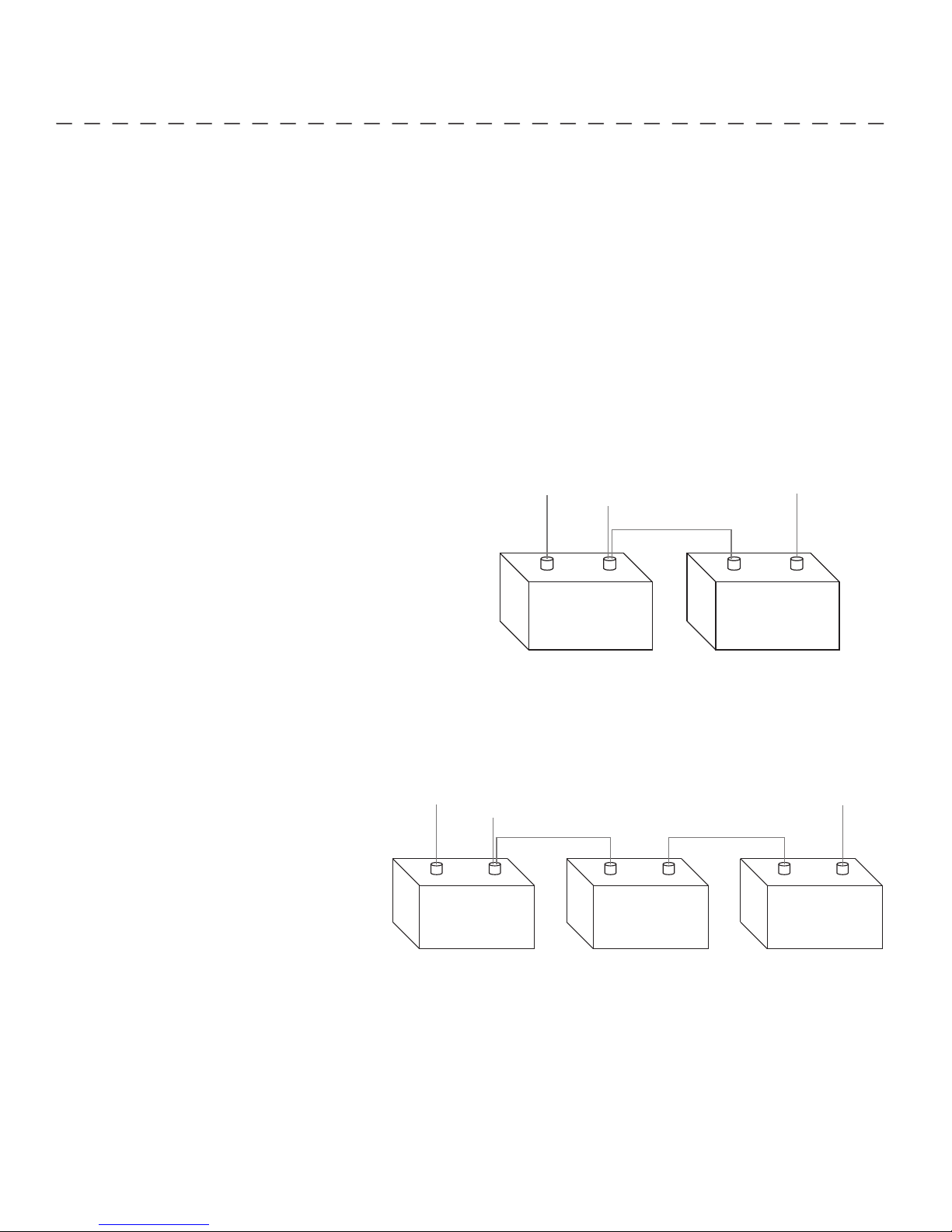
CONNECTING THE BATTERIES IN SERIES (IF REQUIRED FOR YOUR MOTOR)
24 VOLT SYSTEMS:
1. Make sure that the motor is switched off (speed selector on “0”).
2. Two 12 volt batteries are required.
3. The batteries must be wired in series, only as directed in wiring
diagram, to provide 24 volts.
To trolling motor negative
Yellow Lead
24 Volt Connection
a. Connect the connector cable supplied with the
motor to positive (+) terminal of battery 1 and
to negative (–) terminal of battery 2.
b. Connect positive (+) red lead to positive
Neg - Neg -Pos + Pos +
(+) terminal on battery 2.
c. Connect the yellow (+) lead to positive
(+) terminal on battery 1.
d. Connect negative (–) black lead to
Battery #1 (Low Side)
24 Volt Series Connection
negative (–) terminal of battery 1.
4. For safety reasons do not switch the motor on until the propeller is in the water. If installing a leadwire plug, observe proper polarity
and follow instructions in your boat owner’s manual. See wiring diagram on following pages.
+24 Volts to trolling motor
positive (or circuit breaker)
Battery #2 (High Side)
36 VOLT SYSTEMS:
1. Make sure that the motor is switched off (speed selector on “0”).
2. Three 12 volt batteries are required.
3. The batteries must be wired in series, only as
directed in wiring diagram, to provide 36 volts.
a. Connect the connector cable supplied with
the motor to positive (+) terminal of battery
To trolling motor negative
Yellow Lead
24 Volt Connection 36 Volt Connection
+36 Volts to trolling motor
positive (or circuit breaker)
1 and to negative (–) terminal of battery 2.
b. Connect positive (+) red lead to
positive (+) terminal on battery 3.
c. Connect the yellow (+) lead to
positive (+) terminal on battery 1.
d. Connect negative (–) black lead to
negative (–) terminal of battery 1.
4. For safety reasons do not switch the motor on
Neg - Neg - Neg -Pos + Pos + Pos +
Battery #1 (Low Side)
Battery #2 Battery #3 (High Side)
36 Volt Series Connection
until the propeller is in the water. If installing a leadwire plug, observe proper polarity and follow instructions in your boat owner’s
manual. See wiring diagram on following pages.
CAUTION
• Improper wiring of 24/36 volt systems could cause battery explosion!
• Keep leadwire wing nut connection tight and solid to battery terminals.
• Locate battery in a ventilated compartment.
• For safety reasons, disconnect the motor from the battery or batteries when the motor is not in use or while
the battery/batteries are being charged.
 Loading...