

MINN KOTA Terrova 70, Terrova 50, Terrova 80, Terrova 101, Terrova 112 User Manual
...
BOW-MOUNT TROLLING MOTOR
TERROVA
USER MANUAL
CE MASTER USER MANUAL (FOR CE/C-TICK CERTIFIED MODELS)
Made by Minn Kota
Johnson Outdoors
Marine Electronics, Inc.
121 Power Drive
Mankato, MN 56001 USA
Trolling Motors
Produced in 2012
Terrova 55 48”
MODEL 1358800
SER NO M365 MK12345
Conforms to 89/336/EEC (EMC) under standards EN 55022A, EN 50082-2 since 1996 LN V9677264
THANK YOU
Thank you for choosing Minn Kota. We believe that you should spend more time fi shing and less time positioning your boat.
That’s why we build the smartest, toughest, most intuitive trolling motors on the water. Every aspect of a Minn Kota trolling motor
is thought out and rethought until it’s good enough to bear our name. Countless hours of research and testing provide you the
Minn Kota advantage that can truly take you “Anywhere. Anytime.” We don’t believe in shortcuts. We are Minn Kota. And we are
never done helping you catch more fi sh.
REMEMBER TO KEEP YOUR RECEIPT AND IMMEDIATELY REGISTER YOUR TROLLING MOTOR.
A registration card is enclosed or you can complete registration on our website at minnkotamotors.com.
NOTE: Do not return your Minn Kota motor to your retailer. Your retailer is not authorized to repair or replace this unit. You may obtain service
by: calling Minn Kota at (800) 227-6433; returning your motor to the Minn Kota Factory Service Center; sending or taking your motor to any
Minn Kota authorized service center. A list of authorized service centers is available on our website, at minnkotamotors.com. Please include proof of
purchase, serial number and purchase date for warranty service with any of the above options.
Please thoroughly read this user manual. Follow all instructions and heed all safety and cautionary notices below. Use of this motor is only
permitted for persons that have read and understood these user instructions. Minors may use this motor only under adult supervision.
ATTENTION: Never run the motor out of the water, as this may result in injuries from the rotating propeller. The motor should be disconnected from
the power source when it is not in use or is off the water. When connecting the power-supply cables of the motor to the battery, ensure that they are
not kinked or subject to chafe and route them in such a way that persons cannot trip over them. Before using the motor make sure that the insulation
of the power cables is not damaged. Disregarding these safety precautions may result in electric shorts of battery(s) and/or motor. Always disconnect
motor from battery(s) before cleaning or checking the propeller. Avoid submerging the complete motor as water may enter the lower unit through
control head and shaft. If the motor is used while water is present in the lower unit considerable damage to the motor can occur. This damage will not
be covered by warranty.
CAUTION: Take care that neither you nor other persons approach the turning propeller too closely, neither with body parts nor with objects. The
motor is powerful and may endanger or injure you or others. While the motor is running watch out for persons swimming and for fl oating objects.
Persons whose ability to run the motor or whose reactions are impaired by alcohol, drugs, medication, or other substances are not permitted to use
this motor. This motor is not suitable for use in strong currents. The constant noise pressure level of the motor during use is less than 70dB(A). The
overall vibration level does not exceed 2,5m/sec2.
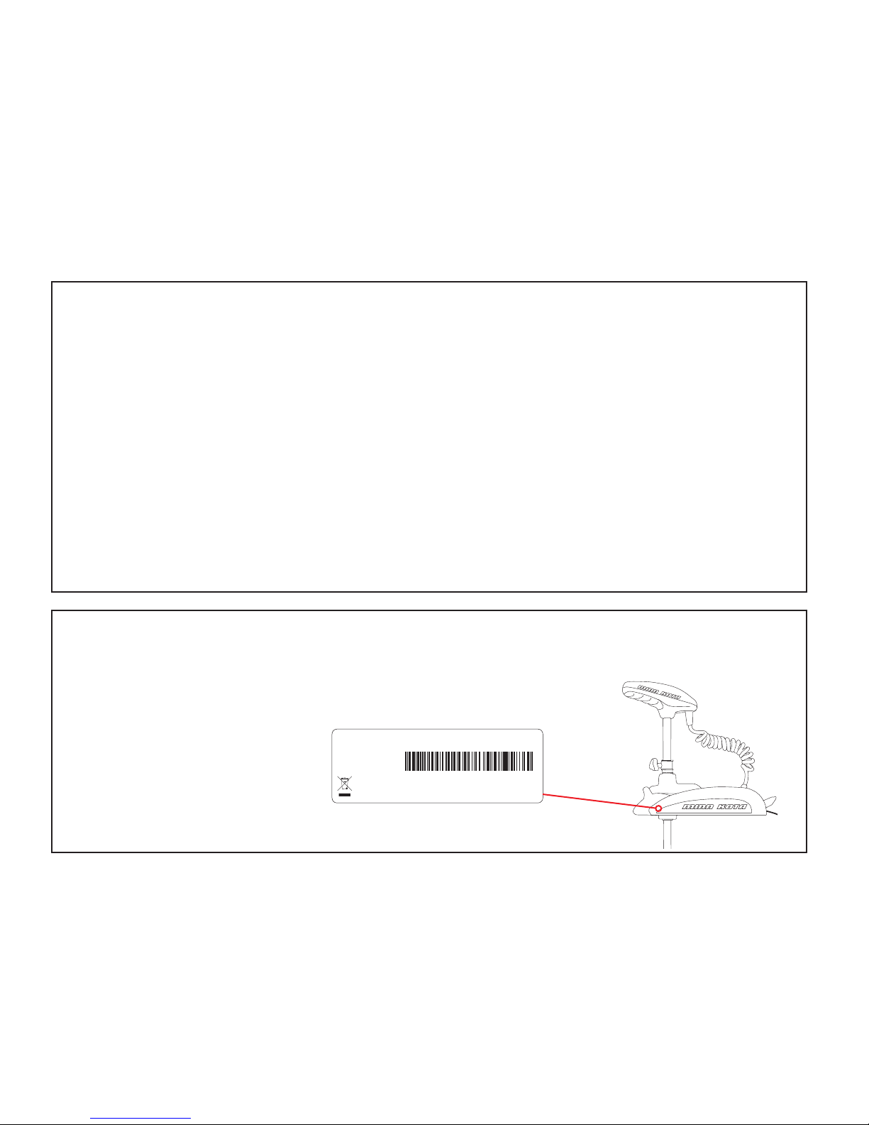
LOCATING YOUR SERIAL NUMBER
Your Minn Kota 11-character serial number is very important. It helps to determine the specifi c model and year of manufacture. When contacting
Consumer Service or registering your product, you will need to know your product’s serial number. We recommend that you write the serial number
down in the space provided below so that you have it available for future reference.
The serial number on your Terrova is located
inside the mount, below the motor rests.
EXAMPLE
Model: _________________________________________________________________________________________________________________________
Serial Number: _______________________________________________________________________________________________________________
Purchase Date: _______________________________________________________________________________________________________________
Store Where Purchased: ____________________________________________________________________________________________________
2 | minnkotamotors.com
©2014 Johnson Outdoors Marine Electronics, Inc.

TABLE OF CONTENTS
Two-Year Limited Warranty 4
Features 5
Mount Installation 6
Battery & Wiring Installation 7-9
Boat Rigging & Product Installation 7
Conductor Gauge and Circuit Breaker Sizing Table 7
Selecting the Correct Batteries 8
Connecting the Batteries 8-9
Push-to-test Battery Meter 9
Motor Wiring Diagram 10
Using The Motor 11-13
Stowing & Deploying 11
AutoPilot Controls 12
Adjusting the Depth of the Motor 12
Installing the External Transducer 13
Using the Foot Pedal 14
Service & Maintenance 15
Troubleshooting 16
Parts Diagram 17
Parts List 18-19
Environmental Compliance Statement 20
Notes 21
©2014 Johnson Outdoors Marine Electronics, Inc.
minnkotamotors.com | 3

TWO-YEAR LIMITED WARRANTY
WARRANTY ON MINN KOTA FRESHWATER TROLLING MOTORS
Johnson Outdoors Marine Electronics, Inc. (“JOME”) extends the following limited warranty to the original retail purchaser only. Warranty coverage is not
transferable.
MINN KOTA LIMITED TWO-YEAR WARRANTY ON THE ENTIRE PRODUCT
JOME warrants to the original retail purchaser only that the purchaser’s new Minn Kota freshwater trolling motor will be materially free from defects in materials
and workmanship appearing within two (2) years after the date of purchase. JOME will (at its option) either repair or replace, free of charge, any parts found by
JOME to be defective during the term of this warranty. Such repair, or replacement shall be the sole and exclusive liability of JOME and the sole and exclusive
remedy of the purchaser for breach of this warranty.
MINN KOTA LIMITED LIFETIME WARRANTY ON COMPOSITE SHAFT
JOME warrants to the original retail purchaser only that the composite shaft of the purchaser’s Minn Kota trolling motor will be materially free from defects in
materials and workmanship appearing within the original purchaser’s lifetime. JOME will provide a new composite shaft, free of charge, to replace any composite
shaft found by JOME to be defective during the term of this warranty. Providing a new composite shaft shall be the sole and exclusive liability of JOME and the
sole and exclusive remedy of the purchaser for breach of this warranty; and purchaser shall be responsible for installing, or for the cost of labor to
install, any new composite shaft provided by JOME.
EXCLUSIONS & LIMITATIONS
This limited warranty does not apply to products that have been used in saltwater or brackish water, commercially or for rental purposes. This limited warranty
does not cover normal wear and tear, blemishes that do not aff ect the operation of the product, or damage caused by accidents, abuse, alteration, modifi cation,
shipping damages, acts of God, negligence of the user or misuse, improper or insuffi cient care or maintenance. DAMAGE CAUSED BY THE USE OF
OTHER REPLACEMENT PARTS NOT MEETING THE DESIGN SPECIFICATIONS OF THE ORIGINAL PARTS WILL NOT BE COVERED BY
THIS LIMITED WARRANTY. The cost of normal maintenance or replacement parts which are not in breach of the limited warranty are the responsibility
of the purchaser. Prior to using products, the purchaser shall determine the suitability of the products for the intended use and assumes all related risk and
liability. Any assistance JOME provides to or procures for the purchaser outside the terms, limitations or exclusions of this limited warranty will not constitute
a waiver of the terms, limitations or exclusions, nor will such assistance extend or revive the warranty. JOME will not reimburse the purchaser for any expenses
incurred by the purchaser in repairing, correcting or replacing any defective products or parts, except those incurred with JOME’s prior written permission.
JOME’S AGGREGATE LIABILITY WITH RESPECT TO COVERED PRODUCTS IS LIMITED TO AN AMOUNT EQUAL TO THE PURCHASER’S
ORIGINAL PURCHASE PRICE PAID FOR SUCH PRODUCT.
MINN KOTA SERVICE INFORMATION
To obtain warranty service in the U.S., the product believed to be defective, and proof of original purchase (including the date of purchase), must be presented
to a Minn Kota Authorized Service Center or to Minn Kota’s factory service center in Mankato, MN. Any charges incurred for service calls, transportation or
shipping/freight to/from the Minn Kota Authorized Service Center or factory, labor to haul out, remove, re-install or re-rig products removed for warranty service,
or any other similar items are the sole and exclusive responsibility of the purchaser. Products purchased outside of the U.S. must be returned prepaid with
proof of purchase (including the date of purchase and serial number) to any Authorized Minn Kota Service Center in the country of purchase. Warranty service
can be arranged by contacting a Minn Kota Authorized Service Center or by contacting the factory at 1-800-227-6433 or email service@minnkotamotors.com.
Products repaired or replaced will be warranted for the remainder of the original warranty period [or for 90 days from the date of repair
or replacement, whichever is longer]. For any product that is returned for warranty service that JOME fi nds to be not covered by or not
in breach of this limited warranty, there will be a billing for services rendered at the prevailing posted labor rate and for a minimum of at
least one hour.
NOTE: Do not return your Minn Kota product to your retailer. Your retailer is not authorized to repair or replace products.
THERE ARE NO EXPRESS WARRANTIES OTHER THAN THESE LIMITED WARRANTIES. IN NO EVENT SHALL ANY IMPLIED
WARRANTIES INCLUDING ANY IMPLIED WARRANTIES OF MERCHANTABILITY OR FITNESS FOR PARTICULAR PURPOSE, EXTEND
BEYOND THE DURATION OF THE RELEVANT EXPRESS LIMITED WARRANTY. IN NO EVENT SHALL JOME BE LIABLE FOR PUNITIVE,
INDIRECT, INCIDENTAL, CONSEQUENTIAL OR SPECIAL DAMAGES. Without limiting the foregoing, JOME assumes no responsibility for
loss of use of product, loss of time, inconvenience or other damage.
Some states do not allow limitations on how long an implied warranty lasts or the exclusion or limitation of incidental or consequential damages, so the above
limitations and/or exclusions may not apply to you. This warranty gives you specifi c legal rights and you may also have other legal rights which vary from state
to state.
4 | minnkotamotors.com
©2014 Johnson Outdoors Marine Electronics, Inc.
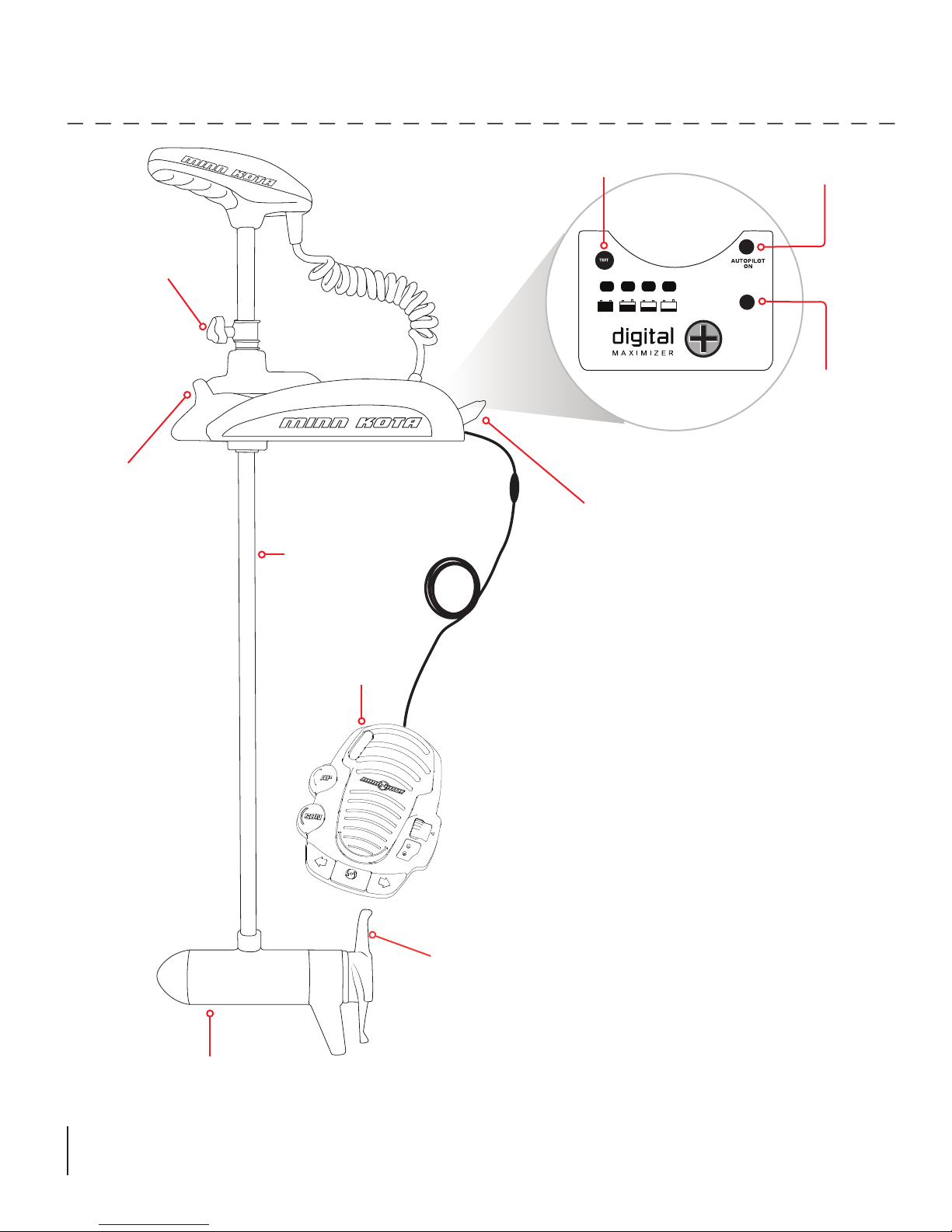
FEATURES
Adjustable Depth Collar
Fall Away Ramps
Lifetime
Warranty Flexible
Composite Shaft
Push-to-Test Battery Meter
Stow/Deploy Lever
AutoPilot Indicator
(functional on equipped motors only)
System Ready
Indicator
Cool Quiet
Power Motor
Low Profile
Foot Pedal
Weedless Wedge 2 Propeller
Specifications subject to change without notice.
*This diagram is for reference only and may differ from your actual motor.
©2014 Johnson Outdoors Marine Electronics, Inc.
minnkotamotors.com | 5
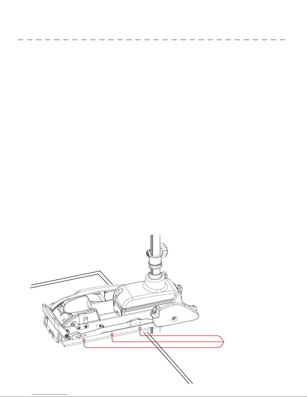
MOUNT INSTALLATION
TOOLS AND RESOURCES REQUIRED:
• #3 Phillips Screw Driver
• Drill
• 9/32” Drill Bit
• 7/16” Box End Wrench
• A second person to help with the installation
1. Remove the four sideplate screws. Remove the right sideplate and swing the left sideplate out and away from the base
extrusion.
2. Place the motor on the bow of the boat in the deployed position.
a. We recommend that the motor be mounted as close to the centerline of the boat as possible.
b. Make sure that the area under the mounting location is clear and unobstructed
for drilling and accessible for you to attach nuts and washers.
c. Make sure the mount is positioned so that the shaft is out beyond the rub rail of the boat by 1-1/2”. The lower unit, as it is
lowered into the water or raised into the boat, must not encounter any obstructions.
CAUTION: Make sure the motor is mounted on a level surface and is not connected to
a power source. Use the rubber washers to create a leve surface if necessary.
3. Once in position, mark four of the six holes (two on each side) provided in the bow mount base for drilling. If possible, use the
four holes that are farthest apart. Drill through the marked holes using the 9/32” drill bit.
4. Mount the plate to the bow using the provided bolts, nuts, and washers.
5. Replace the sideplates and sideplate screws.
Mounting Holes
(3 Per Side)
6 | minnkotamotors.com
©2014 Johnson Outdoors Marine Electronics, Inc.

BATTERY WIRING & INSTALLATION
BOAT RIGGING & PRODUCT INSTALLATION
For safety and compliance reasons, we recommend that you follow American Boat and Yacht Council (ABYC) standards when
rigging your boat. Altering boat wiring should be completed by a qualifi ed marine technician. The following specifi cations are for
general guidelines only:
CAUTION: These guidelines apply to general rigging to support your Minn Kota motor. Powering multiple motors or additional
electrical devices from the same power circuit may impact the recommended conductor gauge and circuit breaker size. If you are
using wire longer than that provided with your unit, follow the conductor gauge and circuit breaker sizing table below. If your wire
extension length is more than 25 feet, we recommend that you contact a qualifi ed marine technician.
An over-current protection device (circuit breaker or fuse) must be used. Coast Guard requirements dictate that
each ungrounded current-carrying conductor must be protected by a manually reset, trip-free circuit breaker or fuse. The type
(voltage and current rating) of the fuse or circuit breaker must be sized accordingly to the trolling motor used. The table below gives
recommended guidelines for circuit breaker sizing.
Reference:
United States Code of Federal Regulations: 33 CFR 183 – Boats and Associated Equipment
ABYC E-11: AC and DC Electrical Systems on Boats
CONDUCTOR GAUGE AND CIRCUIT BREAKER SIZING TABLE
Motor Thrust /
Model
30 lb. 30
40 lb., 45 lb. 42 10 AWG 8 AWG 6 AWG 4 AWG 4 AWG
50 lb., 55 lb. 50 60 Amp @ 12 VDC 8 AWG 6 AWG 4 AWG 4 AWG 2 AWG
70 lb. 42 50 Amp @ 24 VDC 10 AWG 10 AWG 8 AWG 8 AWG 6 AWG
80 lb. 56 60 Amp @ 24 VDC 8 AWG 8 AWG 8 AWG 6 AWG 6 AWG
101 lb. 46 50 Amp @ 36 VDC 8 AWG 8 AWG 8 AWG 8 AWG 8 AWG
Engine Mount 101 50 60 Amp @ 36 VDC 8 AWG 6 AWG 4 AWG 4 AWG 2 AWG
112 lb. 52 60 Amp @ 36 VDC 8 AWG 8 AWG 8 AWG 8 AWG 8 AWG
Engine Mount 160 116 (2) x 60 Amp @ 24 VDC 2 AWG 2 AWG 2 AWG 2 AWG 2 AWG
E-Drive 40 50 Amp @ 48 VDC 10 AWG 10 AWG 10 AWG 10 AWG 10 AWG
This conductor and circuit breaker sizing table is only valid for the following assumptions:
1. No more than 3 conductors are bundled together inside of a sheath or conduit outside of engine spaces.
2. Each conductor has 105° C temp rated insulation.
3. No more than 5% voltage drop allowed at full motor power based on published product power requirements.
*Wire Extension Length refers to the distance from the batteries to the trolling motor leads.
Max Amp Draw Circuit Breaker
5 feet 10 feet 15 feet 20 feet 25 feet
10 AWG 10 AWG 8 AWG 6 AWG 4 AWG
50 Amp @ 12 VDC
Wire Extension Length *
©2014 Johnson Outdoors Marine Electronics, Inc.
minnkotamotors.com | 7
BATTERY WIRING & INSTALLATION
SELECTING THE CORRECT BATTERIES
The motor will operate with any lead acid, deep cycle marine 12 volt battery/batteries. For best results, use a deep cycle, marine
battery with at least a 105 ampere hour rating. Maintain battery at full charge. Proper care will ensure having battery power
when you need it, and will signifi cantly improve the battery life. Failure to recharge lead-acid batteries (within 12-24 hours) is the
leading cause of premature battery failure. Use a multi-stage charger to avoid overcharging. We off er a wide selection of chargers
to fi t your charging needs. If you are using a crank battery to start a gasoline outboard, we recommend that you use a separate
deep cycle marine battery/batteries for your Minn Kota trolling motor.
Advice Regarding Batteries:
• Never connect the (+) and the (–) terminals of the same battery together. Take care that no metal object can fall onto the
battery and short the terminals. This would immediately lead to a short and extreme fi re danger.
• It is highly recommended that a circuit breaker or fuse be used with this trolling motor. Refer to “Conductor Gauge and Circuit
Breaker Sizing Table” in the previous section to fi nd the appropriate circuit breaker or fuse for your motor. For motors requiring
a 60-amp breaker, the Minn Kota MKR-19 60-amp circuit breaker is recommended.
CONNECTING THE BATTERIES
12 VOLT SYSTEMS:
1. Make sure that the motor is switched off (speed selector on “OFF” or “0”).
2. Connect positive ( + ) red lead to positive ( + ) battery terminal.
3. Connect negative ( – ) black lead to negative ( – ) battery terminal.
4. For safety reasons do not switch the motor on until the propeller is in the water.
CAUTION:
For safety reasons, disconnect the motor from the battery/batteries when the motor is not in use or while the
battery/batteries are being charged.
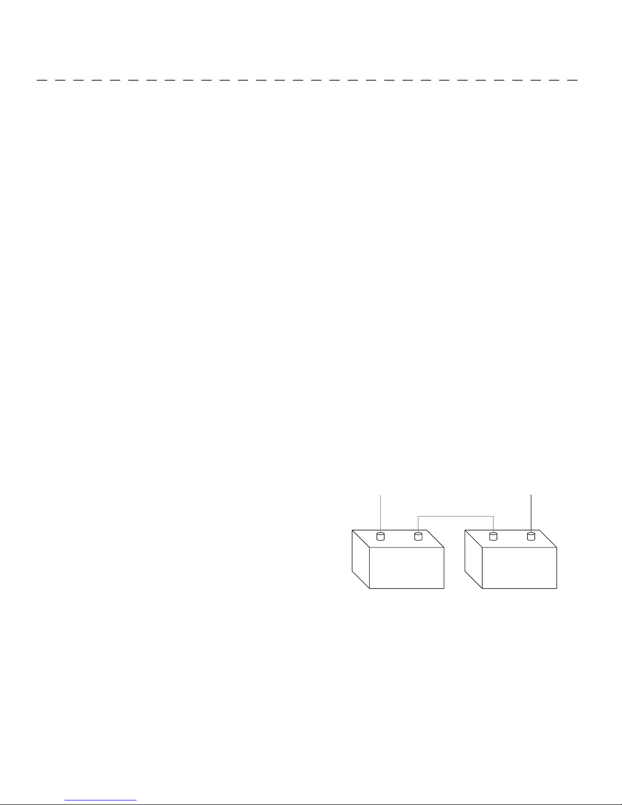
CONNECTING THE BATTERIES IN SERIES (IF REQUIRED FOR YOUR MOTOR)
24 VOLT SYSTEMS:
1. Make sure that the motor is switched off (speed selector on “0”).
2. Two 12 volt batteries are required.
3. The batteries must be wired in series, only as directed in wiring
To trolling motor negative
24 Volt Connection
diagram, to provide 24 volts.
a. Connect a connector cable to the positive ( + ) terminal of
battery 1 and to the negative ( – ) terminal of battery 2.
Neg - Neg -Pos + Pos +
b. Connect positive ( + ) red motor lead to
positive ( + ) terminal on battery 2.
Battery #1 (Low Side)
c. Connect negative ( – ) black motor lead to
negative ( – ) terminal of battery 1.
24 Volt Series Connection
4. For safety reasons do not switch the motor on until the propeller is in the water. If installing a leadwire plug, observe proper
polarity and follow instructions in your boat owner’s manual. See wiring diagram on following pages.
CAUTION
• For safety reasons, disconnect the motor from the battery or batteries when the motor is not in use or while
the battery/batteries are being charged.
• Improper wiring of 24/36 volt systems could cause battery explosion!
• Keep leadwire wing nut connections tight and solid to battery terminals.
• Locate battery in a ventilated compartment.
+24 Volts to trolling motor
positive (or circuit breaker)
Battery #2 (High Side)
8 | minnkotamotors.com
©2014 Johnson Outdoors Marine Electronics, Inc.
BATTERY WIRING & INSTALLATION
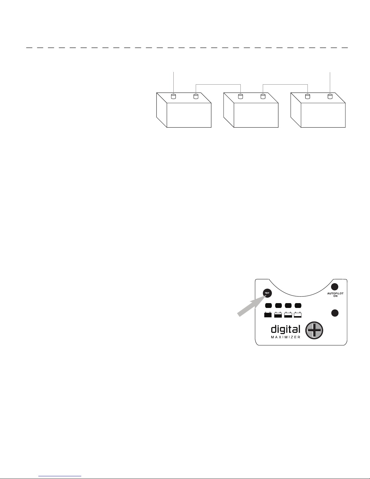
36 VOLT SYSTEMS:
1. Make sure that the motor is switched off
(speed selector on “0”).
2. Three 12 volt batteries are required.
To trolling motor negative
24 Volt Connection 36 Volt Connection
+36 Volts to trolling motor
positive (or circuit breaker)
3. The batteries must be wired in series, only as
directed in wiring diagram, to provide 36 volts.
a. Connect a connector cable to the positive
( + ) terminal of battery 1 and to the
negative ( – ) terminal of battery 2 and
another connector cable from the positive
( + ) terminal of battery 2 to the negative
Neg - Neg - Neg -Pos + Pos + Pos +
Battery #1 (Low Side)
Battery #2 (Middle) Battery #3 (High Side)
36 Volt Series Connection
( – ) terminal of battery of battery 3.
b. Connect positive ( + ) red motor lead to positive ( + ) terminal on battery 3.
c. Connect negative ( – ) black motor lead to negative ( – ) terminal of battery 1.
4. For safety reasons do not switch the motor on until the propeller is in the water. If installing a leadwire plug, observe proper
polarity and follow instructions in your boat owner’s manual. See wiring diagram on following pages.
CAUTION
• Improper wiring of 24/36 volt systems could cause battery explosion!
• Keep leadwire wing nut connections tight and solid to battery terminals.
• Locate battery in a ventilated compartment.
• For safety reasons, disconnect the motor from the battery or batteries when the motor is not in use or while
the battery/batteries are being charged.
PUSH-TO-TEST BATTERY METER
This motor is equipped with a “push to test” battery meter. The LED provides an accurate
display of the remaining charge in the battery. It is only accurate when the motor is off .
The meter reads as:
• One light indicates recharge.
• Two lights indicate low charge.
• Three lights indicate good charge.
• Four lights indicate full charge.
©2014 Johnson Outdoors Marine Electronics, Inc.
minnkotamotors.com | 9
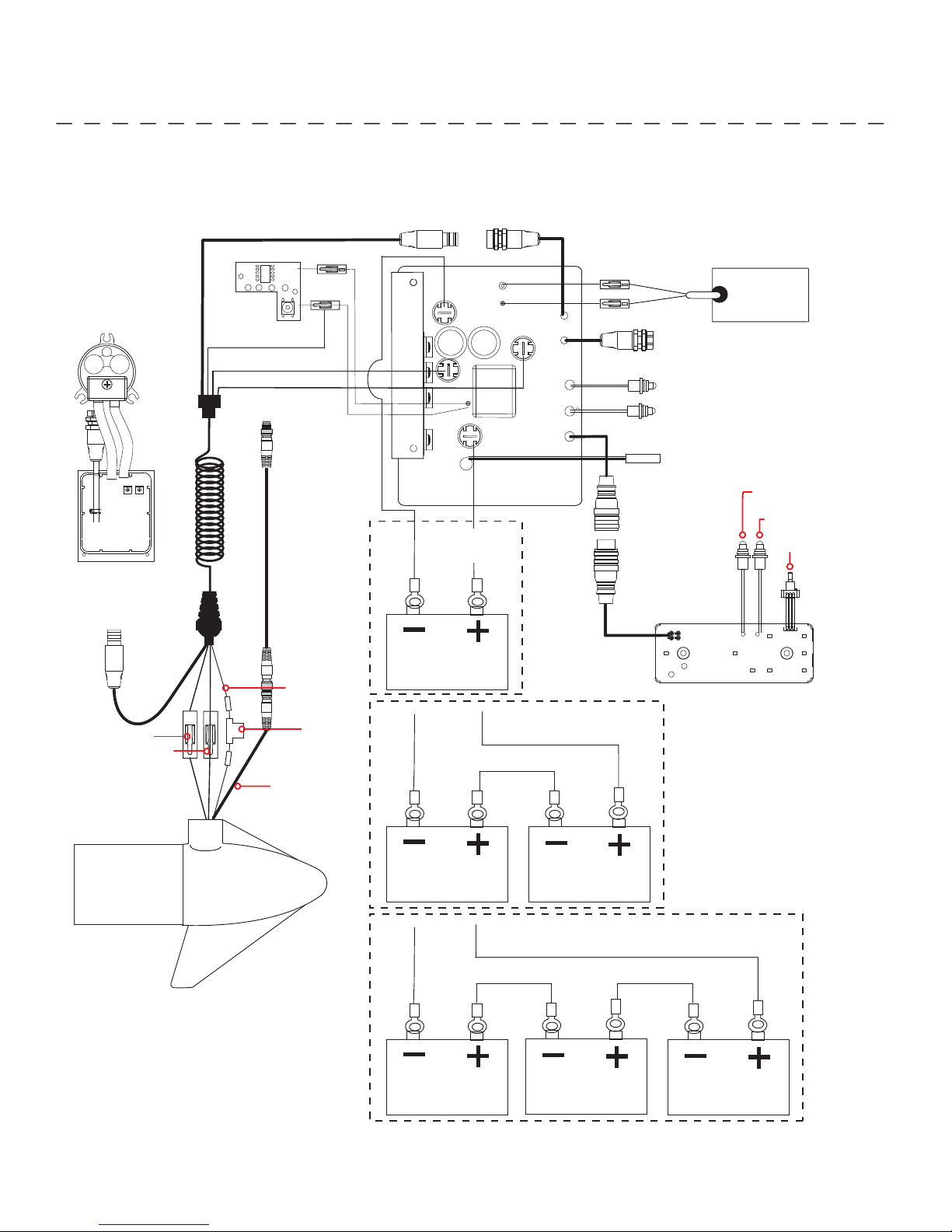
MOTOR WIRING DIAGRAM
NOTE: This is a universal, multi-voltage diagram. Double check your motor's voltage for proper connections. Over-Current
Protection Devices not shown in this illustration.
COMPASS
SENSOR
BOARD
AUTOPILOT
ON EQUIPPED MOTORS ONLY
ACCESSORY PLUG
BATTERY GAUGE
BROWN
BLACK M-
RED M+
COIL CORD
UNIVERSAL SONAR 2 EXTENSION WIRE*
BROWN*
RED
BLACK
BLACK B-
M-
BATTERY 1
CONTROL BOARD
B-
B+
RED B+
12v
M+
WHITE
BLACK
STEERING MOTOR
ACCESSORY PLUG
AUTOPILOT INDICATOR, RED
SYSTEM READY, INDICATOR, GREEN
REED SWITCH
AUTOPILOT INDICATOR, RED
MOMENTARY/CONSTANT
INDICATOR, GREEN
SPEED ADJUSTMENT
KNOB
FOOT PEDAL
CONTROL BOARD
RED M+
BLACK M-
MOTOR
* UNIVERSAL SONAR2 MOTORS ONLY
FUSE*
UNIVERSAL
SONAR 2 WIRE*
24v
BATTERY 1 BATTERY 2
36v
BATTERY 1 BATTERY 2 BATTERY 3
10 | minnkotamotors.com
©2014 Johnson Outdoors Marine Electronics, Inc.
USING & ADJUSTING THE MOTOR
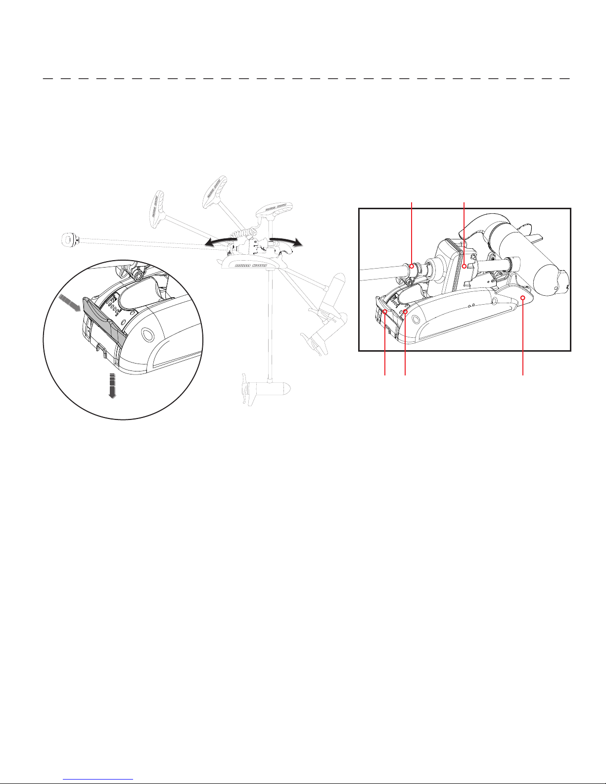
STOWING AND DEPLOYING THE MOTOR
WARNING:
When raising or lowering the motor, keep fingers clear of all hinge and pivot points and all moving parts.
STOW/DEPLOY LEVER OPERATION:
1. Push in
2. Push down
1
2
GENERAL
System Ready (green LED): The motor is equipped with a system ready indicator. Indicator light will be on when motor is
deployed and power is applied to the motor. When the motor is properly stowed the indicator light will go off indicating all power
has been turned off to the motor. If this indicator light does not come on when deployed, check that motor is connected to battery
properly and motor is completely deployed. If indicator light does not go off when stowed, be sure that stow/deploy lever is fully
latched and locked into the stowed position.
Stow/Deploy
Depth Collar Steering Housing
Fall Away Ramps
Lever
System Ready
Indicator
TO DEPLOY THE MOTOR
Push in and rotate the stow/deploy lever down. Gently slide the motor out from the ramps. Lower the motor to the desired depth,
making sure that it clicks into a secure, verticle position. The System Ready indicator light (green) will be lit, indicating motor is
ready for operation.
TO STOW THE MOTOR
Push and hold the stow/deploy lever down. Gently tilt and pull the composite shaft or control head until the motor engages the
motor ramps. Motor should rest on the motor ramps and lock into place. The stow/deploy lever should latch automatically into the
stowed position. The system ready indicator light (green) MUST go off for the motor to be stowed properly.
TRANSPORTATION
In conditions where the stowed motor is subject to high levels of shock or vibration, ensure the motor is securely stowed. Move
the depth collar snug against the steering motor and tighten.
©2014 Johnson Outdoors Marine Electronics, Inc.
minnkotamotors.com | 11
USING & ADJUSTING THE MOTOR
AUTOPILOT™ CONTROLS
(ON AUTOPILOT EQUIPPED MOTORS ONLY)
™
The Minn Kota AutoPilot
you want to go. Each time the wind or water current moves the boat off course, the AutoPilot senses the change and steers itself
back to the original heading. The AutoPilot direction is set every time a steering change is made. To change direction, steer until
the control head points to the desired course. The AutoPilot will pull the bow of the boat around and correct automatically until
the boat is moving in the direction you chose.
1. This unit has an automatic steering shutdown for safety. In conditions where an obstruction prevents the trolling motor from
turning, or in extremely windy conditions, the automatic steering may stop. Any steering input will reset the system to normal.
2. When the AutoPilot is on and the trolling motor is pulled out of the water to the stow position, the steering motor will continue
to run until the motor is stowed properly. Once the motor is stowed properly, AutoPilot will turn off and the System Ready
indicator will go off .
3. This unit uses a magnetic compass to detect direction of travel. The compass can be adversely aff ected by magnets or large,
ferrous metal objects near (within 12” of) the trolling motor control head.
uses a magnetic compass and a microprocessor chip to keep the trolling motor pointed in the direction
4. After steering to a new direction, there is a short delay before the direction is locked in to allow the compass to stabilize.
5. Obstructions on the propeller may cause excessive vibration of the motor head. This vibration can cause the compass to
wander and erratic steering to occur. Clear the obstruction to return the motor to normal operation.
6. When broad speed changes are made, the motor heading may change slightly. This is normal.
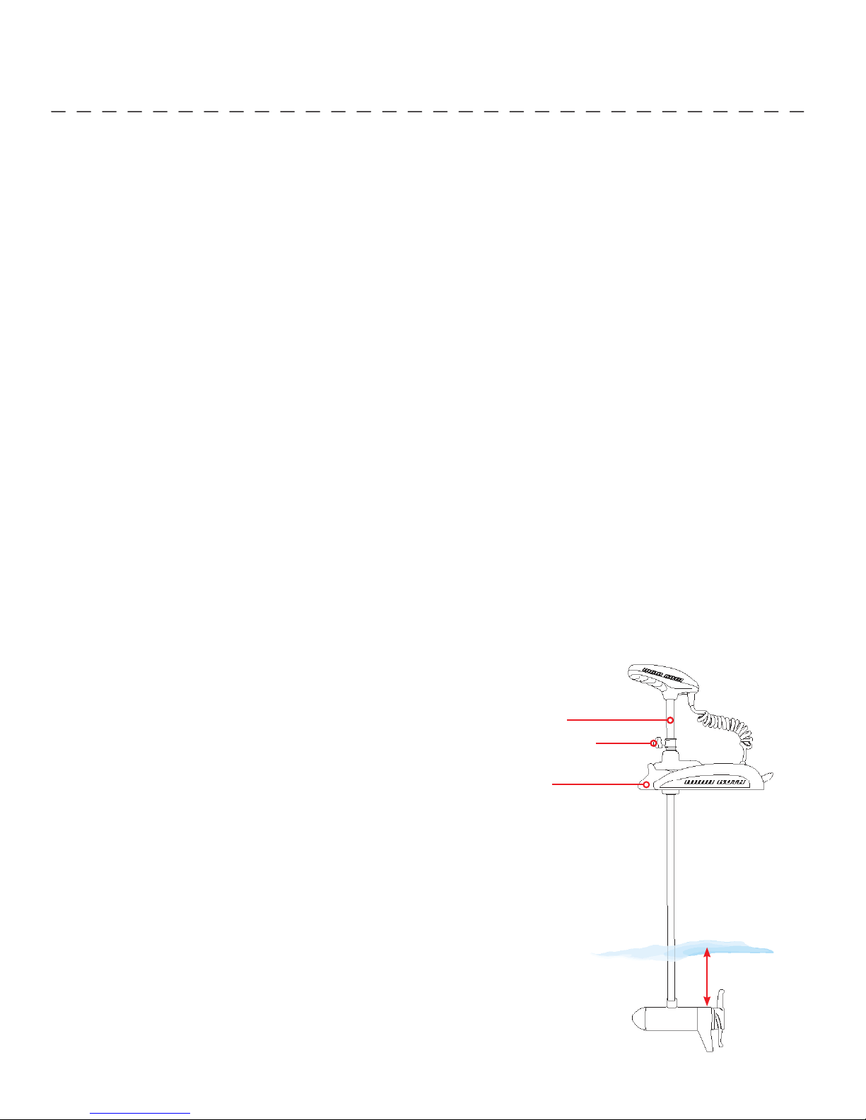
ADJUSTING THE DEPTH OF THE MOTOR
When setting the depth be sure the top of the motor is submerged
at least 12” to avoid churning or agitation of surface water. The
propeller must be completely submerged.
1. With the motor deployed, fi rmly grasp the composite shaft above
the mount.
2. Loosen the adjustable depth collar until the shaft slides freely.
3. Raise or lower the motor to the desired depth.
4. Turn the motor control head to the desired position.
Composite Shaft
Adjustable Depth Collar
Motor Mount
5. Tighten adjustable depth collar to secure the motor in place.
12 | minnkotamotors.com
12” Minimum Depth
©2014 Johnson Outdoors Marine Electronics, Inc.
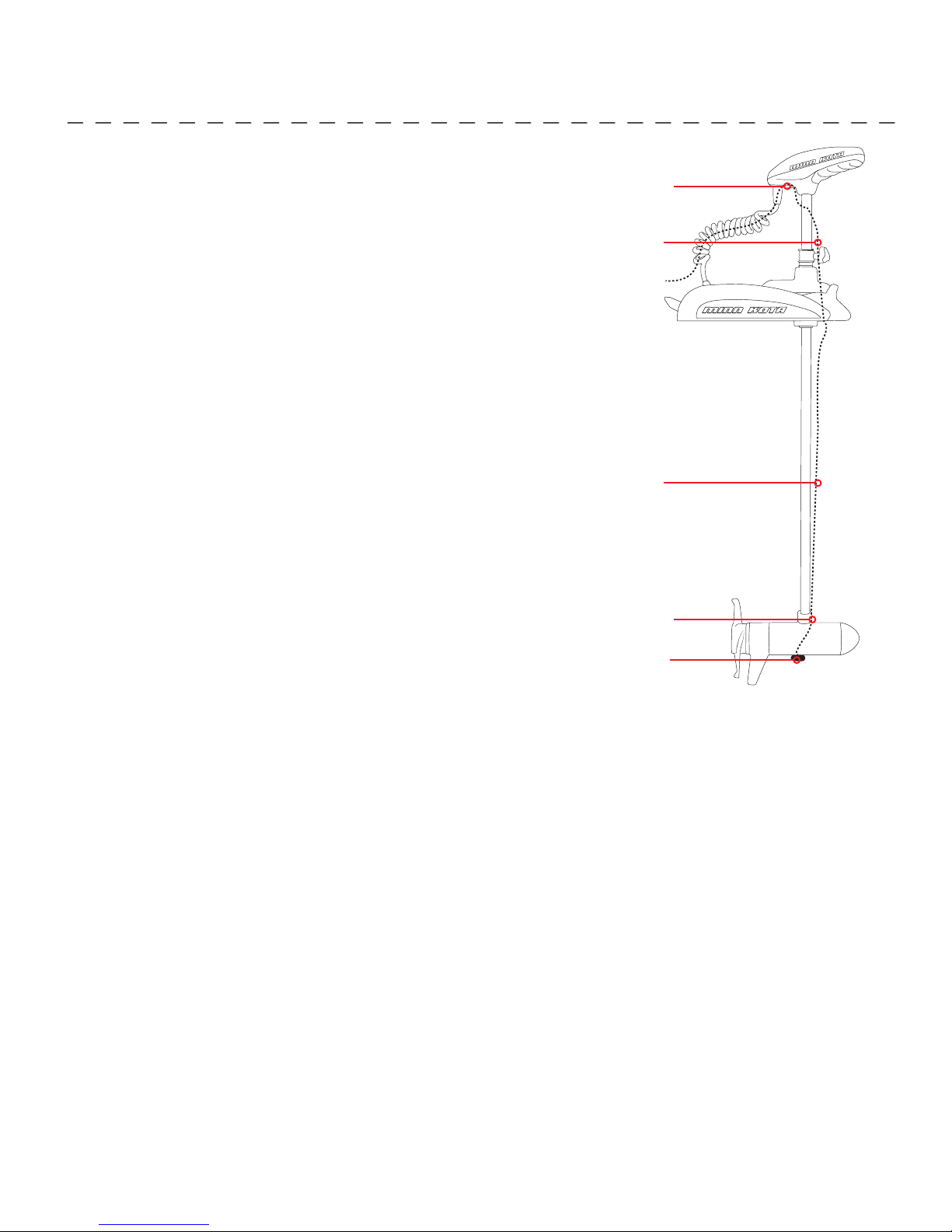
INSTALLING THE EXTERNAL TRANSDUCER
An external sonar transducer can be installed onto the motor as shown.
1. Transducer cables should be routed through the coil cable as
depicted in the illustration to the right.
2. Leave enough slack for proper stow and deploy.
3. Mount transducer according to transducer instructions.
Note: An external transducer is not included with your trolling motor.
Your trolling motor may be pre-installed with a Universal Sonar 2
transducer system. In this case, the transducer is integrated into the
motor unit.
For compatibility and more information on Universal Sonar 2, please
visit minnkotamotors.com/us2.
USING & ADJUSTING THE MOTOR
Tie wrap cable
Leave slack
Transducer
cable
Leave slack
ACCESSORY RECOMMENDATIONS:
• Minn Kota Transducer Mounting Kit (MKR-15)
Tie wrap cable
Transducer
©2014 Johnson Outdoors Marine Electronics, Inc.
minnkotamotors.com | 13
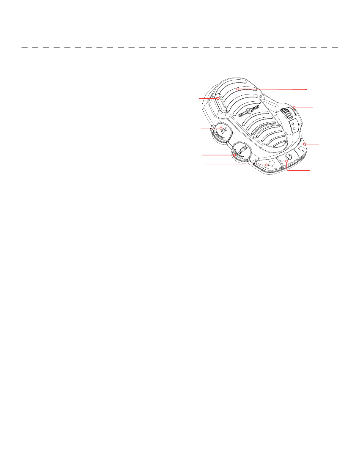
USING THE FOOT PEDAL
All the controls in the foot pedal are easy to operate by either foot or hand. A light touch is all that is necessary.
MOMENTARY
A toe touch on either of the two momentary buttons
turns the propeller on. Let up and the propeller stops.
MOM/CON SWITCH
A toe touch to the Mom/Con button toggles the motor
between momentary and constant. When the motor
Momentary on
AutoPilot
“ON” / “OFF”
Heel/toe
steering
Variable speed
control
is in constant the propeller will run continuously with
out keeping your foot on the pedal. When the motor
is in momentary, a toe touch is required to one of the
momentary on buttons to turn the propeller on. The
Constant On indicator light will be lit when the motor is
Momentary / Constant
“ON” / “OFF”
Left steer
Right
steer
Momentary on
in constant state.
RIGHT/LEFT
Place your foot in the center of the heel/toe pedal, rocking forward steers right. Rocking back steers left. Left and right steering
control can also be done with the Left/Right steering buttons. Holding the left or right steering button down steers left or right.
Small steering changes of less than one degree can be made by quickly and lightly tapping the left or right steering controls.
NOTE: The steering system is designed to turn your motor 360°. Be careful to avoid over-wrapping the coil cord around the
composite shaft.
FORWARD/REVERSE
The propeller always turns in the forward direction. You can reverse the direction of thrust by turning the motor 180˚.
SPEED CONTROL
The speed selector is the rotating knob on the right side of the foot pedal. The speed control knob provides variable speed
control. Use your hand or foot to rotate the knob to adjust speed.
AUTOPILOT (AUTOPILOT MODELS ONLY)
A toe touch to the AP button toggles the AutoPilot On and Off . The AutoPilot On indicator light will be lit on the foot pedal and
the center console of the motor when AutoPilot is on.
NON-CARPETED BOAT USE
Enclosed with your motor are four (4) rubber bumpers. If the foot pedal is to be used primarily on non-carpeted surfaces, insert
the rubber bumpers into the keyhole slots on the underside of the pedal. Slide the bumpers into the slot until they are locked into
position.
14 | minnkotamotors.com
©2014 Johnson Outdoors Marine Electronics, Inc.
 Loading...