

Page 1
serial number
purchase date
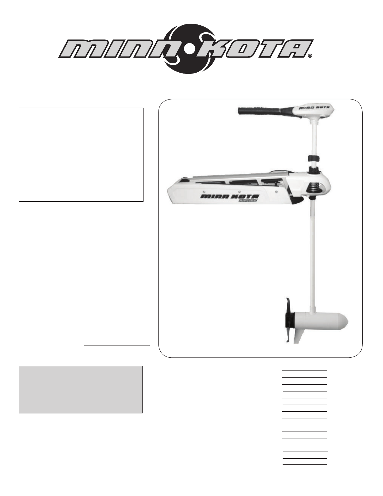
Master User Manual for RIPTIDE SF
BOW MOUNT
HAND CONTROL
SALTWATER
MOTORS
Features
Assembly
Installation
Operation
Gas Assist
Cautions
Circuit Breaker
Battery Information
Battery Connection
Wiring Diagram
Propeller Replacement
Maximizer
Maintenance
Troubleshooting
Warranty
pg. 2
pg. 3
pg. 4-5
pg. 6-7
pg. 8
pg. 9
pg. 9
pg. 10
pg. 10
pg. 11
pg. 12
pg. 12
pg. 13
pg. 13
pg. 14
note: do not return your minn kota motor to your
retailer. your retailer is not authorized to repair
or replace this unit. you may obtain service by:
•
calling minn kota at: 1-800-227-6433 or
1-507-345-4623;
• returning your motor to the minn kota factory
service center;
•
sending or taking your motor to any minn kota
authorized service center on enclosed list.
please include proof of purchase, serial number
and purchase date for warranty service with any
of the above options.
PLEASE THOROUGHLY READ THIS USER MANUAL. FOLLOW ALL INSTRUCTIONS AND HEED ALL
SAFETY & CAUTIONARY NOTICES BELOW. USE OF
THIS MOTOR IS ONLY PERMITTED FOR PERSONS
THAT HAVE READ AND UNDERSTOOD THESE USER
INSTRUCTIONS. MINORS MAY USE THIS MOTOR ONLY
UNDER ADULT SUPERVISION.
Page 2
FEATURES
2
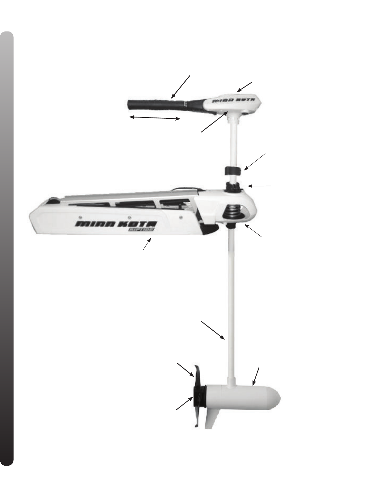
RIPTIDE OVERVIEW
Advanced Saltwater
Corrosion Protection:
3-mil acrylic paint
E-coated epoxy
Chromate conversion coat
7-step cleaning process
Premium marine alloy
6”
Maximizer / Permanently Sealed
Electronics
(On select models)
Tilt Twist Tiller Extension & 6” Handle
Battery Meter
Adjustable Depth Collar
Steering Tension Knob
BowGuard 360°®
Breakaway Protection as
shown or with Hinge and door
Mounting Bracket
Lifetime Warranty Flexible Composite Shaft
Weedless Wedge Propeller
Replaceable Sacrificial
Anode Extends
Protection Against
Galvanic Corrosion
Specifications subject to change without notice.
Permanent Magnet Motor
Page 3
ASSEMBLY OF MOTOR TO MOUNT:
1. Place the mount on an elevated surface such as a workbench or tailgate of pickup.
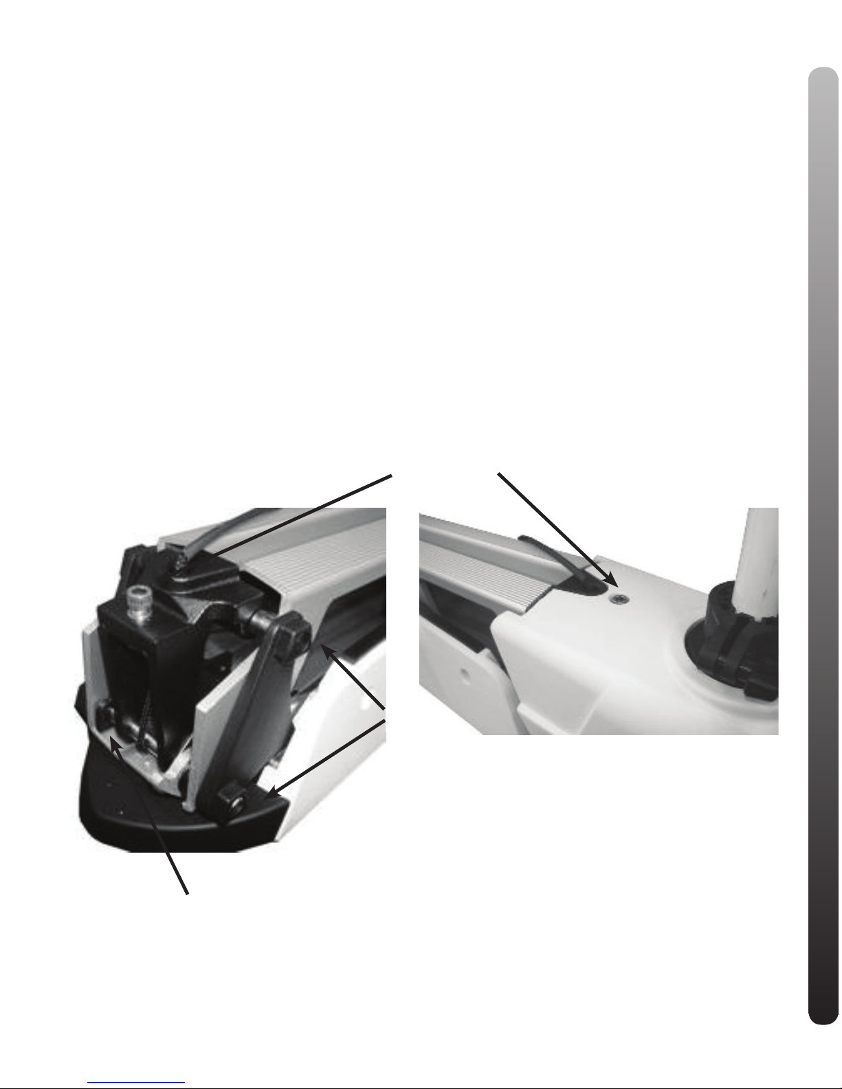
2. Remove the 5/16” Allen screw and lock washer from the
mount using a ⁄” Allen wrench. (See picture)
3. Align the key ways on the inside of the bowguard with
the ends links on the mount. Lower the motor assembly
straight down until seated.
4. Install the 5/16” Allen screw / lock washer and tighten to
10-12 ft/lbs.
5. Stow the motor into the flat position by pulling the rope/
handle to disengage the latch bar, allowing the motor to
fold into the flat position.
6. Once in the stowed or flat position, the gas spring pin
can be installed. Follow the steps below to install the
gas spring pin:
• Locate the upper gas spring pin in bag assembly
• Align the end of the gas spring with the holes in the
outer arm
• Install pin and Phillips flat head screws
• Tighten screws until the heads are flush with the
outer arm
NOTE: Screws have a pre-applied thread locker, DO
NOT apply additional thread locker to screws as that
may prevent future removal.
7. Motor / mount can now be installed onto the boat.
Proceed to next page for mounting instructions.
ATTENTION: The 5/16” Allen screw must be tight
when installed and periodically tightened to 10-12 ft/lbs
(Step 4), which will allow the motor to be stowed properly. Tighten the Allen screw when the mount is in the
deployed position.
ASSEMBLY
3
Allen Screw
Safety Latch
keys
Page 4
INSTALLATION
4
INSTALLATION OF THE BOWMOUNT:
We recommend that you have another person help with this
procedure.
1. For installation, do not remove the shaft/motor from the
Bowguard. The Bowguard spring is under tension and must
always remain secured.
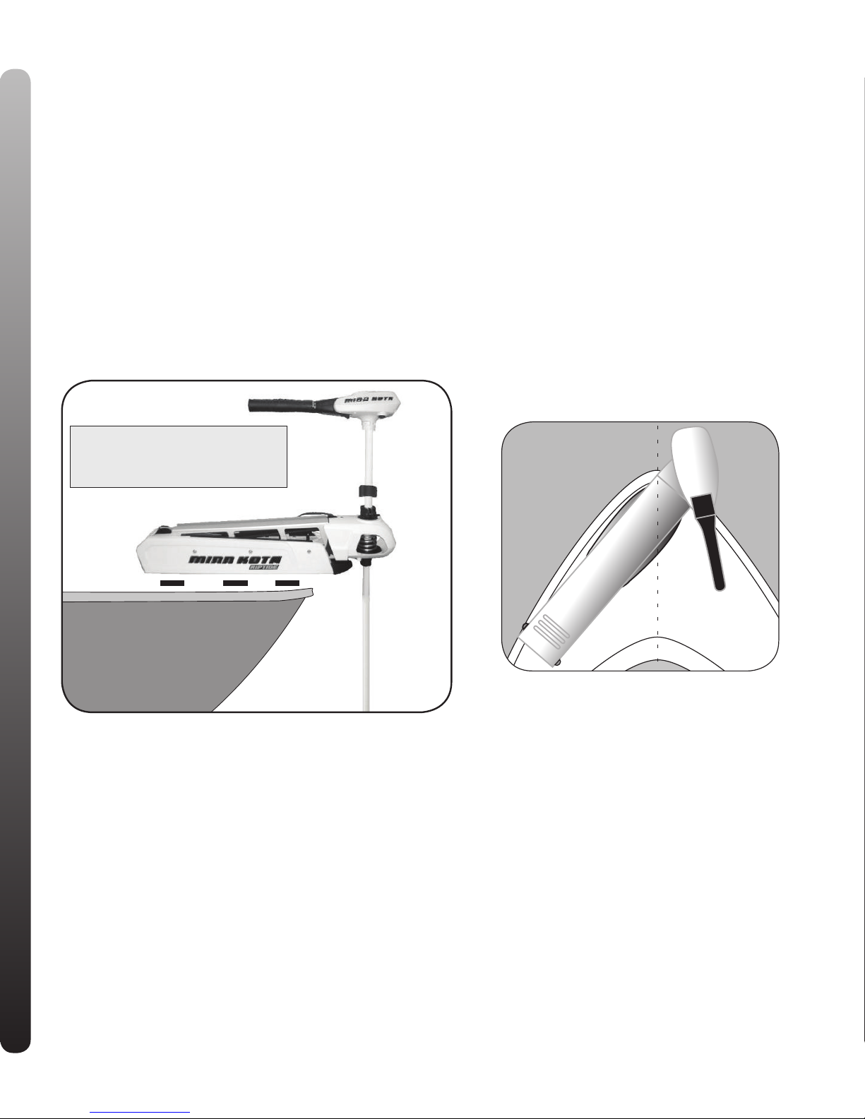
2. Place the mount, with the motor in the fully retracted (flat)
position, on the deck of the boat:
• The motor should be mounted as close to the centerline
of the boat as possible.
• Make sure bow area under the chosen location is clear
and unobstructed for drilling.
• Make sure the motor rest is positioned far enough
beyond the edge of the boat. The motor, as it is lowered
into the water or raised into the boat, must not encounter
any obstructions.
3. Once in position, mark at least four (4) of the holes provided in the bow plate and drill through the marks using a
(9/32”) bit.
4. Mount the plate to the bow through the drilled holes using
the provided (1/4-20 x 3-1/2”) bolts, nuts and washers.
NOTE: If possible, secure all sets of mounting bolts, nuts
and washers.
CAUTION: MAKE SURE YOUR
MOTOR IS MOUNTED ON A
LEVEL SURFACE
Page 5
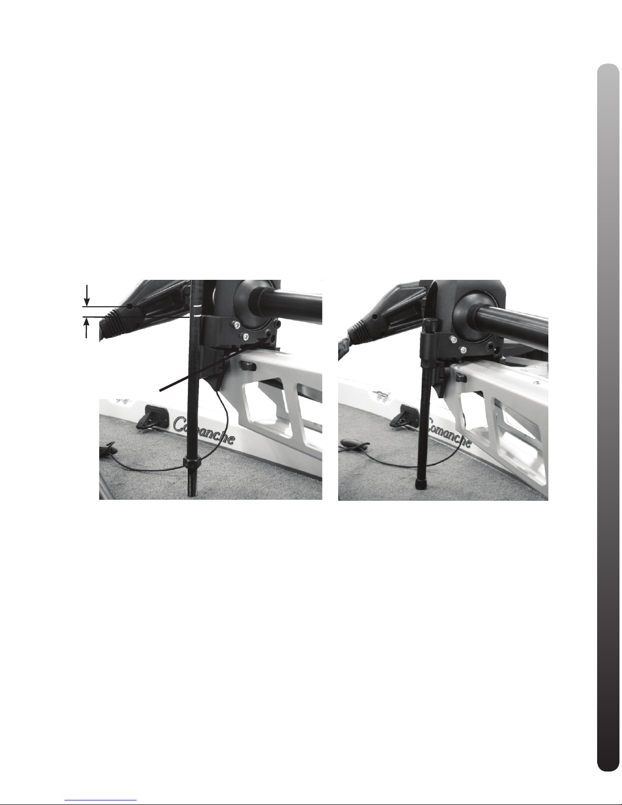
INSTALLING THE BOWMOUNT STABILIZER: (if Included)
1. Place motor in the stowed position
2. Unthread the composite rod from the bracket and attach bracket to the bottom of the bowguard using the 5/16” cap
screws and nuts. The nuts fit into pocket on the inside of the bowguard behind the spring.
NOTE: The bracket can be installed on the left or right side of the bowguard.
3. Pull the bumper off the stabilizer rod and place the rod next to the bracket as shown in photo.
4. Place the threaded end down onto the deck surface and mark the rod fl” above the top of the bracket (see photo)
5. Cut the rod to the mark and round the cut edge with a file or sandpaper.
6. Install the bottom bumper to the stabilizer rod and thread the rod into the bracket.
7. Adjust the stabilizer rod up or down to so that the tip just touches the support surface. See photo below.
WARNING: Adjusting the rod too tightly removes the end play needed for proper pin engagement and doing so
could prevent the mount from fully latching in the stowed position. If installed correctly, the rod tip should
lift off the deck about 1/4” without the mount unlatching.
8. Once adjusted, tighten the jam nut against the bracket, which will prevent the rod from turning.
9. Install top cap if threads are exposed.
3/4”
Optional mounting holes
INSTALLATION
5
Page 6
WARNING : WHEN RAISING OR LOWERING MOTOR, KEEP FINGERS CLEAR OF ALL HINGE AND PIVOT
POINTS AND ALL MOVING PARTS.
BOW MOUNT OPERATION:
• The bow mount is designed to fold back and lock the
motor flat on deck when not in use.
• The motor rest positions the lower unit as it comes in
contact with the nose of the mount and guides it onto the
motor rest.
• The tube lock tilts up and engages the shaft to lock it for
transport.
• The hold down strap assembly crosses over the shaft
and the retangular ring / Velcro® secures the motor.
• Pull the rope to release the lock bar, which automatically
engages when the unit is lowered or raised into position.
The pull grip and rope should be used to both lower and
raise the unit.
• If the rope disengages from the lock bar assembly,
release the lock bar with a screwdriver.
TILT AND EXTENSION HANDLE
OPERATION:
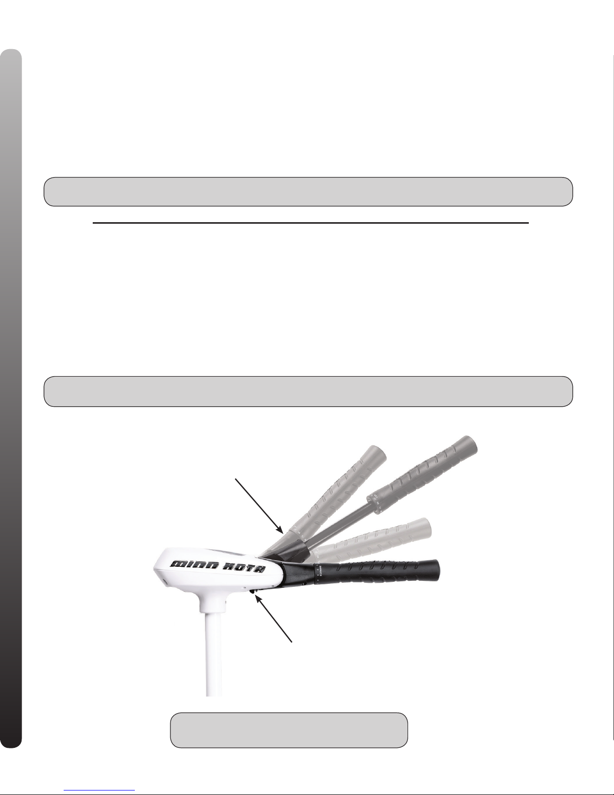
Your MAXXUM trolling motor features 7 usable handle
tilt positions…45°, 30°, and 15° up and down from the
0° (horizontal) position. To use the down positions, you
must first press the release button located on the left
underside of the pivot handle.
Your MAXXUM trolling motor handle also features
a unique stow position, that is useful for limiting the
amount of space required for storage or travel.
First press the release button located on the left under-
side of the pivot handle, then push the handle down until
you feel the handle “lock in” to the stowed position. This
will be almost parallel to the motor shaft.
To extend the handle, pull the handle towards you to the
desired position. The handle will extend a full 6 inches.
To retract, push the handle in until it meets the face of
the motor control head.
IMPORTANT: THE MOTOR MUST BE IN THE OFF POSITION TO USE THE STOW POSITION! FAILURE TO PUT
THE MOTOR IN THE OFF POSITION BEFORE STOWING THE HANDLE WILL RESULT IN JOINT FAILURE.
CAUTION: NEVER OPERATE YOUR MOTOR
WHEN IT IS OUT OF THE WATER.
Handle controls on/off,
steering, forward/reverse
Release button
OPERATION
6
Page 7
OPERATION
7
OPERATION OF THE PRODUCT CONT’D:
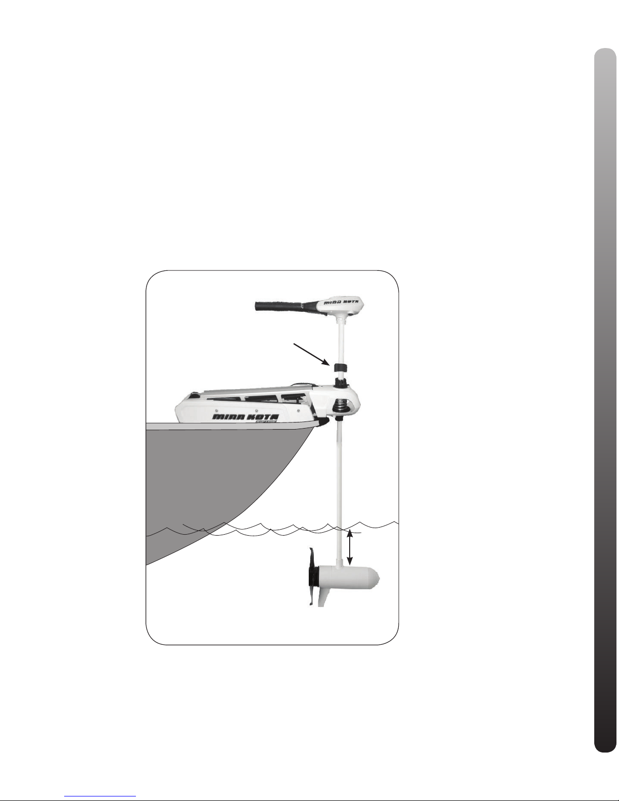
Depth Adjustment
• Firmly grasp the outer shaft or control head and hold it
steady.
• Loosen depth setting knob on the hinge cover until the
shaft slides freely.
• Raise or lower the motor to the desired depth.
• Turn the motor control head to the desired position.
• Tighten depth setting knob to secure the motor in
place.
NOTE: When setting the depth be sure the top of the
motor is submerged at least 12” to avoid churning or
agitation of surface water. The propeller must be completely submerged.
STEERING ADJUSTMENT:
• Adjust steering tension knob to provide enough tension
to allow the motor to turn freely, yet remain in any position without being held or; Tighten the knob and lock the
motor in a preset position to leave your hands free for
fishing.
12” Minimum depth
Depth Collar
Knob
Page 8
GAS ASSIST LIFT MECHANISM:
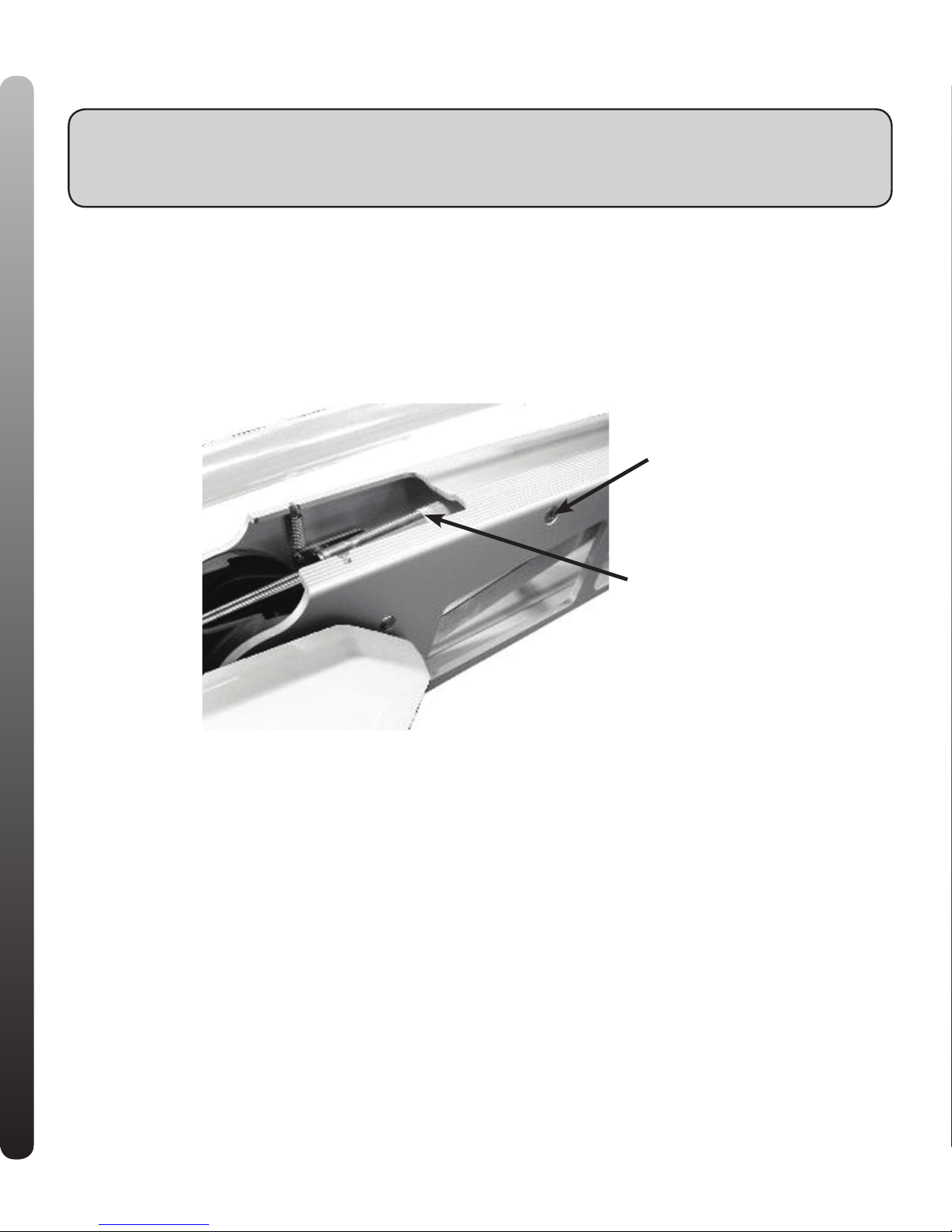
To disconnect one end of the gas spring, follow the instructions below:
1. With the mount in the stowed position, locate the upper cylinder pin.
2. Using two Philips screwdrivers, remove 1 of the Phillips flat head screws.
3. Remove pin from outer arm by sliding thru the arm.
4. Now it is safe to deploy the motor and remove the motor assembly.
5. To re-connect the gas spring, see page 3, step 6.
WARNING: The gas assist lift mechanism in this unit is under HIGH SPRING PRESSURE when the
motor is in the deployed position. DO NOT remove the BowGuard assembly from the mount without disconnecting one end of the gas spring. Failure to do this can create a condition where accidental pulling of the
rope may cause the mount to spring open rapidly, striking anyone or anything in the direct path.
Philips Screw
Gas Spring Bracket
GASS ASSIST LIFT MECHANISM
8
Page 9

CAUTIONS CIRCUIT BREAKER
9
Attention:
•Avoid running your motor with the propeller outside of the water. This may result in injuries from the rotating
propeller.
•It is recommended to set the speed selector to zero and place the motor in the deployed position prior to connecting power cables. Disconnect power cables prior to stowing.
•Always ensure that the power cables are not twisted or kinked; and that they are securely routed to avoid a
safety or trip hazard. Ensure cables are unobstructed in all locations to avoid damaging the wire insulation.
Damage to the insulation could result in failure or injury.
•Always inspect the insulation of the power cables prior to use to ensure they are not damaged.
•Disregarding these safety precautions may result in an electrical short of the battery(s) and/or motor. Always
disconnect the motor from the battery(s) before cleaning or checking the propeller.
•Avoid submerging the complete motor as water may enter the lower unit through control head and shaft.
Water in the lower unit may cause an electrical short and damage the lower unit. This damage will not be
covered by warranty.
Caution!
•Always operate the motor in a safe distance away from obstructions. Never approach the motor when the
propeller is running. Contact with a spinning propeller may endanger you or others.
•Always exercise safe practices when using your motor; stay clear of other watercrafts, swimmers, and any
floating objects. Always obey water regulations applicable to your area of operation.
•Never operate the motor while under the influence of alcohol, drugs, medication, or other substances which
may impair your ability to safely operate equipment.
•This motor is not suitable for use in strong currents exceeding the thrust level of the motor.
The constant noise pressure level of the motor during use is less than 70dB(A). The overall vibration level does
not exceed 2,5m/sec≈.
Boat Rigging and Motor Installation:
An over-current protection device (circuit breaker or fuse) must be used with this motor. Coast Guard requirements
dictate that each ungrounded current-carrying conductor must be protected by a manually reset, trip-free circuit breaker or
fuse. The type (voltage and current rating) of the fuse or circuit breaker must be sized accordingly to the trolling motor used.
The following breaker sizes are recommended guidelines:
Maximum thrust Voltage / Recommended circuit breaker rating
30# to 45# 12V 50A @ 12VDC
50# to 55# 12V 60A @ 12VDC
65# to 70# 24V 50A @ 24VDC
80# 24V 60A @ 24VDC
101# 36V 50A @ 36VDC
E-Drive 48V 40A @ 48VDC
The appropriate wire size needed to connect your trolling motor to the trolling motor batteries varies depending on the length
of cable needed and voltage of the motor. For additional information, please consult appropriate ABYC (American Boat and
Yacht Council) and Coast Guard requirements.
Reference:
United States Code of Federal Regulations: 33 CFR 183 – Boats and Associated Equipment
ABYC E-11: AC and DC Electrical Systems on Boats
Page 10
BATTERY INFORMATION BATTERY CONNECTION
10
BATTERY INFORMATION:
The motor will operate with any deep cycle marine 12 volt
battery/batteries. For best results use a deep cycle,
marine battery with at least a 115 ampere hour rating.
As a general on the water estimate, your 12 volt motor
will draw one ampere per hour and your 24 volt motor
will draw .75 ampere per hour for each pound of thrust
produced when the motor is running on high. The actual
ampere draw is subject to your particular environmental
conditions and operation requirements. Maintain battery
at full charge. Proper care will ensure having battery
power when you need it, and will significantly improve
the battery life. Failure to recharge lead-acid batteries
(within 12-24 hours) is the leading cause of premature
battery failure. Use a variable rate charger to avoid
overcharging.
If you are using a crank battery to start a gasoline out-
board, we recommend that you use a separate deep
cycle marine battery/batteries for your Minn Kota trolling
motor.
Advice regarding batteries:
Never connect the (+) and the (–) terminals of the bat-
tery together. Take care that no metal object can fall
onto the battery and short the terminals. This would
immediately lead to a short and utmost fire danger.
Recommendation: Use battery boxes and covered battery
terminal clamps like Minn Kota accessory #MK-BC-1.
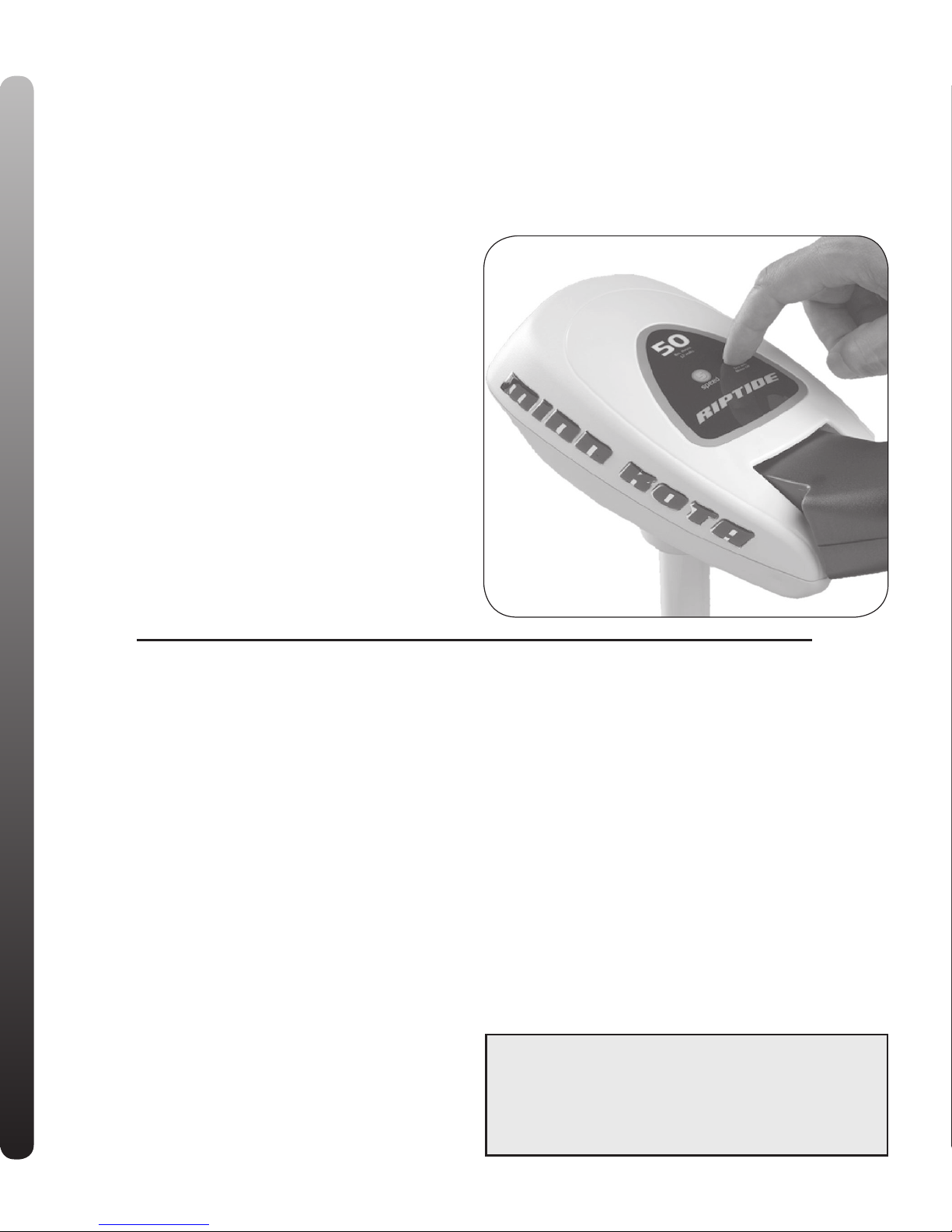
These motors are equipped with a “push to test” battery
gauge. The LED provides an accurate display of the
remaining charge in the battery. It is only accurate when
the motor is off. The gauge reads as:
• Four lights indicate full charge.
• Three lights indicate good charge.
• Two lights indicate low charge.
• One light indicates recharge.
BATTERY CONNECTION
12 Volt Systems:
1. Make sure that the motor is switched off (speed selector on “0”).
2. Connect positive (+) red lead to positive (+) battery terminal.
3. Connect negative (–) black lead to negative (–) battery terminal.
4. For safety reasons do not switch the motor on until the propeller
is in the water.
24 Volt Systems:
1. Make sure that the motor is switched off (speed selector on “0”).
2. Two 12 volt batteries are required.
3. The batteries must be wired in series, only as directed in wiring
diagram, to provide 24 volts.
a. Connect a connector cable to positive (+) terminal of battery 1
and to negative (–) terminal of battery 2.
b.Connect positive (+) red lead to positive (+) terminal on battery
2.
c. Connect negative (–) black lead to negative (–) terminal of bat-
tery 1.
4. For safety reasons do not switch the motor on until the propeller
is in the water.
36 Volt Systems:
1. Make sure that the motor is switched off (speed selector on “0”).
2. Three 12 volt batteries are required.
3. The batteries must be wired in series, only as directed in wiring
diagram, to provide 36 volts.
a. Connect a connector cable to positive (+) terminal of battery 1
and to negative (–) terminal of battery 2.
b. Connect a connector cable to positive (+) terminal of battery 2
and to negative (–) terminal of battery 3.
c. Connect positive (+) red lead to positive (+) terminal on bat-
tery 3.
d. Connect negative (–) black lead to negative (–) terminal of bat-
tery 1.
4. For safety reasons do not switch the motor on until the propeller
is in the water.
If installing a leadwire plug, observe proper polarity and fol-
low instructions in your boat owner’s manual.
See wiring diagram on following pages.
• IMPROPER WIRING OF 24 OR 36 VOLT SYSTEM COULD
CAUSE BATTERY EXPLOSION!
• KEEP LEADWIRE WING NUT CONNECTION TIGHT AND
SOLID TO BATTERY TERMINALS.
• LOCATE BATTERY IN A VENTILATED COMPARTMENT.
Page 11
12v
24v
36v
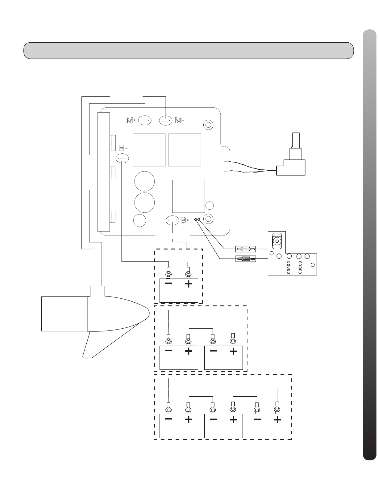
12-24-36 VOLT VARIABLE SPEED MODELS
RED/ROUGE M+
BLACK/NOIR M -
CONTROL BOARD/
CARTE DE COMMANDE
RED/ROUGE
BLACK/NOIR
BATTERY GAUGE/
VOLTMéTRE
12V BATT 1
BLACK/NOIR B-
RED/ROUGE B+
MOTOR/
MOTEUR
SPEED ADJUSTMENT KNOB
MOLETTE DE REGLAGE DE LA VITESSE
12V BATT 1
12V BATT 1
12V BATT 2
12V BATT 3
12V BATT 2
THIS IS A UNIVERSAL MULTI-VOLTAGE DIAGRAM. DOUBLE CHECK YOUR MOTORS VOLTAGE FOR PROPER CONNECTIONS
WIRING DIAGRAM
11
Over-Current Protection Devices not shown in illustrations.
Page 12
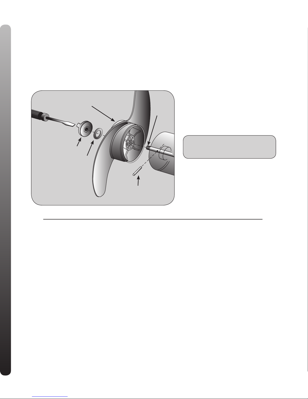
PROPELLER REPLACEMENT:
• Disconnect motor from battery prior to changing the propeller.
• Hold the propeller and loosen the prop nut with a pliers
or a wrench.
• Remove prop nut and washer. If the drive pin is sheared/
broken, you will need to hold the shaft steady with a
screwdriver blade pressed into the slot on the end of the
shaft.
• Turn the old prop to horizontal ( as illustrated ) and pull it
straight off. If drive pin falls out, push it back in.
• Align new propeller with drive pin.
• Install prop washer and prop nut.
• Tighten prop nut 1/4 turn past snug. [25-35 inch lbs.] Be
careful, over tightening can damage prop.
CAUTION: DISCONNECT THE MOTOR
FROM THE BATTERY BEFORE BEGINNING
ANY PROP WORK OR MAINTENANCE.
PROPELLER MAXIMIZER
12
DRIVE PIN
SLOT
WEEDLESS PROPELLER
PROP WASHER
ANODE/NUT
MAXIMIZER™:
The built-in Maximizer’s electronics create
pulse width modulation to provide longer running time and extended battery life. With the
Maximizer speed control, you may, in some
applications, experience interference in your
depth finder display. We recommend that you
use a separate deep cycle marine battery for
your trolling motor and that you power the
depth finder from the starting / cranking battery. If problems still persist, call our service
department at 1-800-227-6433.
Page 13

MAINTENANCE OF THE PRODUCT:
1. After use, these units should be rinsed with fresh water,
then wiped down with a cloth dampened with an aqueous based silicone spray such as Armor All®.
2. The propeller must be cleaned of weeds and fishing line.
The line can get behind the prop, wear away the seals
and allow water to enter the motor. Check this after
every 20 hours of operation.
3. Before each use, check to see that the prop nut is
secure.
4. To prevent accidental damage during trailering or storage, disconnect the battery whenever the motor is off of
the water. For prolonged storage, lightly coat all metal
parts with an aqueous based silicone spray.
5. For maximum performance, restore battery to full charge
before each use.
6. Keep battery terminals clean with fine sandpaper or
emery cloth.
7. The weedless wedge propeller is designed to provide
absolute weed free operation with very high efficiency.
To maintain this top performance, the leading edge of
the blades must be kept smooth. If they are rough or
nicked from use, restore to smooth by sanding with fine
sandpaper.
8. Grease latch pins periodically to prevent binding or sticking.
9. The 5/16” Allen scew that attaches the motor to the
mount should be periodically tightened to 10-12 ft lbs
to prevent motor stowing problems. Tighten the Allen
screw when the mount is in the deployed position.
TROUBLESHOOTING:
1. Motor fails to run or lacks power:
• Check battery connections for proper polarity.
• Make sure terminals are clean and corrosion free. Use fine
sandpaper or emery cloth to clean terminals.
• Check battery water level. Add water if needed.
2. Motor loses power after a short running time:
• Check battery charge, if low, restore to full charge.
3. Motor is difficult to steer:
• Check steering cables for proper tension. Adjust as necessary.
4. You experience prop vibration during normal operation:
• Remove and rotate the prop 180°. See removal instructions
in prop section.
5. Unit difficult to deploy:
• Gas spring relaxes after prolong periods of sitting. Stow and
deploy motor a few times until latch pins latch freely.
6. Motor drains battery when not in use.
Switch MOM/OFF/CON switch on foot pedal to OFF position
when not in use. Motor will drain battery in either MOM or
CON positions.
7. Lift-assist not functioning:
• Ensure lift-assist pin was installed prior to motor use.
8. Motor shaft falls to one side of the motor shaft yoke when
stowing.
• The 5/16” Allen screw that attaches the motor to the mount
should be periodically tightened to 10-12 ft/lbs. Tighten the
Allen screw when the mount is in the deployed position.
NOTE: For all other malfunctions, see enclosed Authorized
Service Center (ASC) listing for nearest ASC.
MAINTENANCE
TROUBLESHOOTING
13
Page 14
PARTS LIST
REPAIR AND TROUBLESHOOTING
We off er several options to help you troubleshoot and/or repair your product. Please read through the options listed below.
FREQUENTLY ASKED QUESTIONS
Did you know that we have over 100 FAQ’s to help answer all of your Minn Kota questions? Visit www.minnkotamotors.com
and click on “Frequently Asked Questions” under the “Service” tab to fi nd an answer to your question.
http://www.minnkotamotors.com/service/faq.aspx?linkidentifi er=id&itemid=817
AUTHORIZED SERVICE CENTERS
Minn Kota has over 300 authorized service centers in the United States and Canada where you can purchase parts or get your
products repaired. Please visit www.minnkotamotors.com and click on “Service Center Locator” under the “Service” tab to
locate a service center in your area.
http://www.minnkotamotors.com/service/asclocator.aspx
CALL US (FOR U.S. AND CANADA)
Our customer service representatives are available Monday – Friday between 7:00am – 4:30pm T at 800-227-6433. If you
are calling to order parts, please have the 11-character serial number from your product, specifi c part numbers, and credit card
information available. This will help expedite your call and allow us to provide you with the best customer service possible. You
can reference the parts list located in your manual to identify the specifi c part numbers.
EMAIL US
You can email our customer service department with questions regarding your Minn Kota products. To email your quesiton, visit
www.minnkotamotors.com and click on “Contact Us” under the “Service” tab.
http://www.minnkotamotors.com/service/contact.aspx
Page 15
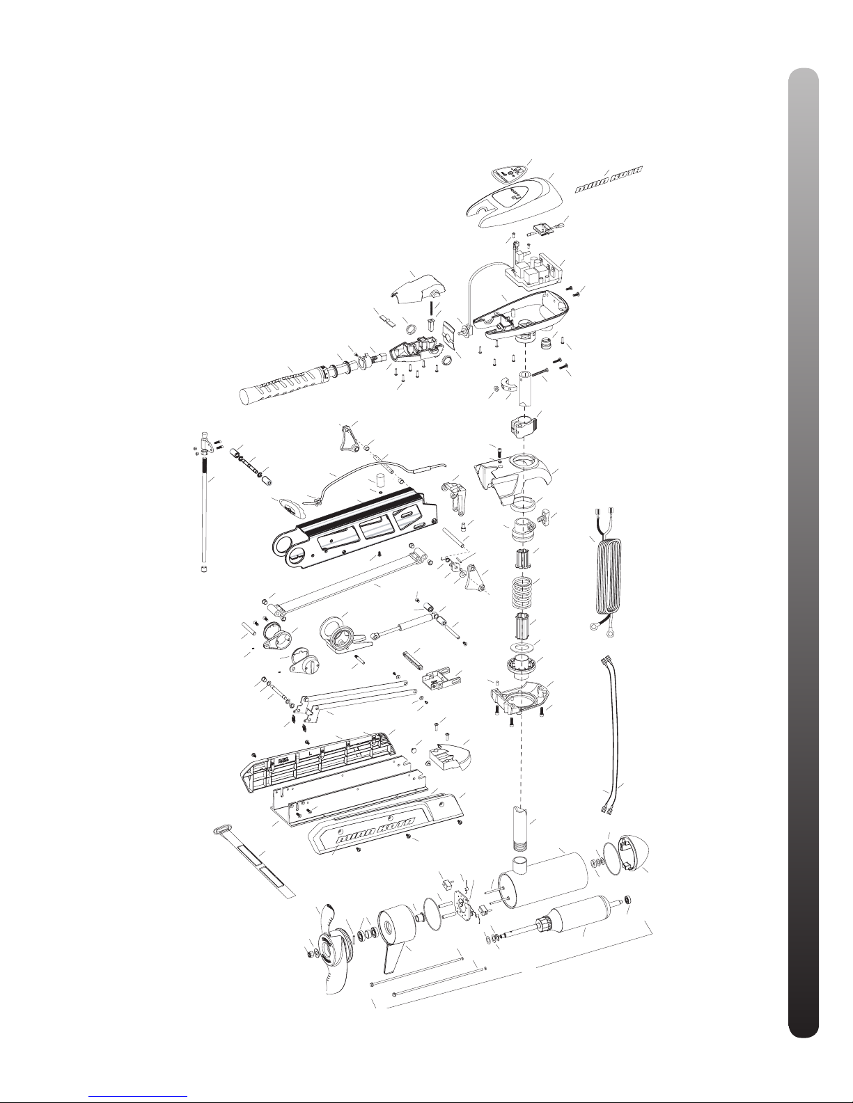
425
260
255
220
225
235
215
230
420
240
200
205
210
400
395
265
410
390
360
365
370
375
380
385
250
245
415
405
208
700
720
721
980
710
815
725
730
735
740
745
750
760
765
810
830
835
820
825
845
860
865
870
875
880
940
975
885
890
910
920
915
925
935
930
932
905
900
895
770
775
780
785
790
795
800
850
855
515
520
525
535
530
540
550
555
560
570
500
510
565
136
310
135
5
10
85
15
100
35
40
80
90
1000
1010
1015
1020
50
110
120
115
60
65
1
70
20
95
30
25
715
737
545
796
752
751
753
710
871
776
PARTS LIST
This page provides MinnKota® WEEE compliance disassembly instructions. For more information about
where you should dispose of your waste equipment for recycling and recovery and/or your European Union
member state requirements, please contact your dealer or distributor from which your product was purchased.
Tools required: Flat head screw driver, Phillips screw driver, Socket set, Pliers, Wire cutters.
RT80/SF 24 Volt and
RT101/SF 36 Volt
52” or 62” SHAFT
Page 16

In the U.S.A., replacement parts may be ordered directly from MINN KOTA Parts Dept., 121 Power Drive,P.O. Box 8129 Mankato, Minnesota 56002-8129. In Canada,
parts may be ordered from any of the Canadian Authorized Service Centers shown on the enclosed list. Be sure to provide the model and serial numbers of your motor
when ordering parts. Please use the correct part numbers from the parts list. Payment for any parts ordered from the MINN KOTA parts department, may be by cash,
personal check, Discover Card, MasterCard or VISA. To order, call 1-800-227-6433 or FAX 1-800-527-4464.
* This item is part of an assembly. This item cannot be sold separately due to machining and /or assembly that is required.
PARTS LIST
Item P/N Description Qty Item P/N Description Qty
80# Motor
1 2316226 24V Motor 62” SW 1
5 2-100-214 Armature assembly 1
10 140-010 Bearing 1
15 788-040 Retaining ring 1
20 2-200-397 Center housing assemby 1
25 2-300-340 Brush end housing assembly 1
30 421-376 Plain end housing assembly STD 1
35 144-017 Flange bearing 1
40 880-025 Seal 2
50 188-094 Brush 2
60 9-738-004 Brush plate assembly 1
65 975-041 Brush spring 2
70 701-043 O-ring, motor 2
80 701-009 O-ring, thru-bolt 2
85 830-027 Screw, 10-32 x 2 2
90 830-094 Thru-bolt 2
95 990-051 Washer, steel 2
100 990-052 Washer, nylatron 2
110 973-025 Spacer, brush plate 2
115 992-010 Washer, Belleville 2
120 990-045 Spacer, thrust 1
135 640-021 Leadwire, black 1
136 640-126 Leadwire, red 1
n 2889460 Seal and O-ring Kit
101# Motor
1 2316286 36V Motor 62” SW 1
5 2-100-216 Armature assembly 1
10 140-010 Bearing 1
15 788-040 Retaining ring 1
20 2-200-310 Center housing assemby 1
25 2-300-340 Brush end housing assembly 1
30 421-376 Plain end housing assembly STD 1
35 144-017 Flange bearing 1
40 880-025 Seal 2
50 188-094 Brush 2
60 9-738-004 Brush plate assembly 1
65 975-041 Brush spring 2
70 701-043 O-ring, motor 2
80 701-009 O-ring, thru-bolt 2
85 830-027 Screw, 10-32 x 2 2
90 830-096 Thru-bolt 2
95 990-051 Washer, steel 2
100 990-052 Washer, nylatron 2
110 973-025 Spacer, brush plate 2
115 992-010 Washer, Belleville 2
120 990-045 Spacer, thrust 1
135 640-021 Leadwire, black 1
136 640-126 Leadwire, red 1
n 2889460 Seal and O-ring Kit
200 2195659 Decal, c-box cover 80# 1
2095604 Decal, c-box cover 101# 1
205 2060296 C-box cover 1
208 2325666 Decal - MinnKota 2
210 2074081 Battery meter, 24v SW 1
2074082 Battery meter, 36v SW 1
215 3043427 Screw, #8 x 7/8 SS 2
220 2184017 Control board, 24/36V 1
n 2888411 Potentiometer Replacement Kit
225 2303434 Screw, #8-30 x 5/8 SS 2
230 2062503 Control box, VARS, SW 1
235 2062905 Strain relief 1
240 2303412 Screw, #6 x 5/8 SS 6
245 2263434 Screw, #8 x 1 SS 2
250 2383406 Screw, #10-24 x 2 SS 1
255 2061517 Collar, c-box 1
260 2383101 Nut, 10-24, nylock, SS 1
265 2991521 Cam lock/depth collar assy 1
310 2002014 Tube Composite 52” 1
2002015 Tube Composite 62” 1
n 2990957 Handle assy, VARS [360-410] 1
360 2990456 Grip/handle assy, VARS [360-375] 1
365 2060015 Bearing, handle 2
370 2063405 Screw, #6 PFH SS 1
375 2884092 Yoke / spider assy, VARS 1
380 2302742 Spring, detent, off 1
385 2060005 Bearing, handle pivot 2
390 2060900 Handle pivot, top 1
395 2302745 Spring, release button 1
400 2063700 Button, release 1
405 2060905 Handle pivot, bottom 1
410 2303412 Screw, #6 x 5/8 SS 6
415 2062715 Spring, handle pivot 1
420 2061700 Washer, pot holder 1
425 2992521 Leadwire assy 1
n 2991757 Bowguard Assembly SW [500-570] 1
500 2263422 Screw, 5/16 x 1 SHCS 1
510 2281700 Washer, 5/16 highcollar lock 1
515 2281943 Bowguard top 1
520 2280001 Bearing, Bowguard top 1
525 2011366 Knob, ss 1
530 2261525 Spring sleeve, upper 1
535 2264702 Tube insert, upper 1
540 2262705 Spring, bowguard 1
545 2282000 Tube insert, lower 1
550 2281525 Spacer, lower spring 1
555 2281520 Spring sleeve, lower 1
Page 17

Fuera de los Estados Unidos, consultar la lista anexa para ubicar el Centro de servicio autorizado MINN KOTA. No dejar de incluir el número del MODELO
y el número de SERIE del motor para el cual se solicitan las piezas. Usar siempre los números de pieza correctos indicados en la lista de piezas.
PARTS LIST
560 2991726 Bowguard bottom 1
565 2262632 Spring pin 1/4 x 5/8, ss 2
570 2263422 Screw, 5/16 x 1, ss 3
n 2991749 Mount, Fortrex, Short 52” [700-940] 1
n 2991750 Mt, Fortrex, Long 80# 62” [700-940] 1
n 2991751 Mt, Fortrex, Long 101# 62” [700-940] 1
700 2280800 Link, bowguard mount, left 1
710 2287303 Bushing, upper pins 2
715 2283409 Screw, 1/4-20 x 3/4 FHSC 4
720 2880400 Pull grip assembly 1
721 2261732 Washer 2
725 2771601 Rope assembly 1
730 2281516 Spacer, inner arm 1
735 2281702 Washer, lock 1/4 1
737 2284202 Outer arm, short, 52” 1
2284212 Outer arm, long, 62” 1
740 2992322 Rope guide assembly 1
745 2281530 Insert, threaded 1
750 2282608 Pin, 7/16 x 5 5/32 1
751 2282602 Pin, 3/8 x 3 3/4 1
752 2261505 Spacer 2
753 2263011 E-ring, 3/8 shaft 2
760 2223418 Screw, 1/4-20 x 1/2 BHCS 1
765 2993819 Inner arm assembly, short, 52” 1
2993821 Inner arm assembly, long, 62” 1
770 2042711 Spring, torsion 1
775 2283620 Latch, safety 1
776 2282611 Spring, safety latch 1
780 2281704 Washer 7/16 nylon 1
785 2280805 Link, bowguard mount, right 1
790 2283410 Screw 1/4-20 x 1/2 PFH 2
795 2288403 Gas spring (cylinder), 80/101#, short 1
2288404 Gas spring (cylinder), 80#, long mt 1
2288405 Gas spring (cylinder), 101#, long mt 1
796 2281710 Spacer, gas spring 2
800 2282610 Pin, upper, shock 1
810 2280005 Bearing, nyliner 7/16” 4
815 2282600 Pin, 7/16 x 4 7/8 1
820 2281932 Bracket, rear pivot 2
825 2281501 Yoke, shock mount 1
830 2282606 Pin, 7/16 x 4 1/2 1
835 2283402 Screw, set, 6-32 x 1/4 2
845 2282604 Pin, Knurled 5/16 x 2 1
850 2283615 Latch bar 1
855 2283610 Bracket - latch/strap, rope pull 1
860 2287300 Bushing, rear pivot 2
865 2282602 Pin, 3/8 x 3 3/4 1
870 2263011 E-ring, 3/8 shaft 2
871 2280008 Bearing, Iglide 2
875 2282720 Spring, extension 2
880 2773600 Latch strap assembly, short 1
2773601 Latch strap assembly, Long 1
885 2261732 Washer 8, nylon 2
890 2373450 Screw 8-18 x 3/8 2
n 2993911 Sideplate assembly, short, left, sw 1
n 2993916 Sideplate assembly, long, left, sw 1
895 2288625 Support, left sideplate 1
900 2283408 Screw 8 x 3/8 8
905 2283911 Sideplate, short, left, sw 1
2283916 Sideplate, long, left, sw 1
910 2073408 Screw 1/4-20 x 7/8 2
915 2286700 Plug, spacer 2
920 2283900 Ramp, motor 1
n 2993921 Sideplate assembly, short, right, sw 1
2993926 Sideplate assembly, long, right, sw 1
925 2288620 Support, right sideplate 1
930 2283921 Sideplate, short, right, sw 1
2283926 Sideplate, long, right, sw 1
932 2285501 Decal, Sideplate, sw 2
935 2281902 Base extrusion, short, 52” 1
Base extrusion, long, 62” 1
940 2323405 Screw 1/4-20 x 1/2 6
975 2773806 Strap hold down 1
980 2991925 Bracket stabilizer assembly 1
n 1378132 Propeller kit WW2
n 2994876 Propeller bag assy
1000 2331160 Propeller WW2 1
1010 2262658 Drive pin, large 1
1015 2091701 Washer, prop, large 1
1020 2198401 Nut, nylock, prop, Anode 1
n 2994830 Bag assembly 1
Item P/N Description Qty Item P/N Description Qty
p/n 2284905 REV. Z 34323 07/14
Page 18

Composite Shaft
Johnson Outdoors Marine Electronics, Inc. warrants to the
original purchaser that the composite shaft of the purchaser’s Minn Kota® trolling motor is free from defects in materials and workmanship appearing within the original purchaser’s lifetime. Johnson Outdoors Marine Electronics,
Inc. will provide a new shaft, free of charge, to replace any
composite shaft found to be defective more than two (2)
years after the date of purchase. Providing such a new
shaft shall be the sole and exclusive liability of Johnson
Outdoors Marine Electronics, Inc. and the sole and exclusive remedy of the purchaser for breach of this warranty;
and purchaser shall be responsible for installing, or for the
cost of labor to install, any new composite shaft provided
by Johnson Outdoors Inc.
Entire Product
Johnson Outdoors Marine Electronics, Inc. warrants to the
original purchaser that the purchaser’s entire Minn Kota®
trolling motor is free from defects in materials and workmanship appearing within two (2) years after the date of
purchase. Johnson Outdoors Marine Electronics, Inc. will,
at its option, either repair or replace, free of charge, any
parts, including any composite shaft, found to be defective
during the term of this warranty. Such repair or replacement shall be the sole and exclusive liability of Johnson
Outdoors Marine Electronics, Inc. and the sole and exclusive remedy of the purchaser for breach of this warranty.
Terms Applicable to Both Warranties
These limited warranties do not apply to motors used commercially nor do they cover normal wear and tear, blemishes that do not affect the operation of the motor, or damage
caused by accidents, abuse, alteration, modification, misuse or improper care or maintenance. DAMAGE TO
MOTORS CAUSED BY THE USE OF REPLACEMENT
PROPELLERS OR OTHER REPLACEMENT PARTS NOT
MEETING THE DESIGN SPECIFICATIONS OF THE
ORIGINAL PROPELLER AND PARTS WILL NOT BE COVERED BY THIS LIMITED WARRANTY. The cost of normal
maintenance or replacement parts which are not defective
are the responsibility of the purchaser.
To obt
ain warranty service in the U.S., the motor or part
believed to be defective, and proof of original purchase
(including the date of purchase), must be presented to a
Minn Kota® Authorized Service Center or to Minn Kota®’s
factory service center in Mankato, MN. Any charges
incurred for service calls, transportation or shipping/freight
to/from the Minn Kota® Authorized Service Center or facto-
ry, labor to haul out, remove, re-install or re-rig products
removed for warranty service, or any other similar items
are the sole and exclusive responsibility of the purchaser.
Motors purchased outside of the U.S.
must be returned prepaid with proof of purchase
(including the date of purchase and serial number) to any
Authorized Minn Kota® Service Center in the country of
purchase. Warranty service can be arranged by contacting
a Minn Kota® Authorized Service Center listed on the
enclosed sheet, or by contacting the factory at 1-800-2276433 or fax 1-800-527-4464. Note: Do not return your
Minn Kota® motor to your retailer. Your retailer
is not authorized to repair or replace them.
THERE ARE NO EXPRESS WARRANTIES OTHER THAN
THESE LIMITED WARRANTIES. IN NO EVENT SHALL
ANY IMPLIED WARRANTIES (EXCEPT ON THE COMPOSITE SHAFT), INCLUDING ANY IMPLIED WARRANTIES OF MERCHANTABILITY OR FITNESS FOR
PARTICULAR PURPOSE, EXTEND BEYOND TWO
YEARS FROM THE DATE OF PURCHASE. IN NO
EVENT SHALL JOHNSON OUTDOORS MARINE
ELCTRONCIS, INC. BE LIABLE FOR INCIDENTAL, CON-
SEQUENTIAL OR SPECIAL DAMAGES.
Some states do not allow limitations on how long an
implied warranty lasts or the exclusion or limitation of incidental or consequential damages, so the above limitations
and/or exclusions may not apply to you. This warranty
gives you specific legal rights and you may also have other
legal rights which vary from state to state.
LIMITED LIFETIME WARRANTY ON COMPOSITE SHAFT,
LIMITED TWO-YEAR WARRANTY ON ENTIRE PRODUCT:
“WARNING: This product contains chemical(s) known to the state of California to cause cancer and/or reproductive toxicity.”
LIMITED WARRANTY
14
Page 19
ENVIRONMENTAL COMPLIANCE STATEMENT:
It is the intention of Johnson Outdoors Marine Electronics, Inc. to be a responsible corporate citizen, operating in compliance with
known and applicable environmental regulations, and a good neighbor in the communities where we make or sell our products.
WEEE Directive:
EU Directive 2002/96/EC “Waste of Electrical and Electronic Equipment Directive (WEEE)” impacts most distributors, sellers, and
manufacturers of consumer electronics in the European Union. The WEEE Directive requires the producer of consumer electronics to take responsibility for the management of waste from their products to achieve environmentally responsible disposal during
the product life cycle.
WEEE compliance may not be required in your location for electrical & electronic equipment (EEE), nor may it be required for EEE
designed and intended as fixed or temporary installation in transportation vehicles such as automobiles, aircraft, and boats. In
some European Union member states, these vehicles are considered outside of the scope of the Directive, and EEE for those
applications can be considered excluded from the WEEE Directive requirement.
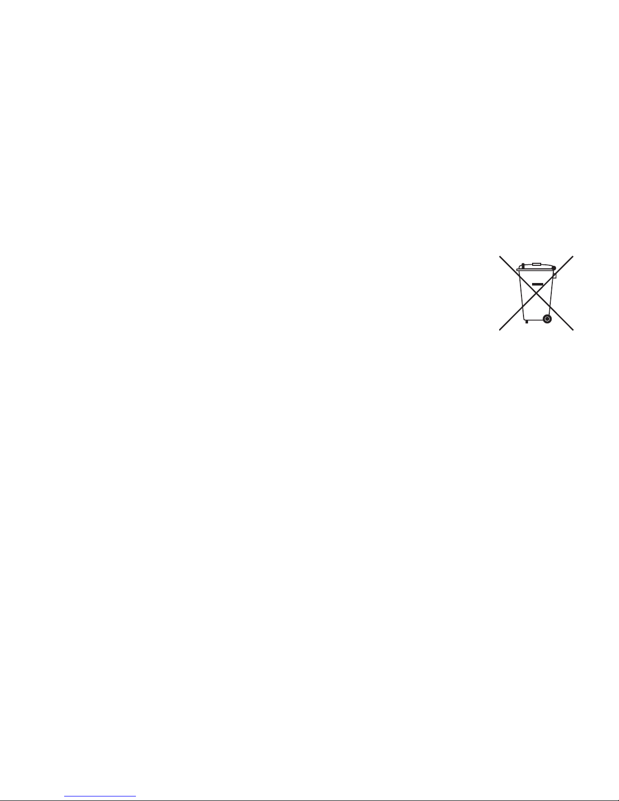
This symbol (WEEE wheelie bin) on product indicates the product must not be disposed of with other household refuse. It must be
disposed of and collected for recycling and recovery of waste EEE. Johnson Outdoors Marine Electronics,
Inc. will mark all EEE products in accordance with the WEEE Directive. It is our goal to comply in the collection, treatment, recovery, and environmentally sound disposal of those products; however, these requirement
do vary within European Union member states. For more information about where you should dispose of your
waste equipment for recycling and recovery and/or your European Union member state requirements, please
contact your dealer or distributor from which your product was purchased.
Disposal:
Minn Kota motors are not subject to the disposal regulations EAG-VO (electric devices directive) that implements
the WEEE directive. Nevertheless never dispose of your Minn Kota motor in a garbage bin but at the proper place of collection of
your local town council.
Never dispose of battery in a garbage bin. Comply with the disposal directions of the manufacturer or his representative and dispose
of them at the proper place of collection of your local town council.
Page 20
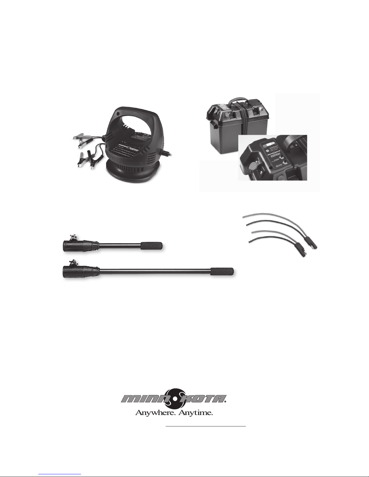
Minn Kota accessories
available for your motor.
Visit our website at www.minnkotamotors.com
Portable Chargers
Power Center
Extension Handles
Quick Plugs
© 2010 Johnson Outdoors Marine Electronics, Inc. P/N 2287101 REV. H ECN 33016 3-11
 Loading...