

Page 1
©2011 Johnson Outdoors Marine Electronics, Inc. All rights reserved.
Conforms to 89/336/EEC (EMC) under standards EN 55022A, EN 50082-2
since 1996 LN V9677264
WARNING: This product contains chemical(s) known to the state of California to cause
cancer and/or reproductive toxicity.
Consumer & Technical Service
Johnson Outdoors Marine Electronics, Inc.
PO Box 8129
121 Power Drive
Mankato, MN 56001
Phone (800) 227-6433
Fax (800) 527-4464
minnkotamotors.com
Part #2197118 ECN 33290 Rev A 8/11
RIPTIDE SE
BOW MOUNT TROLLING MOTOR
CE MASTER USER MANUAL
Page 2
Model: ______________________________________________________________
Serial Number: _______________________________________________________
Purchase Date: ________________________________________________________
Store Where Purchased: ________________________________________________
NOTE: Do not return your Minn Kota motor to your retailer. Your retailer is not authorized to repair or
replace this unit. You may obtain service by: calling Minn Kota at (800) 227-6433; returning your motor
to the Minn Kota Factory Service Center; sending or taking your motor to any Minn Kota authorized
service center on enclosed list.
Please include proof of purchase, serial number and purchase date for warranty service with any of the
above options.
Please thoroughly read this user manual. Follow all instructions and heed all safety and cautionary
notices below. Use of this motor is only permitted for persons that have read and understood these
user instructions. Minors may use this motor only under adult supervision.
ATTENTION: Never run the motor outside the water, as this may result in injuries from the rotating
propeller. Connect motor to battery only if motor is in operating position and the speed-control is in
the zero position. Remove power supply from motor before tilting motor up and propeller out of the
water. When connecting the power-supply cables of the motor to the battery take care that they are
not kinked or subject to chafe and route them in such a way that persons cannot trip over them. Before
using the motor make sure that the insulation of the power cables in not damaged. Disregarding these
safety precautions may result in electric shorts of battery(s) and/or motor. Always disconnect motor
from battery(s) before cleaning or checking the propeller. Avoid submerging the complete motor as
water may enter the lower unit through control head and shaft. If the motor is used while water is
present in the lower unit an electric short will occur and considerable damage to the motor will be the
consequence. This damage will not be covered by warranty.
CAUTION: Take care that neither you nor other persons approach the turning propeller too closely,
neither with body parts nor with objects. The motor is powerful and may endanger or injure you or
others. While the motor is running watch out for persons swimming and for floating objects. Persons
whose ability to run the motor or whose reactions are impaired by alcohol, drugs, medication, or other
substances are not permitted to use this motor. This motor is not suitable for use in strong currents.
The constant noise pressure level of the motor during use is less than 70dB(A). The overall vibration
level does not exceed 2,5m/sec
2
.
minnkotamotors.com
67
THIS PAGE INTENTIOANLLY LEFT BLANK
Page 3
66
Il est dans l’intention de Johnson Outdoors Inc d’être une entreprise citoyenne responsable, fonctionnant
en conformité avec la règlementation environnementale applicable et connue, et d’être un bon voisin dans
les communautés où nous fabriquons ou vendons nos produits.
Directive DEEE :
La directive européenne 2002/96/CE « Directive concernant les déchets d’équipements électriques et
électroniques (DEEE) » a un impact sur la plupart des distributeurs, vendeurs et fabricants d’électronique pour
le grand public au sein de l’Union européenne. La directive DEEE exige que le producteur d’électronique pour le
grand public prenne une part de responsabilité, en ce qui concerne la gestion des déchets de leurs produits, afin
d’atteindre une élimination écologique et ce, tout au long du cycle de vie du produit.
Il se peut que, où vous êtes, vous ne soyez pas tenu d’agir en conformité avec la DEEE pour ce qui est des
équipements électriques et électroniques (EEE), et il se peut qu’il en soit de même pour les EEE conçus et
destinés à être utilisés comme installations fixes ou temporaires dans des véhicules de transport tels que
des automobiles, avions et bâteaux. Dans certains États européens membres de l’Union, ces véhicules
sont considérés comme ne faisant pas partie de ceux qui sont concernés par la directive et l’EEE, puisque
ces applications peuvent être considérées comme exclues de l’exigence de la directive DEEE.
Ce symbole (DEEE poubelle à roulette) sur le produit indique que le produit ne doit
pas être jeté avec les déchets domestiques. Il doit être jeté et collecté pour le recyclage
et la récupération des déchets de l’EEE. Johnson Outdoors Inc va marquer tous les
produits EEE en conformité avec la directive DEEE. C’est notre but de nous conformer
à la collecte, au traitement, à la récupération et à l’élimination écologique judicieuse
de ces produits, mais ces exigences varient au sein des différents États membres de
l’Union européenne. Pour plus d’informations sur l’endroit où vous devez disposer de
vos déchets d’équipements pour le recyclage et la récupération et / ou des exigences
de votre État membre de l’Union européenne, veuillez contacter votre détaillant ou
distributeur duquel vous avez acheté votre produit.
Élimination :
Les moteurs Minn Kota ne sont pas soumis à la loi d’élimination EAG-VO (directive pour les dispositifs
électriques), qui transpose la directive DEEE. Néanmoins, ne jetez jamais votre moteur Minn Kota dans une
poubelle, mais plutôt à l’endroit approprié où s’effectue la collecte dans votre conseil municipal local. Ne
jetez jamais de batteries dans une poubelle. Conformez-vous aux directions d’élimination du fabricant ou
de son représentant et jetez-les à l’endroit approprié où s’effectue la collecte dans votre conseil municipal
local.
DÉCLARATION DE CONFORMITÉ
ENVIRONNEMENTALE
minnkotamotors.com
Features ................................................................................ 4
Mount Installation ................................................................. 5
Battery & Wiring Installation ...............................................10
Motor Wiring Diagram ........................................................14
Using Your Riptide SE ...........................................................15
Tilt and Extension Handle Operation ....................................17
Adjusting the Depth of the Motor ........................................20
Service and Maintenance ......................................................21
Frequently Asked Questions .................................................24
Troubleshooting ...................................................................27
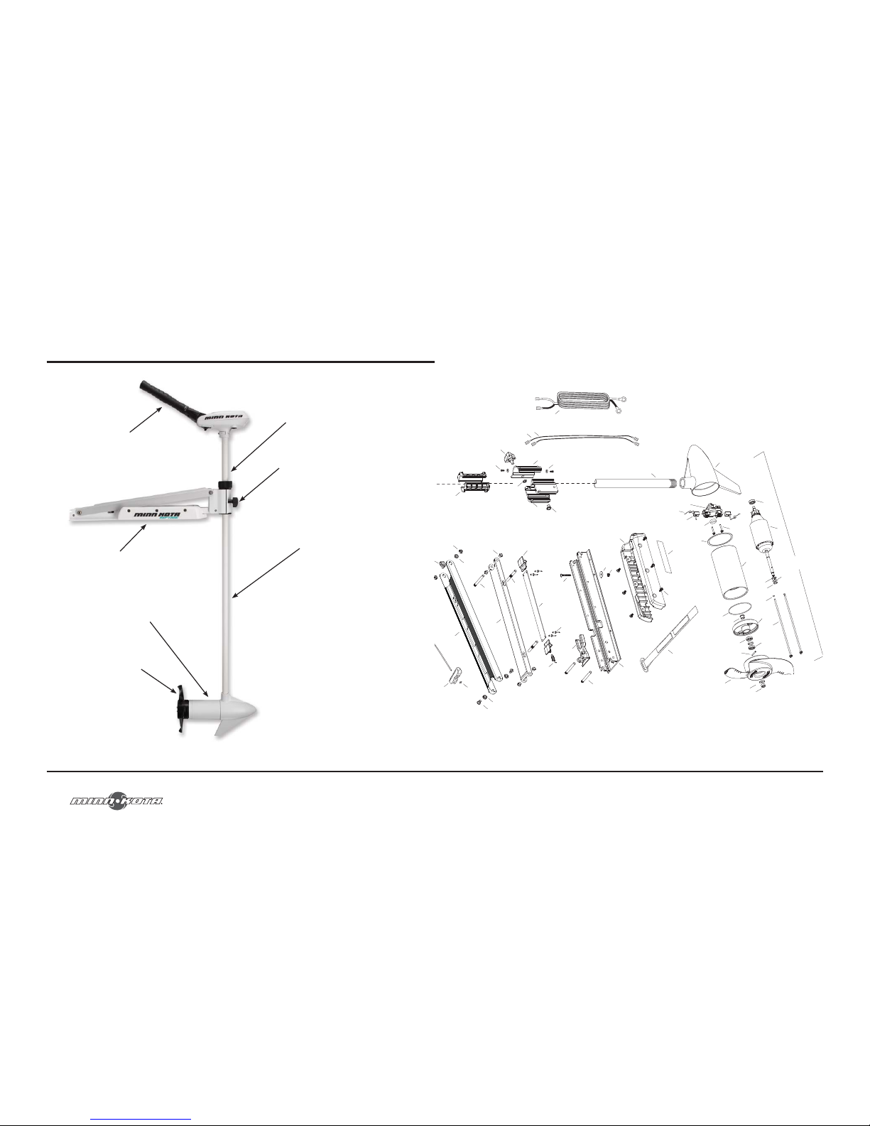
Parts Diagram .......................................................................28
Parts List .............................................................................30
Warranty .............................................................................33
Compliance Statement .........................................................35
TABLE OF CONTENTS
Page 4
4
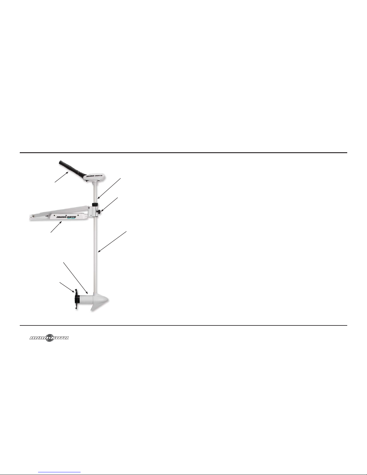
FEATURES
Specifications subject to change without notice.
Tilt Twist Tiller™ Handle
Adjustable
Depth Collar
Steering
Tension Knob
Mounting Bracket
Lifetime Warranty Flexible
Composite Shaft
Propeller
Permanent Magnet,
Cool Power
™
Motor
minnkotamotors.com
65
de garantie peut être organisé en communiquant avec l’un des centres de service agréé Minn Kota® figurant
sur la feuille jointe, ou en communiquant avec la manufacture au : 1-800-227-6433 ou par fax au : 1-800527-4464. Remarque : Ne retournez pas votre moteur ou vos pièces Minn Kota
®
à votre détaillant. Votre
détaillant n’est pas autorisé à les réparer ou à les remplacer.
Il N’Y A AUCUNE GARANTIE EXPRESSE AUTRE QUE CES GARANTIES LIMITÉES. AUCUNE
GARANTIE IMPLICITE (SAUF CELLE POUR LE MANCHE EN COMPOSITE), Y COMPRIS
TOUTE GARANTIE IMPLICITE DE COMMERCIALISATION OU D’ADAPTATION À UN USAGE
PARTICULIER, NE DEVRA EN AUCUN CAS ÊTRE PROLONGÉE AU-DELÀ DES DEUX ANS
SUIVANT LA DATE D’ACHAT. JOHNSON OUTDOORS MARINE ELECTRONICS, INC. NE SERA,
EN AUCUN CAS, TENU POUR RESPONSABLE DES DOMMAGES ACCESSOIRES, INDIRECTS OU
SPÉCIAUX.
Certains états ne permettent pas de limites sur la durée d’une garantie implicite ou l’exclusion ou limitation
des dommages accessoires ou indirects, donc, les limitations ou exclusions ci-dessus peuvent ne pas
s’appliquer à vous. Cette garantie vous donne des droits légaux spécifiques et vous pouvez également
bénéficier d’autres droits qui varient d’un état à l’autre.
Page 5
64
GARANTIE LIMITÉE
Manche en composite
Johnson Outdoors Marine Electronics, Inc. garantit à l’acheteur initial que le manche en composite du moteur
de pêche à la traîne Minn Kota est sans défauts de fabrication et de matériaux qui pourraient apparaître au
cours de la vie de l’acheteur initial. Johnson Outdoors Marine Electronics, Inc. fournira, gratuitement, un
nouveau manche pour remplacer tout manche en composite qui s’avère défectueux après plus de deux (2)
ans suivant la date d’achat. Fournir un tel manche neuf sera la responsabilité unique et exclusive de Johnson
Outdoors Marine Electronics, Inc. et le seul et unique recours de l’acheteur en cas de violation de cette
garantie, et l’acheteur sera responsable de l’installation ou du coût de la main d’œuvre pour l’installation de
tout nouveau manche en composite, fourni par Johnson Outdoors Marine Electronics, Inc.
Produit complet
Johnson Outdoors Marine Electronics, Inc. garantit à l’acheteur initial que son moteur de pêche à la traîne
Minn Kota, en entier, est sans défauts de fabrication et de matériaux qui pourraient apparaître au cours
des deux (2) ans suivant la date d’achat. Johnson Outdoors Marine Electronics, Inc. fournira à son choix,
gratuitement, soit la réparation ou le remplacement de toute pièce y compris tout manche en composite
qui s’avère défectueux au cours des termes de cette garantie. Cette réparation ou remplacement sera la
responsabilité unique et exclusive de Johnson Outdoors Marine Electronics, Inc. et le seul et unique recours
de l’acheteur en cas de violation de cette garantie.
Conditions applicables aux deux garanties
Ces garanties limitées ne s’appliquent pas aux moteurs utilisés commercialement ou en eau salée, pas plus
qu’ils ne couvrent l’usure normale, les imperfections qui n’affectent pas le fonctionnement du moteur, ou
les dommages causés par les accidents, abus, altérations, modifications, utilisations abusives ou mauvais
entretien ou maintenance. LES DOMMAGES AUX MOTEURS CAUSÉS PAR L’UTILISATION D’HÉLICES DE
REMPLACEMENT OU D’AUTRES PIÈCES DE RECHANGE NON CONFORMES AUX SPÉCIFICATIONS
DE CONCEPTION DE L’HÉLICE ET DES PIÈCES ORIGINALES, NE SERONT PAS COUVERTS PAR CETTE
GARANTIE LIMITÉE. Le coût de l’entretien normal ou des pièces de rechange qui ne sont pas défectueuses
sont à la charge de l’acheteur. Pour obtenir le service de garantie aux États-Unis, le moteur ou pièce qui
semble être défectueuse et la preuve d’achat originale (dont la date d’achat), doivent être présentés à un
centre de service agréé Minn Kota
®
ou au centre de service de la manufacture Minn Kota® à Mankato, au MN.
Tous les frais encourus pour des appels de service, le transport ou l’expédition/fret de/vers le centre de
service agréé ou manufacture Minn Kota
®
, la main d’oeuvre pour transporter, retirer, réinstaller ou regréer
des produits retirés pour le service de garantie, ou tout autre élément similaire, sont sous la responsabilité
unique et exclusive de l’acheteur. Les moteurs achetés à l’extérieur des États-Unis (ou les pièces de ces
moteurs) doivent être retournés, port payé avec preuve d’achat (y compris la date d’achat et le numéro de
série), à n’importe quel centre de service agréé Minn Kota
®
dans le pays d’achat. Le service
minnkotamotors.com
5
Tools and Resources Required:
• Phillips Screw Driver
• Drill
• 9/32" Drill Bit
• 7/16" Box End Wrench
• A second person to help with the installation
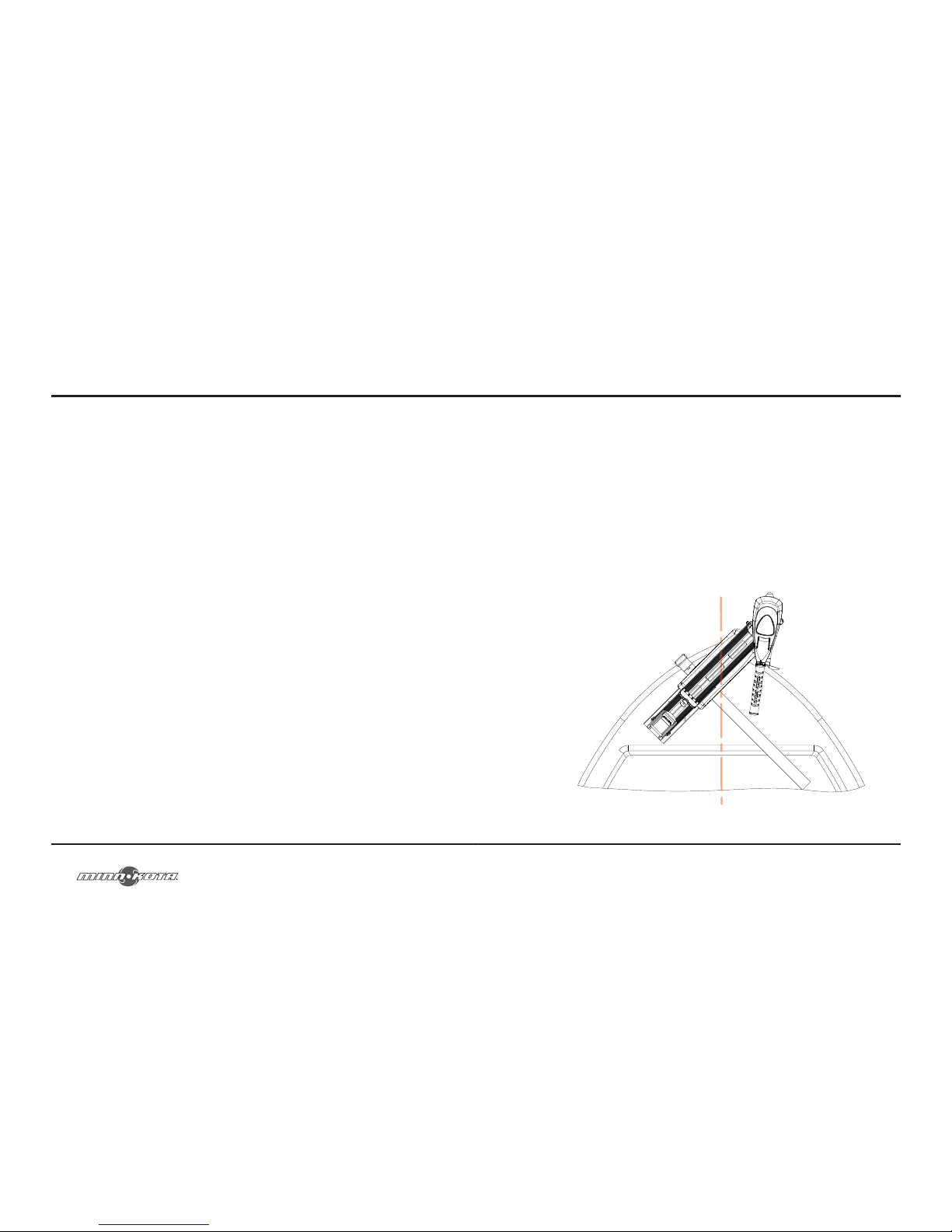
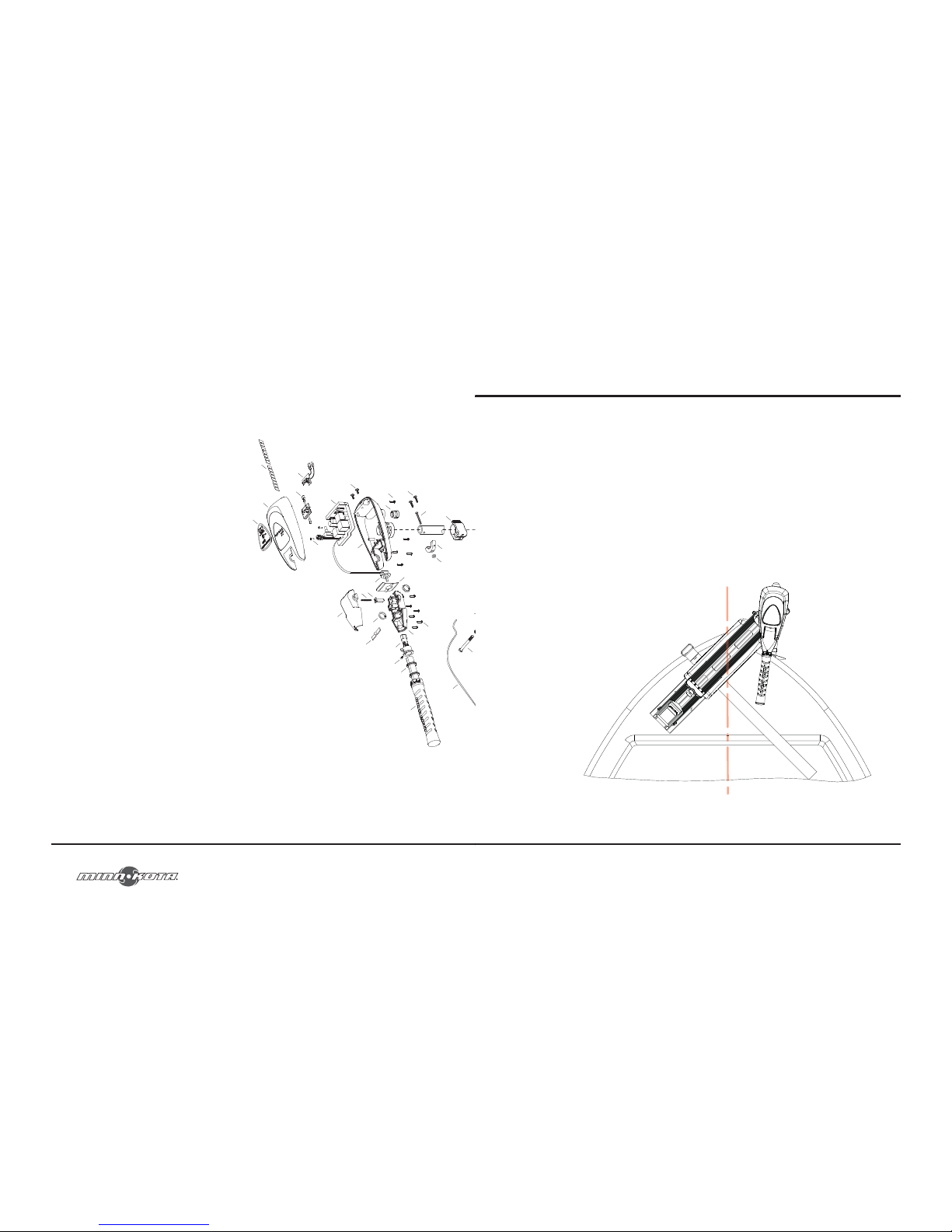
1. Before you proceed determine the desired mounting location for the motor.
It is recommended that the motor be mounted as close to the center line
of the boat as possible, as seen below.
!CAUTION!: Make sure the motor is mounted on a level surface.
MOUNT INSTALLATION
Page 6
6
MOUNT INSTALLATION
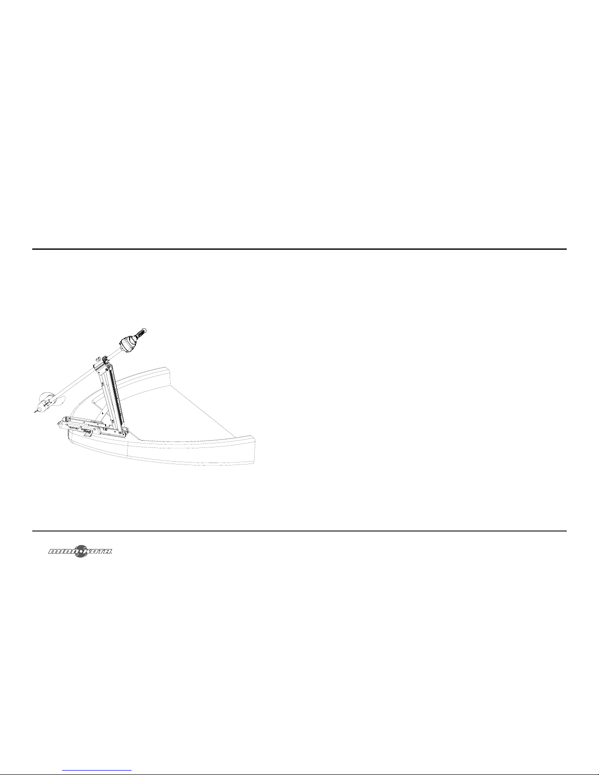
2. Verify the area under the chosen mounting location is clear and safe to drill through.
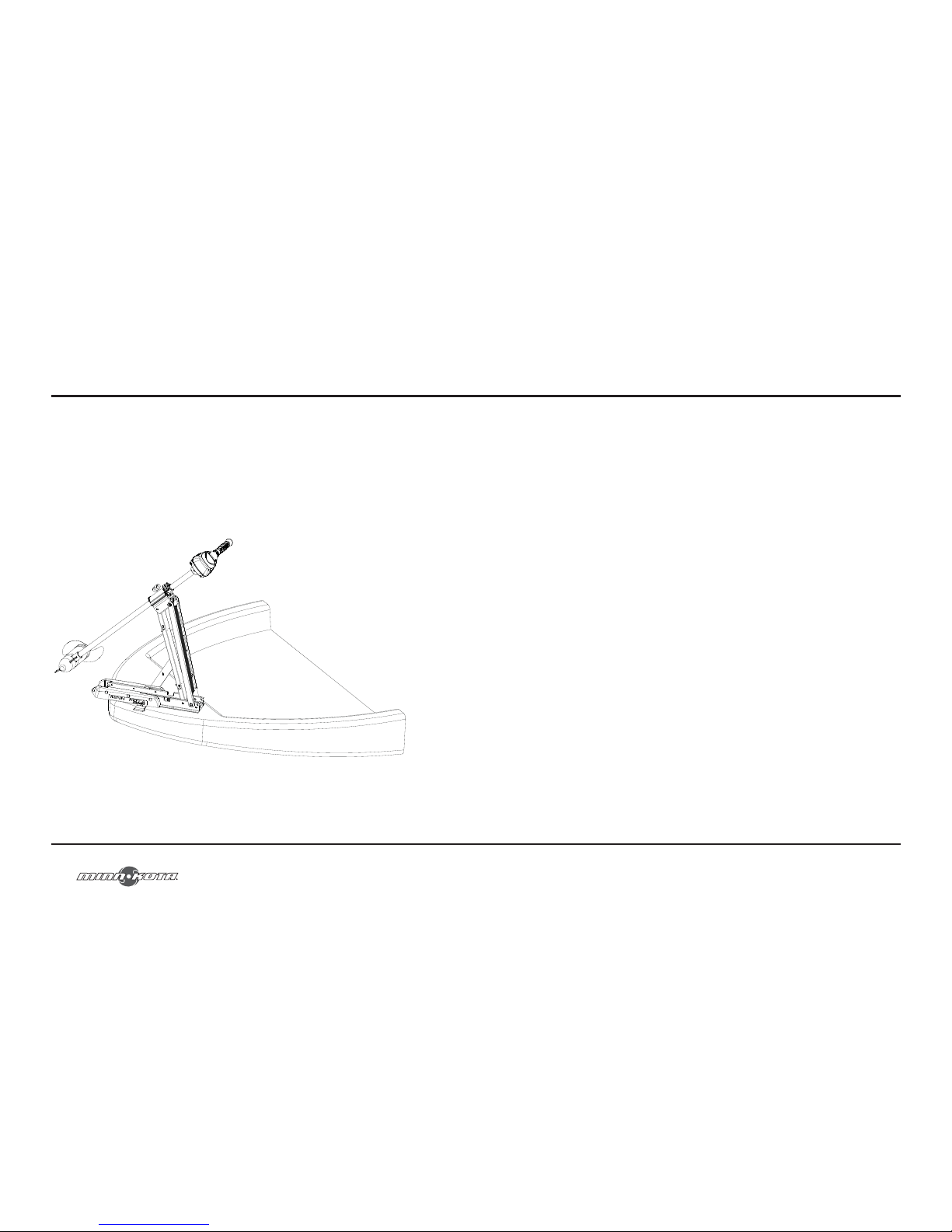
3. Place the motor on top of the desired mounting location while it is in the
stowed position.
4. Verify the motor rest is positioned far enough beyond the edge of the boat so
that the motor clears all obstructions while deploying and stowing the motor.
minnkotamotors.com
63
1. Le moteur ne s’allume pas ou manque de puissance :
• Vérifiez que les raccordements de la batterie respectent les bonnes polarités.
• Assurez-vous que les bornes sont propres et sans corrosion. Utilisez du
papier sablé ou de la toile d’émeri pour nettoyer les bornes.
• Vérifiez le niveau d’eau de la batterie. Ajoutez de l’eau si nécessaire.
2. Le moteur perd de la puissance après avoir fonctionné un court laps de temps :
• Vérifiez la charge de la batterie, si le niveau est bas, remettez-la à pleine charge.
3. Le moteur est difficile à piloter :
• Desserrez le bouton de tension de pilotage sur le support.
• Lubrifier l’arbre en composite.
4. Vous ressentez des vibrations provenant de l’hélice lors du fonctionnement normal :
• Retirez et faite pivoter l’hélice à 180°. Voir les instructions de retrait dans la
section hélice.
REMARQUE : Pour tout autre dysfonctionnement, voir la liste des centres de service
agréés ci-jointe pour le centre de service le plus proche.
DÉPANNAGE
Page 7
62
FOIRE AUX QUESTIONS
Quels sont les avantages d’un moteur électrique monté sur l’étrave?
Les bateaux n’ont pas tendance à aller en ligne droite. Pour cette raison, il est
beaucoup plus facile de tirer un bateau que de le pousser. Il est aussi plus facile de
déplacer l’étrave du bateau latéralement que de déplacer le tableau arrière. Par
conséquent, un moteur électrique monté sur l’étrave permet un bien meilleur contrôle
et positionnement du bateau. Si le contrôle et positionnement rapide du bateau est ce
que vous cherchez, alors vous devez vous procurez un moteur électrique monté sur
l’étrave de Minn Kota™.
Est-ce que le CoPilot va fonctionner avec mon moteur de pêche à
la traîne à commande manuelle ou câblée?
Non, CoPilot est conçu uniquement pour les moteurs à commande électrique.
minnkotamotors.com
7
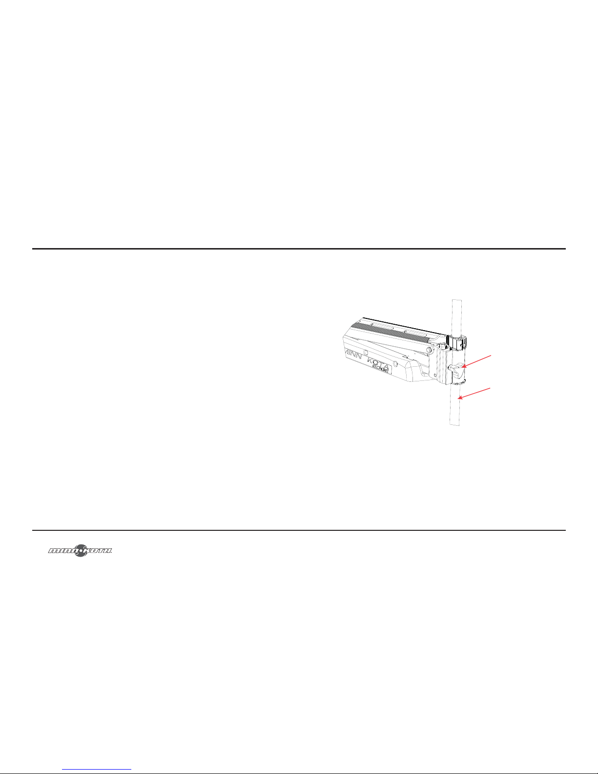
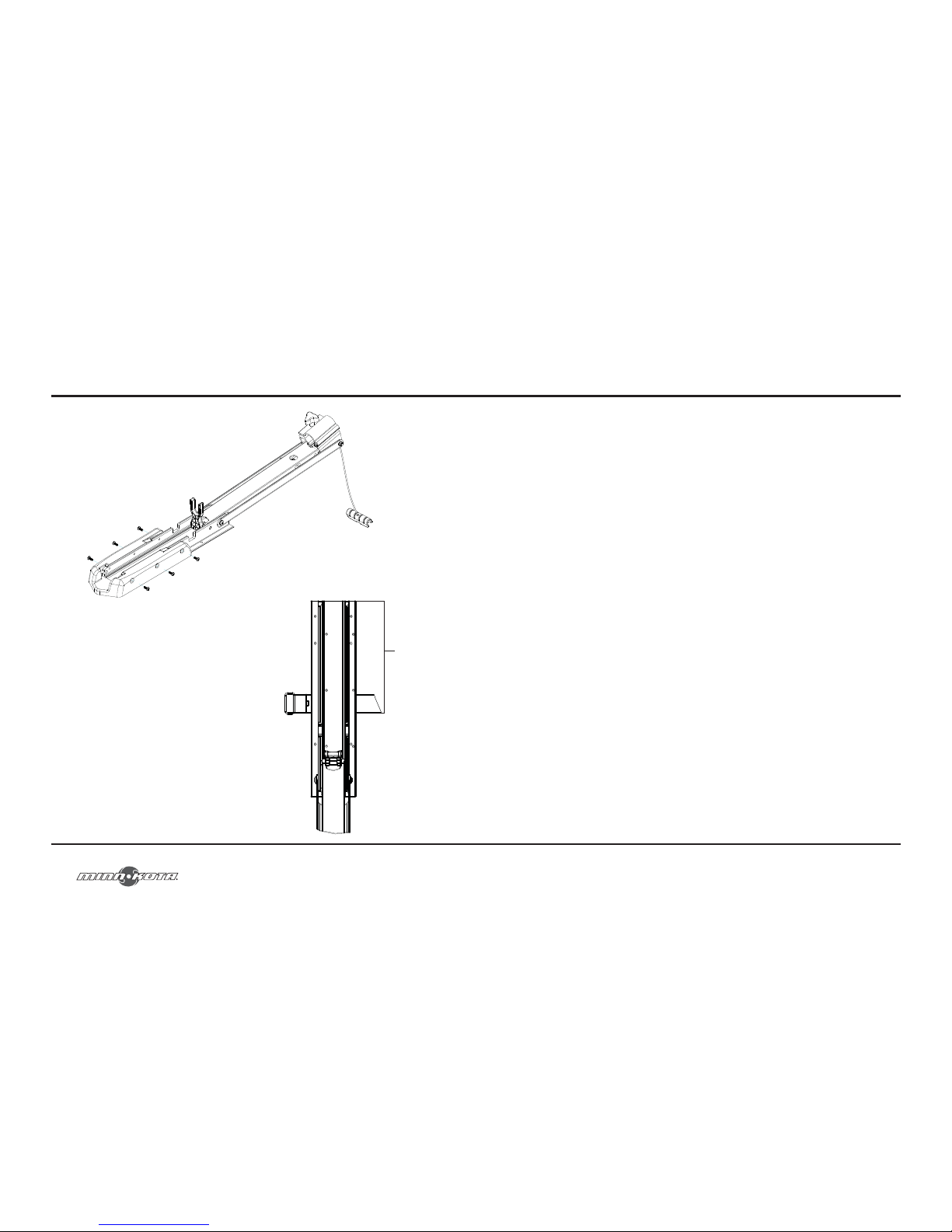
5. Deploy the motor and remove the motor assembly from the mount
by loosening the depth setting knob and opening the door.
Depth Setting Knob
Motor Assembly
!WARNING!: When raising or lowering motor, keep fingers clear of all hinge and
pivot points and all moving parts.
6. Position the mount again in the stowed position.
7. Temporarily remove the Phillips screws that fasten the motor rest to the motor
and remove the motor rest to expose the motor mounting hole pattern.
Page 8
8
MOUNT INSTALLATION
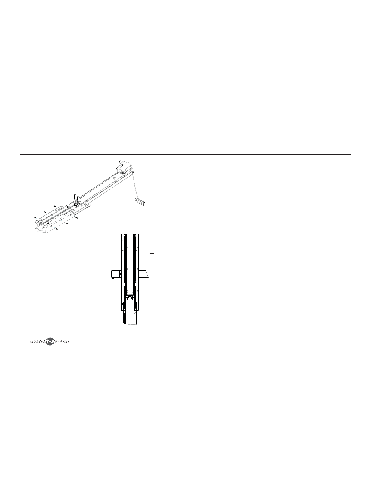
8. Determine the mounting hole pattern you wish
to use from the illustration below. Using the
mounting holes in the mount as your template,
mark the top deck of the boat with a pencil or
an erasable marker.
9. Remove the mount from the deck of the boat
and drill the holes that you marked in the
previous step using a 9/32" drill bit and drill.
Be careful not to damage any wiring or critical
features that may exist under the surface you
are drilling through.
10. Place the mount on the deck of the boat again
and verify the Velcro™ strap is located and
positioned as shown.
15.75"
minnkotamotors.com
61
Puis-je obtenir des pièces de rechange pour mon moteur de
pêche à la traîne Minn Kota™?
Oui, nous serions heureux de vous aider avec ceci. Pour des pièces de rechange aux
États-Unis, veuillez nous contacter au 1-800-227-6433. Au Canada, composez le
1-800-263-6390.
Qu’en est-il de la sélection de la longueur de l’arbre?
Choisir la longueur d’arbre appropriée est important afin que le moteur électrique du
pêcheur n’oscille pas, provoquant ainsi du bruit qui pourrait effrayer les poissons. La
règle de base est que la section du centre du moteur doit être submergée de 22,86 cm
(9”). En général, la sélection de la longueur d’arbre est plus critique avec des moteurs
montés sur l’étrave qu’avec des moteurs montés sur le tableau arrière. La plupart des
tableaux arrière des bateaux sont similaires pour ce qui est de leur distance avec l’eau,
et la longueur des arbres de tableaux arrière standards de Minn Kota™ devrait être
suffisante. Avec des moteurs montés sur l’étrave, il y a beaucoup plus de variations
pour ce qui est des exigences concernant la longueur de l’arbre. Mesurez à partir de la
surface de montage du tableau arrière ou étrave vers le bas et jusqu’au niveau de l’eau.
Ajouter 12,7 cm (5”) à la mesure de la ligne de flottaison pour la pêche dans des eaux
agitées. Ajoutez 30,48 cm (12”) à la mesure de la ligne de flottaison pour le pilotage
d’un moteur à commande manuelle tout en étant debout. Utilisez cette mesure et les
tableaux ci-dessous afin de trouver la longueur d’arbre appropriée.
FOIRE AUX QUESTIONS
Page 9
60
SERVICE ET ENTRETIEN
7. L’hélice anti-algues est conçue pour fonctionner en repoussant complètement
les algues avec un niveau d’efficacité très élevé. Pour maintenir ce haut
rendement, la pointe des lames doit être gardée lisse. Si elles sont rugueuses
ou ébréchées dues au fait de l’utilisation, rendez-les lisses de nouveau à l’aide
de papier sablé fin.
minnkotamotors.com
9
11. Fasten the mount to the deck of the boat using the supplied ¼" – 20 X 2" bolts,
washers and nuts. Tighten the stainless mount hardware securely but slowly to
the deck of the boat using a 7/16" box end wrench. Tightening the stainless
hardware too fast may result in galling and or seizing of the bolts and nuts.
12. Reinstall the motor rest using the six original ¼" Phillips screws.
13. Reinstall the motor assembly into the mount and securely tighten the depth
adjustment knob.
Page 10
10
Boat Rigging & Product Installation:
For safety and compliance reasons, we recommend that you follow American Boat and
Yacht Council (ABYC) standards when rigging your boat. Altering boat wiring should
be completed by a qualified marine technician. The following specifications are for
general guidelines only:
!CAUTION!: These guidelines apply to general rigging to support your Minn Kota
Motor. Powering multiple motors or additional electrical devices from the same power
circuit may impact the recommended conductor gauge and circuit breaker size. If you
are using wire longer than that provided with your unit, follow the conductor gauge and
circuit breaker sizing table below. If your total conductor length is more than 50 feet we
recommend that you contact a qualified marine technician.
An over-current protection device (circuit breaker or fuse) must be used. Coast Guard
requirements dictate that each ungrounded current-carrying conductor must be
protected by a manually reset, trip-free circuit breaker or fuse. The type (voltage and
current rating) of the fuse or circuit breaker must be sized accordingly to the trolling
motor used. The table below gives recommended guidelines for circuit breaker sizing.
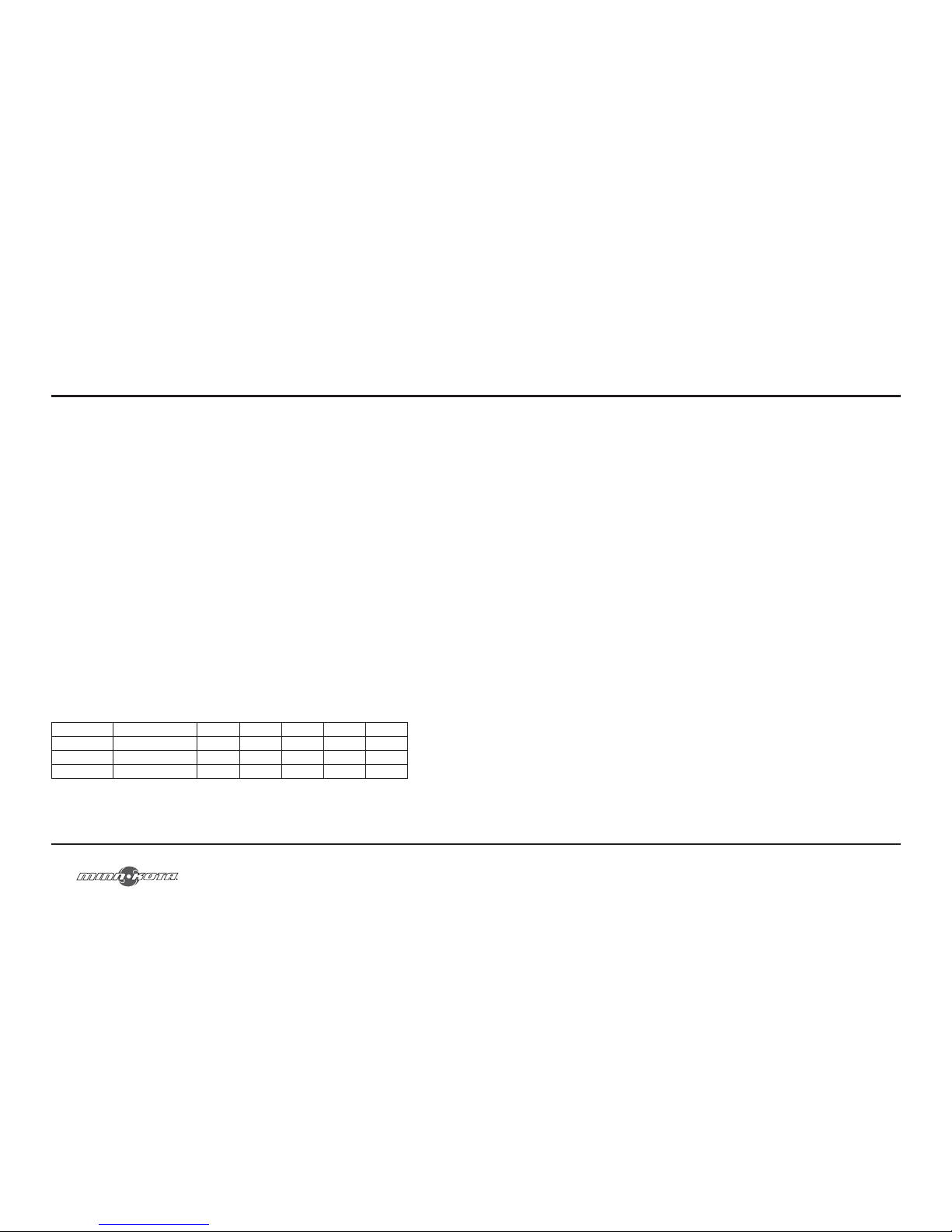
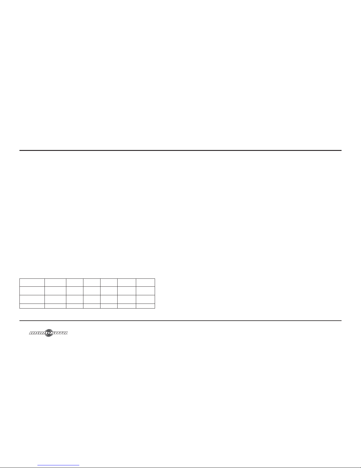
Conductor Gauge and Circuit Breaker Sizing Table
Total Conductor Length (length of all conductors in the total circuit)
Motor Thrust Circuit Breaker 10 feet 20 feet 30 feet 40 feet 50 feet
40#, 45# 50 Amp @ 12 VDC 10 AWG 8 AWG 6 AWG 4 AWG 4 AWG
50#, 55# 60 Amp @ 12 VDC 8 AWG 6 AWG 4 AWG 4 AWG 2 AWG
70# 50 Amp @ 24 VDC 10 AWG 10 AWG 8 AWG 8 AWG 6 AWG
*The conductor and circuit breaker sizing table above is only valid for the following assumptions.
BATTERY & WIRING INSTALLATION
minnkotamotors.com
59
Maximizer™ : (Sur certains modèles)
L’électronique intégrée dans le Maximizer crée des impulsions avec modulation afin
de permettre un temps de fonctionnement plus long et prolonger la vie de la batterie.
Dans certaines applications du contrôle de vitesse du Maximizer, il se peut que vous
expérimentiez de l’interférence sur l’écran de votre sondeur. Nous recommandons que
vous utilisiez une batterie marine à décharge profonde séparée, pour votre moteur de
pêche à la traîne, et que vous alimentiez le sondeur avec la batterie de démarrage/initiale.
Si les problèmes persistent, appelez notre département de service au : 1-800-227-6433.
Entretien général
1. Après utilisation, le moteur en entier devrait être rincé avec de l’eau douce,
puis essuyé avec un chiffon imbibé d’un protecteur à base de silicone aqueux
telles que Armor All™.
2. L’hélice doit être inspectée et les algues et lignes de pêche ôtées, toutes les
20 heures de fonctionnement. Les lignes de pêche et les algues peuvent
se retrouver derrière l’hélice, endommager les joints et permettre à l’eau
d’entrer dans le moteur.
3. Chaque fois que le moteur est utilisé, assurez-vous que l’écrou de l’hélice est
bien serré.
4. Afin de prévenir les dommages accidentels, lors du transport ou de
l’entreposage, débranchez la batterie lorsque le moteur est hors de l’eau.
Pour un entreposage prolongé, enduire légèrement toutes les parties
métalliques avec un protecteur à base de silicone aqueux.
5. Pour profiter de la durée de vie maximale de la batterie, rechargez la ou les
batteries dès que possible après utilisation. Pour une performance maximale
du moteur, rechargez la batterie complètement avant de l’utiliser.
6. Gardez les bornes de la batterie propres à l’aide de papier sablé fin ou de
toile d’émeri.
Page 11
58
SERVICE ET ENTRETIEN
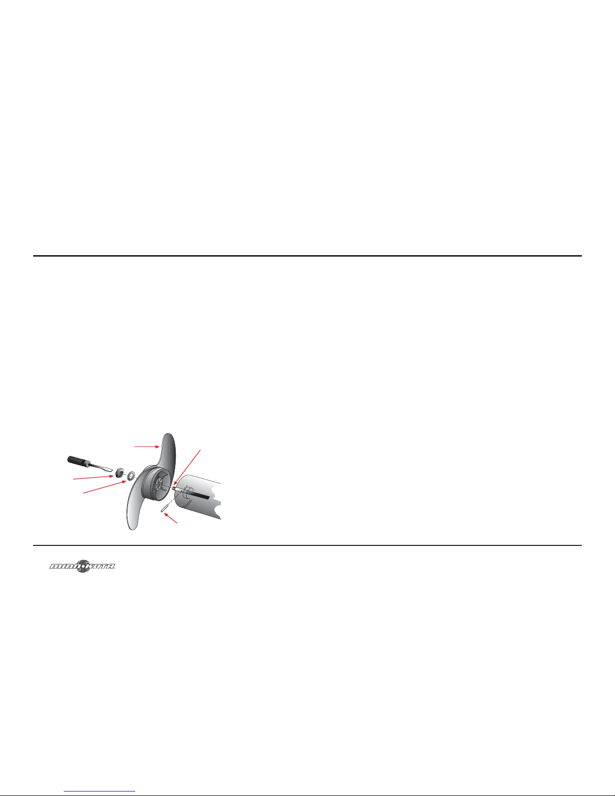
Remplacement de l’hélice
AVERTISSEMENT! : DÉBRANCHEZ LE MOTEUR DE LA BATTERIE
AVANT D’ENTREPRENDRE TOUT TRAVAIL OU ENTRETIEN SUR L’HÉLICE.
1. Débranchez le moteur de toutes les sources d’alimentation avant de changer l’hélice.
2. Maintenez l’hélice et desserrer l’anode/écrou à l’aide d’une clé.
3. Retirez l’anode/écrou et la rondelle. Si la goupille est cisaillée ou cassée, vous
devrez tenir l’arbre stable avec un tournevis à lame enfoncé dans la fente à
l’extrémité de l’arbre.
4. Tournez la vieille hélice à l’horizontale (telle qu’illustré) et retirez-la sans hésiter. Si
la goupille tombe, repoussez-la à l’intérieur.
5. Alignez la nouvelle hélice avec la goupille.
6. Installez la rondelle et l’anode/écrou de l’hélice.
7. Serrez l’anode/écrou de l’hélice ... tour de plus passé le serrage confortable
[2,825-3,954 Nm.(25-35 inch lbs)] Ne serrez pas trop car cela peut
endommager l’hélice.
Hélice anti-algues
Anode/Écrou
Rondelle
Goupille
Fente à l’extrémité
minnkotamotors.com
11
1. No more than 3 conductors are bundled together inside of a sheath or conduit
outside of engine spaces.
2. Each conductor has 105°C temp rated insulation.
3. No more than 5% voltage drop allowed at full motor power based on published
product power requirements.
Reference:
United States Code of Federal Regulations: 33 CFR 183 – Boats and Associated Equipment
ABYC E-11: AC and DC Electrical Systems on Boats
Selecting the Correct Batteries
The motor will operate with any deep cycle marine 12 volt battery/batteries. For
best results use a deep cycle, marine battery with at least a 115 ampere hour rating.
As a general on the water estimate, your 12 volt motor will draw one ampere per
hour and your 24 volt motor will draw .75 ampere per hour for each pound of thrust
produced when the motor is running on high. The actual ampere draw is subject
to your particular environmental conditions and operation requirements. Maintain
battery at full charge. Proper care will ensure having battery power when you need
it, and will significantly improve the battery life. Failure to recharge lead-acid batteries
(within 12-24 hours) is the leading cause of premature battery failure. Use a variable
rate charger to avoid overcharging. If you are using a crank battery to start a gasoline
outboard, we recommend that you use a separate deep cycle marine battery/
batteries for your Minn Kota trolling motor.
Page 12
12
BATTERY & WIRING INSTALLATION
Advice Regarding Batteries:
Never connect the (+) and the (–) terminals of the battery together. Take care
that no metal object can fall onto the battery and short the terminals. This would
immediately lead to a short and utmost fire danger.
Recommendation:
Use battery boxes and covered battery terminal clamps like Minn Kota accessory
#MK-BC-1.
How to Connect the Batteries
12 Volt Systems:
1. Make sure that the motor is switched off (speed selector on “0”).
2. Connect positive ( + ) red lead to positive ( + ) battery terminal.
3. Connect negative ( – ) black lead to negative ( – ) battery terminal.
4. For safety reasons do not switch the motor on until the propeller is in the water.
24 Volt Systems:
1. Make sure that the motor is switched off (speed selector on “0”).
2. Two 12 volt batteries are required.
3. The batteries must be wired in series, only as directed in wiring diagram,
to provide 24 volts.
a. Connect a connector cable to the positive ( + ) terminal of battery 1 and
to the negative ( – ) terminal of battery 2.
b. Connect positive ( + ) red lead to positive ( + ) terminal on battery 2.
c. Connect negative ( – ) black lead to negative ( – ) terminal of battery 1.
minnkotamotors.com
57
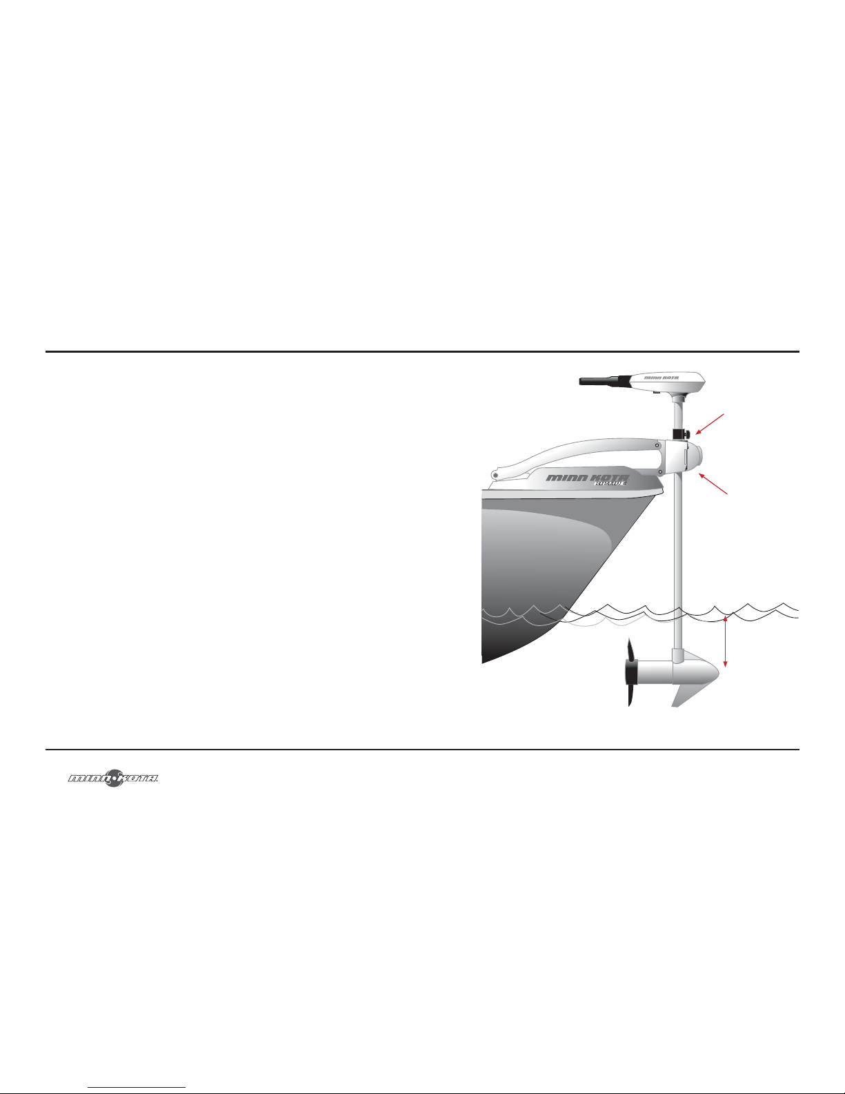
Bouton circulaire de profondeur
Bouton du couvercle
à charnière
Minimum de 30,48 cm (12”)
Page 13
56
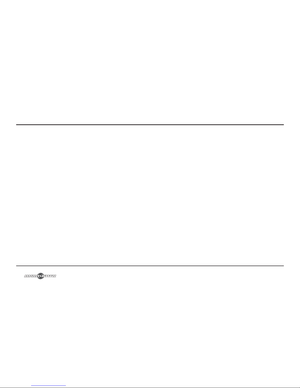
AJUSTER LA PROFONDEUR DU MOTEUR
1. Assurez-vous que l’arbre en composite peut glisser et pivoter librement. Sur
les moteurs qui sont équipés ainsi, il peut être nécessaire d’ajuster la tension
sur le bouton du couvercle à charnière. Si ce bouton est réglé trop serré, il
peut interférer avec le réglage de profondeur et la direction.
2. Empoignez fermement l’arbre ou la tête de contrôle et gardez-la stable.
3. Desserrez le bouton circulaire de profondeur jusqu’à ce que la bague glisse
librement.
4. Remontez ou abaissez le moteur à la profondeur désirée. Serrez le ou les boutons
afin de fixer la bague et le moteur en place.
REMARQUE : Lors du réglage de la profondeur assurez-vous que le haut du moteur
est immergé à au moins 30,5 cm (12”) afin d’éviter de brasser ou d’agiter l’eau à
la surface. L’hélice doit être complètement submergée. N’utilisez jamais le moteur
lorsqu’il est hors de l’eau.
minnkotamotors.com
13
4. For safety reasons do not switch the motor on until the propeller is in the water. If
installing a leadwire plug, observe proper polarity and follow instructions in your
boat owner’s manual. See wiring diagram on following pages.
!CAUTION!
• IMPROPER WIRING OF 24/36 VOLT SYSTEMS COULD CAUSE
BATTERY EXPLOSION!
• KEEP LEADWIRE WING NUT CONNECTION TIGHT AND SOLID TO
BATTERY TERMINALS.
• LOCATE BATTERY IN A VENTILATED COMPARTMENT.
Page 14
14
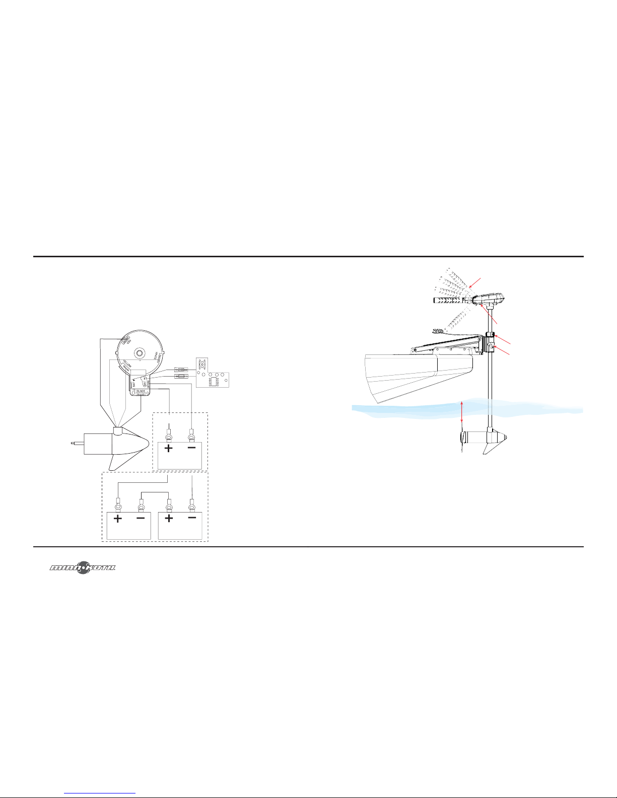
THIS IS A UNIVERSAL MULTI-VOLTAGE DIAGRAM. DOUBLE CHECK YOUR
MOTORS VOLTAGE FOR PROPER CONNECTIONS.
Over-Current Protection Devices not shown in illustrations.
MOTOR WIRING DIAGRAM
12v
24v
FIVE SPEED SWITCH
minnkotamotors.com
55
Relâcher le bouton
La poignée contrôle
DE/SUR, La direction et en avant/inverse
Col de profondeur
Le bouton de tension
de direction
30.48 cm ( 12”)
Profondeur minimum
ATTENTION! : N’UTILISEZ JAMAIS VOTRE MOTEUR LORSQU’IL EST
HORS DE L’EAU.
Page 15
54
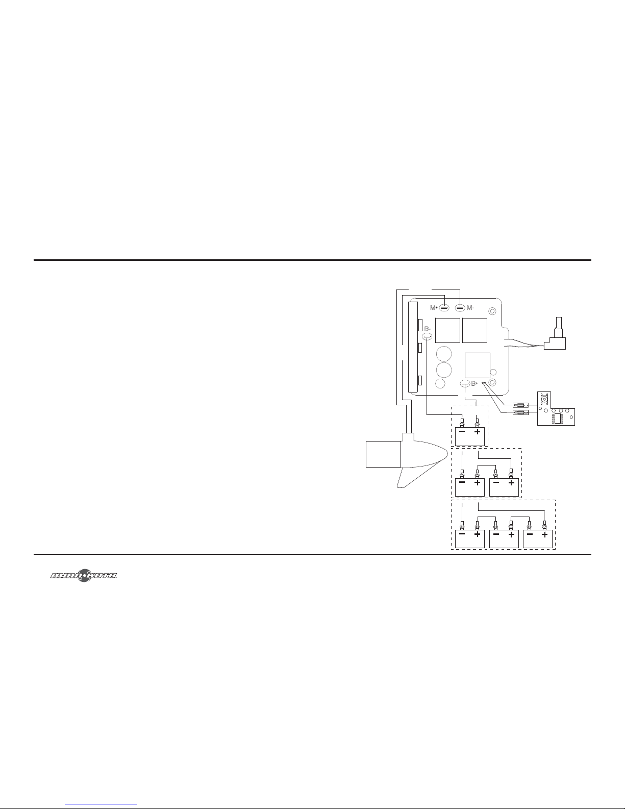
Votre moteur de pêche à la traîne Riptide SE dispose d’une poignée permettant 7
positions d’inclinaison ... De 45°, 30° et 15° vers le haut et le bas à part de la position
(horizontale) de 0°. Pour utiliser les positions vers le bas, vous devez tout d’abord
appuyer sur le bouton de déverrouillage situé sur la partie inférieure à gauche de la
poignée de pivot.
La poignée de votre moteur de pêche à la traîne Riptide SE dispose également d’une
position d’arrimage unique, qui est utile pour limiter la quantité d’espace requis pour
l’entreposage ou le transport.
Appuyez d’abord sur le bouton de déverrouillage situé sur la partie inférieure à gauche
de la poignée de pivot, puis poussez la poignée vers le bas jusqu’à ce que vous sentiez
la poignée « verrouillée » en position d’arrimage. Ce sera presque parallèle à l’arbre du
moteur.
Pour allonger la poignée, tirez la poignée vers vous jusqu’à la position désirée. La
poignée s’allongera d’un bon 15,24 cm (6”). Pour rétracter, poussez la poignée jusqu’à
ce qu’elle atteigne l’avant de la tête de contrôle du moteur.
IMPORTANT : POUR UTILISER LA POSITION D’ARRIMAGE, LE MOTEUR
DOIT ÊTRE EN POSITION D’ARRÊT! NE PAS METTRE LE MOTEUR EN
POSITION D’ARRÊT AVANT D’ARRIMER LA POIGNÉE CAUSERA UNE
DÉFAILLANCE GÉNÉRALE.
FONCTIONNEMENT DE LA POIGNÉE
D’INCLINAISON ET D’EXTENSION
minnkotamotors.com
15
12v
24v
36v
RED M+
BLACK M - CONTROL BOARD
BLACK
BATTERY GAUGE
12V BATT 1
BLACK B-
RED B+
MOTOR
SPEED ADJUSTMENT KNOB
12V BATT 1
12V BATT 1
12V BATT 2
12V BATT 3
12V BATT 2
RED
VARIABLE SPEED SWITCH
Page 16
16
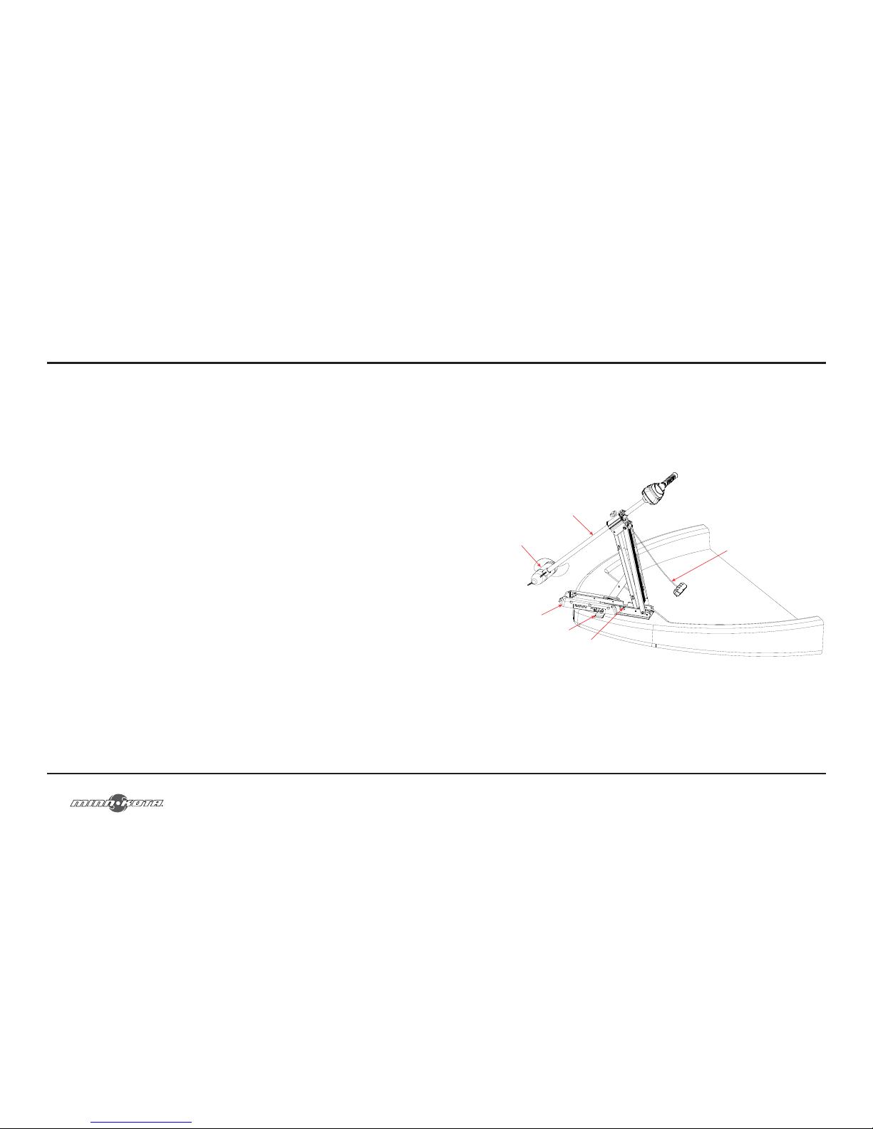
Stowing and Deploying the Motor
!WARNING!: When raising or lowering the motor, keep fingers clear
of all hinge and pivot points and all moving parts.
Mount Features
• The Edge mount is designed to fold back and lock the motor flat on the
deck when not in use and to provide secure stowage for transport.
• The pull grip and rope releases the lock bar, which automatically engages
when the unit is lowered or raised into position. The pull grip and rope
should be used to both lower and raise the unit.
• The motor rest positions the lower unit as it comes in contact with the
nose of the mount and guides it onto the motor rest.
• The tube lock captures the motor shaft and keeps the lower unit centered
on the motor rest.
• The Velcro strap must be used to place pressure on the motor shaft to
hold the lower unit tightly against the motor rest when stowed.
• The pull grip and rope can be stored by placing the pull grip on top of the
tube lock or into the rope stow slot on the control box of the motor.
To Deploy the Motor
Simply pull back and lift the motor off of the mount with the pull grip and rope.
Lower the motor into the water using the pull grip and rope. The motor will lock
into the deployed position automatically.
USING YOUR RIPTIDE SE
minnkotamotors.com
53
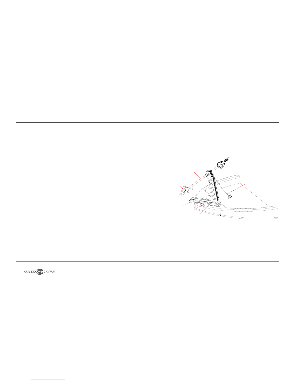
Pour arrimer le moteur
Vous n’avez qu’à tirer et soulever le moteur hors de l’eau à l’aide de la poignée et
corde de traction. Abaissez l’unité inférieure sur le support du moteur à l’aide de
la poignée et corde de traction. Le moteur va se verrouiller en position arrimée
automatiquement. Enroulez la sangle de Velcro au-dessus du sommet de l’arbre du
moteur afin de fixer le moteur.
Arbre moteur
Abaisser l'unit
Repos moteur
Le velcro sangle
Serrure de tube
Tirer la poigne et la corde
Page 17
52
L’arrimage et le déploiement du moteur
AVERTISSEMENT! : Lorsque vous remontez ou abaissez le moteur, gardez
vos doigts loin de toutes charnières et points de pivot et de toutes pièces mobiles.
Caractéristiques du support
• Le support Edge est conçu pour se replier et verrouiller le moteur à plat sur
le pont, lorsqu’il n’est pas utilisé, et pour fournir un arrimage sûr pour le
transport.
• La poignée et corde de traction libère la barre de verrouillage, qui s’active
automatiquement lorsque l’appareil est abaissé ou élevé en position. La
poignée et corde de traction doit être utilisée à la fois pour abaisser et
remonter l’appareil.
• Le support du moteur positionne l’appareil inférieur puisqu’il se retrouve
en contact avec le nez du support et le guide sur le support du moteur.
• Le verrouillage du tube retient l’arbre du moteur et maintient l’unité
inférieure centrée sur le support du moteur.
• La sangle de Velcro doit être utilisée pour faire de la pression sur l’arbre
du moteur afin de fixer solidement l’unité inférieure au support du
moteur lorsqu’il est arrimé.
• La poignée et corde de traction peut être entreposée en plaçant la
poignée de traction sur le dessus du tube de verrouillage ou dans la fente
de rangement de la corde sur le boîtier de commande du moteur.
Pour déployer le moteur
Vous n’avez qu’à tirer et soulever le moteur hors du support à l’aide de la poignée et
corde de traction. Abaisser le moteur dans l’eau en utilisant la poignée et corde de
traction. Le moteur va se verrouiller en position déployée automatiquement.
UTILISATION DE VOTRE RIPTIDE SE
minnkotamotors.com
17
To Stow the Motor
Pull back and lift the motor out of the water with the pull grip and rope. Lower the
lower unit onto the motor rest using the pull grip and rope. The motor will lock into
the stowed position automatically. Wrap the Velcro strap over top of the motor shaft
to secure the motor.
Motor Shaft
Lower Unit
Motor Rest
Velcro Strap
Tube Lock
Pull Grip and Rope
Page 18
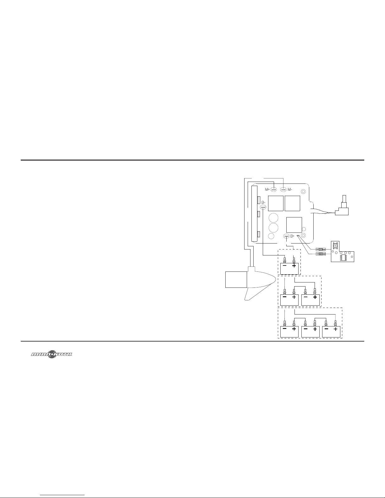
18
TILT AND EXTENSION HANDLE OPERATION
Your Riptide SE trolling motor features 7 usable handle tilt positions... 45°, 30°, and
15° up and down from the 0° (horizontal) position. To use the down positions, you
must first press the release button located on the left underside of the pivot handle.
Your Riptide SE trolling motor handle also features a unique stow position, that is useful
for limiting the amount of space required for storage or travel.
First press the release button located on the left underside of the pivot handle, then
push the handle down until you feel the handle “lock in” to the stowed position. This
will be almost parallel to the motor shaft.
To extend the handle, pull the handle towards you to the desired position. The handle
will extend a full 6 inches. To retract, push the handle in until it meets the face of the
motor control head.
IMPORTANT: THE MOTOR MUST BE IN THE OFF POSITION TO USE THE
STOW POSITION! FAILURE TO PUT THE MOTOR IN THE OFF POSITION
BEFORE STOWING THE HANDLE WILL RESULT IN JOINT FAILURE.
minnkotamotors.com
51
12v
24v
36v
M + ROUGE
M – NOIR TABLEAU DE CONTRÔLE
NOIR
JAUGE DE LA BATTERIE
BATTERIE
12 V 1
B – NOIR
B + ROUGE
MOTEUR
BOUTON DE RÉGLAGE DES VITESSES
ROUGE
COMMUTATEUR DE VITESSE VARIABLE
BATTERIE
12 V 1
BATTERIE
12 V 1
BATTERIE
12 V 2
BATTERIE
12 V 3
BATTERIE
12 V 2
Page 19
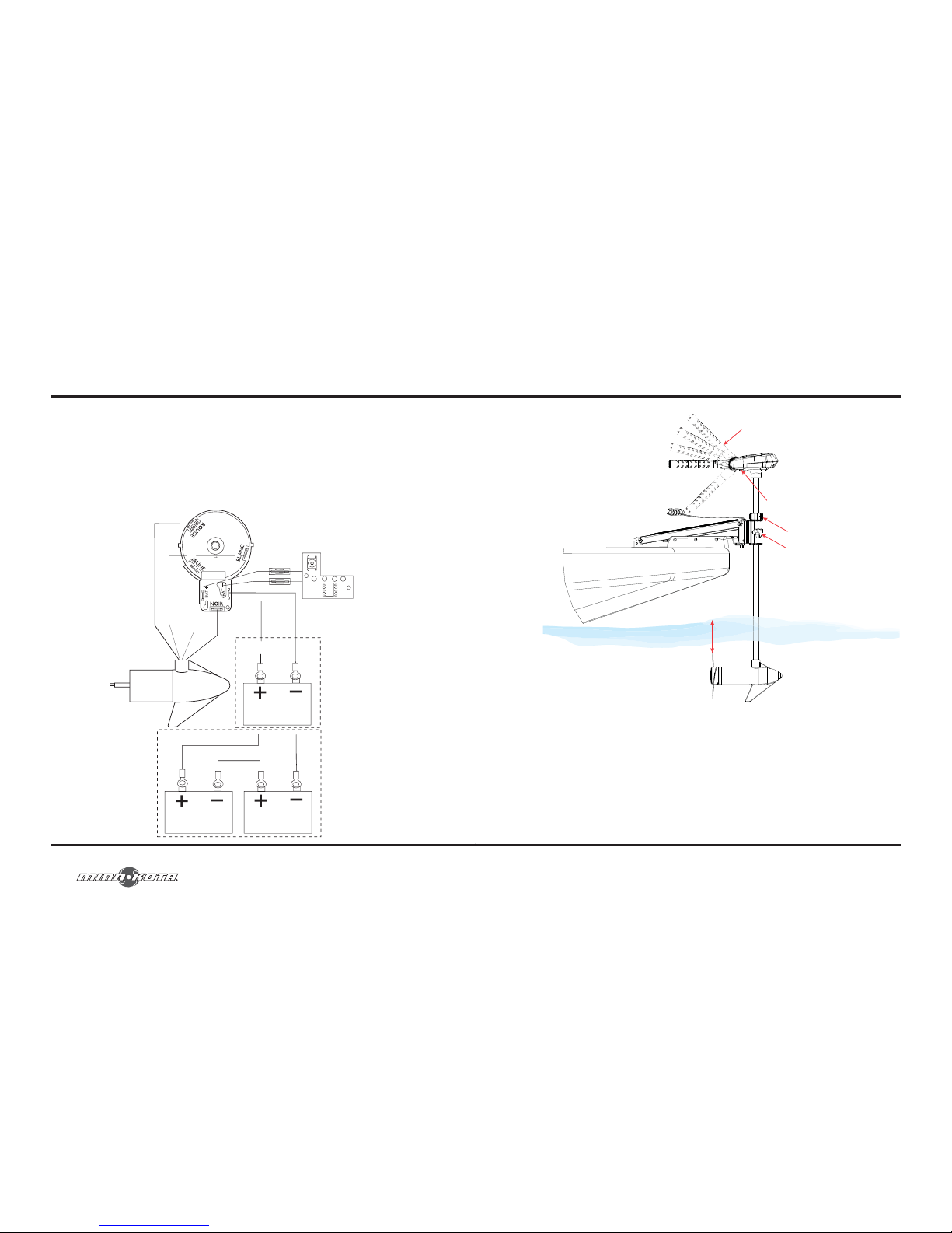
50
TIL S’AGIT D’UN SCHÉMA DE MULTI-TENSIONS UNIVERSEL. REVÉRIFIEZ LA TENSION
DE VOS MOTEURS AFIN D’EFFECTUER LES RACCORDEMENTS APPROPRIÉS.
Les dispositifs de protection contre les surintensités ne figurent pas dans les illustrations.
SCHÉMA DE CÂBLAGE DU MOTEUR
12v
24v
COMMUTATEUR À CINQ VITESSES
minnkotamotors.com
19
Release Button
Handle Controls
OFF/ON, Steering and Forward/Reverse
Depth Collar
Steering Tension Knob
12” Minimum Depth
!CAUTION!: NEVER OPERATE YOUR MOTOR WHEN IT IS OUT OF
THE WATER.
Page 20
20
ADJUSTING THE DEPTH OF THE MOTOR
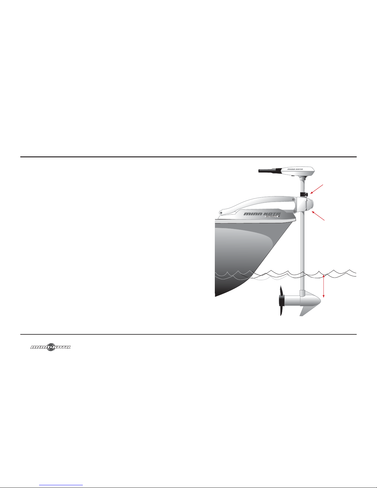
1. Make sure that the composite shaft is able to slide up and rotate freely.
On motors so equipped, it may be necessary to adjust the tension on the hinged
cover knob. If this knob is set too tight, it can interfere with depth adjustment
and with steering.
2. Firmly grasp the shaft or control head and hold it steady.
3. Loosen the depth collar knob until the collar slides freely.
4. Raise or lower the motor to the desired depth. Tighten the knob(s) to secure
the collar and motor in place.
NOTE: When setting the depth be sure the top of the motor is submerged at least
12" to avoid churning or agitation of surface water. The propeller must be completely
submerged. Never operate the motor when it is out of the water.
minnkotamotors.com
49
4. Pour des raisons de sécurité, n’allumez pas le moteur jusqu’à ce que l’hélice
soit dans l’eau. Si vous installez un raccordement en fil de plomb, respectez les
polarités appropriées et suivez les instructions qui se trouvent dans votre manuel
du propriétaire du bateau. Voir le schéma de câblage sur les pages suivantes.
!ATTENTION!
• UNE MAUVAISE INSTALLATION DU CÂBLAGE DES SYSTÈMES DE
24/36 VOLTS POURRAIT PROVOQUER UNE EXPLOSION DES
BATTERIES!
• GARDEZ LES ÉCROUS PAPILLONS DE RACCORDEMENT SOLIDES ET
BIEN SERRÉS AUTOUR DES BORNES DE LA BATTERIE.
• INSTALLEZ LA BATTERIE DANS UN COMPARTIMENT VENTILÉ.
Page 21
48
INSTALLATION DES BATTERIES ET DU CÂBLAGE
Conseils concernant les batteries :
Ne branchez jamais les bornes (+) et (–) de la batterie ensemble. Prenez soin
qu’aucun objet métallique ne puisse tomber sur la batterie et provoquer un courtcircuit aux bornes. Cela provoquerait immédiatement un court-circuit et un risque
d’incendie extrême.
Recommandation : Utilisez les boîtes de batterie et les pinces de raccordement de
batterie isolées Minn Kota™, tel que l’accessoire #MK-BC-1.
Comment brancher les batteries
Systèmes de 12 volts :
1. Assurez-vous que le moteur est éteint (sélecteur de vitesse sur « 0 »).
2. Branchez le fil rouge positif (+) à la borne positive (+) de la batterie.
3. Branchez le fil noir négatif (–) à la borne négative (–) de la batterie.
4. Pour des raisons de sécurité, n’allumez pas le moteur jusqu’à ce que l’hélice soit
dans l’eau.
Systèmes de 24 volts :
1. Assurez-vous que le moteur est éteint (sélecteur de vitesse sur « 0 »).
2. Deux batteries de 12 volts sont nécessaires.
3. Les batteries doivent être branchées en série, uniquement tel qu’illustré dans le
schéma de câblage, afin de fournir 24 volts.
a. Branchez un câble de raccordement à la borne positive (+) de la batterie 1
et à la borne négative (–) de la batterie 2.
b. Branchez le fil rouge positif (+) à la borne positive (+) sur la batterie 2.
c. Branchez le fil noir négatif (–) à la borne négative (–) de la batterie 1.
minnkotamotors.com
21
Depth Collar Knob
Hinged Cover Knob
12" Minimum
Page 22
22
SERVICE & MAINTENANCE
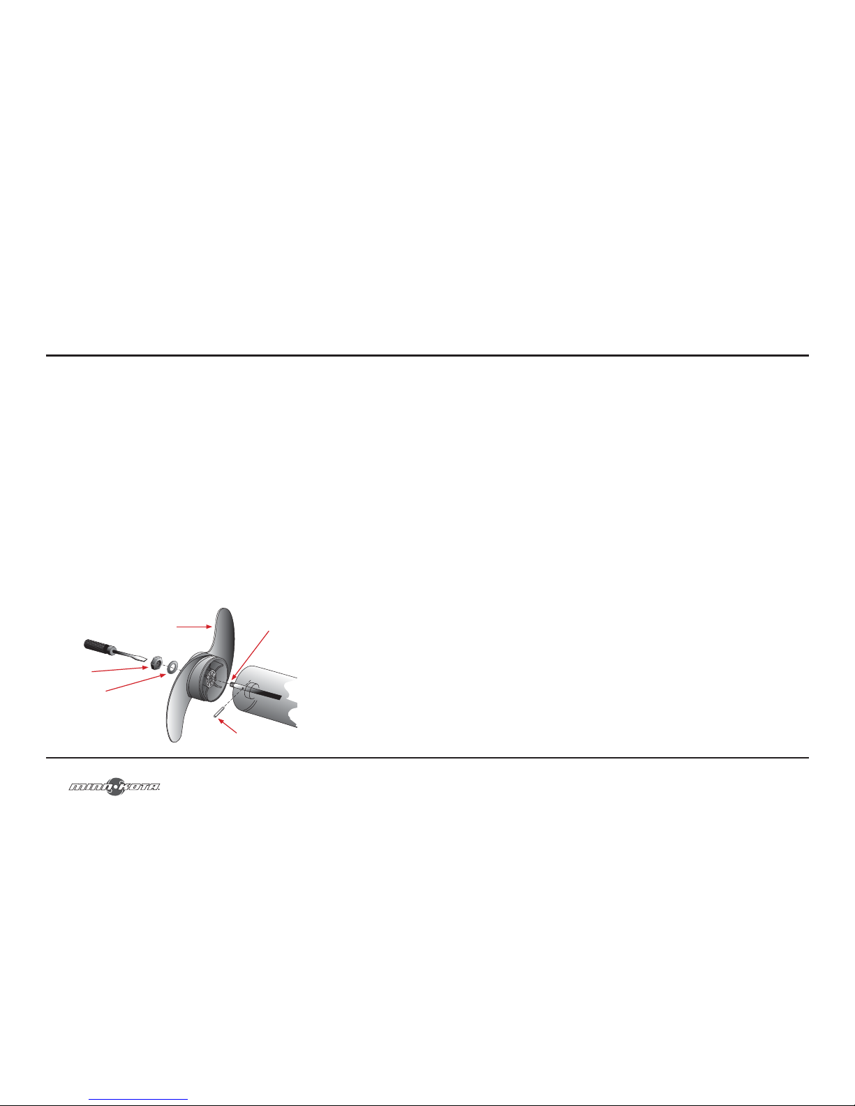
Propeller Replacement
!CAUTION!: DISCONNECT THE MOTOR FROM THE BATTERY BEFORE
BEGINNING ANY PROP WORK OR MAINTENANCE.
1. Disconnect the motor from all sources of power prior to changing the propeller.
2. Hold the propeller and loosen the anode/nut with a wrench.
3. Remove the anode/nut and washer. If the drive pin is sheared or broken, you
will need to hold the shaft steady with a blade screwdriver pressed into the slot
on the end of the shaft.
4. Turn the old prop to horizontal (as illustrated) and pull it straight off. If drive pin
falls out, push it back in.
5. Align the new propeller with the drive pin.
6. Install the prop washer and anode/nut.
7. Tighten the anode/nut ¼ turn past snug [25-35 inch lbs.] Do not over tighten
as this can damage the prop.
Weedless Propeller
Prop Nut
Washer
Drive Pin
Slot End
minnkotamotors.com
47
1. Il n’y a pas plus de 3 conducteurs qui sont regroupés à l’intérieur d’une gaine
ou d’un conduit qui se trouve en dehors des espaces allouées au moteur.
2. Chaque conducteur est muni d’un isolant d’une température nominale de 105° C.
3. Pas plus de 5 % de chute de tension n’est autorisée lorsque le moteur roule à
pleine puissance, en se basant sur les exigences d’alimentation du produit qui
ont été publiées.
Référence : Le code des règlements fédéraux des États-Unis (CFR) : 33 CFR 183 –
bateaux et équipements associés
ABYC E-11 : Systèmes électriques de CA et CC sur les bateaux
Sélectionner la batterie adéquate
Le moteur fonctionnera avec n’importe quelle batterie marine à décharge profonde
de 12 volts. Pour de meilleurs résultats, utilisez une batterie marine à décharge
profonde avec un ampérage nominal d’au moins 115 ampères/heure. Selon une
estimation générale effectuée sur l’eau, votre moteur de 12 volts utilisera un ampère
par heure et votre moteur de 24 volts, 0,75 ampère par heure, pour chaque coup
de poussée produite lorsque le moteur tourne à haute vitesse. L’ampérage réel
utilisé dépend de vos conditions environnementales spécifiques et des exigences de
fonctionnement. Maintenez la batterie complètement chargée. Un entretien adéquat
fera en sorte que vous ayez du courant venant de la batterie lorsque vous en aurez
besoin, et d’améliorer considérablement la vie de la batterie. Le fait de ne pas
recharger les batteries au plomb (dans les 12-24 heures) est la principale cause de
défaillance prématurée des batteries. Utilisez un chargeur à taux variable afin d’éviter
une surcharge. Si vous utilisez une batterie à manivelle pour démarrer un moteur
hors-bord à essence, nous vous recommandons d’utiliser une ou des batteries
marines à décharge profonde séparées pour votre moteur de pêche à la traîne Minn
Kota™.
Page 23
46
Gréage du bateau et installation du produit:
Pour des raisons de sécurité et de conformité, nous vous recommandons de suivre les
normes de l’American Boat and Yacht Council (ABYC) lors du gréage de votre bateau.
Les altérations dans le câblage du bateau devraient être complétées par un technicien
maritime qualifié. Les spécifications suivantes sont seulement des directives générales :
ATTENTION! : Ces directives s’appliquent au gréage général effectué afin de
supporter votre moteur de Minn Kota™. L’alimentation de multiples moteurs ou
d’autres appareils électriques, à partir du même circuit d’alimentation, peut influer
sur le gabarit de conducteurs et la taille de disjoncteur recommandée. Si vous utilisez
un fil plus long que celui fourni avec votre appareil, suivez les dimensions de gabarits
des conducteurs et des disjoncteurs qui se trouvent dans le tableau ci-dessous. Si la
longueur totale de votre conducteur est de plus de 15,24 mètres (50 feet), nous vous
recommandons de contacter un technicien maritime qualifié.
Un dispositif de protection contre les surintensités (disjoncteur ou fusible) doit être
utilisé. Les exigences de la garde côtière exigent que chaque conducteur de courant,
qui n’est pas fixé, soit protégé par une fusible ou un disjoncteur qui se réinitialise
manuellement et qui ne peut se déclencher automatiquement. Les dimensions du type
(courant et tension nominale) de fusible ou disjoncteur doivent être choisies en fonction
du moteur de pêche à la traîne utilisé. Le tableau ci-dessous donne les directives
recommandées pour ce qui est des dimensions des disjoncteurs.
Tableau des dimensions de gabarit des conducteurs et disjoncteurs
Longueur totale du conducteur (longueur de tous les conducteurs dans le circuit au complet)
Poussée du
moteur
Disjoncteur 3,05 mètres
(10 feet)
6,10 mètres
(20 feet)
9,14 mètres
(30 feet)
12,19 mètres
(40 feet)
15,24 mètres
(50 feet)
18,18 kg (40#),
20,46 kg (45#)
50 A à 12 VCC 10 AWG 8 AWG 6 AWG 4 AWG 4 AWG
22,72 kg (50#),
25 kg (55#)
60 A à 12 VCC 8 AWG 6 AWG 4 AWG 4 AWG 2 AWG
31,82 kg (70#) 50 A à 24 VCC 10 AWG 10 AWG 8 AWG 8 AWG 6 AWG
* Le tableau ci-dessus des dimensions de gabarit des conducteurs et disjoncteurs est uniquement valable pour les
hypothèses suivantes.
INSTALLATION DES BATTERIES ET DU CÂBLAGE
minnkotamotors.com
23
Maximizer™: (On Select Models)
The built-in Maximizer’s electronics create pulse with modulation to provide longer
running time and extended battery life. With the Maximizer speed control, you
may, in some applications, experience interference in your depth finder display. We
recommend that you use a separate deep cycle marine battery for your trolling motor
and that you power the depth finder from the starting / cranking battery. If problems
still persist, call our service department at 1-800-227-6433.
General Maintenance
1. After use, the entire motor should be rinsed with freshwater, then wiped down
with a cloth dampened with an aqueous based silicone spray such as Armor All
®
.
2. The propeller must be inspected and cleaned from weeds and fishing line after
every 20 hours of operation. Fishing line and weeds can get behind the prop,
damage the seals and allow water to enter the motor.
3. Verify the prop nut is secure each time the motor is used.
4. To prevent accidental damage during transportation or storage, disconnect the
battery whenever the motor is off of the water. For prolonged storage, lightly
coat all metal parts with an aqueous based silicone spray.
5. For maximum battery life recharge the battery(s) as soon as possible after use.
For maximum motor performance restore battery to full charge prior to use.
6. Keep battery terminals clean with fine sandpaper or emery cloth.
Page 24
24
SERVICE & MAINTENANCE
7. The weedless propeller is designed to provide absolute weed free operation
with very high efficiency. To maintain this top performance, the leading edge of
the blades must be kept smooth. If they are rough or nicked from use, restore
to smooth by sanding with fine sandpaper.
minnkotamotors.com
45
11. Fixez l’installation sur le pont du bateau en utilisant les boulons de 6,4 mm –
20 x 51 mm (1/4” – 20 X 2”), rondelles et écrous qui sont fournis. Ajustez
solidement, mais doucement l’équipement de support en acier inoxydable
au pont du bateau en utilisant une clé à œil de 11 mm (7/16”). Ajuster
l’équipement de support en acier inoxydable trop rapidement pourrait faire en
sorte que les boulons et écrous soient grippés et ou saisis.
12. Réinstallez le support du moteur en utilisant les six vis Phillips originales de 6,4
mm (1/4”).
13. Réinstallez l’assemblage du moteur dans le support et fixez solidement le
bouton de réglage de profondeur.
Page 25
44
INSTALLATION DU SUPPORT
8. Déterminez la structure du trou de montage que
vous souhaitez utiliser à partir de l’illustration
ci-dessous. En utilisant les trous de montage
dans le support comme modèle, marquez le
pont supérieur du bateau avec un crayon ou un
marqueur effaçable.
9. Retirez le support du pont du bateau et percez
les trous que vous avez marqués à l’étape
précédente en utilisant la perceuse et une
mèche de 7,144 mm (9/32”). Soyez prudent
afin de n’endommager aucun des câbles ou des
caractéristiques essentielles qui pourraient se
trouver sous la surface où vous allez percer.
10. Placez de nouveau le support sur le pont du
bateau et vérifiez que la bande Velcro™ est
installée et positionnée telle qu’indiquée.
40 cm
(15.75”)
minnkotamotors.com
25
Can I get replacement parts for my Minn Kota trolling motor?
Yes, we would be glad to help you with this. Please contact us for replacement parts
in the U.S.A. at 1 800 227 6433. In Canada, call 1 800 263 6390.
What about shaft length selection?
Choosing the correct shaft length is important so that the angler’s electric motor does
not cavitate, creating fish-spooking noise. The rule of thumb is that the center of the
motor section should be submerged 9". In general, shaft length selection is more critical
with bow-mount motors versus transom-mount motors. Most boat transoms are
similar in their distance to the water, and Minn Kota’s standard transom shaft lengths
should be adequate. With bow-mounted motors, there is much greater variation in
shaft length requirements. Measure down from the mounting surface of the transom
or bow to the water level. Add 5" to waterline measurement for fishing in rough water.
Add 12" to waterline measurement for steering a hand control motor while standing.
Use this measurement and the tables below to find the appropriate shaft length.
What are the benefits of a bow-mounted electric motor?
Boats do not tend to go in a straight line. Because of this, it is much easier to pull a boat
than to push a boat. It is also easier to move the bow of the boat sideways compared
to moving the transom. Therefore, a bow-mounted electric motor allows for much
greater boat control and positioning. If quick-response boat control and positioning is
what you are looking for, a Minn Kota bow-mount electric motor is a must.
FREQUENTLY ASKED QUESTIONS
Page 26
26
FREQUENTLY ASKED QUESTIONS
Will the CoPilot work with my cable steer or hand control
trolling motor?
No, CoPilot is designed only for electric steer motors.
minnkotamotors.com
43
5. Déployez le moteur et retirez l’assemblage du moteur du support en desserrant
le bouton de réglage de profondeur et en ouvrant la porte..
Bouton de réglage
de la profondeur
Assemblage
du moteur
AVERTISSEMENT! : Lorsque vous remontez ou abaissez le moteur, gardez vos
doigts loin de toutes charnières et points de pivot et de toutes pièces mobiles.
6. Positionnez de nouveau le support en position d’arrimage.
7. Retirez temporairement les vis Phillips, qui fixent le support du moteur au
moteur, et retirez le support du moteur afin d’exposer la structure du trou de
montage du moteur.
Page 27
42
INSTALLATION DU SUPPORT
2. Vérifiez que la zone sous l’emplacement choisi pour le montage est dégagée et
qu’il n’y a pas de danger pour percer.
3. Placez le moteur, en position d’arrimage, sur le dessus de l’emplacement de
montage désiré.
4. Vérifiez que le support du moteur est positionné assez loin au-dessus du bord
du bateau, afin que le moteur soit dégagé de tout obstacle lors du déploiement
et de l’arrimage du moteur.
minnkotamotors.com
27
1. Motor fails to run or lacks power:
• Check battery connections for proper polarity.
• Make sure terminals are clean and corrosion free. Use fine sandpaper
or emery cloth to clean terminals.
• Check battery water level. Add water if needed.
2. Motor loses power after a short running time:
• Check battery charge, if low, restore to full charge.
3. Motor is difficult to steer:
• Loosen the steering tension knob on the bracket.
• Lubricate the Composite Shaft.
4. You experience prop vibration during normal operation:
• Remove and rotate the prop 180°. See removal instructions in prop section.
NOTE: For all other malfunctions, see enclosed authorized service center listing for
nearest service center.
TROUBLESHOOTING
Page 28
28
This page provides Minn Kota
®
WEEE compliance disassembly
instructions. For more information about where you should dispose
of your waste equipment for recycling and recovery and/or your
European Union member state requirements, please contact your
dealer or distributor from which your product was purchased.
Tools required, but not limited to: Flat Head screw driver, Phillips
screw driver, socket set, pliers, wire cutters.
RIPTIDE SE 55/L&D
55 LBS THRUST
12 VOLT
52” SHAFT
PARTS DIAGRAM
208
200
205
210
210
400
395
220
225
245
235
215
410
260
255
230
390
360
365
370
375
380
385
420
240
250
415
405
522
265
500
520
minnkotamotors.com
41
Outils et ressources nécessaires :
• Tournevis Phillips
• Perceuse
• Mèche de 7,144 mm (9/32”)
• Clé à œil de 11 mm (7/16”)
• Une deuxième personne pour vous aider avec l’installation
1. Avant de procéder, déterminez l’emplacement désiré pour le montage du
moteur. Nous recommandons que le moteur soit monté aussi près que possible
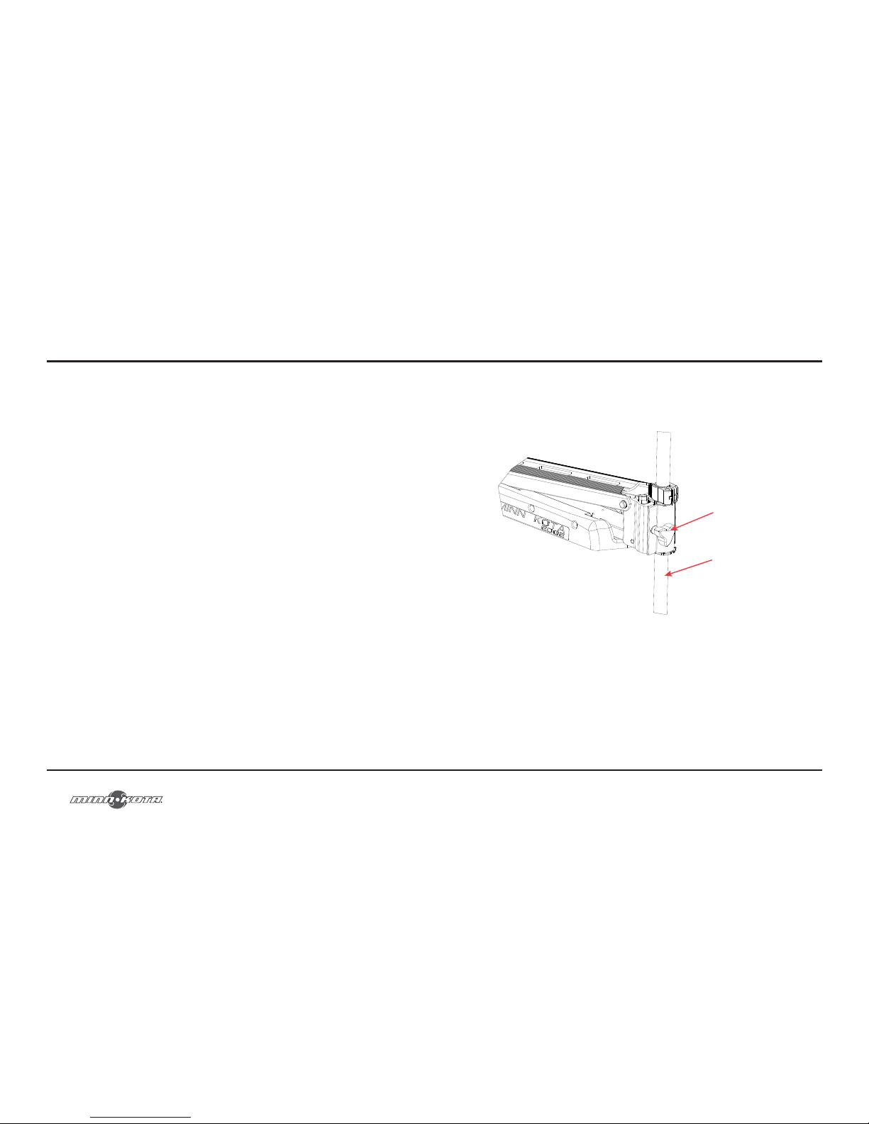
de l’axe des bateaux tel qu’illustré ci-dessous.
ATTENTION! : Assurez-vous que le moteur est monté sur une surface plane.
INSTALLATION DU SUPPORT
Page 29
40
CARACTÉRISTIQUES
Les spécifications sont sujettes à changement sans préavis.
Poignée de la Tilt Twist Tiller™
Bague de
profondeur réglable
Bouton d’alimentation
du gouvernail
Support de montage
Manche en composite
flexible garantie à vie
Hélice
Moteur Permanent Magnet,
Cool Power™
minnkotamotors.com
29
286
570
575
580
590
585
275
290
295
270
310
135
136
425
285
280
5
10
85
15
100
35
40
80
90
1010
75
50
55
60
1
70
20
95
30
45
25
1000
1015
1020
65
530
595
700
505
515
545
610
510
520
525
535
540
550
605
900
615
550
560
625
701
703
296
Page 30
30
ITEM # QTY PART NUMBER DESCRIPTION
1 1 2097095 12V MOTOR 52” SW
5 1 2-100-121 ARMATURE ASSEMBLY
10 1 140-010 BEARING
15 1 788-015 RETAINING RING
20 1 2-200-301 CENTER HOUSING ASSEMBLY
25 1 421-336 BRUSH END HOUSING ASSEMBLY
30 1 2-400-337 PLAIN END HOUSING ASSEMBLY
35 1 144-049 FLANGE BEARING
40 1 880-003 SEAL
45 1 880-006 SEAL WITH SHIELD
50 2 188-036 BRUSH
55 1 725-050 PAPER TUBE
60 1 738-036 BRUSH PLATE ASSEMBLY
65 2 975-040 BRUSH SPRING
70 1 337-036 GASKET
75 1 701-081 O-RING, MOTOR
80 2 701-008 O-RING, THRU-BOLT
85 2 830-007 SCREW, 8-32
90 2 830-042 THRU-BOLT
95 2 990-067 WASHER, STEEL
100 2 990-070 WASHER, NYLATRON
135 1 640-008 LEADWIRE, BLACK
136 1 640-107 LEADWIRE, RED
2888460 SEAL AND O-RING KIT
200 1 2065654 DECAL, C-BOX COVER
205 1 2060296 C-BOX COVER
208 2 2325666 DECAL - MINN KOTA
210 1 2074080 BATTERY METER, 12V SW
215 2 30 43427 SCREW, #8 X 7/8 SS
220 1 2184006 CONTROL BOARD, 12V
225 2 2303434 SCREW, #8-30 X 5/8 SS
230 1 2062503 CONTROL BOX VARS, SW
235 1 2062905 STRAIN RELIEF
240 6 2303412 SCREW, #6 X 5/8 SS
245 2 2263434 SCREW, #8 X 1 SS
250 1 2383407 SCREW, #10-24 X 2 SS
255 1 2061517 COLLAR, C-BOX
260 1 2383124 NUT, 10-24, NYLOCK, SS
265 1 2991521 CAM LOCK/DEPTH COLLAR ASSY
270 2 2261537 HINGE SLEEVE
1 2991839 HINGE & DOOR ASSEMBLY [275-295]
275 1 2261894 HINGE BASE ASSEMBLY
280 1 2261898 HINGE DOOR
285 2 2332100 SCREW, 8-32 X 3/8, SS
PARTS LIST
minnkotamotors.com
Caractéristiques ...................................................................40
Installation du support .........................................................41
Installation de la batterie et du câblage ................................46
Schéma du câblage menant au moteur ..................................50
Utilisation de votre Riptide SE ..............................................52
Fonctionnement de la poignée d’inclinaison et d’extension ....54
Ajuster la profondeur du moteur ..........................................56
Service et entretien ..............................................................58
Foire Aux Questions ............................................................61
Dépannage ...........................................................................63
Garantie ..............................................................................64
Déclaration de conformité ....................................................66
TABLE DES MATIÈRES
Page 31
Modèle : ____________________________________________________________
Numéro de série : _____________________________________________________
Date de l’achat : _______________________________________________________
Magasin où l’achat a été effectué : _________________________________________
REMARQUE : Ne retournez pas votre moteur Minn Kota à votre détaillant. Votre détaillant n’est pas
autorisé à réparer ou remplacer cette unité. Vous pouvez obtenir le service en : appelant Minn Kota au
1-800-227-6433; retournant votre moteur au Centre de service de la manufacture Minn Kota, envoyant
ou en emmenant votre moteur à un centre de service agréé de Minn Kota se trouvant sur la liste jointe.
Pour les services de garantie incluant toutes les options mentionnées ci-dessus, veuillez inclure la preuve
d’achat, numéro de série et date de l’achat.
Veuillez lire attentivement ce manuel de l’utilisateur. Suivez toutes les instructions et tenez compte de
toutes les consignes de sécurité et de mise en garde ci-dessous. L’utilisation de ce moteur n’est autorisée
que pour les personnes qui ont lu et compris ces instructions pour l’utilisateur. Les mineurs peuvent
utiliser ce moteur uniquement sous la supervision d’un adulte.
ATTENTION : Ne faites jamais fonctionner le moteur hors de l’eau, puisque cela pourrait entraîner des
blessures causées par le fait que l’hélice est en rotation. Raccordez le moteur à la batterie uniquement
si le moteur est en position de fonctionnement et le contrôle de vitesse en position zéro. Avant de faire
basculer le moteur vers le haut et de sortir les hélices hors de l’eau, débranchez le moteur de la source
d’alimentation. Lorsque vous branchez les câbles d’alimentation du moteur à la batterie, veillez à ce
qu’ils ne soient pas entortillés ou exposés au frottement et placez-les de telle manière que les personnes
ne puissent pas trébucher dessus. Avant d’utiliser le moteur, assurez-vous que l’isolant des câbles
d’alimentation n’est pas endommagé. Ne pas tenir compte de ces mesures de sécurité peut entraîner
des courts-circuits avec la ou les batteries et / ou le moteur. Débranchez toujours le moteur de la ou des
batteries avant le nettoyage ou la vérification de l’hélice. Évitez de submerger complètement le moteur,
car l’eau pourrait pénétrer dans l’unité inférieure par la tête et le manche de contrôle. Si le moteur est
utilisé, alors que de l’eau est présente dans l’unité inférieure, un court-circuit se produira et cela aura
pour conséquence d’endommager considérablement le moteur. Ces dommages ne seront pas couverts
par la garantie.
ATTENTION : Veillez à ce que ni vous, ni les autres personnes ne s’approchent trop près de l’hélice
en rotation, que ce soit seulement avec une partie du corps ou des objets. Le moteur est puissant et
pourrait provoquer des situations périlleuses ou des blessures, pour vous ou les autres. Lorsque le
moteur est en marche, méfiez-vous des objets flottants ou des personnes qui pourraient être en train
de nager. Les personnes, dont les réactions ou la capacité à faire fonctionner le moteur est affaiblie par
l’alcool, la drogue, les médicaments ou d’autres substances, ne sont pas autorisés à utiliser ce moteur.
Ce moteur n’est pas adapté à l’utilisation dans de forts courants. Le niveau de pression sonore constant
du moteur lors de l’utilisation est inférieure à 70 dB (A). Le niveau de vibration globale ne dépasse pas
2,5 m / sec2.
minnkotamotors.com
31
ITEM # QTY PART NUMBER DESCRIPTION
286 2 2261732 WASHER, #8 NYLON
290 1 2260906 KNOB
295 1 2261728 WASHER, RETAINING
310 1 2002014 TUBE COMPOSITE 52”
1 2990957 HANDLE ASSY, VARS [360-410]
360 1 2990456 GRIP/HANDLE ASSY, 5SPD [360-375]
365 2 2060015 BEARING, HANDLE
370 1 2063405 SCREW, #6 PFH SS
375 1 2884092 YOKE / SPIDER ASSY, VARS
380 1 2302742 SPRING, DETENT, OFF
385 2 2060005 BEARING, HANDLE PIVOT
390 1 2060900 HANDLE PIVOT, TOP
395 1 2302745 SPRING, RELEASE BUTTON
400 1 2063700 BUTTON, RELEASE
405 1 2060905 HANDLE PIVOT, BOTTOM
410 6 2303412 SCREW, #6 X 5/8 SS
415 1 2062715 SPRING, HANDLE PIVOT
420 1 2061700 WASHER, POT HOLDER
425 1 2292523 LEADWIRE ASSY
1 2991718 MOUNT, ASSEMBLY SHORT SW
[270-295, 500-625]
500 1 2251601 ROPE
505 1 2150400 PULL GRIP
510 1 2151700 WASHER
515 1 2264271 ARM-UPPER, SHORT
520 1 2263506 BOLT, 3/8-16 X 4.25, SS
522 1 2262310 ROPE GUIDE
525 2 2267303 BUSHING, UPPER 3/8”
530 1 2263115 NUT, 3/8-16 SS
535 2 2263510 BOLT, SHOULDER
540 2 2267302 BUSHING, SS
545 1 2994343 ARM, LOWER, STD, SW
550 3 2260504 PIN, PIVOT SS
560 4 2266002 BUSING, NYLINER 3/8
1 2993811 LATCH STRAP ASSY [570-590]
570 1 2263605 L ATCH STRAP
575 2 2261902 LATCH BRACKET
580 1 2262709 SPRING, LATCH PIN, SS
585 2 2260502 LATCH PIN, SS
590 4 2268602 RIVET, 1/8 SS
595 1 2266503 BOWPLATE W/ INSERT, STD, SW
605 1 2261544 YOKE
610 1 2263906 MOTOR REST, STD, SW
615 6 2332104 SCREW, 1/4-20 X 5/8, SS
Page 32
32
ITEM # QTY PART NUMBER DESCRIPTION
625 2 2265668 DECAL, MOTOR REST
1 2994830 BAG ASSEMBLY
700 6 2263431 SCREW, 1/4-20 X 3 1/2” PPH, SS
701 6 2301720 WASHER, RUBBER MOUNTING
702 6 2261713 WASHER, 1/4 SS
703 6 2263101 NUT, 1/4-20 NYLOCK, SS
900 1 2263804 STRAP, HOLD DOWN
1378131 PROPELLER KIT WW2
2994875 PROPELLER BAG ASSY
1000 1 2091160 PROPELLER WW2
1010 1 2092600 DRIVE PIN, SMALL
1015 1 2151726 WASHER, PROP, SMALL
1020 1 2198400 NUT, NYLOCK, PROP, ANODE
PARTS LIST
P/N 2194959 Rev. B ECN 33333 8/11
RIPTIDE SE
MOTEUR DE PÊCHE À LA TRAÎNE MONTÉ
SUR L’ÉTRAVE
MANUEL D’UTILISATION DU MASTER CE
Page 33

THIS PAGE INTENTIOANLLY LEFT BLANK
minnkotamotors.com
33
LIMITED WARRANTY
Composite Shaft
Johnson Outdoors Marine Electronics, Inc. warrants to the original purchaser that the composite shaft of
the purchaser’s Minn Kota
®
trolling motor is free from defects in materials and workmanship appearing
within the original purchaser’s lifetime. Johnson Outdoors Marine Electronics, Inc. will provide a new shaft,
free of charge, to replace any composite shaft found to be defective more than two (2) years after the
date of purchase. Providing such a new shaft shall be the sole and exclusive liability of Johnson Outdoors
Marine Electronics, Inc. and the sole and exclusive remedy of the purchaser for breach of this warranty;
and purchaser shall be responsible for installing, or for the cost of labor to install, any new composite shaft
provided by Johnson Outdoors Marine Electronics, Inc.
Entire Product
Johnson Outdoors Marine Electronics, Inc. warrants to the original purchaser that the purchaser’s entire
Minn Kota
®
trolling motor is free from defects in materials and workmanship appearing within two (2)
years after the date of purchase. Johnson Outdoors Marine Electronics, Inc. will, at its option, either repair
or replace, free of charge, any parts, including any composite shaft, found to be defective during the term
of this warranty. Such repair or replacement shall be the sole and exclusive liability of Johnson Outdoors
Marine Electronics, Inc. and the sole and exclusive remedy of the purchaser for breach of this warranty.
Terms Applicable to Both Warranties
These limited warranties do not apply to motors used commercially or in salt water, nor do they cover
normal wear and tear, blemishes that do not affect the operation of the motor, or damage caused by
accidents, abuse, alteration, modification, misuse or improper care or maintenance. DAMAGE TO
MOTORS CAUSED BY THE USE OF REPLACEMENT PROPELLERS OR OTHER REPLACEMENT PARTS
NOT MEETING THE DESIGN SPECIFICATIONS OF THE ORIGINAL PROPELLER AND PARTS WILL
NOT BE COVERED BY THIS LIMITED WARRANTY. The cost of normal maintenance or replacement
parts which are not defective are the responsibility of the purchaser. To obtain warranty service in the U.S.,
the motor or part believed to be defective, and proof of original purchase (including the date of purchase),
must be presented to a Minn Kota
®
Authorized Service Center or to Minn Kota®’s factory service center
in Mankato, MN. Any charges incurred for service calls, transportation or shipping/freight to/from the
Minn Kota
®
Authorized Service Center or factory, labor to haul out, remove, re-install or re-rig products
removed for warranty service, or any other similar items are the sole and exclusive responsibility of the
purchaser. Motors purchased outside of the U.S. (or parts of such motors) must be returned prepaid
Page 34
34
with proof of purchase (including the date of purchase and serial number) to any Authorized Minn Kota®
Service Center in the country of purchase. Warranty service can be arranged by contacting a Minn Kota®
Authorized Service Center listed on the enclosed sheet, or by contacting the factory at 1-800- 227-6433 or
fax 1-800-527-4464. Note: Do not return your Minn Kota
®
motor or parts to your retailer. Your retailer is
not authorized to repair or replace them.
THERE ARE NO EXPRESS WARRANTIES OTHER THAN THESE LIMITED WARRANTIES. IN
NO EVENT SHALL ANY IMPLIED WARRANTIES (EXCEPT ON THE COMPOSITE SHAFT),
INCLUDING ANY IMPLIED WARRANTIES OF MERCHANTABILITY OR FITNESS FOR
PARTICULAR PURPOSE, EXTEND BEYOND TWO YEARS FROM THE DATE OF PURCHASE.
IN NO EVENT SHALL JOHNSON OUTDOORS MARINE ELECTRONICS, INC. BE LIABLE FOR
INCIDENTAL, CONSEQUENTIAL OR SPECIAL DAMAGES.
Some states do not allow limitations on how long an implied warranty lasts or the exclusion or limitation
of incidental or consequential damages, so the above limitations and/or exclusions may not apply to
you. This warranty gives you specific legal rights and you may also have other legal rights which vary
from state to state.
minnkotamotors.com
35
ENVIRONMENTAL COMPLIANCE STATEMENT
It is the intention of Johnson Outdoors Inc. to be a responsible corporate citizen, operating in compliance
with known and applicable environmental regulations, and a good neighbor in the communities where we
make or sell our products.
WEEE Directive:
EU Directive 2002/96/EC “Waste of Electrical and Electronic Equipment Directive (WEEE)” impacts
most distributors, sellers, and manufacturers of consumer electronics in the European Union. The WEEE
Directive requires the producer of consumer electronics to take responsibility for the management of
waste from their products to achieve environmentally responsible disposal during the product life cycle.
WEEE compliance may not be required in your location for electrical & electronic equipment (EEE), nor
may it be required for EEE designed and intended as fixed or temporary installation in transportation
vehicles such as automobiles, aircraft, and boats. In some European Union member states, these vehicles
are considered outside of the scope of the Directive, and EEE for those applications can be considered
excluded from the WEEE Directive requirement.
This symbol (WEEE wheelie bin) on product indicates the product must not be
disposed of with other household refuse. It must be disposed of and collected
for recycling and recovery of waste EEE. Johnson Outdoors Inc. will mark all
EEE products in accordance with the WEEE Directive. It is our goal to comply in
the collection, treatment, recovery, and environmentally sound disposal of those
products; however, these requirement do vary within European Union member
states. For more information about where you should dispose of your waste
equipment for recycling and recovery and/or your European Union member state
requirements, please contact your dealer or distributor from which your product was purchased.
Disposal:
Minn Kota motors are not subject to the disposal regulations EAG-VO (electric devices directive) that
implements the WEEE directive. Nevertheless never dispose of your Minn Kota motor in a garbage bin but
at the proper place of collection of your local town council.
Never dispose of battery in a garbage bin. Comply with the disposal directions of the manufacturer or his
representative and dispose of them at the proper place of collection of your local town council.
 Loading...