

MINN KOTA PowerDrive 55, PowerDrive 70, PowerDrive 45, PowerDrive 50 Owner's Manual
POWERDRIVE
BOW-MOUNT TROLLING MOTOR
OWNER'S MANUAL
INTRODUCTION
Made by Minn Kota
Johnson Outdoors
POWERDRIVE 55/IP-54"_BT
MODEL 1358744
SER NO R365 MK12345
THANK YOU
ank you for choosing Minn Kota. We believe that you should spend more time fishing and less time positioning your boat.
Th
That’s why we build the smartest, toughest, most intuitive trolling motors on the water. Every aspect of a Minn Kota trolling
motor is thought out and rethought until it’s good enough to bear our name. Countless hours of research and testing provide you
the Minn Kota advantage that can truly take you “Anywhere. Anytime.” We don’t believe in shortcuts. We are Minn Kota. And we
are never done helping you catch more fish.
REGISTRATION
Re
member to keep your receipt and immediately register
your trolling motor. A registration card is included with
your motor or you can complete registration on our
website.
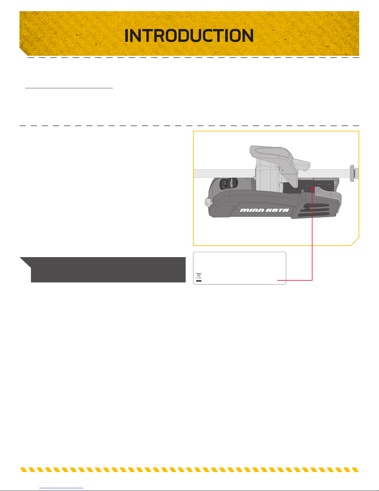
SERIAL NUMBER
Your Minn Kota 11-character serial number is very
important. It helps to determine the specific model and
year of manufacture. When contacting Consumer Service
or registering your product, you will need to know your
product’s serial number. We recommend that you write the
serial number down so that you have it available for future
reference.
NOTE: The serial number on your PowerDrive is
located inside the mount below the motor rests.
EXAMPLE
SAFETY CONSIDERATIONS
Please thoroughly read the user manual. Follow all instructions and heed all safety and cautionary notices. Use of this motor is
only permitted for persons that have read and understood these user instructions. Minors may use this motor only under adult
supervision.
WARNING
You are responsible for the safe and prudent operation of your vessel. We have designed your Minn Kota product to be an
accurate and reliable tool that will enhance boat operation and improve your ability to catch fish. This product does not relieve
you from the responsibility for safe operation of your boat. You must avoid hazards to navigation and always maintain a
permanent watch so you can respond to situations as they develop. You must always be prepared to regain manual control of
your boat. Learn to operate your Minn Kota product in an area free from hazards and obstacles.
WARNING
Never run the motor out of the water, as this may result in injuries from the rotating propeller. The motor should be disconnected
from the power source when it is not in use or is off the water. When connecting the power-supply cables of the motor to the
battery, ensure that they are not kinked or subject to chafe and route them in such a way that persons cannot trip over them.
Before using the motor make sure that the insulation of the power cables is not damaged. Disregarding these safety precautions
may result in electric shorts of battery(s) and/or motor. Always disconnect motor from battery(s) before cleaning or checking
the propeller. Avoid submerging the complete motor as water may enter the lower unit through control head and shaft. If the
motor is used while water is present in the lower unit considerable damage to the motor can occur. This damage will not be
covered by warranty.
WARNING
Take care that neither you nor other persons approach the turning propeller too closely, neither with body parts nor with objects.
The motor is powerful and may endanger or injure you or others. While the motor is running watch out for persons swimming
and for floating objects. Persons whose ability to run the motor or whose reactions are impaired by alcohol, drugs, medication,
or other substances are not permitted to use this motor. This motor is not suitable for use in strong currents. The constant noise
pressure level of the motor during use is less than 70dB(A). The overall vibration level does not exceed 2,5 m/sec2.
WARNING
When stowing or deploying the motor, keep fingers clear of all hinge and pivot points and all moving parts. In the event of
unexpected operation, remove power leads from the battery.
WARNING
It is recommended to only use Johnson Outdoors approved accessories with your Minn Kota motor. Using non-approved
accessories including to mount or control your motor may cause damage, unexpected motor operation and injury. Be sure to use
the product and approved accessories, including remotes, safely and in the manner directed to avoid accidental or unexpected
motor operation. Keep all factory installed parts in place including motor and accessory covers, enclosures and guards.
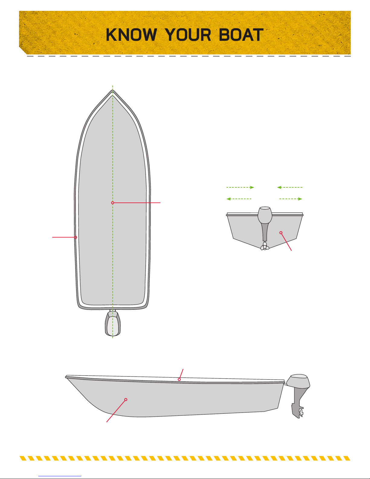
KNOW YOUR BOAT
Bow
Gunwale
Port
Starboard
Keel
Inboard
Outboard
Port Starboard
Transom
Stern
Bow
Hull
Gunwale
Stern
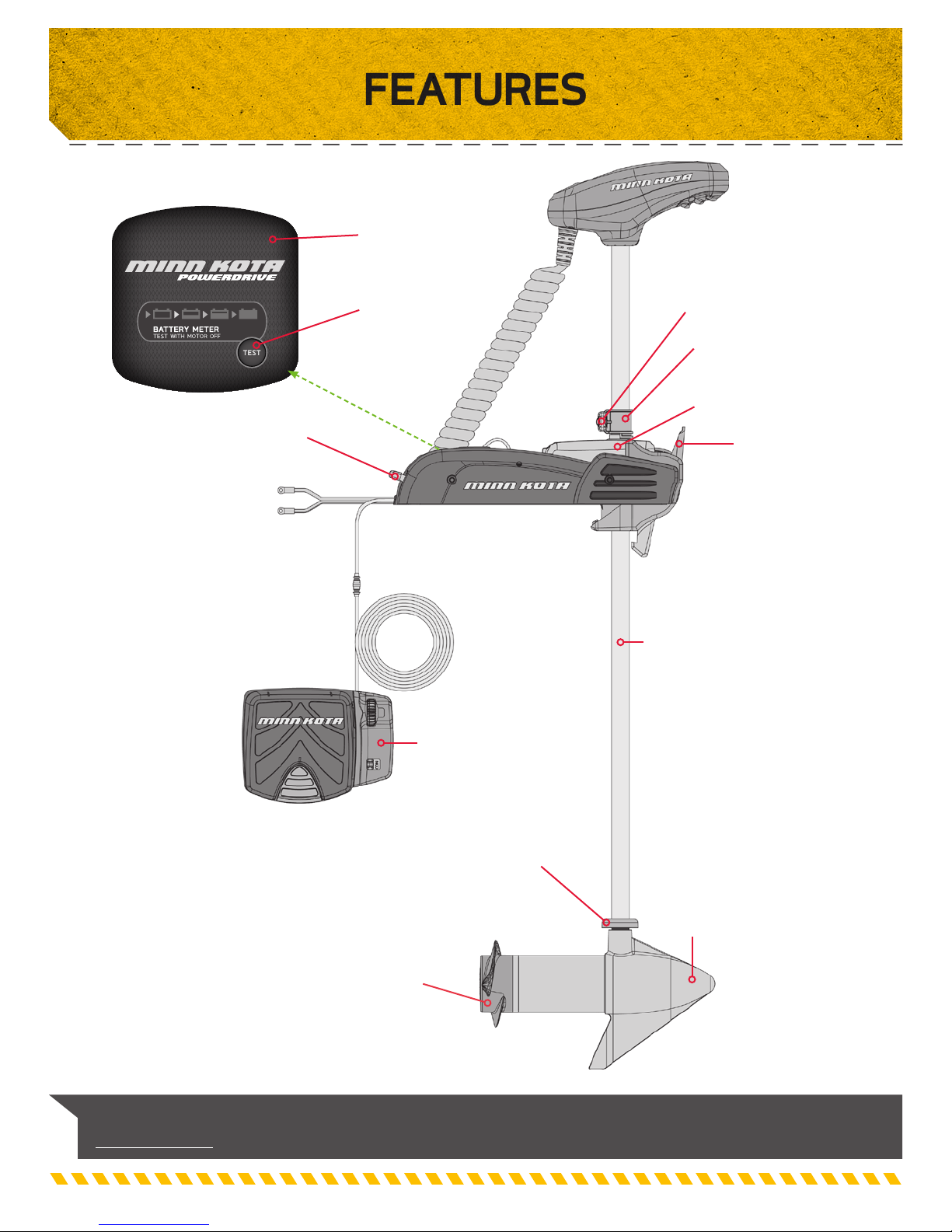
FEATURES
Indicator Panel
Tilt Lock Lever
Push-to-Test
Battery Meter
Low Profile
Foot Pedal
Depth Collar Knob
Adjustable Depth Collar
Steering Housing
Deploy-Assist Lever
Lifetime
Warranty Flexible
Composite Shaft
NOTE: Specifications subject to change without notice. This diagram is for reference only and may differ from
your actual motor.
Latch
Collar
Cool Quiet
Power Motor
Propeller
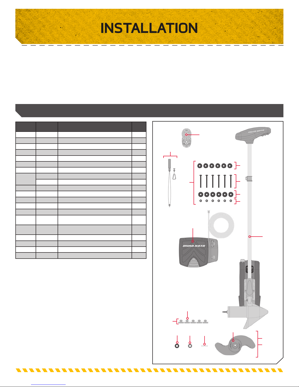
INSTALLATION
INSTALLING THE POWERDRIVE
ur new PowerDrive comes with everything you’ll need to directly install it to the boat. This motor can be directly mounted
Yo
to the boat or coupled with a Minn Kota quick release bracket for ease of mounting and removal. For installation with a
quick release bracket, refer to the installation instructions provided with the bracket. For compatible quick release mounting
brackets and to locate your nearest dealer. To install the motor directly to the boat, please follow the instructions provided in
this manual. Please review the parts list, mounting considerations and tools needed for installation prior to getting started. For
additional product support.
INSTALLATION PARTS LIST
Item /
Assembly
A
1
2
3
4
U
V
5
6
7
8
9
10
12
13
15 2397101 MANUAL, QUICK REF., iPILOT 1.6 1
16
Z 2994859
17
Part # Description Qty.
2994864
2263462 BOLT-MOUNTING-1/4X2 W/STG
2261713 WASHER-1/4
2263103 NUT NYLOK 1/4-20 MTG
2301720 WASHER-MOUNTING RUBBER
1378131 PROP IND 2091160 (WDLS WDGII)
1378121 PROP IND 2061122 (PWR PROP)
2091160 PROP-WW2 (3 5/8") REAMED SUB)
2061122 PROP-POWER (3.25")
2151726 WASHER-5/16 SS
2053101 NUT-PROP NYLOC
2092600 PIN-DRIVE 1.06" LG SS
2994727 FOOT PEDAL ASSEMBLY, PD
2390800
2994075
2317122
2325110
BAG SEMBLY - (BOLT, NUT, WHERS) 1
MOTOR ASSEMBLY
✖
LANYARD, REMOTE W/ CARABINER
t
REMOTE ASSEMBLY, IPILOT
t
MANUAL-INSTALL GUIDE, POWERDRIVE
BAG ASY-TERROVA/V2,RUB.BUMPERS
PAD, FOOT PEDAL PD
13
6
6
6
6
1
1
1
1
1
1
1
1
1
1
1
1
1
5
12
4
A
10
1
2
3
9
✖ This part is included in an assembly and cannot be ordered individually.
t Only available with models factory installed with i-Pilot.
17
Z
6 7 8
5
U
V
MOUNTING CONSIDERATIONS
is recommended that the motor be mounted as close to the centerline of the boat
It
as possible. Make sure the area under the mounting location is clear to drill holes and
install nuts and washers. Make sure the motor rest is positioned far enough beyond the
edge of the boat. The motor must not encounter any obstructions as it is lowered into
the water or raised into the boat when stowed and deployed. Consider a quick release
or adapter bracket with the installation of your motor.
TOOLS AND RESOURCES REQUIRED
INSTALLING THE POWERDRIVE
• #3 and #2 Phillips Screw Driver
• Drill
• 9/32” Drill Bit
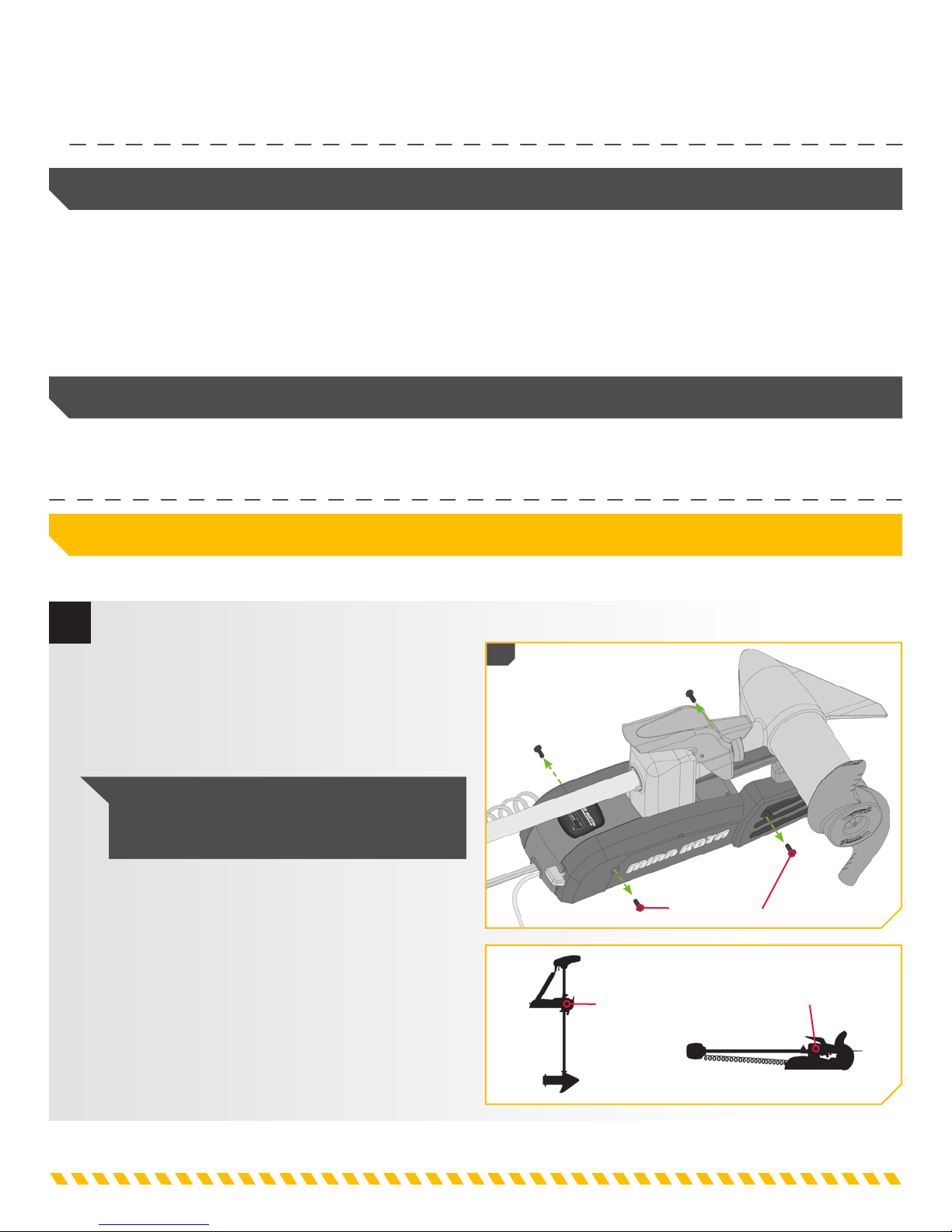
INSTALLATION
Installing the PowerDrive
1
a. Place the mount on an elevated, level surface
such as a workbench or the tailgate of a pickup.
The motor, as removed from the box, should be in
the stowed position.
b. Remove the four sideplate screws using a #3 or
#2 Phillips screwdriver. Two of these screws will
be located on each side of the mount.
NOTE: This motor weighs approximately
30 lbs. We recommend having a second person
help with the installation.
• 7/16” Box End Wrench
• A second person to help with the
installation
1b
Deployed
Sideplate Screw
Stowed
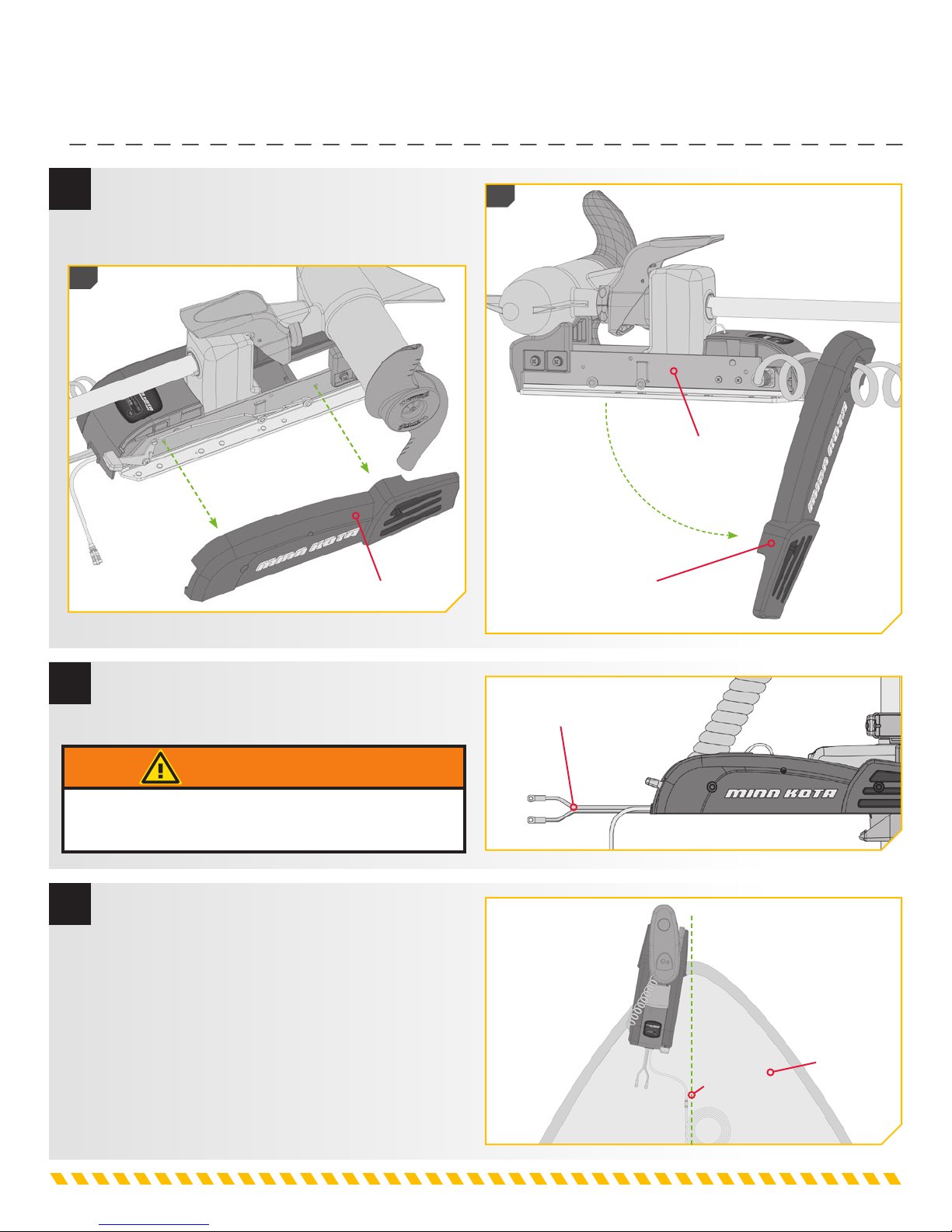
INSTALLING THE POWERDRIVE
2
c. Remove the Right Sideplate.
d. Swing the Left Sideplate out and away from the
Base Extrusion.
2c
Right Sideplate
2d
Base Extrusion
Left Sideplate
3
e. Make sure that the Power Cables from the
battery are disconnected, or that the breaker,
if equipped, is "off".
WARNING
Make sure the motor is mounted on a level surface and is
not connected to a power source.
4
f. Place the mount as close to the centerline or
keel of the boat as possible. The motor can
be installed on either the Port or Starboard
side of the boat based on personal preference.
placement with the motor in the stowed
Check
and deployed positions.
considerations at the beginning of the installation.
Review the mounting
Power Cables
Deck of Boat
Keel
INSTALLING THE POWERDRIVE
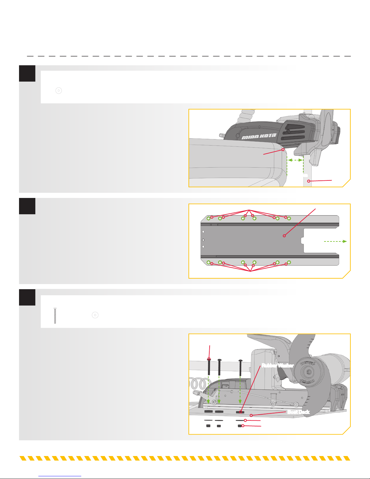
5
6
ITEM(S) NEEDED
#4 x 6
g. When the motor is in the deployed position, make
sure that the Shaft is 1-1/2" out past the Gunwale
of the boat. The lower unit, when stowed and
deployed must not encounter any obstructions.
h. Check to be sure that the mount is level. Use the
Rubber Washers (Item#4) provided to create a
level surface if necessary.
i. It is recommended to mark at least 6 of the
12 holes in the Base Extrusion and to have a
minimum of two bolts on each side that are
located the farthest apart. Ideal installation would
allow for 6 bolts to be used, with a minimum of 4.
Gunwale
Drilling Locations
1-1/2"
Minimum
Shaft
Base Extrusion
Bow
7
j. Drill through the deck of the boat using a 9/32"
Drill Bit on the marked locations.
ITEM(S) NEEDED
#1 x 6
k. Put a 1/4-20 x 3-1/2" (Item #1) screw in each
of the drilled locations. The screw should pass
through the Base Extrusion and the boat deck.
If the Rubber Washers (Item #4) are used, they
should sit between the Base Extrusion and boat
deck. Make sure to secure the motor with screws
on each side of the Base Extrusion.
#4 x 6
Drilling Locations
1/4-20 x 3 1/2" Screw
Rubber Washer
Boat Deck
Flat Washer
Nylock Nut

INSTALLING THE POWERDRIVE
8
9
ITEM(S) NEEDED
#2 x 6 #3 x 6
l. Place a Flat Washer (Item #2) and then a Nylock
Nut (Item #3) at the end of each screw as shown
and secure. Make sure all hardware is secure.
NOTE: To prevent seizing of the stainless steel
hardware, do not use high speed installation tools.
Wetting the screws or applying an anti-seize may
help prevent seizing.
m. Replace the Right Sideplate.
n. Swing the Left Sideplate back into its correct
position on the Base Extrusion.
1/4-20 x 3 1/2" Screw
Rubber Washer
Boat Deck
Flat Washer
Nylock Nut
9n
9m
Base Extrusion
Right Sideplate
Left Sideplate
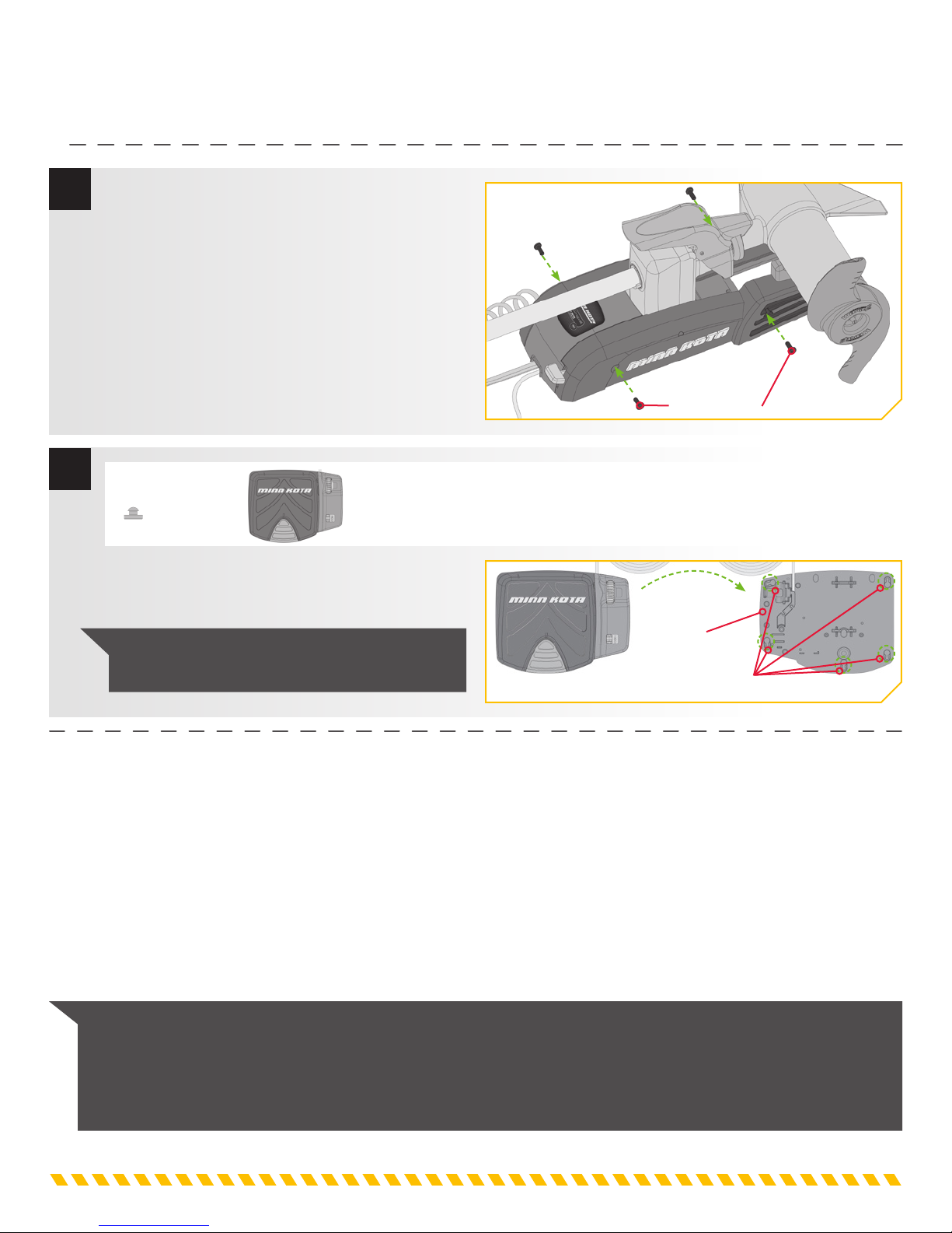
ROUTING UNIVERSAL SONAR
10
11
o. Replace the four sideplate screws using a #3 or
#2 Phillips screwdriver. Two of these screws will
be located on each side of the mount.
ITEM(S) NEEDED
#17 x 5 #10 x 1
p. Take the Foot Pedal (Item #10) and turn it over.
Put a Foot Pedal Pad (Item #17) in each of the
pad locations.
NOTE: The pads are recommended when using
the Foot Pedal on non-carpeted surfaces.
Sideplate Screw
Foot Pedal
Bottom
Foot Pedal
Pad Placement
Routing Universal Sonar
Your trolling motor may be pre-installed with a Universal Sonar transducer system. Universal Sonar is a 2D sonar transducer
with a temperature sensor that is integrated into the lower unit of the trolling motor. It has an operating frequency of 83/200
kHz. Connecting this transducer to a compatible fish finder* gives you a 2D sonar view of what is happening directly below your
trolling motor. The integrated design protects the transducer from underwater hazards, and prevents tangles and damage to the
transducer cables.
In certain situations, air bubbles may adhere to the surface of the Universal Sonar transducer, and effect the performance. If this
happens simply wipe the surface of the transducer with your finger.
All Universal Sonar motors are equipped with an internal bonding wire, incorrect rigging will cause sonar interference and can
damage your trolling motor, electronics and other boat accessories. Please refer to the Battery & Wiring Installation and Motor
Wiring Diagram sections of this manual for correct rigging instructions.
NOTE: Universal Sonar only provides 2D sonar that operates at 83/200 kHz. It does not support imaging screens that
require higher frequencies such as 455 kHz or 800 kHz (Down Imaging, Side Imaging, etc.). Down Imaging (DI) specific
units are not compatible with Universal Sonar. See compatibility chart for a list of compatible fish finders. *Requires an
adapter that is sold separately. For a current list of compatible fish finders and the correct adapter cable.
ROUTING UNIVERSAL SONAR
Your trolling motor may be pre-installed with a Universal Sonar transducer system. For compatibility and more information on
Universal Sonar, please. Your trolling motor may also be pre-installed with i-Pilot. To learn more about the GPS capabilities
available with your i-Pilot navigation system, please refer to the corresponding Owner's Manual.
Universal Sonar requires cables to be connected to an output device. This connection is present on the trolling motor inside the
Control Head. The i-Pilot system does not need an external wired connection. If a connection is present, it is to connect the
Universal Sonar. Please follow the Minn Kota recommendations on routing the cables to optimize mobility and maximize
functionality.
route cables.
The Universal Sonar Cables are shielded to minimize interference. To protect this shielding the cables should not be pulled tight
against sharp angles or hard objects. If using cable ties, do not over-tighten. Any excess cable should be bundled in a loose
loop of no less than 4” in diameter.
To minimize trolling motor interference, ensure that the fish finder and trolling motor are powered by separate batteries. Please
refer to the Battery & Wiring Installation and Motor Wiring Diagram sections of this manual for correct rigging instructions.
The routing will be the same regardless of the number of cables present. Use the following instructions to properly
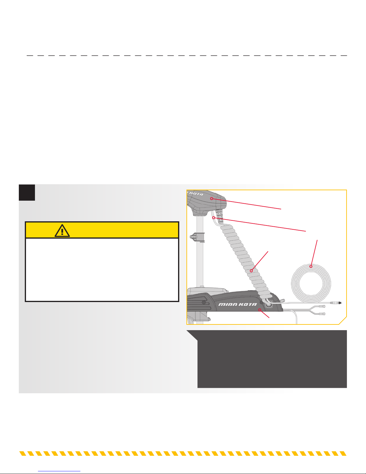
1
a. Place the motor in the stowed position.
b. Locate the Universal Sonar, at the base of the
Control Head.
UTION
Not following the recommended wire routing for the
Universal Sonar cables, if equipped, may cause damage to
the product and void your product warranty. Route cables
away from pinch points or other areas that may cause
them to bend in sharp angles. Routing the cables in any
way other than directed may cause damage to the cables
by being pinched or severed.
c. The Universal Sonar Cable should be fed all the
way through the Coil Cord. It should exit the
Coil Cord at the bottom of the Coil Cod, where it
connects to the Mount.
Control Head
Universal
Sonar
Coil Cord
Mount
NOTE: After the Universal Sonar Cable exits the
Coil Cord, it should be routed through an established
routing system on the boat, in an area with minimal
interference. Inspect the selected route carefully to
ensure that there are no sharp edges, obstacles, or
obstructions that may damage the cables.
CONNECTING A UNIVERSAL SONAR EXTENSION CABLE
Connecting a Universal Sonar Extension Cable
The Universal Sonar Cable may not be long enough to reach the fish finder. If the cable length does not reach the desired fish
finder installation location, a 14.5’ extension cable is available. Minn Kota recommends using the MKR-US2-11.
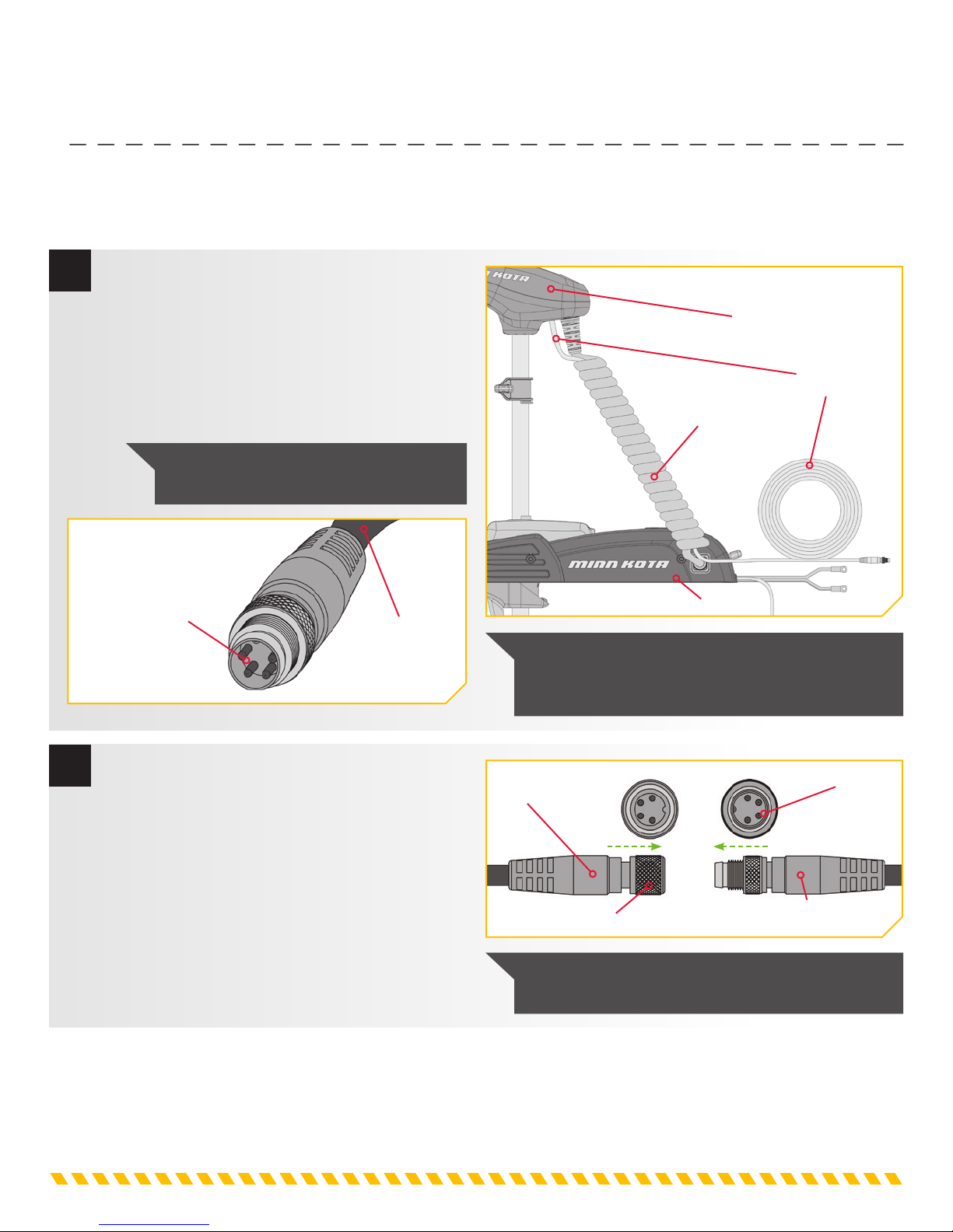
1
a. Place the motor in the stowed position.
b. Locate the Universal Sonar, if equipped, at the
c. Locate the Universal Sonar four pin connector at
Four Pin Connector
base of the Mount.
the end of Universal Sonar Extension Cable. The
connector is black with a stainless steel threaded
locking collar.
NOTE: Your fish finder should be turned
off until this procedure is complete.
Universal Sonar
Cable from
Control Head
Control Head
Universal
Sonar
Coil Cord
Mount
NOTE: If the cable length does not reach the desired
fish finder installation location, a 14.5’ extension cable
is available (MKR-US2-11) (sold separately).
2
d. Align the pins of the Universal Sonar connector
plug from the Control Head with the matching
socket end of the appropriate Universal Sonar
Extension Cable for your fish finder. Firmly
push the connector plug into the socket of the
Universal Sonar connection. Twist the locking
collar until it is snug.
e. Connect the other end of your adapter plug to
your fish finder following the manufacturer’s
instructions.
Universal Sonar
Extension Cable
Locking Collar
Four Pin Connector
Universal Sonar Cable
from Control Head
NOTE: The connectors are keyed to prevent reversed
installation.
BATTERY & WIRING INSTALLATION
BOAT RIGGING & PRODUCT INSTALLATION
For safety and compliance reasons, we recommend that you follow American Boat and Yacht Council (ABYC) standards when
rigging your boat. Altering boat wiring should be completed by a qualifi ed marine technician. The following specifi cations are for
general guidelines only:
UTION
These guidelines apply to general rigging to support your Minn Kota motor. Powering multiple motors or additional electrical devices from the
same power circuit may impact the recommended conductor gauge and circuit breaker size. If you are using wire longer than that provided with
your unit, follow the conductor gauge and circuit breaker sizing table below. If your wire extension length is more than 25 feet, we recommend
that you contact a qualifi ed marine technician.
UTION
An over-current protection device (circuit breaker or fuse) must be used. Coast Guard requirements dictate that each ungrounded
current-carrying conductor must be protected by a manually reset, trip-free circuit breaker or fuse. The type (voltage and current rating) of the
fuse or circuit breaker must be sized accordingly to the trolling motor used. The table below gives recommended guidelines for circuit breaker
sizing.
CONDUCTOR GAUGE AND CIRCUIT BREAKER SIZING TABLE
This conductor and circuit breaker sizing table is only valid for the following assumptions:
1. No more than 3 conductors are bundled together inside of a sheath or conduit outside of engine spaces.
2. Each conductor has 105° C temp rated insulation.
3. No more than 5% voltage drop allowed at full motor power based on published product power requirements.
Motor Thrust / Model Max Amp Draw Circuit Breaker
30 lb. 30
40 lb., 45 lb. 42 10 AWG 8 AWG 6 AWG 4 AWG 4 AWG
50 lb., 55 lb. 50 60 Amp @ 12 VDC 8 AWG 6 AWG 4 AWG 4 AWG 2 AWG
70 lb. 42 50 Amp @ 24 VDC 10 AWG 10 AWG 8 AWG 8 AWG 6 AWG
80 lb. 56 60 Amp @ 24 VDC 8 AWG 8 AWG 8 AWG 6 AWG 6 AWG
101 lb. 46 50 Amp @ 36 VDC 8 AWG 8 AWG 8 AWG 8 AWG 8 AWG
Engine Mount 101 50 60 Amp @ 36 VDC 8 AWG 6 AWG 4 AWG 4 AWG 2 AWG
112 lb. 52 60 Amp @ 36 VDC 8 AWG 8 AWG 8 AWG 8 AW G 8 AWG
Engine Mount 160 116 (2) x 60 Amp @ 24 VDC 2 AWG 2 AWG 2 AWG 2 AWG 2 AWG
E-Drive 40 50 Amp @ 48 VDC 10 AWG 10 AWG 10 AWG 10 AWG 10 AWG
NOTE: Wire Extension Length refers to the distance from the batteries to the trolling motor leads. Consult website for
available thrust options. Maximum Amp Draw values only occur intermittently during select conditions and should not be
used as continuous amp load ratings.
50 Amp @ 12 VDC
5 feet 10 feet 15 feet 20 feet 25 feet
10 AWG 10 AWG 8 AWG 6 AWG 4 AWG
Wire Extension Length
Reference
United States Code of Federal Regulations: 33 CFR 183 – Boats and Associated Equipment ABYC E-11: AC and DC Electrical Systems on
Boats
 Loading...