

MINN KOTA 1355975, Pontoon HC 70 User Manual
PONTOON HAND CONTROL
OW-MOUNT TROLLING MOTOR
B
USER MANUAL
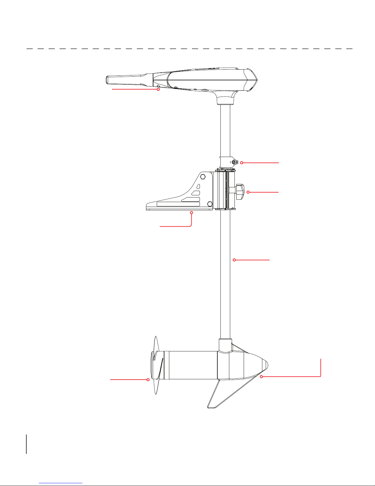
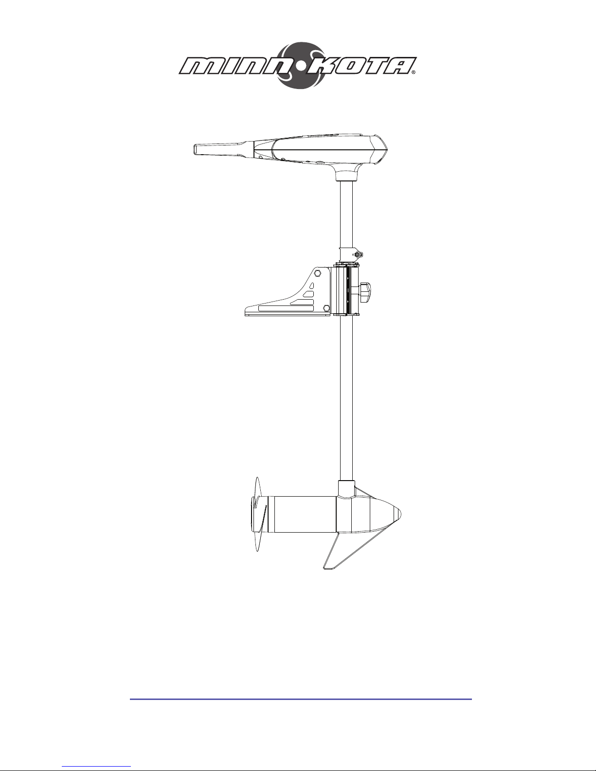
Tilt-Twist Handle Controls:
On/Off, Speed, Forward/
Reverse and Direction
FEATURES
Adjustable Depth Collar
Steering Tension Knob
Propeller
Mounting Bracket
Lifetime Warranty
Flexible Composite Shaft
Cool Quiet
Power Motor
Specifications subject to change without notice.
*This diagram is for reference only and may differ from your actual motor.
MOUNT INSTALLATION
TOOLS AND RESOURCES REQUIRED:
• Phillips Screw Driver
• Drill
• 9/32” Drill Bit
• 7/16” Box End Wrench
• A second person to help with the installation
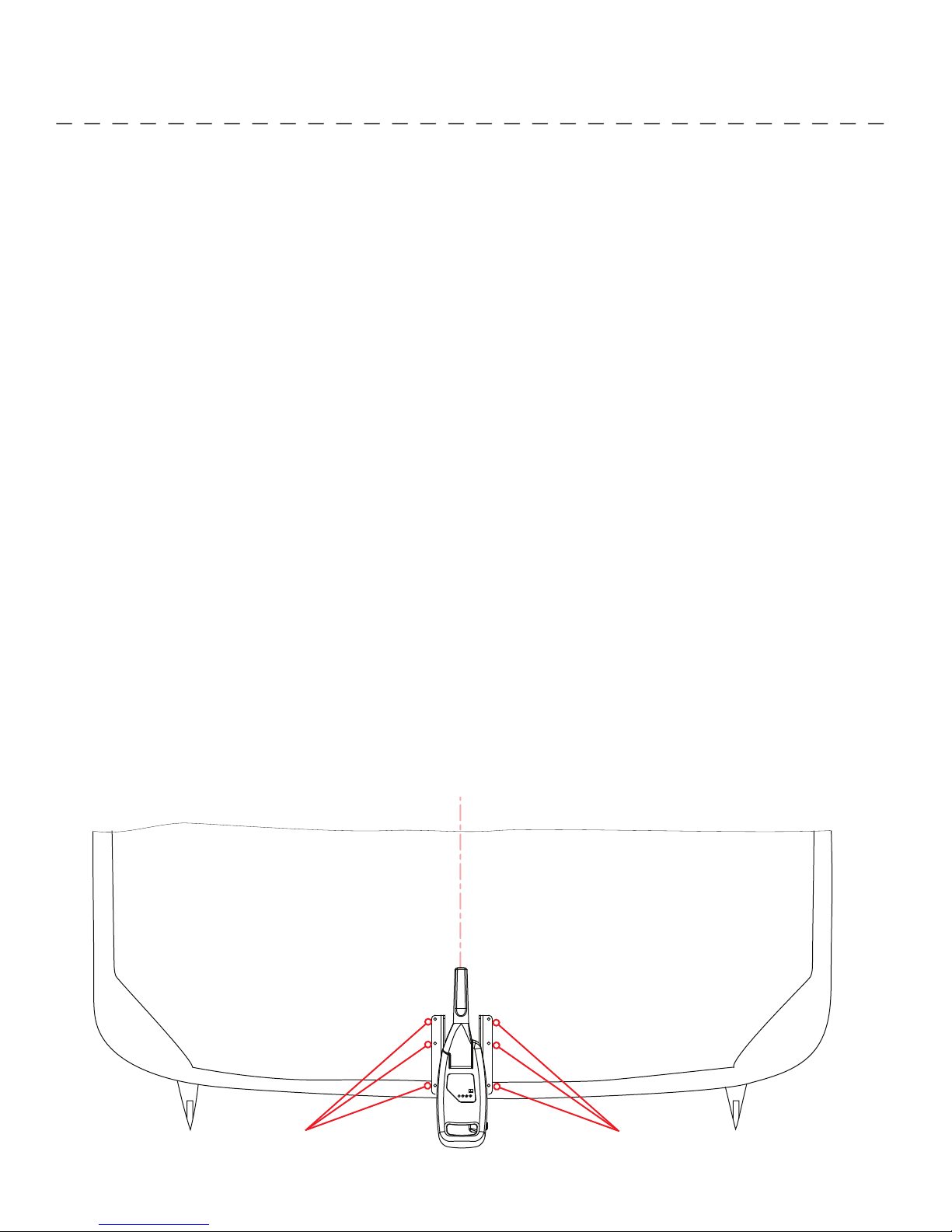
1. Before you proceed, determine the desired mounting location for the motor. It is recommended that the motor be mounted as
close to the center line of the boat as possible as seen below. Verify that there are no obstacles that the control box, handle,
or prop might hit while in use that would restrict steering or cause damage to the motor.
CAUTION: Make sure the motor is mounted on a level surface and is not connected to a power source.
2. Verify the area under the chosen mounting location is clear and safe to drill through.
3. Once in position, mark a minimum of four of the six mounting holes (two on each side). Drill through the marked holes using a
9/32 drill bit.
NOTE: The four front mounting holes uses the same bolt pattern as used on Minn Kota quick release plates MKA-21, RTA17, MKA-16-02 and MKA-32. The pontoon mount may be attached to any of these for your mounting convenience. Deploy
the motor and remove the motor assembly from the mount by loosening the Steering Tension Knob and opening the door.
4. Mount the plate to the bow through the drilled holes using the 1/4”-20 x 2” bolts, washers and nuts provided.
NOTE: When setting the depth be sure the top of the motor is submerged at least 12” to avoid churning or agitation of surface
water. The propeller must be completely submerged.
WARNING:
When raising or lowering motor, keep fi ngers clear of all hinge and pivot points and all moving parts.
Mounting Holes
(3 Per Side)
Mounting Holes
(3 Per Side)

BATTERY WIRING & INSTALLATION
BOAT RIGGING & PRODUCT INSTALLATION
For safety and compliance reasons, we recommend that you follow American Boat and Yacht Council (ABYC) standards when
rigging your boat. Altering boat wiring should be completed by a qualifi ed marine technician. The following specifi cations are for
general guidelines only:
CAUTION: These guidelines apply to general rigging to support your Minn Kota motor. Powering multiple motors or additional
electrical devices from the same power circuit may impact the recommended conductor gauge and circuit breaker size. If you are
using wire longer than that provided with your unit, follow the conductor gauge and circuit breaker sizing table below. If your wire
extension length is more than 25 feet, we recommend that you contact a qualifi ed marine technician.
An over-current protection device (circuit breaker or fuse) must be used. Coast Guard requirements dictate that
each ungrounded current-carrying conductor must be protected by a manually reset, trip-free circuit breaker or fuse. The type
(voltage and current rating) of the fuse or circuit breaker must be sized accordingly to the trolling motor used. The table below gives
recommended guidelines for circuit breaker sizing.
Reference:
United States Code of Federal Regulations: 33 CFR 183 – Boats and Associated Equipment
ABYC E-11: AC and DC Electrical Systems on Boats
CONDUCTOR GAUGE AND CIRCUIT BREAKER SIZING TABLE
Motor Thrust /
Model
30 lb. 30
40 lb., 45 lb. 42 10 AWG 8 AWG 6 AWG 4 AWG 4 AWG
50 lb., 55 lb. 50 60 Amp @ 12 VDC 8 AWG 6 AWG 4 AWG 4 AWG 2 AWG
70 lb. 42 50 Amp @ 24 VDC 10 AWG 10 AWG 8 AWG 8 AWG 6 AWG
80 lb. 56 60 Amp @ 24 VDC 8 AWG 8 AWG 8 AWG 6 AWG 6 AWG
101 lb. 46 50 Amp @ 36 VDC 8 AWG 8 AWG 8 AWG 8 AWG 8 AWG
Engine Mount 101 50 60 Amp @ 36 VDC 8 AWG 6 AWG 4 AWG 4 AWG 2 AWG
112 lb. 52 60 Amp @ 36 VDC 8 AWG 8 AWG 8 AWG 8 AWG 8 AWG
Engine Mount 160 116 (2) x 60 Amp @ 24 VDC 2 AWG 2 AWG 2 AWG 2 AWG 2 AWG
E-Drive 40 50 Amp @ 48 VDC 10 AWG 10 AWG 10 AWG 10 AWG 10 AWG
This conductor and circuit breaker sizing table is only valid for the following assumptions:
1. No more than 3 conductors are bundled together inside of a sheath or conduit outside of engine spaces.
2. Each conductor has 105° C temp rated insulation.
3. No more than 5% voltage drop allowed at full motor power based on published product power requirements.
*Wire Extension Length refers to the distance from the batteries to the trolling motor leads.
Max Amp Draw Circuit Breaker
5 feet 10 feet 15 feet 20 feet 25 feet
10 AWG 10 AWG 8 AWG 6 AWG 4 AWG
50 Amp @ 12 VDC
Wire Extension Length *

CONNECTING THE BATTERIES
BATTERY WIRING & INSTALLATION
SELECTING THE CORRECT BATTERIES
The motor will operate with any lead acid, deep cycle marine 12 volt battery/batteries. For best results, use a deep cycle, marine
battery with at least a 105 ampere hour rating. Maintain battery at full charge. Proper care will ensure having battery power
when you need it, and will signifi cantly improve the battery life. Failure to recharge lead-acid batteries (within 12-24 hours) is the
leading cause of premature battery failure. Use a multi-stage charger to avoid overcharging. We off er a wide selection of chargers
to fi t your charging needs. If you are using a crank battery to start a gasoline outboard, we recommend that you use a separate
deep cycle marine battery/batteries for your Minn Kota trolling motor.
Advice Regarding Batteries:
• Never connect the (+) and the (–) terminals of the same battery together. Take care that no metal object can fall onto the
battery and short the terminals. This would immediately lead to a short and extreme fi re danger.
• It is highly recommended that a circuit breaker or fuse be used with this trolling motor. Refer to “Conductor Gauge and Circuit
Breaker Sizing Table” in the previous section to fi nd the appropriate circuit breaker or fuse for your motor. For motors requiring
a 60-amp breaker, the Minn Kota MKR-19 60-amp circuit breaker is recommended.
12 VOLT SYSTEMS:
1. Make sure that the motor is switched off (speed selector on “OFF” or “0”).
2. Connect positive ( + ) red lead to positive ( + ) battery terminal.
3. Connect negative ( – ) black lead to negative ( – ) battery terminal.
4. For safety reasons do not switch the motor on until the propeller is in the water.
CAUTION:
For safety reasons, disconnect the motor from the battery/batteries when the motor is not in use or while the
battery/batteries are being charged.
CONNECTING THE BATTERIES IN SERIES (IF REQUIRED FOR YOUR MOTOR)
24 VOLT SYSTEMS:
1. Make sure that the motor is switched off (speed selector on “0”).
2. Two 12 volt batteries are required.
3. The batteries must be wired in series, only as directed in wiring
To trolling motor negative
24 Volt Connection
diagram, to provide 24 volts.
a. Connect a connector cable to the positive ( + ) terminal of
battery 1 and to the negative ( – ) terminal of battery 2.
Neg - Neg -Pos + Pos +
b. Connect positive ( + ) red motor lead to
positive ( + ) terminal on battery 2.
Battery #1 (Low Side)
c. Connect negative ( – ) black motor lead to
negative ( – ) terminal of battery 1.
24 Volt Series Connection
4. For safety reasons do not switch the motor on until the propeller is in the water. If installing a leadwire plug, observe proper
polarity and follow instructions in your boat owner’s manual. See wiring diagram on following pages.
CAUTION
• For safety reasons, disconnect the motor from the battery or batteries when the motor is not in use or while
the battery/batteries are being charged.
• Improper wiring of 24/36 volt systems could cause battery explosion!
• Keep leadwire wing nut connections tight and solid to battery terminals.
• Locate battery in a ventilated compartment.
+24 Volts to trolling motor
positive (or circuit breaker)
Battery #2 (High Side)
 Loading...