

Minka-Aire Riva, Riva F586 Instruction Manual
CERTIFICATE

This pr oduct is protect ed by Unite d States and/ or State Law, including Patent, Trad emark and/or Copyright la ws.
Manua l design is protec ted by Unit ed State Federal a nd/or State Law, includin g Patent. Trademark and/o r Copyright laws.
R
Minka -Aire warra nts to the origina l owner tha t this fan will be fre e from defects in material an d workmanship for one year
R
from th e date of purchase , excludi ng the motor. Mink a-Aire warra nts to the origina l owner tha t the motor in this fa n shall be free
from de fects in materia l and workm anship for as long a s the original purchaser ow ns the fan, and it remains in the o riginal
insta llation.
This is a l imited warrant y. Minka- Aire ’s only obligati on under this limited warra nty is to replace or r epair, or r efund the purcha se price, i n Minka-
R R
Aire ’s sole discretion with out charge to the original ow ner, of the fan once Minka-Ai re con firms that the fan has a defect c overed by this limited
R
Call ou r customer servi ce depart ment at 1-800-30 7-3267 to o btain the name of th e
conta ct us through our we b site, www .minkagroup. net and write to: Ask Mr.Mink a if you have any questions or re quire further assistanc e.
R
Minka -Aire authorized dealer clos est to your location, or
To obta in warranty serv ice, the ow ner should retur n the fan along with proof of pur chase to a
autho rized dealer sha ll then, at i ts sole discreti on: repai r the fan, replace t he fan,refund the purchas e price less the amount direc tly attributable to the
R R
consu mer’s prior usag e of the fan, o r if necessary ins truct the consumer to conta ct Minka-Aire directly for warranty se rvice. Minka-Aire will be
R
respo nsible for the cos t of any repa ir, or replaceme nt for any warranty service p rovided by a Minka-Aire author ized deal er for product und er warranty.
R R
Minka -Aire author ized dealer. The Minka-Ai re
You may a lso at your prefer ence obtain warranty serv ice by returning the fan dire ctly to
R
retur n address, and a des criptio n of the claimed pro duct defect. Pack careful ly; damage sustained in ret urn transit to Minka-Aire will b e the original
owner ’s responsibil ity. Orig inal owner shall b e responsible to pay all ship ping charges. To obtain war ranty service, you may retu rn a fan that proves
to be def ective during th e warrant y period to the foll owing address:
R
Minka -Aire along with proof of purcha se, your name and
R
Minka -Aire -Warran ty Servic e,1151W.Brad ford Cour t,Corona,CA 92 882
This wa rranty shall not a pply to fans which have been da maged in any way, including i mproper installation, d amage as result of the remova l
of the fa n from the origina l install ation, or damage i n shipping. This warranty s hall not apply to fans which ha ve been subjected to use for wh ich
the fan w as not designed. T he purcha ser of the fan shall b e responsible for any cost of r emoving the old fan, instal ling a new fan,or any other cos ts.
This li mited warranty i s in lieu of al l other express wa rrantie s. This limited wa rranty excludes all incid ental and consequential d amages, and
R
Minka -Aire shall not under any circum stances be liable for incid ental or consequ ential da mages. Some stat es do not allow the exclusion o f or
limit ation of inciden tal or cons equential dama ges, so the foregoing limit ation or exclusion may not ap ply to you.
This wa rranty gives you s pecific l egal rights, and y ou may also have other rights w hich vary from state to state . We encourage you to promptl y
compl ete and return the e nclosed w arranty regist ration card.However, re turn of the warranty regist ration card is not a conditio n of this warranty.
Date Pu rchased Store Purchased M odel No. F586 Serial No.
CONTENTS
INSTA LLING THE LIGHT KI T ASSEMBL Y 8
INSTA LLING THE GLASS SH ADE & LIGHT B ULB 9
FAN WIT HOUT LIGHT KIT ASS EMBLY 10
OPERA TING THE REMOTE CO NTROL/W ALL CONTROL 11
CARE OF Y OUR FAN 12
TROUB LESHOOTING 13
SPECI FICATIONS
14
1
SAFET Y RULES
PACKA GE CONTENTS
2
INSTA LLING THE FAN
3
BLADE I NSTALLATION
4
HANGI NG THE FAN
5
ELECT RICAL CONNECTI ONS 6
FINIS HING THE INSTALL ATION 7
E1634 38

SAFE TY RULES
1
1.
2. Be cautious!Read all instuctions a nd safety information before installi ng your new fan. Review acc ompanying asse mbly diagrams.
3. Make sure that all ele ctrical connec tions comply with local c odes, ordinanc e, or Nat ional Electric al Codes.Hire a qualified electrician or
consu lt a do-i t-your self wiring hand book if you are unfamilia r with installin g electrical wiring.
4. Make sure the instal lation site you choose al lows the fan blades to rotate with out any obstruct ions. Allow a minimum cle arance of 7 feet
from the floor and 18 inc hes from the top of the blades to the wall.
5. If you are mounting th e fan to a ceiling f an outlet box, use a U.L Listed metal octag onal outlet box marked"Accepta ble For Fan Support".
Secur e the box directly to the building structure. The outlet bo x and its support must be able to support the moving w eight of the fan (at
least 50 pound s). Do no t use a pla stic box.
6. Caution: To reduce the risk of injury use only the screw s provided with the outle t box in conjunction with the lock washers provided with
the fan.
7. If you are mounting th e fan to a joist, ma ke sure it is able t o support the moving weight of the fan (at least 50 po unds).
8. After you install th e fan, make sure that all mounting c omponents are secured to prevent the fan from falling.
9. Do not insert anythi ng into the fan blades while the fan is opera ting.
10. To operate the reve rse function on this fan, press th e reverse button while th e fan is ru nning.
Befor e you beg in installing the fan, sh ut power off the circut breaker of the fuse b ox.

NOTE: The important safeguards and instructions appearing in this manual are not meant to cover all possible conditions and
situations that may occur. It must be understoood that common sense,caution and care are factors which can not be built into
this product. These factors must be spplied by the person(s) installing, caring for and operating the unit.
NOTE: READ AND SAVE ALL INSTRUCTIONS!
WARNING
TO REDUCE THE RISK OF FIRE,ELECTRIC SHOC K OR OTHE R PERSO NAL INJ URY, MO UNT FAN O NLY TO A U. L LISTED OUTLET BOX OR SUPPORTING
SYSTEM MARKED ACCEPTABLE FOR FAN SUPPO RT AND US E MOUNT ING SCR EWS PRO VIDED W ITH THE O UTLET BOX IN CONJUCTION WITH THE
LOCK WASHERS PROVIDED WITH THE FAN. MOST O UTLET B OXS COM MONLY U SED FOR F AN SUPP ORT OF LI GHTING FIXTURES ARE NOT
ACCEPTABLE FOR FAN SUPPORT AND NEED TO BE RE PLACE D. CONS ULT A QUA LIFID E ELECT RICIA N IF IN DOUBT.
TO REDUCE THE RISK OF PERSONAL INJURY, DO NO T BEND TH E BLADE H OLDER S WHILE I NSTAL LING BA LANCING THE BLADES OR CLEANING
THE FAN. DO NOT INSERT FOREIGN OBJECTS BET WEEN RO TATIN G FAN BLA DES.
TO REDUCE THE RISK OF FIRE OR ELECTRIC SHOCK .DO NOT U SE THIS F AN WITH A NY SOLI D-STA TE SPEE D CONTROL DEVICE.
ATTENTION: The Energy Policy Act of 2005 requires this fan to be equipped with a 190 watt limiting device, If lamping exceeds
190watts, the ceiling fan’s light kit will sh ut off automatically.
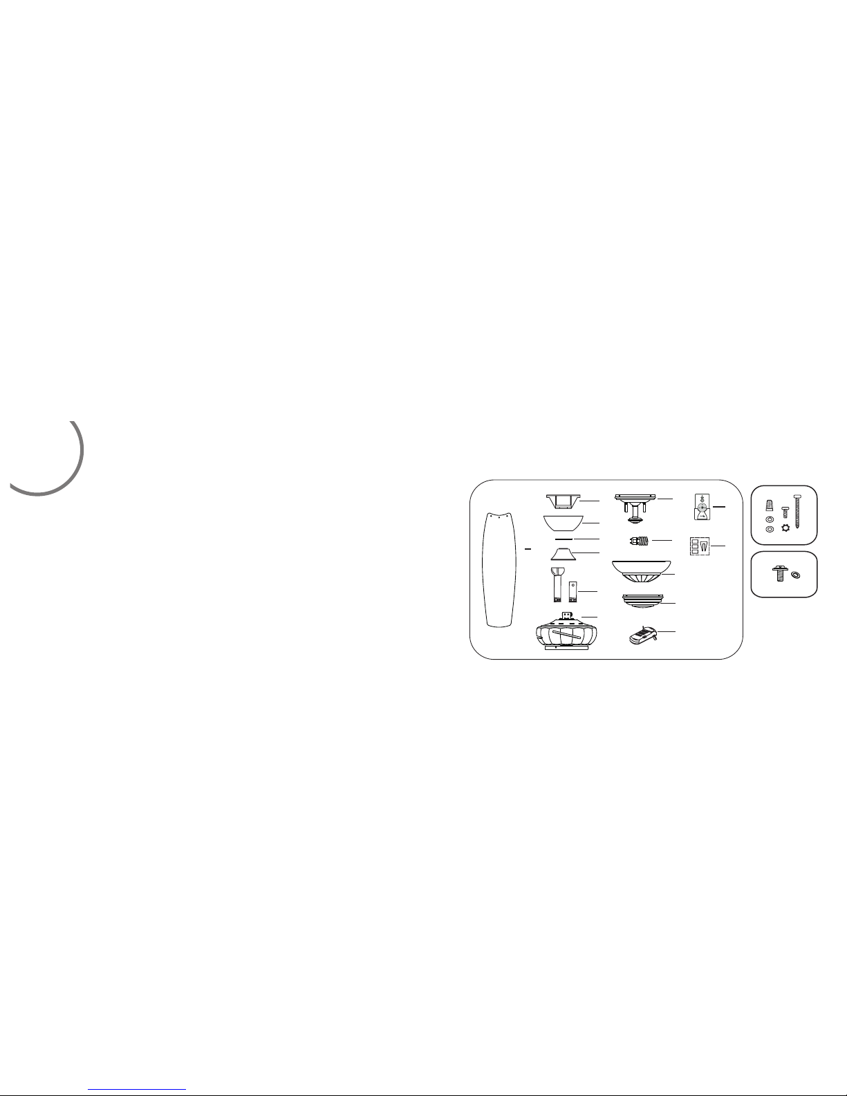
PACKAGE CONTEN TS
Unpac k your fan and check t he conten ts.You should ha ve the following items:
A. Moun ting hardware:
Wire nu ts(3)
Machi ne screws (2)
Wood sc rews (2)
Star wa shers (2)
Lock wa shers (2)
Sprin g washers (2)
B. Blad e attatchment ha rdware:
3/16* 11mm Screws(16 )
Paper w ashers(16)
2
1.
Fan bla des(5)
2.
H
anger b racket
3. C
anopy
4.
Canop y cover
5.
Coupl ing cover
6. Stan dard downrod ass embly(6 ")
Minim um-length down rod(3.5 ")
7. Fan mo tor/housing as sembly
8. Ligh t kit assembly
9.
13W GU2 4 bulb(2)
10. Gla ss shade
1 1. Swit ch cup
1
2 .
Recei ver with 6 wire nuts
13 .Tra nsmitter+hol der+2 mou ting
screw s
14 .Bal ancing kit
1
2
3
4
5
6
7
8
9
10
11
12
13
14
A
B
3
INSTALLING THE FA N
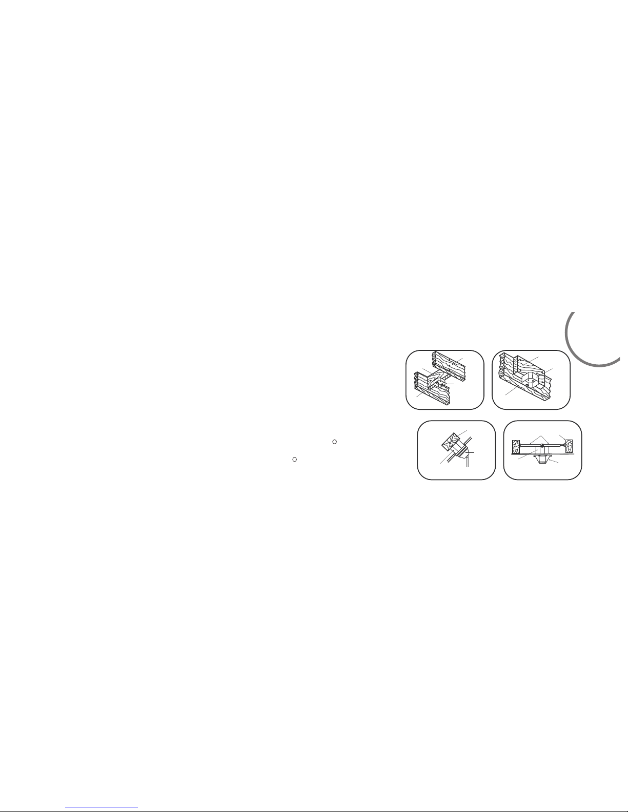
MOUNT ING OPTIONS
If ther e isn't an existin g mountin g box, then read the f ollowing instructions . Disconnect the
power b y removing fuses o r turning o ff circuit break ers.
Secur e the outlet box dir ectly to th e building struc ture. Use appropriate fas teners and
build ing mateials. Th e outlet bo x and its support mu st be able to fully support the m oving
weigh t of the fan (at least 5 0 lbs.).U se a UL listed metal o utlet box . Do not use a plastic
outle t box.
Figur e1,2 and 3 are examp les of diff erent ways to moun t the outlet box.
Note: Y ou may need a longer d ownrod to m aintain proper b lade clearance when insta lling on
R
a steep , sloped ceiling . Longer do wnrods are avail able from y our Minka-Aire deal er.
To hang y our fan where ther e is an exist ing fixture but no c eiling joist, you may need to
R
insta ll a hanger bar as sho wn in Fig.4 (available at yo ur Minka Ai re d ealer or lo cal hardware
store )
Tools R equired: Phili ps screw dr iver, slotted sc rew driver,step-ladde r, wire cutters,electri cal tape.
FIG. 1
CROSS BRAC E
CEILI NG
JOIST
CEILI NG
jOIST
OUTLE T BOX
FIG. 2
PARALL EL WOOD BRACE
(MIN. 2 ’’ THICK )
OUTLE T
BOX
CEILI NG JOIST OR
CROSS BRAC E
FIG. 3
ANGLE D CEILI NG
MAXIM UM 20°ANG LE
PROVI DE
STRON G
SUPPO RT
RECES SED
OUTLE T BOX
HANGE R
OPENI NG
must be
FACING
UPSIDE
FIG. 4
CEILI NG
JOIST
OUTLE T BOX
HANGE R BAR
(OPTI ONAL)
HANGE R
BRACK ET
 Loading...