

minkaAire Light Wave Instruction Manual
CERTIFICATE
Light Wave

Manua l design and all ele ments of ma nual design are pr otected by U.S. Federal and /or State Law, including Pa tent, Trademark and/or Co pyright laws.
The Minka-Aire® warranty is for one (1) year from the date of purchase from an authorized Minka-Aire® dealer.
This warranty is only valid to the original purchaser or user against all defects in material and workmanship light bulbs (
excluded for one full year. Additionally, Minka-Aire® warrants the motor only for the lifetime of the Minka Aire ceiling ) (1)
fan excluding wall controls and electrical components , to the original purchaser or user. ( )
* The warranty is voided with the use of any non- Minka-Aire®electrical devices, E.g., wall controls or electrical dimmer switches, etc…
* The warranty is void once the original purchaser or user ceases to own the fan or the fan is moved from its original point of installation.
* The warranty is void with the use of any hanger bracket (non-Minka Aire or non-fan specific other than the hanger bracket supplied )
& installed
with this specific fan.

Date Purchased Store Purchased Model Number Serial Number
F844
Warranty Service Information
To obtain warranty service during the warranty period, the purchaser should return the fan with the sales receipt to the original place of
purchase. The authorized Minka-Aire® dealer, at its sole discretion, will either repair or replace the fan after verifying the legitimacy of the warranty
claim. Replacement is subject to availability of the same model. If the model is unavailable it will be replaced by one of equal value. This is a limited
warranty; the original purchaser or user is responsible for the cost of removal and reinstallation of repaired or replacement product.
To obtain the name of the Minka-Aire® authorized dealer nearest you call the Minka-Aire® customer care department at 1-800-307-3267, or
contact Minka-Aire® through www.minkagroup.net and select FAQ to answer any questions or if you require additional assistance submit the question
from found there.
CONTENTS
SAFET Y RULES
PACKA GE CONTENTS
INSTA LLING THE FAN
BLADE I NSTALLATION
HANGI NG THE FAN
ELECT RICAL CONNECTI ONS
1
2
3
4
5
6
..... ............ ....... ............ ...............
..... ............ ....... ............ ..
..... ............ ....... ............ ..
..... ............ ....... ...........
..... ............ ....... ............ ......
..... ............ ....... ..
FINIS HING THE INSTALL ATION
INSTA LLING THE 17W LED AS SEMBLY
OPERA TING THE REMOTE CO NTROL/W ALL CONTROL
CARE OF Y OUR FAN
TROUB LESHOOTING
SPECI FICATIONS
7
8
9
10
11
12
..... ............ ....... ............ ................... .
..... ............ ....... ............ ........
..... ..........
..... ............ ....... ............ ................... ................... ....
..... ............ ....... ............ ................... ................... .
..... ............ ....... ............ ................... ................... ........

SAFE TY RULES
1
1.
2. Be cautious! Read al l instructions and safe ty information b efore installi ng your new fan. Review accompan ying assembly di agrams.
3. Make sure that all ele ctrical connec tions comply with local c odes, ordinanc e, or Nat ional Electric al Codes. Hire a qualifie d electrician or
consu lt a do-i t-your self wiring hand book if you are unfamilia r with installin g electrical wiring.
4. Make sure the instal lation site you choose al lows the fan blades to rotate with out any obstruct ions. Allow a minimum clearance of 7 feet
from the floor and 18 inc hes from the top of the blades to the wall.
5. If you are mounting th e fan to a ceiling f an outlet box, use a U.L Listed metal octag onal outlet box marked"Accepta ble For Fan Support".
Secur e the box directly to the building structure. The outlet bo x and its support must be able to support the moving w eight of the fan (at
least 50 pound s). Do no t use a pla stic box.
6. Caution: To reduce the risk of injury use only the screw s provided with the outle t box in conjunction with the lock washers provided with
the fan.
7. If you are mounting th e fan to a joist, ma ke sure it is able t o support the moving weight of the fan (at least 50 po unds).
8. After you install th e fan, make sure that all mounting c omponents are secured to prevent the fan from falling.
9. Do not insert anythi ng into the fan blades while the fan is opera ting.
10. Turn the fan off and wait for the blade s to stop completely befo re performing an y maintenance or cleani ng.
Befor e you beg in installing the fan, sh ut power off the circuit breaker of the fus e box.

NOTE: The important safeguards and instructions appearing in this manual are not meant to cover all possible conditions and
situations that may occur. It must be understood that common sense, caution and care are factors which can not be built into
this product. These factors must be supplied by the person(s) installing, caring for and operating the unit.
NOTE: READ AND SAVE ALL INSTRUCTIONS!
WARNING
TO REDUCE THE RISK OF FIRE,ELECTRIC SHOC K OR OTHE R PERSO NAL INJ URY, MO UNT FAN O NLY TO A U. L LISTED OUTLET BOX OR SUPPORTING
SYSTEM MARKED ACCEPTABLE FOR FAN SUPPO RT AND US E MOUNT ING SCR EWS PRO VIDED W ITH THE O UTLET BOX IN CONJUCTION WITH THE
LOCK WASHERS PROVIDED WITH THE FAN. MOST O UTLET B OXS COM MONLY U SED FOR T HE SUPP ORT OF LI GHTING FIXTURES ARE NOT
ACCEPTABLE FOR FAN SUPPORT AND MAY NEED TO B E REPLA CED. CO NSULT A Q UALIF IDE ELE CTRIC IAN IF IN DOUBT.
TO REDUCE THE RISK OF PERSONAL INJURY, DO NO T BEND TH E BLADE H OLDER S WHILE I NSTAL LING BA LANCING THE BLADES OR CLEANING
THE FAN. DO NOT INSERT FOREIGN OBJECTS BET WEEN RO TATIN G FAN BLA DES.
TO REDUCE THE RISK OF FIRE OR ELECTRONIC SHO CK, THI S FAN ONL Y CAN USE D L-116 7RYS- 02 SOLI D-STATE SPEED CONTROL WITH
DL-4111G-01 REMOTE CONTROL ON LY.
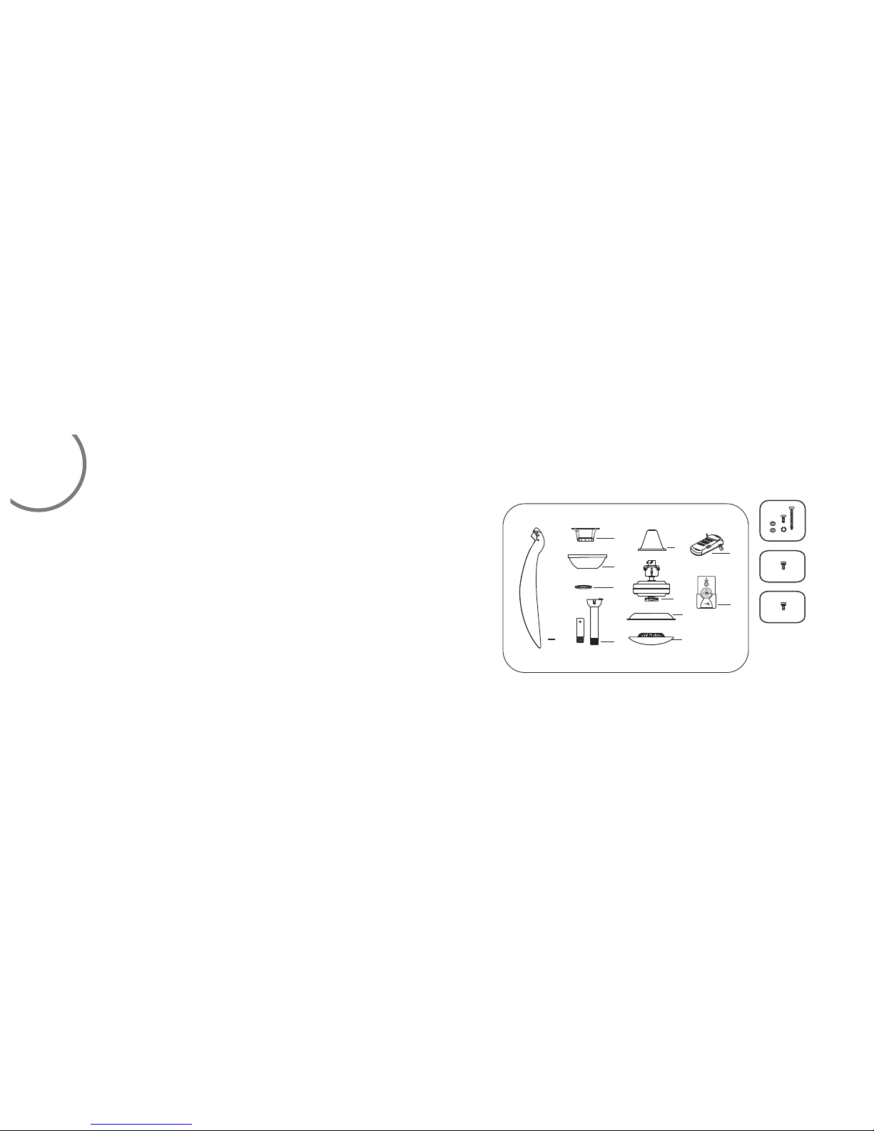
PAC KAGE CONTEN TS
1. Fan bl ades(3)
2. Hang er bracket
3. Cano py
4. Cano py cover
5. Stan dard downrod ass embly (6" )
Minim um-length down rod (4.5" )
6. Coup ling cover
7. Fan mo tor/housing as sembly
8. Flyw heel
9. 17W LE D assembly
10. Rec eiver with 6 wire nu ts
11. Tra nsmitter+hol der+2 mou nting
screw s
A
A. Moun ting hardware:
#8x3/ 4”Machine scre ws (2)
#10x1 .5”Wood screws ( 2)
4mm Sta r washers (2)
Metal w ashers (2)
Lock wa shers (2)
B. Blad e attachment har dware:
1/4“x 15.8mm screws wi th lock
washe rs(10)
C. Flyw heel attachmen t hardwar e:
1/4“x 9.5mm screws wit h lock
washe rs(6)
2
Unpac k your fan and check t he conten ts. You should hav e the following items:
B
1
2
3
4
5
6
7
10
11
8
9
C
 Loading...