

minkaAire Gilera F733 Instruction Manual
GILERA

This product is protected by United States Federal and/or State Law, including Patent, Trademark and/or Copyright laws.
Manual design and all elements of manual design are protected by U.S. Fede
ral and/or State Law, including Patent, Trademark and/or Copyright Laws.

warranty is for one (1) year from the date of purchase from an authorized Minka-Aire dealer.
This warranty is only valid to the original purchaser or user against all defects in material and workmanship (light bulbs
excluded) for one (1) full year. Additionally, Minka-Aire warrants the motor only for the lifetime of the Minka Aire ceiling
fan (excluding wall controls and electrical components), to the original purchaser or user.
The warranty is voided with the use of any non- Minka-Aire electrical devices, E.g., wall controls or electrical dimmer switches, etc...
The warranty is void once the original purchaser or user ceases to own the fan or the fan is moved from its original point of installation.
The warranty is void with the use of any hanger bracket (non-Minka Aire or non-fan specific) other than the hanger bracket supplied & installed
with this specific fan.

Warranty Service Information
To obtain warranty servic during the warranty period, the purchaser should return the fan with the sales receipt to
purchase. The authorized Minka-Aire dealer, at its sole discretion, will either repair or replace the fan after verifying the
®
claim. Replacement is subject to availability of the same model. If the model is unavailable it will be replaced by one of equ
warranty; the original purchaser or user is responsible for the cost of removal and reinstallation of repaired or replacement
To obtain the name of the Minka-Aire authorized dealer nearest you call the Minka-Aire customer care department at 1-800-307-3267, or
contact Minka-Aire through www.minkagroup.net and write to: “Ask Mr. Minka” to answer any questions or if you require assista
®
®
Date Purchased Store Purchased Model Number
®
F733
Serial Number
the original place of
legitimacy of the warranty
al value. This is a limited
product.
nce.

SAFETY FIRST 1
PACKAGE CONTENTS 2
IN INSTALLATION 3
BEG
ING THE FAN 4
HANG
ELECTRI
INSTALLING THE WALL TRANSMITTER
FINISHING THE INSTALLATION 7
CAL CONNECTIONS 5
6
1151W. Bradford Court, Corona CA 92882 For Customer Assistance Call: 1-800-307-3267
ATTACHING THE FAN BLADES 8
OPER
ATING THE REMOTE CONTROL/WALL CONTROL 9
MAINTENANCE 10
TROUBLESHO
SPECIFICATIONS 12
OTING 11
CONTENTS

1. Before you begin installing the fan, shut power off at the circuit breaker of the fuse box.
2. Be cautious! Read all instructions and safety information before installing your new fan. Review accompanying assembly diagrams.
3. Make sure that all electrical connections comply with local codes, ordinances, or National Electrical Codes. Hire a qualified electrician or consult a
do-it-yourself wiring handbook if you are unfamiliar with installing electrical wiring.
4. Make sure the installation site you choose allows the fan blades to rotate without any obstructions. Allow a minimum clearance of 7 feet from
the floor and 18 inches from the tip of the blades to the wall.
5. NOTE: THIS CEILING FAN EXCEEDS THE MAXIMUM WEIGHT SPECIFIED BY UL FOR HANGING FROM A STANDARD OUTLET BOX. SPECIAL
REINFORCEMENT OF THE CEILING IS REQUIRED FOR INSTALLATION.
6. CAUTION: Use the wood screws provided for fan installation. The wood screws must go through the outlet box via the knock outs and secured
directly to the building joist.
7. After you install the fan, make sure that all mounting components are secured to prevent the fan from falling.
8. Do not insert anything into the fan blades while the fan is operating.
9. Turn the fan off and wait for the blades to stop completely before cleaning or performing any maintenance.
1
SAFETY FIRST

NOTE:The important safeguards and instructions appearing in this manual are not meant to cover all possible conditions and situations that may
occur. It must be understood that common sense, caution and care are factors which can not be built into this product. These factors must be
supplied by the person (s) installing, caring for and operating the unit.
NOTE: READ AND SAVE ALL INSTRUCTIONS!
WARNING
SUPPORT DIRECTLY FROM BUILDING STRUCTURE.
TO REDUCE THE RISK OF FIRE, ELECTRIC SHOCK OR OTHER PERSONAL INJURY. MOUNT FAN DIRECTLY TO THE BUILDING JOIST USING TH
WOOD SCREWS AND WASHERS PROVIDED WITH THE FAN. THE WOOD SCREWS MUST GO THROUGH THE OUTLET BOX VIA THE KNOCK
OUTS. CONSULT A QUALIFIED ELECTRICIAN IF IN DOUBT.
TO REDUCE THE RISK OF PERSONAL INJURY, DO NOT BEND THE BLADE HOLDERS WHILE INSTALLING, BALANCING THE BLADES, O
CLEANING THE FAN. DO NOT INSERT FOREIGN OBJECTS BETWEEN ROTATING FAN BLADES.
TO REDUCE THE RISK OF FIRE OR ELECTRIC SHOCK, DO NOT USE THIS FAN WITH ANY SOLID-STATE SPEED CONTROL DEVICE.
TO REDUCE THE RISK OF FIRE OR ELECTRONIC SHOCK, THIS FAN ONLY CAN USE CFR-3T SOLID-STATE SPEED CONTROL WITH TR111A WALL
CONTROL ONLY.
E
R
2
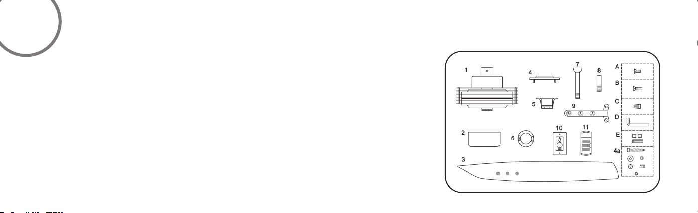
2. Canopy
3. Fan blade
4. Hanger bracket plate
4a.Mounting hardware:
5. Hanger bracket
6.
7.
PACKAGE CONTENTS
1. Fan motor/housing ass'y
M6.5x89mm wood screw (3pcs)
M6.5(Ø6.4x11.3x0.4-1.7mm-12
toothes) washer (3 pcs)
Ø6.5x19x1mm flat washer (3 pcs)
M5 nylon nut (3 pcs)
Ø5x14x1mm flat washer (3 pcs)
3/16" (Ø5.2x8.4x1.00mm) spring washer (3 pcs)
Canopy cover
Standard 6"downrod assembly
Minimum 3-1/2" length downrod (for close
8.
to ceiling mounting only)
9. Blade holder
10. Wall control transmitter include below pcnts
1) big wall plate (2 pcs)
2) small wall plate (2 pcs)
3) screw (6 pcs)
11. Receiver with wire nuts(10pcs)
A. Blade Attachment Hardware:
3/16"x10mm screws(10pcs)
B. Bracket Attachment Hardware:
1/4"-20x13mm screws(7pcs)
C.E.Wire Nut (3 pcs.)
D. L hex wrench
Balance kit
 Loading...