

Minka-Aire F580 User Manual

Congratulations on your purchase of a Minka-AireTM
ceiling fan! Your new fan will be a beautiful addition
to you home, and will keep you comfortable
throughout the year. Minka-AireTM offers a variety
of ceiling fans: combinations of wood and brass
finish, solid designer colors, and unique glass and crystal designs. A
large selection of light fixtures and light kits are also available. Ask
your dealer about accessories that will allow your to customize your
fan.
We're certain that your Minka-AireTM fan will provide you
with many years of comfort, energy savings and satisfaction. To
ensure your personal safety and to maximize the performance of your
fan, please read this manual thoroughly.
LIMITED 30 YEAR WARRANTY
Minka-Aire
TM
warrants this fan to be free from defects in material
and workmanship for one year from the date of purchase, except for
the motor. Minka-Aire
TM
warrants to the original owner that the
motor in this fan shall be free from defects in material and
workmanship for 30 years from the date of purchase. Minka-Aire
TM
only obligation under this limited warranty is to replace, repair or
refund the purchase price for any fan confirmed by Minka-Aire
TM
ro
be defective in material or workmanship after such fan is returned to
Minka-Aire
TM
by the original purchaser along with a proof of
purchase and with shipping charges prepaid. This warranty shall not
apply to fans which have been damaged as a result of improper
installation, removed from the original installation or subjected to
use for which the fan was not designed. The customer shall be
responsible for any cost of removing the old fan, installing a new fan
or any other costs.
This limited 30 year warranty is in lieu of all other expressed
warranties. Minka-AireTM shall under no circumstances be liable for
any incidental or consequential damages.
Date Purchase
Store Purchase
Model Number F580
Serial Number
3
33
0
00
Y
YY RR
W A R R A N T Y
G AR AN TêA DE A„ OS

C
ONTENTS
S
AFETY RULES...................................................................................
P
ACKAGE CONTENTS.....................................................................
I
NSTALLING THE FAN....................................................................
H
ANGING THE FAN........................................................................
E
LECTRICAL CONNECTIONS......................................................
F
INISHING THE INSTALLATION.................................................
A
TTACHING THE FAN BLADES...................................................
S
WITCH CUP INSTALLATION.....................................................
L
IGHT KIT INSTALLATION..........................................................
O
PERATING YOUR FAN...............................................................
C
ARE OF YOUR FAN.....................................................................
T
ROUBLESHOOTING....................................................................
S
PECIFICATIONS.............................................................................
1
2
3
4
5
6
7
8
9
10
11
12
13
1151 W. Bradford court, Corona, CA 92882
and Patents 2003, All Rights Reserved
C
U
L
LISTED
E75795
R

1. S
AFETY
R
ULES
1. Before you begin installing the fan,
shut the power off at the circuit
breaker or the fuse box.
2.Be cautions! Read all instructions
and safety information before
installing your new fan. Review
accompanying assembly diagrams.
3. Make sure that all electrical
connections comply with local codes,
ordinances, or National Electrical
Codes. Hire a qualified electrician or
consult a do-it-yourself wiring
handbook if you are unfamiliar with
installing electrical wiring.
4. Make sure the installation site you
choose allows the fan blades to rotate
without any obstructions. Allow a
minimum clearance of 7 feet from the
floor and the floor to the lowest edge
of the blades 18 inches from the tip of
the blade to the wall.
5.If you are mounting the fan to a
ceiling outlet box, use U.L. Listed
metal octagonal outlet box marked
"Acceptable for fan support". Secure
the box directly to the building
structure. The outlet box and its
support must be able to support the
moving weight of the fan (at least 50
lbs.) Do not use a plastic outlet box.
6. Caution: To reduce the risk of
personal injury use only the screws
provided with the outlet box.
7. If you are mounting the fan to a
joist, make sure it is able to support
the moving weight of the fan (at least
50 lbs.).
8. After you install the fan, make sure
that all mountings are secured to
prevent the fan from falling.
9. Do not insert anything into the fan
blades while the fan is operating.
10. Turn the fan off and wait for it to
stop completely before you attempt to
perform any maintenance or cleaning.
NOTE: The important safeguards
and instructions appearing in this
manual are not meant to cover all
possible conditions and situations that
may occur. It must be understood that
common sense, caution and care are
factors which can not be built into
this product. These factors must be
supplied by the person(s) installing,
caring for and operating the unit.
WARNING
TO REDUCE THE RISK OF FIRE, ELECTRIC SHOCK, OR OTHER PERSONAL INJURY,
MOUNT FAN ONLY TO A U.L. LISTED OUTLET BOX OR SUPPORTING SYSTEM MARKED
ACCEPTABLE FOR FAN SUPPORT AND USE MOUNTING SCREWS PROVIDED WITH THE
OUTLET BOX IN CONJUNCTION WITH THE LOCKWASHERS PROVIDED WITH THE FAN,
MOST OUTLET BOXES COMMONLY USED FOR THE SUPPORT OF LIGHTING FIXTURES
ARE NOT ACCEPTABLE FOR FAN SUPPORT AND NEED TO BE REPLACED. CONSULT A
QUALIFIED ELECTRICIAN IF IN DOUBT.
TO REDUCE THE RISK OF PERSONAL INJURY, DO NOT BEND THE BLADE HOLDERS
WHILE INSTALLING, BALANCING THE BLADES, OR CLEANING THE FAN. DO NOT
INSERT FOREIGN OBJECTS BETWEEN ROTATING FAN BLADES.
TO REDUCE THE RISK OF FIRE OR ELECTRIC SHOCK, DO NOT USE THIS FAN WITH
ANY SOLID-STATE SPEED CONTROL DEVICE
3
1
2
5a
5b
6
7
8
9
4
11
13
14
12
10
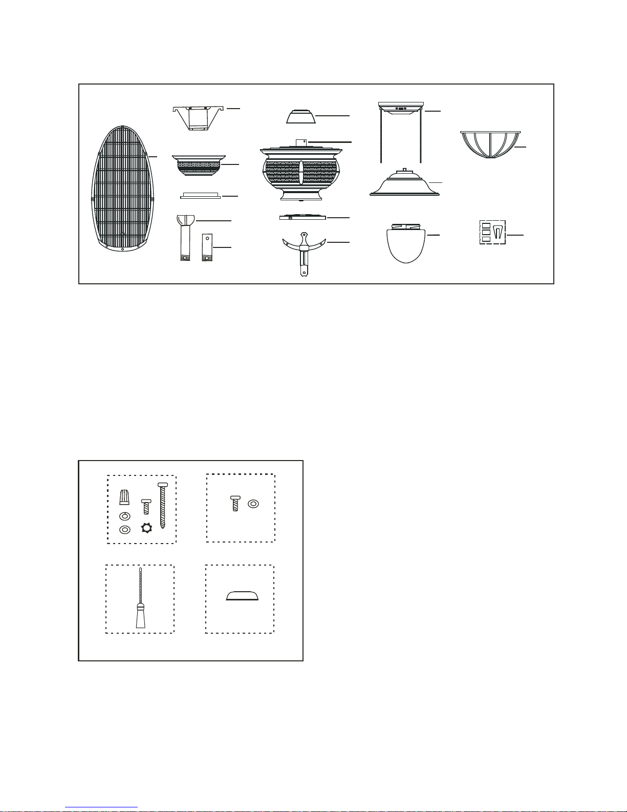
PACKAGE CONTENTS 2.
1. Fan blades (5 )
2. Hanger bracket
3. Canopy
4. Canopy cover
5a. Standard downrod assembly
5b. Minimum-length downrod (for
close to ceiling mounting only)
6. Coupling cover
7. Fan motor/housing assembly
8. Switch cup plate
9. Blade holders (5)
10. Switch housing
11. Light kit
12. Glass shade
13. Glass frame
14. Balancing kit
Unpack your fan and check the contents. You should have the following items:
A
B
C
A. Mounting Hardware:
#10 X 1.5" Wood Screws (2 PCs.)
#8-32 X 3/4" Machine screws (2PCs.)
Lock washers (2 PCs.)
4mm Star washers (2 PCs.)
Wire nuts (3 PCs. )
Washers (2PCs.)
B. Blade Attachment Hardware:
3/16" x 7 mm Screws (21PCs.)
Rubber Washers (21PCs.)
C. Switch Cup Hardware
Pull chain fob (2PCs.)
D. Downrod Rubber Cover
D
3. INSTALLING THE FAN
Tools Required: Phillips screw driver; slotted screw driver; step-ladder; wire cutters;
electrical tape.
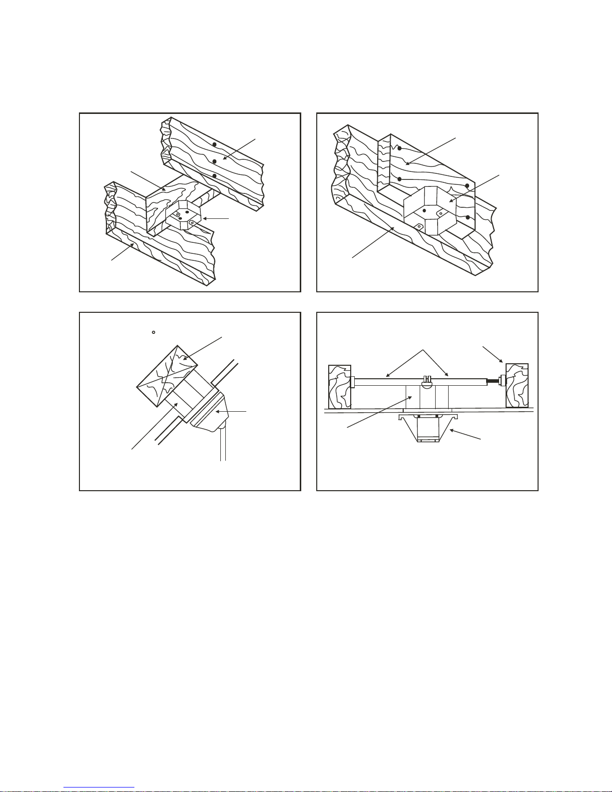
MOUNTING OPTIONS
If there isn't an existing mounting box,
then read the following instructions.
Disconnect the power by removing
fuses or turning off circuit breakers.
Secure the outlet box directly to the
building structure. Use appropriate
fasteners and building materials. The
outlet box and its support must be able
to fully support the moving weight of
the fan (at least 50 lbs.). Use a UL
Listed metal outlet box. Do not use a
plastic outlet box.
Figure 1, 2 and 3 are examples of
different ways to mount the outlet box.
Note:You may need a longer downrod
to maintain proper blade clearance
when installing on a steep, sloped
ceiling. Longer downrods are available
from your
Minka-AireTM dealer.
To hang your fan where there is an
existing fixture but no ceiling joist, you
may need to install a hanger bar as
shown in Fig. 4 (available at your
Minka-AireTM dealer).
FI G. 1
FI G. 3
FI G. 2
FI G. 4
CROSS BRACE
CEILING
JOIST
CEILING
JOIST
CEILING
JOIST
OUTLET BOX
PARALLEL WOO D BRACE
(Min. 2" Thick)
OUTLET
BOX
OUTLET BOX
CEILING JOIST O R
CROSS BRACE
ANGLED CEILIN G
MAXIMUM 17 ANGLE
PROVIDE
STRONG
SUPPORT
RECESSED
OUTLET BOX
HANGER
OPENING
MUST BE
FACING
UPSIDE
HANGER BAR
(OPTIONAL)
HANGER
BRACKET
 Loading...