

minkaAire F548 Instruction Manual

Limited Lifetime Warranty
Minka-Aire warrants to the original owner that this fan will be free from defects
in material and workmanship for one year from the date of purchase, excluding the
motor. Minka-Aire warrants to the original owner that the motor in this fan shall
be free from defects in material and workmanship for as long as the original purchaser owns the fan, and it remains in the original installation.
This is a limited warranty. Minka-Aire's only obligation under this limited
warranty is to replace or repair, or refund the purchase price, in Minka-Aire's sole
discretion without charge to the original owner, of the fan once Minka-Aire confirms that the fan has a defect covered by this limited warranty.
Call our customer service department at 1-800-307-3267 to obtain the name of
the Minka-Aire authorized dealer closest to your location, or contact us through
our web site, www.minkagroup.net and write to: ask Mr. Minka if you have any
questions or require further assistance.
To obtain warranty service, the owner should return the fan along with proof of
purchase to a Minka-Aire authorized dealer. The Minka-Aire authorized dealer
shall then, at its sole discretion: repair the fan, replace the fan, refund the purchase
price less the amount directly attributable to the consumer's prior usage of the fan,
or if necessary instruct the consumer to contact Minka-Aire directly for warranty
service. Minka-Aire will be responsible for the cost of any repair, or replacement
for any warranty service provided by a Minka-Aire authorized dealer for product
under warranty.
You may also at your preference obtain warranty service by returning the fan
directly to Minka-Aire along with proof of purchase, your name and return address,
and a description of the claimed product defect. Pack carefully; damage sustained
in return transit to Minka Aire will be the original owner's responsibility. Original
owner shall be responsible to pay all shipping charges. To obtain warranty service,
you may return a fan that proves to be defective during the warranty period to the
following address:
Minka-Aire
Warranty service
1151 W. Bradford Court
Corona, CA 92882
This warranty shall not apply to fans which have been damaged in any way,
including improper installation, damage as a result of the removal of the fan from
the original installation, or damage in shipping. This warranty shall not apply to
fans which have been subjected to use for which the fan was not designed. The
purchaser of the fan shall be responsible for any cost of removing the old fan,
installing a new fan, or any other costs.
This limited warranty is in lieu of all other express warranties. This limited
warranty excludes all incidental and consequential damages, and Minka-Aire shall
not under any circumstances be liable for incidental or consequential damages.
Some States do not allow the exclusion of or limitation of incidental or consequential damages, so the foregoing limitation or exclusion may not apply to you.
This warranty gives you specific legal rights, and you may also have other
rights which vary from State to State.
We encourage you to promptly complete and return the enclosed warranty
registration card. However, return of the warranty registration card is not a condition of this warranty.
MKA4122201-F548”¢Œ˜-1222 1905/3/24, 10:44 PM1

CONTENTS
SAFETY FIRST ............................................................ 1
P
ACKAGE CONTENTS ................................................... 2
B
EGIN INSTALLATION ................................................... 3
H
ANGING THE FAN...................................................... 4
E
LECTRICAL CONNECTIONS ........................................... 5
F
INISHING THE INSTALLATION ......................................... 6
A
TTACHING THE FAN BLADES........................................ 7
A
TTACHING THE LIGHT KIT & GLASS............................ . 8
O
PERATING YOUR FAN ................................................ 9
M
AINTENANCE ......................................................... 10
T
ROUBLESHOOTING ................................................... 11
S
PECIFICATIONS ........................................................ 12
1151 W. Bradford Ct., Corona, CA 92882
All Rights Reserved
MKA4122201-F548”¢Œ˜-1222 1905/3/24, 10:44 PM2

1. Before you begin installing the fan,
disconnect the power by removing
fuses or turning off circuit breakers.
2. Be Cautious! Read all instructions
and safety information before
installing your new fan. Review the
accompanying assembly diagrams.
3. Make sure that all electrical
connections comply with local codes,
ordinances, or National Electrical
Codes. Hire a qualified electrician or
consult a do-it-yourself wiring
handbook if you are unfamiliar with
installing electrical wiring.
4. Make sure the installation site you
choose allows the fan blades to
rotate without any obstructions.
Allow a minimum clearance of 7
feet from the floor to the lowest edge
of the blades. Fan blades must have a
minimum clearance of 18" from
the wall.
5. If you are mounting the fan to a
ceiling outlet box, use a metal
octagonal outlet box. Secure the box
directly to the building structure. The
outlet box and its support must be
able to support the moving weight of
the fan (at least 50 lbs.). Do not use
a plastic outlet box.
6. Attach the hanger bracket using the
hardware supplied with the fan.
7. If you are mounting the fan to a
joist, make sure it is able to support
the moving weight of the fan (at least
50 lbs.).
8. After you install the fan, make sure
that all connections are secure to
prevent the fan from falling.
9. Do not insert anything into the fan
blades while fan is operating.
10. Turn the fan off and wait for it to
stop before reversing fan direction.
NOTE: The important safeguards and
instructions appearing in this manual
are not meant to cover all possible
conditions and situations that may
occur. It must be understood that
common sense, caution and care are
factors which can not be built into this
product. These factors must be supplied
by the person(s) installing, caring for
and operating the unit.
1. SAFETY FIRST
MKA4122201-F548”¢Œ˜-1222 1905/3/24, 10:44 PM3
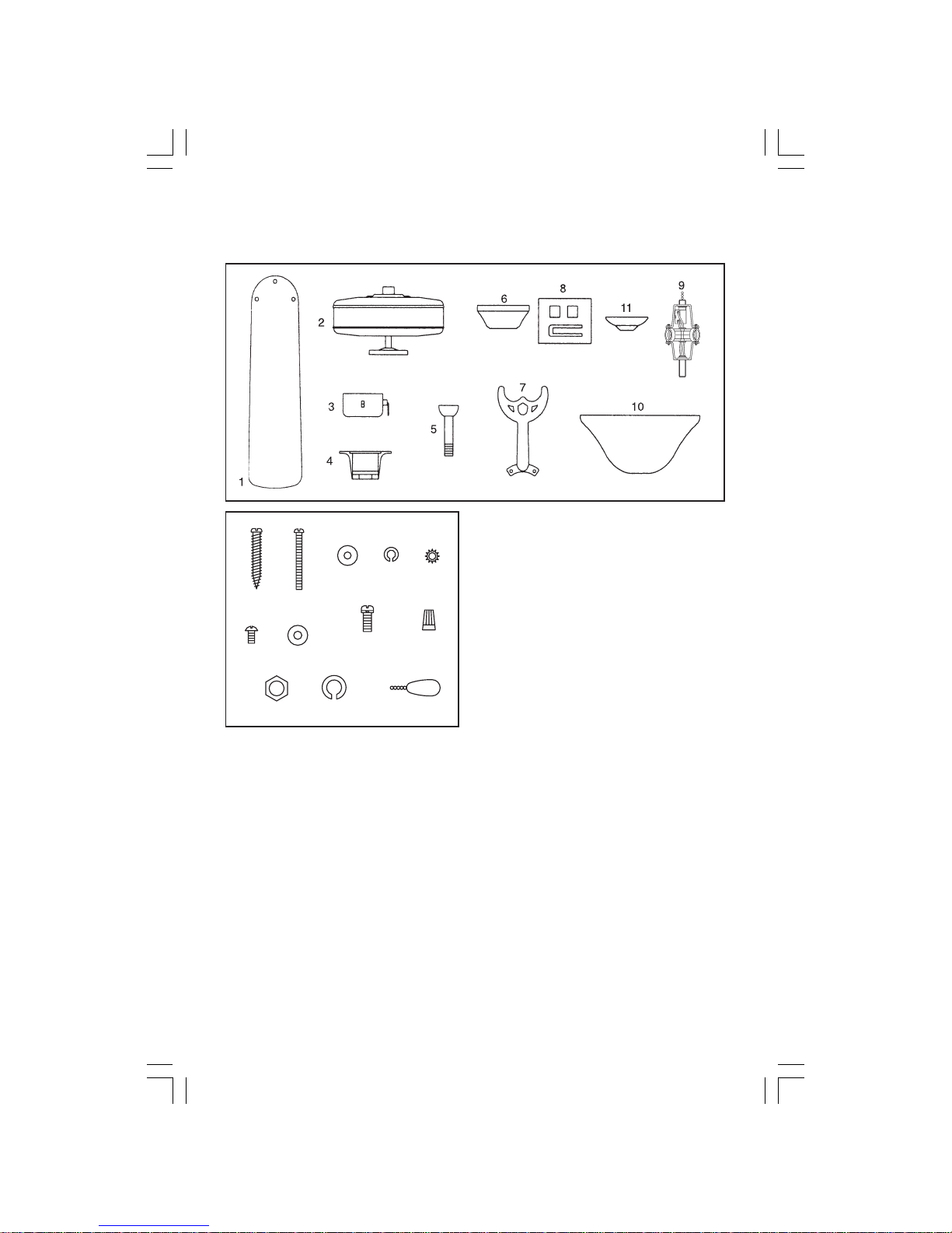
Unpack your fan and check the contents.
You should have the following items:
1. Fan Blades (5 pcs.)
2. Fan Motor/Housing Assembly
3. Switch Cup
4. Hanger Bracket
5. Standard Downrod Assembly
6. Canopy
7. Blade Bracket (5 pcs.)
8. Balancing Kit
9. Light Kit
10. Glass Shade
11. Glass Cap
PACKAGE CONTENTS 2.
Mounting Hardware:
J-Box Mounting:
(A)10
#
x 1- 1⁄2"L (10# x
38mm) wood screws
(2 pcs.)
Hanger Bracket Mounting:
(B)8-32x 1- 1⁄2" (8-32 x
38mm) screws (2 pcs.)
(C)Metal Washers (2 pcs.)
(D)Lockwashers (2 pcs.)
(E)Wire Nut (3 pcs.)
(I)Star washer (2 pcs.)
Blade Attachment Hardware:
(F)3⁄16"-24 x 5⁄16"L
(3⁄16"-24 x 8mm) flange
head screws (16 pcs.)
(G)Fiber Washers (16 pcs.)
Blade Holder Hardware:
(H)1⁄4"-20 x 7⁄16"L (1⁄4"-20 x 11mm)
screws w/lockwashers (11 pcs.)
Switch Cup Hardware:
(L) Pull Chain Fob (2 pcs.)
Light Kit Hardware:
(J)1⁄8NPS-4mm Nut (1 pcs.)
(K)Spring Washer (1 pcs.)
C
D
J
G
H
I
F
A
B
L
E
K
MKA4122201-F548”¢Œ˜-1222 1905/3/24, 10:44 PM4
OUTLET BOX
CEILING
JOIST
CEILING
JOIST
CROSS BRACE
3. BEGIN INSTALLATION
Tools Required: You will need a phillips screw driver, slotted screw
driver, adjustable wrench, stepladder, wire cutters, and electrical tape.
CEILING JOIST OR
CROSS BRACE
PARALLEL WOOD BRACE
(Min. 2" Thick)
OUTLET
BOX
HANGER BAR
(OPTIONAL)
CEILING
JOIST
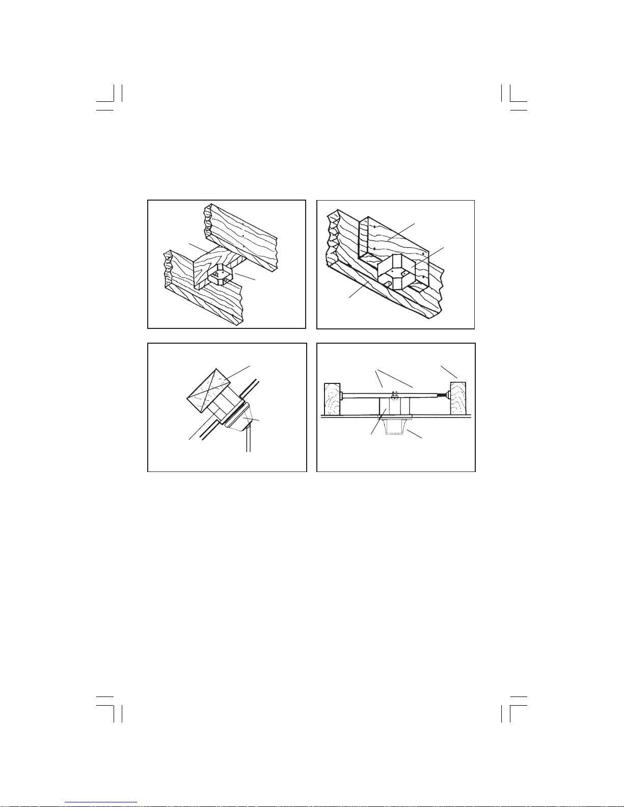
MOUNTING OPTIONS
Figures 1, 2 and 3 are examples of
different ways to mount the outlet
box. Note: You may need a longer
downrod to maintain proper blade
clearance when installing on a
steep, sloped ceiling. Longer
downrods are available from your
Minka-Aire
® dealer.
To hang your fan where there is
an existing fixture but no ceiling
joist, you may need to install a
hanger bar as shown in Figure 4
(available at your Minka-Aire
®
dealer).
If there isn't an existing mounting
box, then read the following
instructions. Disconnect the power
by removing fuses or turning off
circuit breakers.
Secure the outlet box directly to the
building structure. The outlet box
and its support must be able to fully
support the moving weight of the
fan (at least 50 lbs.). Use a U.L.
Listed metal outlet box. Do not use
a plastic outlet box.
FIG. 1
FIG. 3
FIG. 2
FIG. 4
RECESSED
OUTLET
BOX
Angled Ceiling
Maximum 29
° angle
PROVIDE
STRONG
SUPPORT
HANGER
BRACKET
OUTLET BOX
HANGER
OPENING
MUST BE
FACING
UPSIDE
MKA4122201-F548”¢Œ˜-1222 1905/3/24, 10:44 PM5
REGISTRATION
SLOT
HANGING THE FAN 4.
SET
SCREWS
HANGER BRACKET
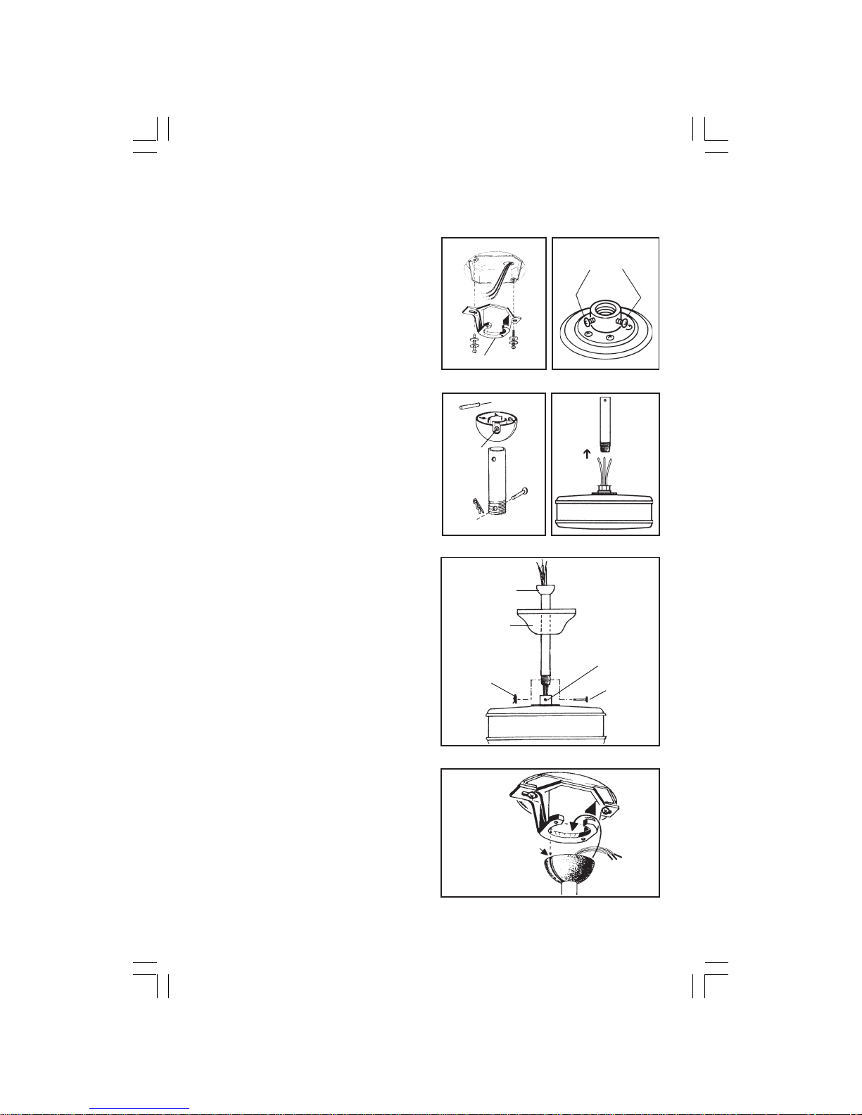
REMEMBER to turn off the power.
Follow the steps below to hang
your fan properly:
Step 1. Secure the hanger bracket
to the ceiling outlet box using
screws, lock washers, and flat
washers included with the fan.
(Fig. 5)
Step 2. Loosen the two set screws
in the top coupling of the motor
assembly. (Fig. 6)
Step 3. Remove downrod hanger
ball by loosening set screw,
removing the cross pin, and
sliding ball off rod. Remove the
hitch pin and lock pin. (Fig. 7)
Step 4. Carefully feed fan wires up
through the downrod. (Fig. 8)
Thread the rod into the coupling,
next line up holes, secure with the
lock pin and hitch pin. Tighten set
screws. (Fig. 9)
Step 5. Slip canopy onto downrod.
(Fig. 9). Carefully reinstall hanger
ball onto rod being sure that
crosspin is in correct position, set
screw is tight and wires are not
twisted.
Step 6. Now lift motor assembly
into position and place downrod
ball into hanger bracket. Rotate
until the check groove has dropped
into the registration slot and seats
firmly. (Fig. 10). Rod should not
rotate if this is done correctly.
DOWNROD
HITCH
PIN
SET
SCREW
LOCK
PIN
SUPPLY
WIRES
FIG. 6
FIG. 7
FIG. 8
FIG. 9
FIG. 10
HANGER BALL
CANOPY
HITCH PIN
SET
SCREW
FAN HOUSING
LOCK PIN
CROSS PIN
MKA4122201-F548”¢Œ˜-1222 1905/3/24, 10:44 PM6
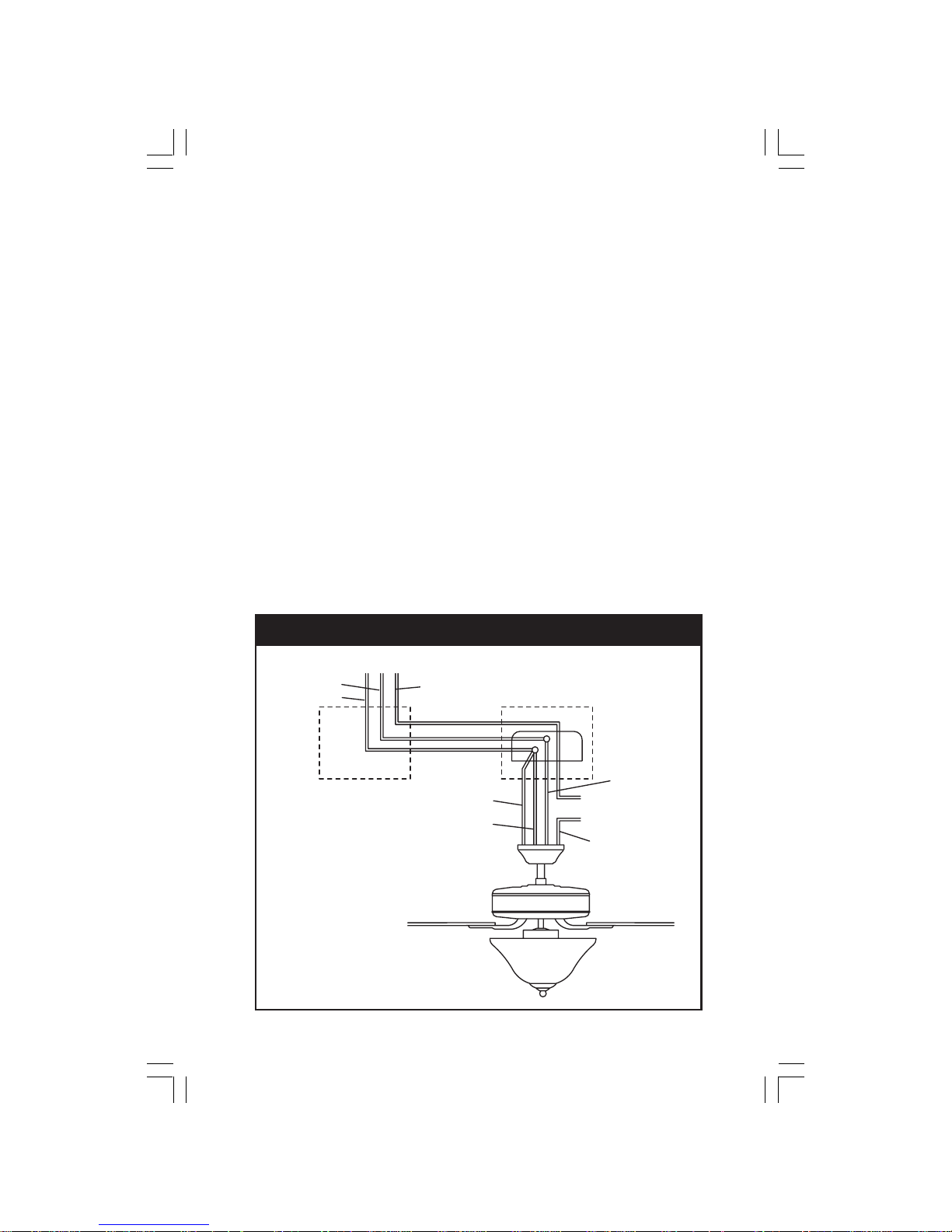
FIG. 11
5. ELECTRICAL CONNECTIONS
REMEMBER to shut the power off
at the circuit breaker or fuse box.
Follow the steps below to
connect the fan to your house
supply wires. Use the wire nuts
supplied with your fan. Secure the
wire nuts by wrapping the
connection with electrical tape.
Step 1. Connect the black (hot)
wire from the ceiling to the black
and the blue wires from the fan.
Connect the white (Neutral) wire
from the ceiling to the white wire
from the fan. (Fig 11)
Step 2. If your outlet has a
ground wire (Green or Bare
Copper) connect the fan ground
wires (on hanger ball and hanger
bracket) to it; otherwise,
connect the fan ground wire on
hanger ball directly to hanger
bracket (Fig. 11)
Step 3. Figure 12 & 13 Illustrate
the wiring connections using
optional wall unit. (Available at
your Minka-Aire
® Retailer.)
NOTE: If a light kit is not included
with your fan, one can be
purchased at you Minka-Aire
®
Retailer.
HOUSE WIRE SUPPLY
WHITE(NEUTRAL)
BLACK(HOT)
GREEN(GROUND)
WALL
CEILING
BLUE(OPTIONAL LIGHT)
BLACK(MOTOR)
WHITE(NEUTRAL)
GROUND-(CONNECT
TO GROUND WIRE
ON HANGER
BRACKET IF NO
HOUSE GROUND
WIRE EXISTS.)
FAN CONTROLLED BY PULL CHAIN. LIGHT KIT CONTROLLED BY PULL CHAIN.
MKA4122201-F548”¢Œ˜-1222 1905/3/24, 10:44 PM7
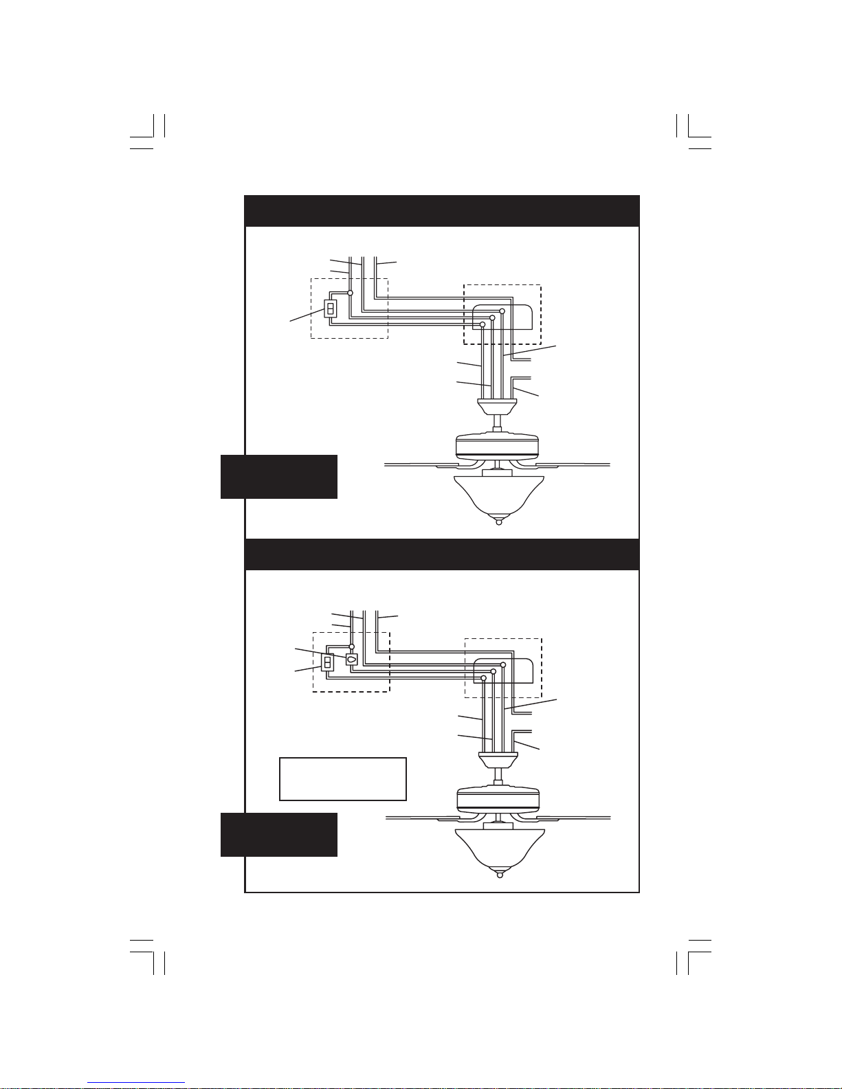
FIG. 12
FAN CONTROLLED BY PULL CHAIN. LIGHT KIT CONTROLLED BY WALL SWITCH.
WIRING
OPTION 1
WHITE(NEUTRAL)
BLACK(HOT)
GREEN(GROUND)
WALL
CEILING
BLUE(OPTIONAL LIGHT)
BLACK(MOTOR)
WHITE(NEUTRAL)
GROUND-(CONNECT
TO GROUND WIRE
ON HANGER
BRACKET IF NO
HOUSE GROUND
WIRE EXISTS.)
FAN CONTROLLED BY PULL CHAIN. LIGHT KIT CONTROLLED BY WALL SWITCH.
FIG. 13
WIRING
OPTION 2
HOUSE WIRE SUPPLY
LIGHT
SWITCH
HOUSE WIRE SUPPLY
WHITE(NEUTRAL)
BLACK(HOT)
GREEN(GROUND)
LIGHT
SWITCH
FAN WALL
CONTROL
WALL
CEILING
WHITE(NEUTRAL)
BLUE(OPTIONAL LIGHT)
BLACK(MOTOR)
GROUND-(CONNECT
TO GROUND WIRE
ON HANGER
BRACKET IF NO
HOUSE GROUND
WIRE EXISTS.)
NOTE:SOME WALL UNITS
INCORPORATE BOTH LIGHT
SWITCH AND FAN WALL
CONTROL IN ONE HOUSING.
MKA4122201-F548”¢Œ˜-1222 1905/3/24, 10:44 PM8
 Loading...