

Minka-Aire ARTEMIS XL5 Instruction Manual

This product is protected by United States Federal and/or State Law, including Patent, Trademark and/or Copyright laws.
Manual design and all elements of manual design are protected by U.S. Federal and/or State Law, including Patent, Trademark and/or Copyright laws.
The Minka-Aire® warranty is for one (1) year from the date of purchase from an authorized Minka-Aire® dealer.
This warranty is only valid to the original purchaser or user against all defects in material and workmanship light bulbs (
excluded for one full year. Additionally, Minka-Aire® warrants the motor only for the lifetime of the Minka Aire ceiling ) (1)
fan excluding wall controls and electrical components , to the original purchaser or user. ( )
* The warranty is voided with the use of any non- Minka-Aire®electrical devices, E.g., wall controls or electrical dimmer switches, etc…
* The warranty is void once the original purchaser or user ceases to own the fan or the fan is moved from its original point of installation.
* The warranty is void with the use of any hanger bracket (non-Minka Aire or non-fan specific other than the hanger bracket supplied )
& installed
with this specific fan.

Date Purchased Store Purchased Model Number Serial Number
F905
Warranty Service Information
To obtain warranty service during the warranty period, the purchaser should return the fan with the sales receipt to the original place of
purchase. The authorized Minka-Aire® dealer, at its sole discretion, will either repair or replace the fan after verifying the legitimacy of the warranty
claim. Replacement is subject to availability of the same model. If the model is unavailable it will be replaced by one of equal value. This is a limited
warranty; the original purchaser or user is responsible for the cost of removal and reinstallation of repaired or replacement product.
To obtain the name of the Minka-Aire® authorized dealer nearest you call the Minka-Aire® customer care department at 1-800-307-3267, or
contact Minka-Aire® through www.minkagroup.net and write to: “Ask Mr. Minka” to answer any questions or if you require assistance.

CONTENTS
INSTALLING THE LIGHT PLATE
INSTALLING THE LIGHT BULB & GLASS SHADE
FAN WITHOUT GLASS SHADE AND BULB
OPERATING THE REMOTE CONTROL/WALL CONTROL
CARE OF YOUR FAN
TROUBLESHOOTING
SPECIFICATIONS
SAFETY RULES
PACKAGE CONTENTS
INSTALLING THE FAN
HANGING THE FAN
ELECTRICAL CONNECTIONS
FINISHING THE INSTALLATION
BLADE INSTALLATION
INSTALLING THE MOUNTING PLATE
1
2
3
4
5
6
7
8
9
10
11
12
13
14
15
..........................................................
..............
..............................................................................
...........................................................................
..................................................................................
...................................................
......................................
......................................
..........................................
..........................
....................
.......................................
.............................
...................................
...........

SAFETY RULES
1
1.
2. Be cau ti ou s! R ea d all instructions and safety information before installing your ne w fa n. Review accompanying assembly diagrams.
3. Make sure th at a ll electrical connections comply with local codes, ordinance, or Na ti on al E le ct ri ca l Codes. Hire a qualified electrician or
consult a do-it-your se lf w ir in g handbook if you are unfamiliar with installing electrical wir in g.
4. Make sure th e in st al la ti on site you choose allows the fan blades to rot at e wi th ou t any obstructions. Allow a minimum clearance of 7 feet
from the floor an d 18 inches from the top of the blades to the w al l.
5. If you are m ou nt in g the fan to a ceiling fan outlet box, us e a U.L Listed metal octagonal outlet box marked"Acceptable For Fan Sup po rt ".
Secure the box di re ct ly t o the building structure. The outlet box and its su pp or t mu st be able to support the moving weight of the fa n (at
least 50 pounds). Do no t use a plastic box.
6. Caution: To re du ce t he risk of injury use only the screws provided wi th t he outlet box in conjunction with the lock washers pr ov id ed wit h
the fan.
7. If you are m ou nt in g the fan to a joist, make sure it is a bl e to support the moving weight of the fan (at l ea st 50 pounds).
8. After you in st al l th e fan, make sure that all mounting components are sec ur ed t o prevent the fan from falling.
9. Do not ins er t an yt hi ng into the fan blades while the fan is ope ra ti ng .
10. Turn the fa n of f and wait for the blades to stop completely be fo re p er fo rm in g any maintenance or cleaning.
Before you begin in st al li ng t he fan, shut power off the circuit breaker of the f us e box.

NOTE: The importan t safeguards and instructions appearing in this ma nual are not meant to cover all possible conditions an d
situations that ma y occur. It must be understoood that common sense,ca ution and care are factors which can not be built into
this product. Thes e factors must be spplied by the person(s) installin g, caring for and operating the unit.
NOTE: READ AND SAVE ALL INSTRUCTIONS!
WARNING
TO REDUCE T HE R ISK OF FIRE,ELECTRI C SH OCK OR OTHER PERSONAL INJ UR Y, MOUNT FAN ONLY TO A U.L LI ST ED OUTLET BOX OR SUPPORTI NG
SYSTEM MA RK ED ACCEPTABLE FOR FAN S UP PORT AND USE MOUNTING SCR EW S PROVIDED WITH THE OUT LE T BOX IN CONJUCTION WITH TH E
LOCK WASH ER S PROVIDED WITH THE FAN . MO ST OUTLET BOXS COMMONLY U SE D FOR FAN SUPPORT OF LIGH TI NG FIXTURES ARE NOT
ACCEPTA BL E FOR FAN SUPPORT AND NEE D TO B E REPLACED. CONSULT A QUA LI FIDE ELECTRICIAN IF I N DO UBT.
TO REDUCE T HE R ISK OF PERSONAL INJUR Y, D O NOT BEND THE BLADE HOLDER S WH ILE INSTALLING BALA NC ING THE BLADES OR CLEANIN G
THE FAN. DO N OT I NSERT FOREIGN OBJEC TS B ETWEEN ROTATING FAN BLA DE S.
TO REDUCE T HE R ISK OF FIRE OR ELECTRON IC S HOCK, THIS FAN ONLY CAN USE D L- 4510 REMOTE CONTROL O NL Y.
ATTENTION: The Energy Policy Act of 2005 requi res this fan to be equipped with a 190 watt limiting device, If lamping exceeds
190watts, the ceiling fan’s light kit will shut off automatically.
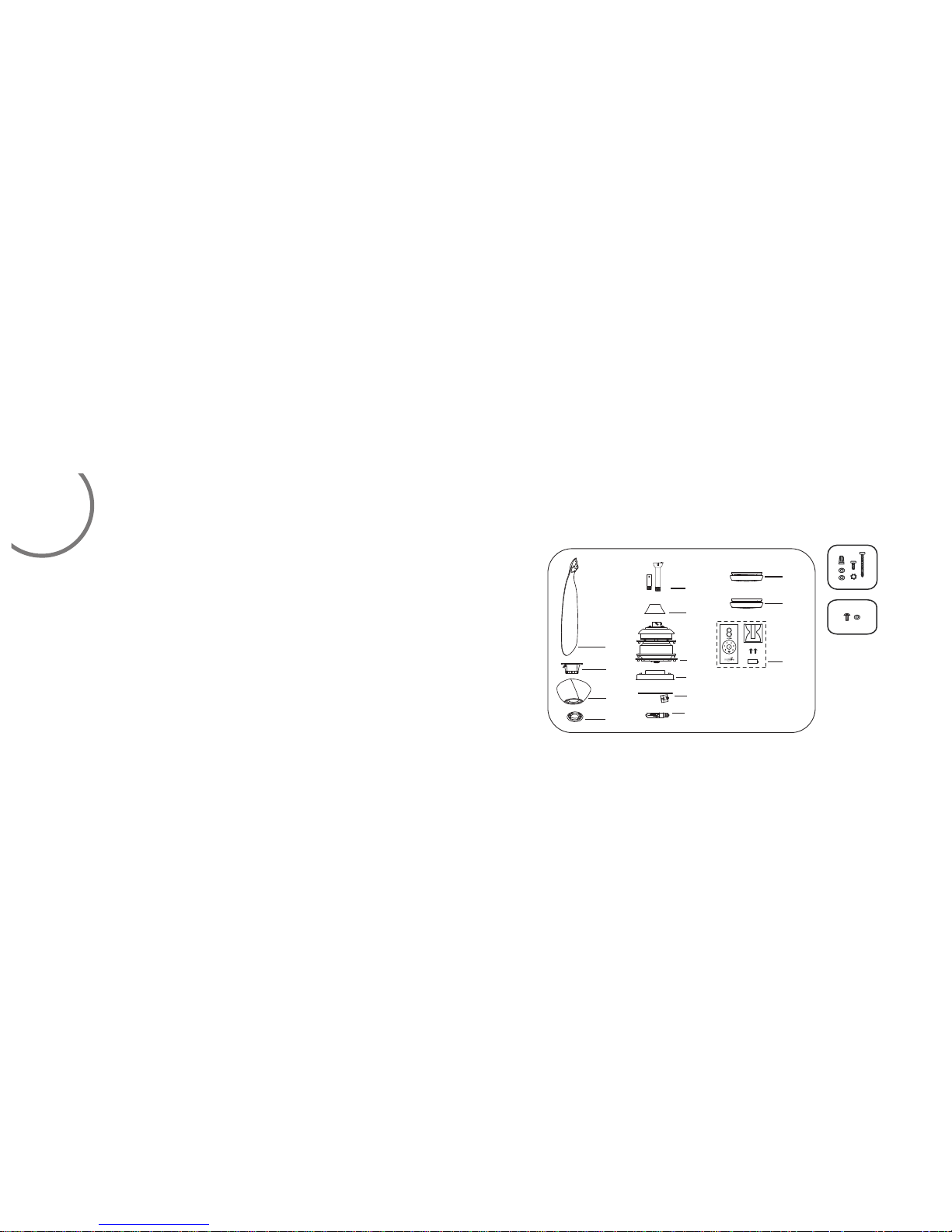
PACK A GE CONTENTS
1. Fan blades(5)
2. Hanger bracket
3. Canopy
4. Canopy cover
5. Standard downrod assembly(6")
Minimum-length downrod(3.5")
6. Coupling cover
7. Fan motor/housing assembly
8. Mounting plate
9. Light plate
10. 100Watt halogen bulb
1 1. Glass shade
12. Metal shade
A
13. Transmitter + holder + 2mounting
screws + A23 12 volt battery
A. Mounting hardware:
Wire nuts(3)
#8x3/4”Machine screws (2)
#10x1.5Wood screws (2)
4mm Star washers (2)
Metal washers (2)
Lock washers (2)
B. Blade attachment hardware:
3/16“x 12.7 mm screws (16)
Metal washers (16)
2
Unpack your fan and check the contents. You should have the following items:
B
1
2
3
4
5
6
7
8
9
10
11
12
13
3
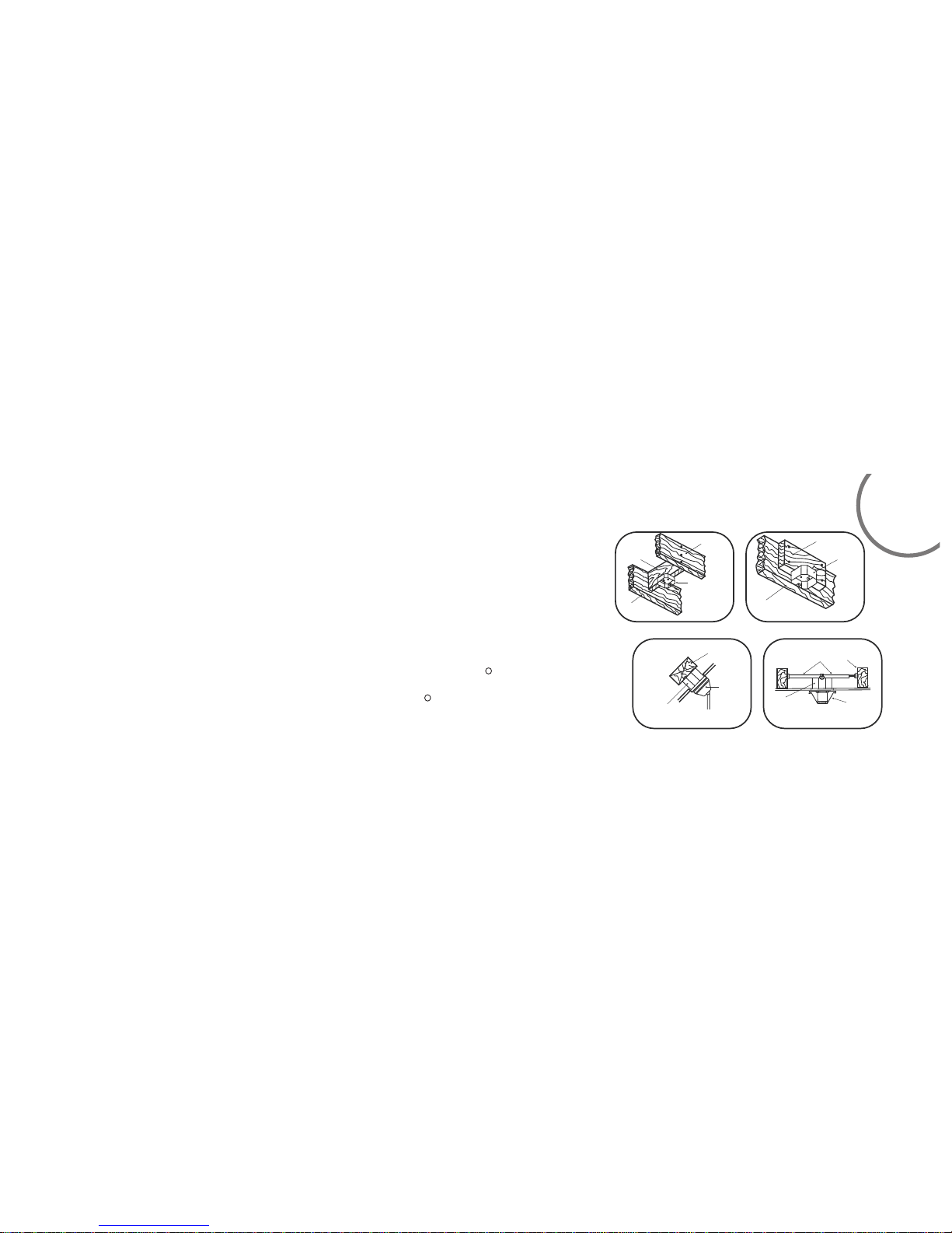
INSTALLING THE FAN
FIG. 1
CROSS BRAC E
CEILI NG
JOIST
CEILI NG
jOIST
OUTLE T BOX
FIG. 2
PARALL EL WOOD BRACE
(MIN. 2 ’’ THICK )
OUTLE T
BOX
CEILI NG JOIST OR
CROSS BRAC E
FIG. 3
ANGLE D CEILI NG
MAXIM UM 18° ANG LE
PROVI DE
STRON G
SUPPO RT
RECES SED
OUTLE T BOX
HANGE R
OPENI NG
must be
FACING
UPSIDE
FIG. 4
CEILI NG
JOIST
OUTLE T BOX
HANGE R BAR
(OPTI ONAL)
HANGE R
BRACK ET
MOUNTING OPTIONS
If there isn't an existing mounting box, then read the following instructions. Disconnect the
power by removing fuses or turning off circuit breakers.
Secure the outlet box directly to the building structure. Use appropriate fasteners and
building materials. The outlet box and its support must be able to fully support the moving
weight of the fan (at least 50 lbs.).Use a UL listed metal outlet box.
Do not use a plastic outlet box.
Figure1,2 and 3 are examples of different ways to mount the outlet box.
Note: You may need a longer downrod to maintain proper blade clearance when installing on
R
a steep, sloped ceiling. Longer downrods are available from your Minka-Aire dea le r.
To hang your fan where there is an existing fixture but no ceiling joist, you may need to
R
install a hanger bar as shown in Fig.4(available at your Minka Aire dea le r or l oc al h ar dw ar e st or e) .
Tools Required: Philips screw driver, slotted screw driver, step-ladder, wire cutters, electrical tape.
 Loading...