

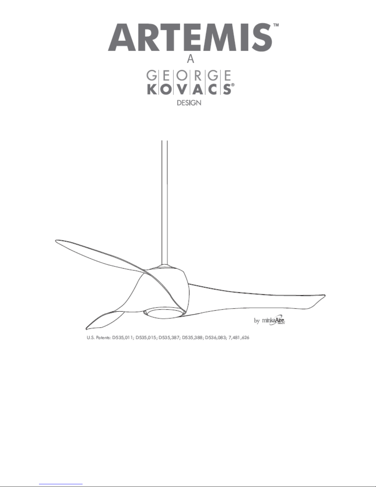
minkaAire Artemis F803 Instruction Manual
V1.0
INSTRUCTION MANUAL WARRANTY CERTIFICATE
2
ENGLISH .................................................................................................................................................... 3
GERMAN...................................................................................................................................................... 17
SPANISH.........................................................................................................................................................34
ITALIAN.........................................................................................................................................................48
DUTCH..........................................................................................................................................................62
FRENCH....................................................................................................................................................... 76
CONTENTS
3
Congratulations
on purchasing your new Artemis ceiling fan by Minka Aire. This is an extremely high
quality
product
and we are sure that you will be very happy with your purchase.
1. This appliance is NOT intended for use by persons (including children) with reduced physical, sensory or mental
capabilities, or lack of experience and knowledge, unless they have been given supervision or instruction concerning
use of the appliance by a person responsible for their safety.
2. Children should be supervised to ensure that they do not play with the appliance.
3. The all-poles disconnection must be incorporated in the fixed wiring in accordance with the wiring rules.
4. Meaning of crossed-out wheeled dustbin: Do not dispose of electrical appliances as unsorted municipal waste, use
separate collection facilities. Contact your local government for information regarding the collection systems available.
If electrical appliances are disposed of in landfills or dumps, hazardous substances can leak into the groundwater
and get into the food chain, damaging your health and well-being.
5. The structure to which the fan is to be mounted must be capable of supporting a weight of 48kg.
6. The fan should be mounted so that the blades are at least 2.3 meters above the floor in Europe.
7. The fan should be mounted so that the blades are at least 2.1 meters above the floor in Australia.
8. The fan is designed for indoor use only. Mounting the fan in a situation where it is subject to water or moisture is
dangerous.
9. Only an authorized electrician should execute the installation.
Note: The important safeguards and instructions given in this manual are not meant to cover all possible
condi-
tions
and situations that may occur. It must be understood that common sense, caution and care are
factors
which cannot
be built into any
product.
FAN CONTROL
Your warranty will be void if a solid-state dimmer type fan controller or other brand wall controller is used. ONLY
use the wall controller supplied.
FAN INSTALLATION
Under our warranty terms this ceiling fan must be installed by a licensed electrician. This fan is designed for indoor
use only, mounting where the fan is subject to water or moisture can be dangerous and also void the warranty.
FAULT FINDER
Always check the “Trouble Shooting Checklist” included in this booklet.
MECHANICAL NOISE MAY BE NOTICED ON INSTALLATION, PLEASE ALLOW AT LEAST 8 HOURS
SETTLING-IN PERIOD. SOME FANS WOBBLE MORE THAN OTHERS—EVEN IN THE SAME MODEL; IT
DOES NOT MEAN THE FAN IS FAULTY
SAFETY PRECAUTIONS
IMPORTANT NOTES
4
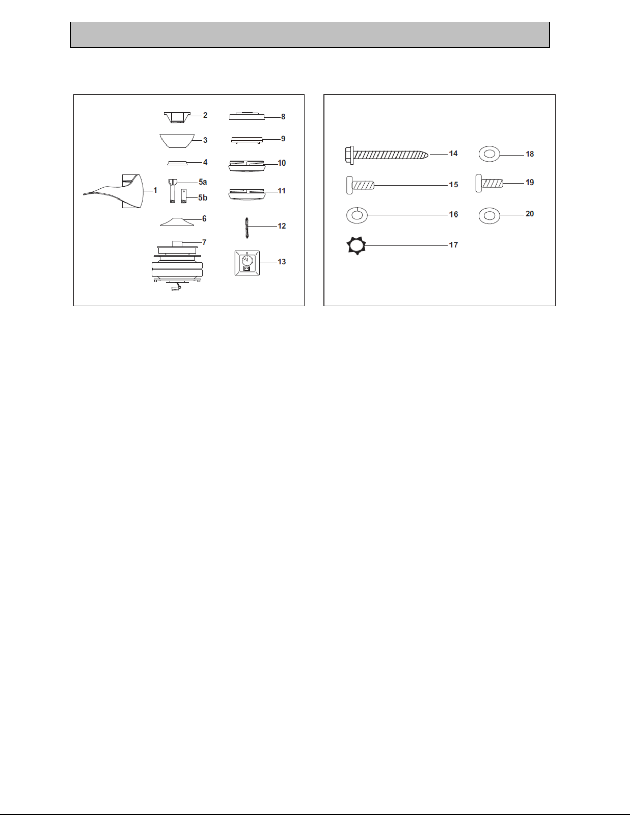
Unpack your fan and check contents. You should have the following:
1.
Fan blades x 3
11.
Optional switch cup cover x 1
2.
Hanger bracket x 1
12.
80W R7S halogen bulb x 1
3.
Canopy x 1
13.
Wall control Incl. 2 mounting screws x 1
4.
Canopy cover x 1
14.
#10 x 38mm Wood screws x 2
5a.
Standard downrod assembly x 1
15.
#8 x 19mm Machine screws x 2
5b.
Minimum-length downrod (for close to ceiling
mounting only) x 1
16.
Lock washers x 2
6.
Coupling cover x 1
17.
4mm Star washers x 2
7.
Fan motor/housing assembly x 1
18.
Washers x 2
8.
Light kit mounting plate x 1
19.
4.8mm x 17mm screws x 10
9.
Light plate x 1
20.
Flat washers x 10
10.
Glass shade x 1
PACKAGE CONTENTS
5
TOOLS REQUIRED:
- Phillips / Flat head screw driver
- Pair of pliers
- Adjustable Spanner
- Step ladder
- Wire cutter
- Wiring.
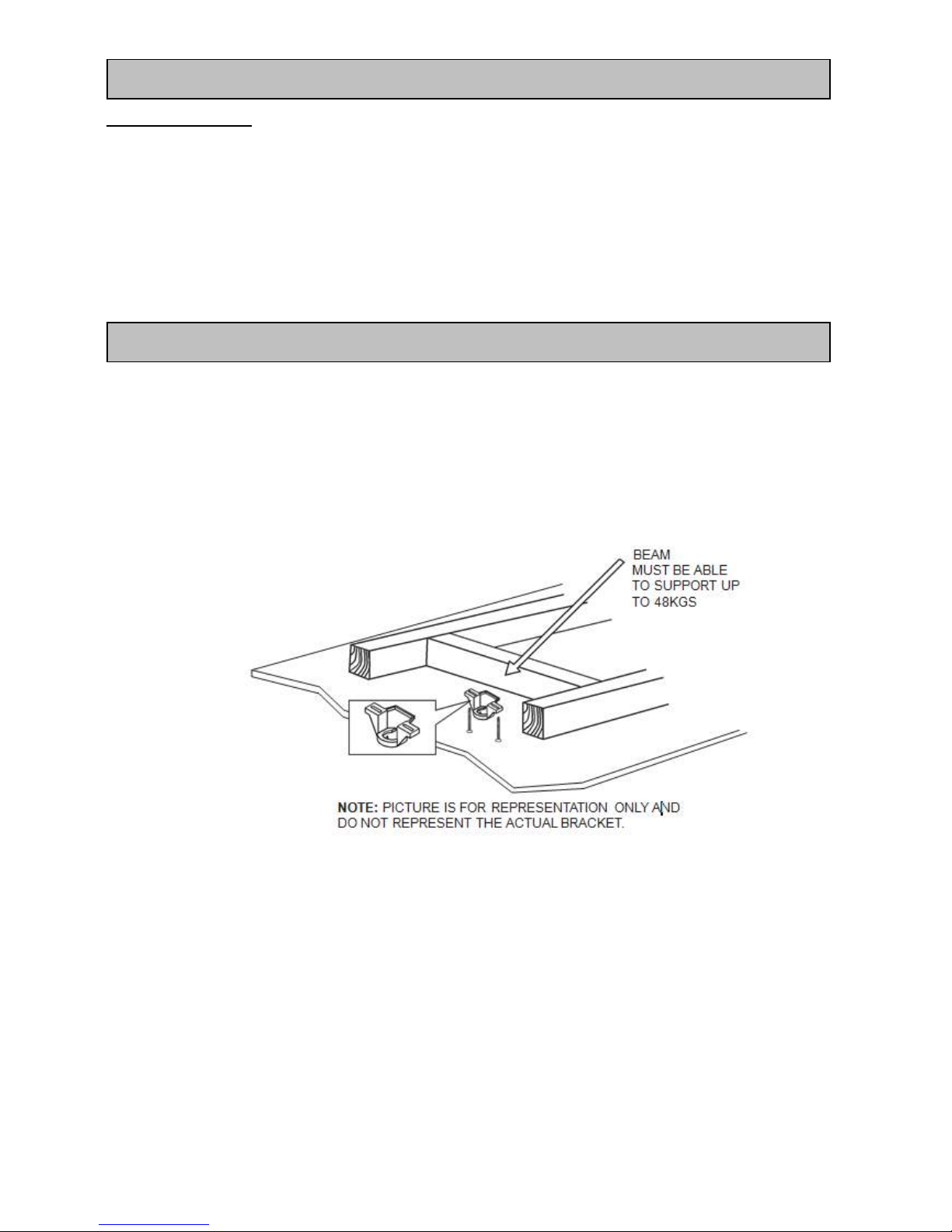
The ceiling must be installed in a location so that the blades are at least 300mm spacing from the tip of the blade to
the nearest objects or walls.
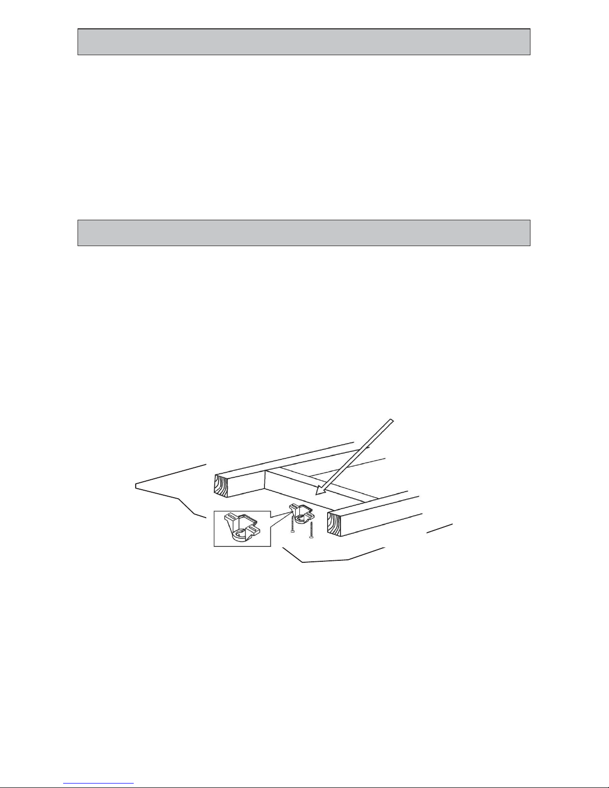
Secure the hanging bracket to the ceiling joist or structure that is capable of carrying a load of at least 48KG, with
two long screws provided. Ensure at least 30mm of the screw is threaded into the support.
Fig. 1
NOTE: The bracket screw provided is for use with wooden structure only. For structures other than wood,
the appropriate screw type MUST be used.
TOOLS REQIRED
INSTALLING THE MOUNTING BRAKCET
6
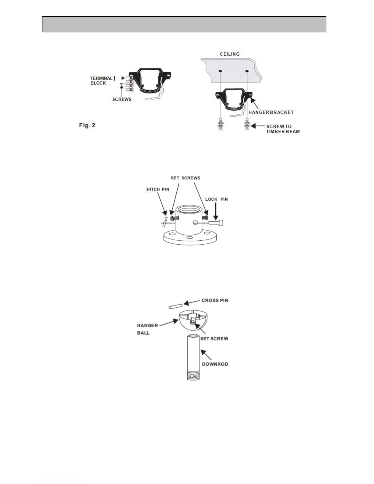
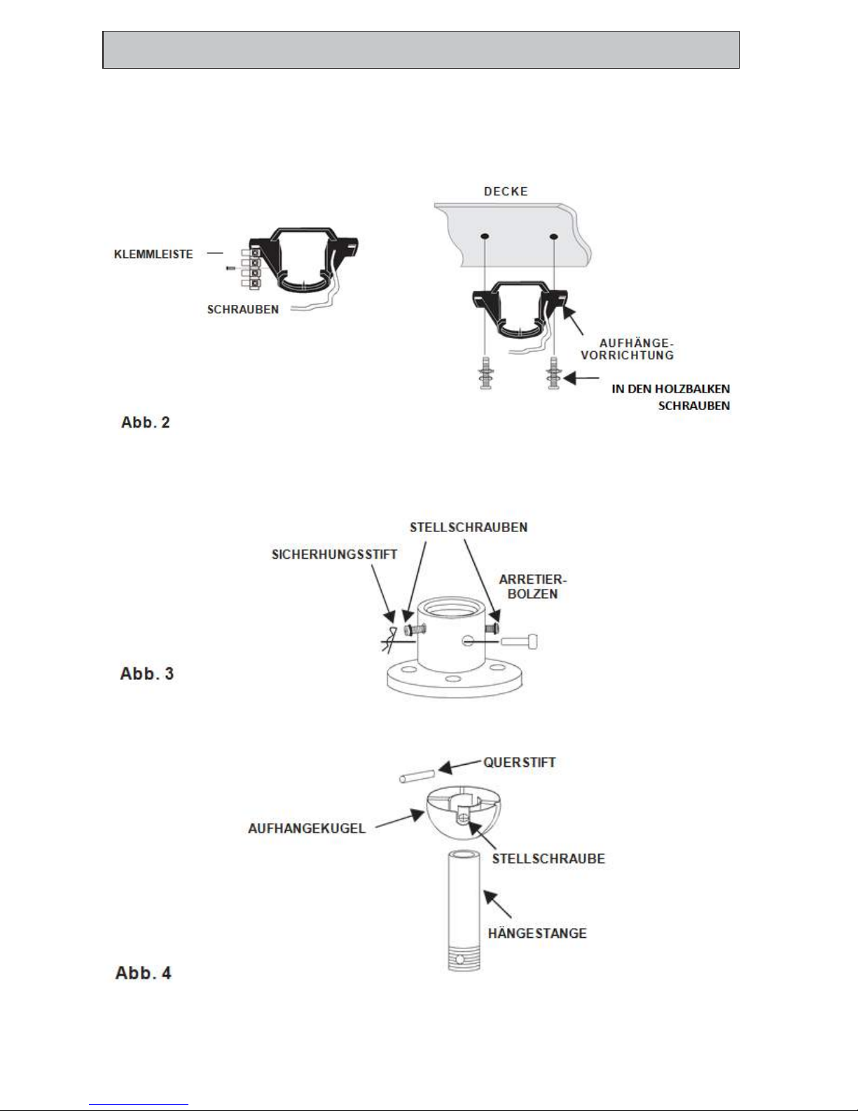
Loosen the screw in the terminal block and remove the terminal block for later use. Secure the hanger bracket to the
ceiling joist or structure using the screws included. Re-install the terminal block back to hanger bracket.
Loosen the two set screws and remove the hitch pin and lock pin from the top coupling of the motor
assembly.
Fig.3
Remove hanger ball from downrod assembly by loosening set screw, removing the cross pin, and sliding ball off rod.
Fig.4
HANGING THE FAN

7
Carefully feed fan wires up through the downrod, Then thread the rod into the coupling. Line up holes and replace lock
pin and hitch pin. Tighten set screws
Fig.5
Slip coupling cover, canopy cover and canopy onto downrod. Install two screws into coupling cover and tighten
screws to fix it. Carefully reinstall hanger ball onto rod being sure that cross pin is in the correct position, set screws
are tighten and wires are not twisted.
Fig. 6
8
Now lift motor assembly into position and place hanger ball into hanger bracket. Rotate until the check notch has
dropped into the registration slot and seats firmly. Rod should not rotate if this is done correctly.
Fig.7
WARNING: FOR YOUR SAFETY ALL ELECTRICAL CONNECTIONS MUST BE UNDERTAKEN BY A LICENCED
ELECTRICIAN
NOTE: AN ADDITIONAL ALL POLE DISCONNECTION SWITCH MUST BE INCLUDED IN THE FIXED WIRING.
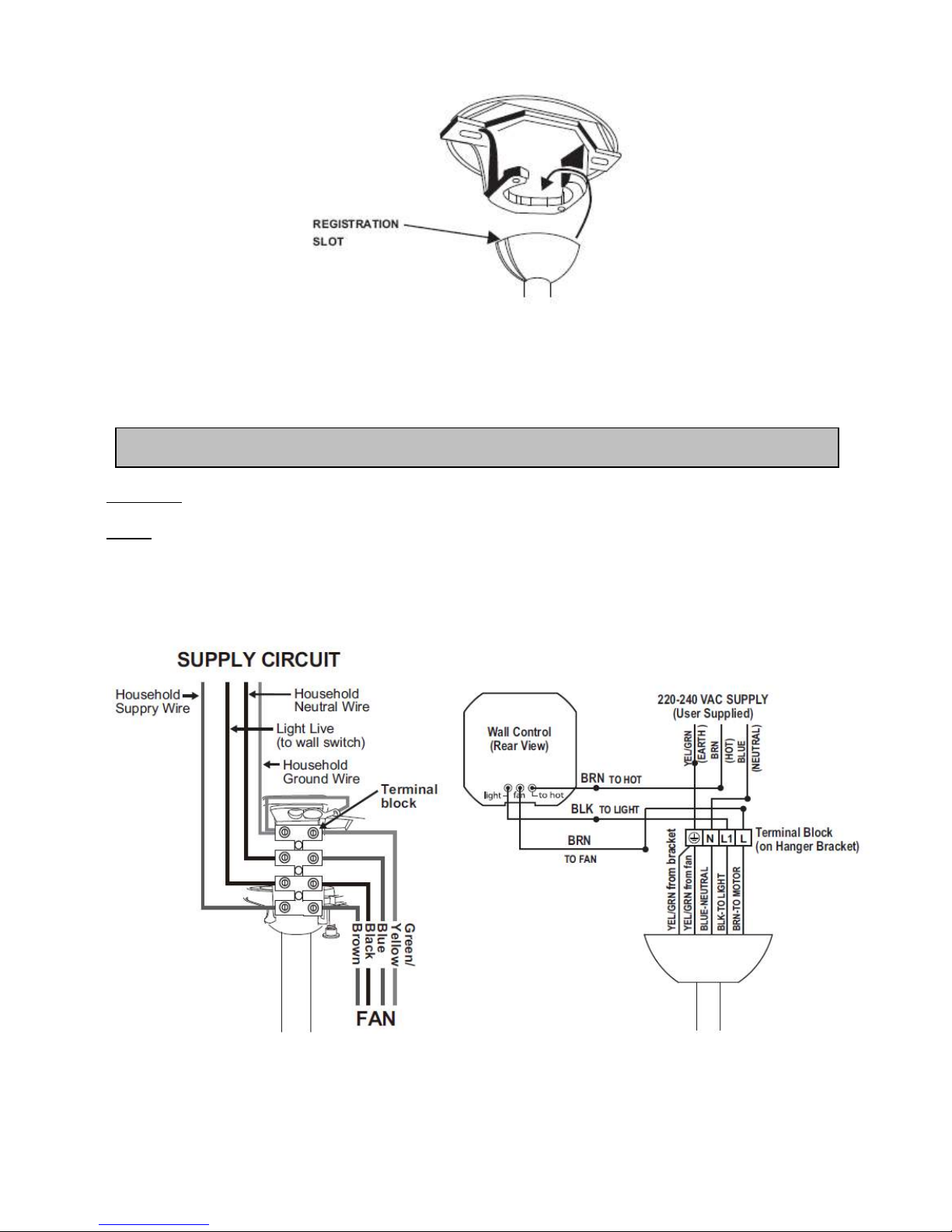
Make wiring connection as following:
Fig. 8
ELECTRICAL WIRING DIAGRAM
9
Carefully tuck the wire connections inside the outlet box or wall cavity if not using an outlet box. Use the screws
provided to secure the wall switch and wall plate to the outlet box or wall switch frame.
Fig. 9
Note: Outlet box is not included, and can be supplied separately by the Electrician.
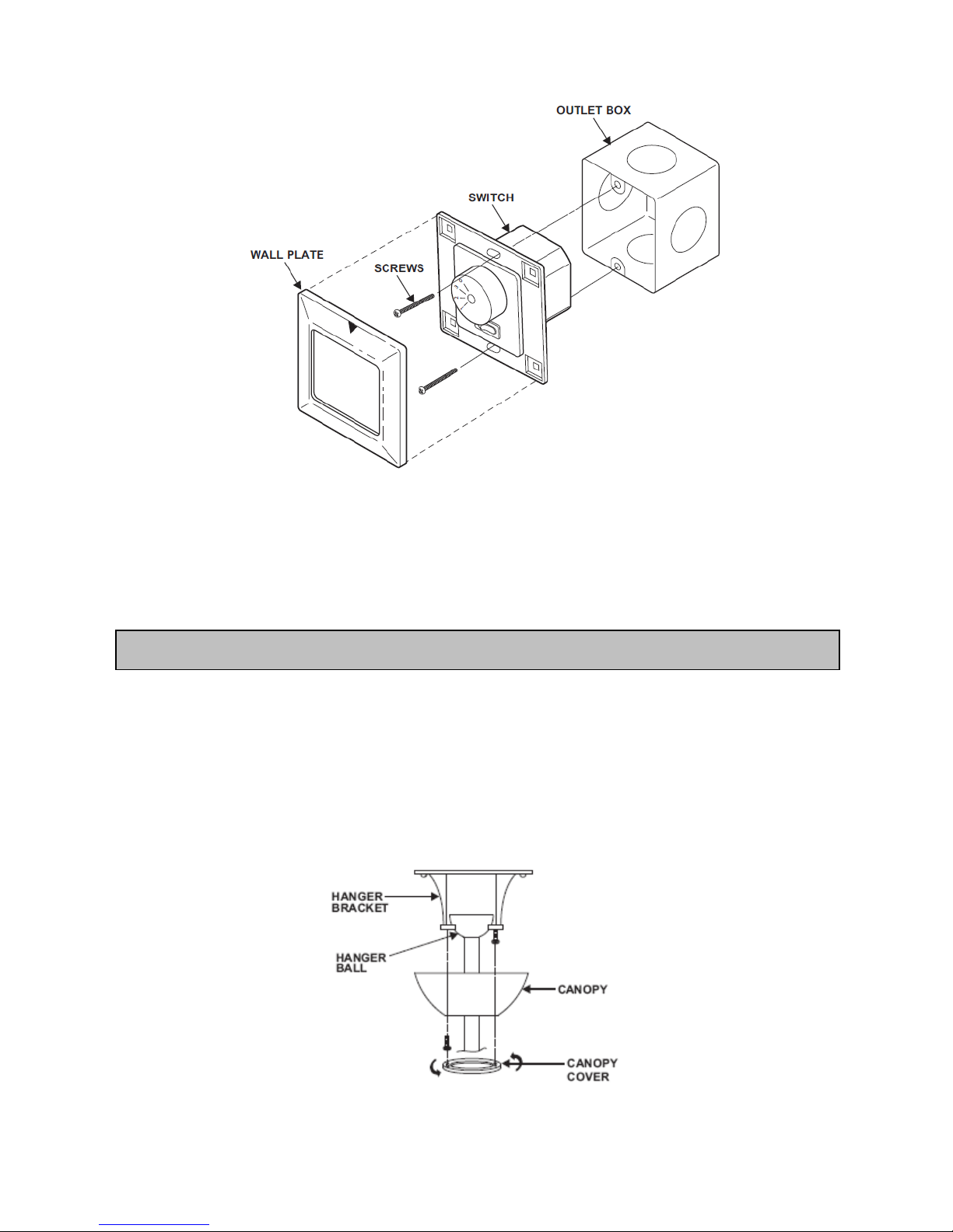
1. Remove the 1 of 2 screws from the bottom of the hanger bracket and loosen the other one a half turn from the
screw head.
2. Slide the canopy up to hanger bracket and place the key hole on the canopy over the screw on the hanger
bracket, turn canopy until it locks in place at the narrow section of the key holes.
3. Align the circular hole on canopy with the remaining hole on the hanger bracket, secure by tightening the two
set screws.
NOTE: Adjust the canopy screws as necessary until the canopy and canopy cover are snug.
Fig. 10
FINISHING THE INSTALLATION
10
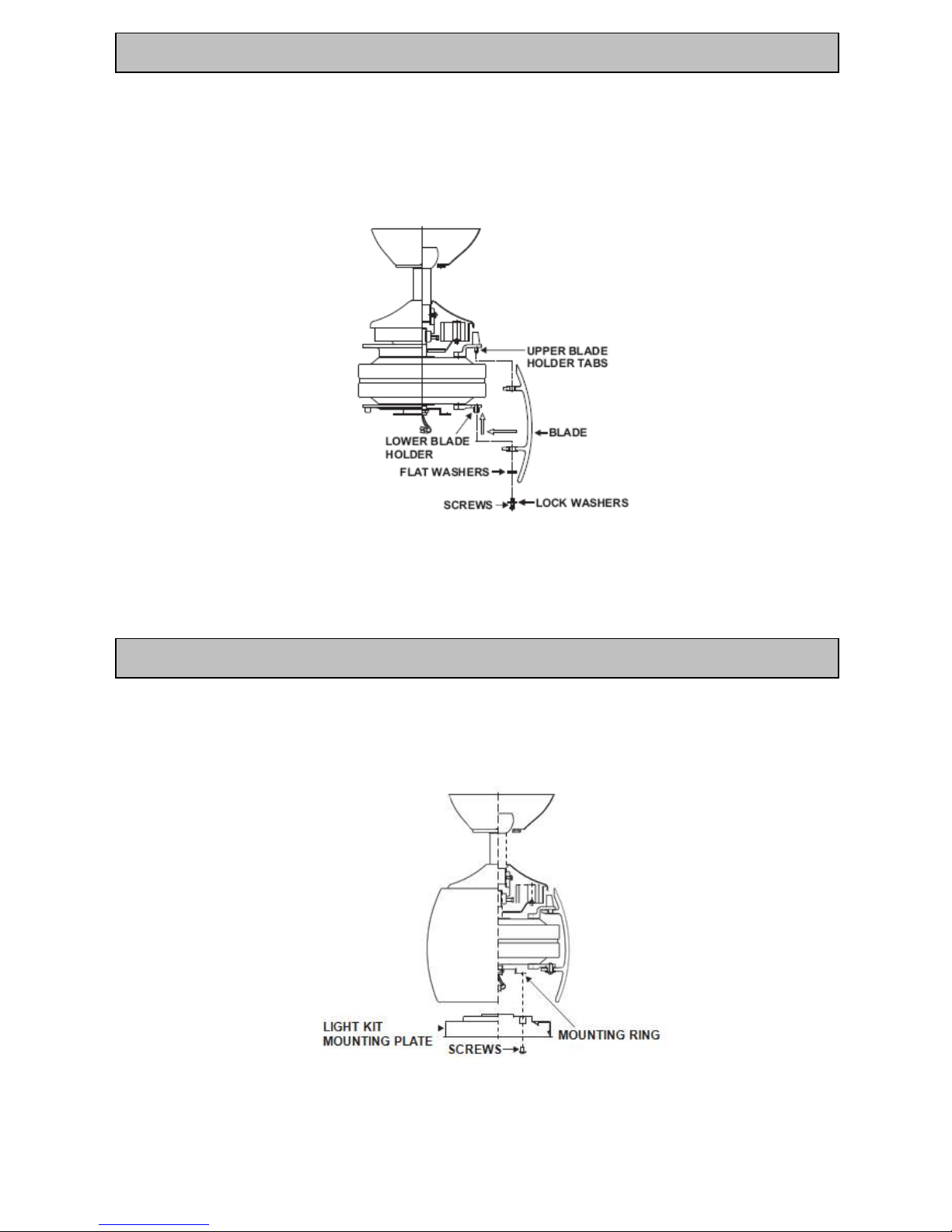
1. Align and engage the top holes from one of the blades to the upper blade holder tabs. Carefully align the
bottom holes from the blade to the holes from the lower blade holder. Secure blade with with 3 screws, lock
washers and flat lock washers provided. Follow the same process for the remaining two blades.
2. All blade sets are grouped together by weight. Because plastic materials vary in density, the fan may wobble
even though the blades are weight matched
Fig. 11
NOTE: You must attach the blades to the motor housing after mounting the motor to the ceiling. When installing
more than one fan, ensure that the blades sets are not mixed up as each set is dynamically balanced.
1. Remove 3 screws from the mounting ring
2. Place the light kit mounting plate to the mounting ring, secure by tightening the 3 screws previously removed.
Fig. 12
INSTALLING THE MOUNTING PLATE
BLADE INSTALLATION
11
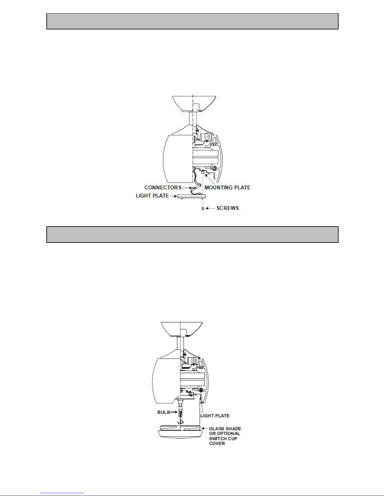
NOTE: Before starting installation, disconnect the power by turning off the circuit breaker or removing the fuse
at fuse box.
1. Remove the 3 screws from the mounting plate.
2. Raise and hold the light plate close to the mounting plate and proceed to do the wire connections. Connect the
white wire connectors from the light plate and fan, follow the same procedure with the black wire connectors.
3. Install and secure the light plate by tightening the 3 screws previously removed.
Fig. 13
WARNING: Shut off the power supply before removing or replacing lamp. In handling of halogen bulb, care should
be taken not to touch it with your bare hands. Oil residue will shorten the life of the halogen bulb. If you accidentally
come into contact, wipe thoroughly with a clean, lint-free, cotton cloth. Allow the bulb to cool off for 10 minutes
before changing the bulb. Use light bulb in accordance with the fan's specification.
TO REDUCE THE RISK OF FIRE DO NOT EXCEED MAXIMUM WATTAGE RATING.
Install 80W R7S halogen bulb (included). (Disregard this step if using the optional switch cup cover) Raise glass
shade or optional switch cup cover up against bottom of fan housing and secure it to fan by turning it clockwise until
snug. DO NOT OVERTIGHTEN.
Note: If installing the optional switch cup cover, make sure is securely tightened.
Fig. 14
INSTALLING THE LIGHT BULB AND GLASSE SHADE
INSTALLING THE LIGHT PLATE
12
FAN WALL CONTROL
Turn on the power and check the operation of the fan.
• OFF Position – fan off
• 3rd Position – low medium fan speed
• 2nd Position – medium fan speed
• 1st Position – high fan speed
Light Control
• Toggle Switch – on/off
Fig. 15
REVERSING SWITCH
Your ceiling can operate either in fan mode or reverse fan mode.
NOTE: to change the direction of the rotation of the blades the fan must not be operating.
The Reverse switch is located on the top of the motor housing. Slide the switch to the left for warm weather
operation. Slide the switch to the right for cool weather operation.
Warm Weather (forward)
A DOWNWARD airflow creates a cooling effect as shown in Figure 16. This allows you to set your air
conditioner on a warmer setting without affecting your comfort.
Cool Weather (Reverse)
An UPWARD airflow moves warmer air off the ceiling area as shown in Figure 17. This allows you to set your
heating unit on a cooler setting without affecting your comfort.
SUMMER OPERATION
WINTER OPERATION
Fig. 16 Fig. 17
USING YOUR CEILING FAN
13
Please note that all ceiling fans are not the same, even in the same model—some may move more or less than
others. Movement of a couple of centimetres is quite acceptable and does not suggest the fan will fall down.
Even though all blades are weighted and grouped by weight, it is impossible to eliminate wobble altogether and
should not be considered a problem. Ceiling fan tend to move during operation because they are not generally
rigidly mounted
You may do the following to reduce wobbling:
1) Check all the blade mounting screws are tight and secure.
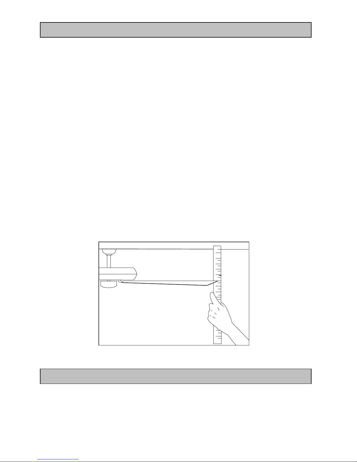
2) Wobbling problems may result from inconsistent blade level. To check blade level, measure the distance
from each blade tip to the ceiling.
Note: If measurements are inconsistent: check blade mount screws are not over tightened or loose
which can cause the blade tips not to be level.
3) Blade tracking may be checked simply by use of a household ruler as shown in the below Figure18.
Place the ruler vertically against the ceiling. Line up the outside edge of one of the blades of the ceiling fan
and note the measurement on the ruler. Turn the blade slowly by hand to check that the other remaining
blades match up to the same point on the ruler. If the blades are not aligned it may mean that a blade may
be out of shape or warped or the screws securing the blades to the motor are not evenly tightened or are
too loose.
Ruler
Measuring
Point
Fig. 18
CARE & CLEANING
Periodic cleaning of your ceiling fan is the only maintenance required. Use a soft brush or lint free cloth to avoid
scratching the paint/plated finish. Please make sure the fan is not operating when cleaning.
Do not use water when cleaning your ceiling fan. It could damage the motor or the blades and create the
possibility of an electrical shock.
BALANCING / WOBBLYING TROUBLE SHOOTING
FAN CARE AND WARRANTY INFORMATION
14
The manufacturer warranty covers actual faults that may develop, but NOT minor complaints, e.g. noise from motor
run—ALL ELECTRIC MOTORS ARE AUDIBLE TO SOME EXTENT.
Ceiling fan tend to move during operation due to the fact that they are not generally rigidly mounted—if they
were, they could generate excessive ceiling vibration and stress on their Mountings.
Movement of a couple of centimetres is quite acceptable and does not suggest the fan will fall down.
Ceiling fans are mounted very securely on steel brackets with rubber cushioning or with ball-joints to allow free
movement.
Please note that all ceiling fans are not the same, even in the same model—some may move more or less
than others.
Threaded components working slighting loose or blade carriers even slightly bent due to vigorous cleaning or
bumping can cause extra wobble and noise. THIS IS NOT COVERED UNDER WARRANTY- but a little care and
maintenance can reduce or prevent this problem.
This is outside the manufacturer’s warranty. If a fan has a fault, it will be noticeable at all times. Naturally, when
everything is quiet at night, you will be more inclined to hear small noises, which may not be noticeable at other
times. Even slight power fluctuations and mains frequency signals superimposed in your electricity supply may
cause a change in fan motor noise, this is normal.
Except for actual fault in manufacture, which are extremely rare. FAN LIGHTS AND GLOBES ARE NOT
COVERED UNDER YOUR FAN WARRANTY. Noises and vibration etc. are often more accentuated when a fan
light is fitted.
For instance a fan light glass that has not been tightened or worked loose can cause a rattle. Again, care and
maintenance will reduce this.
The fan must be installed so that the blades are more than 2.3 meters above the floor.
All electrical connections must be made by a licensed electrician.
All electric motors, including fans make some noise and may feel hot if touched—this is not a fault.
Some fan wobble more than other—even in the same model.
Fan lights can rattle, but are not covered under warranty
Fan wall controller make slight buzz and get warm especially on lower setting.
All these occurrences are not covered by the manufacturer’s warranty.
WARNING
FAN LIGHT
BUMP-IN-THE NIGHT
NORMAL WEAR AND TEAR
WOBBLE
WARRANTY SERVICE
NOTES TO INSTALLERS
15
WARNING: THE CEILING FAN MUST BE SWITCHED OFF, BEFORE ANY TROUBLESHOOTING IS
PERFORMED.
FAN Models
Rated Voltage
Rated power
(motor)
Rated power lamp (for
models with light only)
Lamp type
Artemis F803
220 - 240 VAC
70W
MAX 80W
R7S
TROUBLE
PROBABLE CAUSES
SUGGESTED REMEDY
1. Fan will not start (Warning:
THE ceiling must be switched
OFF, and the assistance of a
licensed electrician maybe
required.)
A. Fuse or circuit breaker blown.
Check main and branch circuit fuses or
circuit breakers.
B. Loose power line connections to
the fan.
Check line wire connections to fan
C. Speed controller not in correct
position.
Check speed controller’s position.
2. Fan Wobbles
(Refer to Wobble section of the
manual for further information.)
A. Fan blades are not horizontal to
ceiling.
Refer to “wobbling fixing” section of
manual.
- The blade may require adjustment
at the blade mounting screws;
- The blade is out of shape, thus
causing wobbling. New blades set
will require to be replaced. Contact
your local Beacon Lighting store.
B. Blade screws are loose.
Make sure all screws are securely
fastened.
C. Blade/s are out of shape
Remove blade and lay on a flat surface to
check if blades are out-of-shape. Contact
agent or manufacturer for replacement
blades.
3. Fan sound noisy
A. Top canopy touching ceiling.
Lower Canopy from ceiling to ensure
minimum 3 mm clearance.
B. Loose fan blade screws.
Re-tighten all screws on fan blades but
never over-tighten.
C. Ceiling fan not secured against
ceiling.
Re-tighten all screws in the hanging
bracket or plate.
D. Incorrect speed controller.
Change the controller to the one supplied.
E. Audible buzzing noise. Cause by
Ripple Control signals. Please refer to
the Ripple Control section of this
manual.
Install a Ripple Control filter. (Refer to the
Ripple control information in this manual.)
4. Mechanical Noise
A. Allow at least for 8 hours settling-in
period.
5. Light will not turn ON
(Optional light kit ONLY)
The globe/lamp has failed.
Replace globe/lamp
TROUBLE-SHOOTING CHECKLIST
SPECIFICATION

16
This product is guaranteed against electrical defects in material or manufacturing workmanship for faults when
under normal domestic/residential conditions for 24 months from the date of purchase.
1. Installation being performed by a qualified licensed Electrician.
This warranty will not apply if the ceiling fan is installed by anyone other than a licensed electrician. Problems
arising from incorrect installation are not covered by warranty.
2. Painted and/or plated finishes of the ceiling fan are only covered under warranty for 6 months.
3. The warranty service does not cover:
a. Repair of defects caused by accident, fire, misuse, alterations modification, negligence, incorrect or
incomplete installation/operation, any unauthorized person attempting to repair the ceiling fan, or acts of
God.
b. Claims or damage to furniture, carpet, wall, ceiling foundations or any other consequential loss either
direct or indirectly resulting from a faulty ceiling fan.
4. The light fitting will be covered by warranty for electrical defect. Breakage of glasses is not covered by
warranty. Lamps are also not covered by warranty. Light fittings can accentuate noises and vibrations, which
can be traced to loose glass or fittings and are not covered by warranty. Notification to your local dealer within
48 hours of installation is required where glasses have found to be broken on unpacking
5. The warranty applies to actual faults which may develop. Minor running noises are not covered. All electrical
motors have some audible noise. Allow at least eight hours of operation to allow the bearings to properly seat.
The fan, especially when set on low, may feel warm to touch – this is not a fault. Fan noises can vary due to
slight power fluctuations and mains frequency signals for off – peak-controlled appliances.
6. Threaded components such as blade nuts can work slightly loose during normal operation. These should be
tightened regularly to ensure the fan doesn’t develop operation noises.
7. Minor variation of speed may be evident between different fans, even in the same model and is not a product
fault and not covered by warranty.
8. Blades are not covered by warranty against defect in material. Notification within 48 hours of installation is
required where blades have found to be broken on unpacking, contact your local dealer who will send you a
new set of blades. Each blade set is balanced so it is important to replace all blades. Blades affected by
climatic conditions and by maintenance are not covered by this warranty.
In the event of service being required, please contact your local dealer
WARRANTY CONDITIONS

17
Herzlichen Glückwunsch zum Kauf Ihres neuen Artemis Deckenventilators von Minka Aire. Es handelt sich
hier um ein besonders hochwertiges Produkt und wir sind uns sicher, dass Sie mit Ihrem Kauf sehr
zufrieden sein werden.
.
1. Für eine erfolgreiche Installation lesen Sie die Anleitung bitte sorgfältig durch und schauen Sie sich die
Abbildungen genau an.
2. Zu Ihrer Sicherheit müssen alle elektrischen Anschlüsse und Abschaltungen von einem konzessionierten
Elektriker durchgeführt werden.
3. Der Montageort für den Ventilator muss eine Tragfähigkeit von mind estens 48 kg aufweisen.
4. Der Ventilator muss geerdet sein.
5. Schließen Sie den Motor des Ventilators nicht an den Dimmerschalter an. Verwenden Sie nur den
mitgelieferten Wandregler.
6. Es wird nicht empfohlen, Deckenventilatoren und Gasgeräte gleichzei tig im selben Raum zu betreiben.
7. Um Schäden zu vermeiden, muss der Ventilator abgeschaltet werden und vollständig zum Stillstand kommen,
bevor die Laufrichtung geändert wird.
8. Sobald der Ventilator vollständig installiert ist, stellen Sie sicher, dass a lle Verbindungen gesichert und auf
festen Sitz überprüft sind, um mögliche Probleme zu vermeiden.
9. Durch die natürliche Bewegung des Ventilators kann es vorkommen, dass Verbindungen sich lösen.
Überprüfen Sie die Befestigungsverbindungen, Halterungen un d Flügelblätterteile zweimal jährlich auf festen
Sitz.
Hinweis: Die in dieser Anleitung dargestellten Sicherheitsmaßnahmen und –anleitungen können nicht alle
möglichen Zustände und Situationen abdecken, die potentiell auftauchen können. Es muss grundsätzli ch davon
ausgegangen werden, dass gesunder Menschenverstand, Vorsicht und Sorgfalt Faktoren darstellen, die in kein
Produkt eingebaut werden können.
WICHTIGE HINWEISE
STEUERUNG DESVENTILATORS
Ihre Garantie erlischt, wenn anderer als der mitgelieferte Wandregler verwendet wird. Verwenden Sie daher
AUSSCHLIEßLICH den mitgelieferten Wandregler.
INSTALLATION DES VENTILATORS
Dieser Deckenventilator darf nach unseren Garantiebedingungen nur durch einen konzessionierten Elektriker
installiert werden. Dieser Ventilator ist ausschließlich für den Betrieb im Innenbereich konstruiert worden. Die
Montage an Orten, an denen der Ventilator Wasser oder Feuchtigkeit ausgesetzt ist, kann gefährlich sein und führt
zum Erlöschen der Garantie.
SICHERHEITSMAßNAHMEN

18
FEHLERSUCHE
Schauen Sie immer in der „Checkliste zur Fehlerbehebung“ nach, die in dieser Broschüre enthalten ist.
BEI DER INSTALLATION KÖNNEN MECHANISCHE GERÄUSCHE AUFTRETEN. GEBEN SIE IHREM
DECKENVENTILATOR MINDESTENS 8 STUNDEN EINLAUFZEIT. MANCHE VENTILATOREN SCHWINGEN
MEHR ALS ANDERE – AUCH INNERHALB DESSELBEN MODELLS; DAS IST KEIN ANZEICHEN DAFÜR,
DASS DER VENTILATOR DEFEKT IST.
PACKUNGSINHALT
Packen Sie Ihren Ventilator aus und überprüfen Sie den Inhalt. Die folgenden Teile sollten enthalten sein:
1. Flügelblätter 3 x
2. Aufhängevorrichtung 1 x
3. Baldachin 1 x
4. Baldachinabdeckung 1 x
5. a. Standard-Hängestangenkit 1 x
5. b. Kürzeste Hängestange (nur für Montage mit
wenig Abstand zur Decke) 1 x
6. Abdeckung Verbindungsstück 1 x
7. Motor des Ventilators/Gehäuseeinheit 1 x
8. Befestigungsplatte Leuchteinheit 1 x
9. Leuchtplatte 1 x
10. Glasabdeckung 1 x
11. Optionale Metallabdeckung 1 x
12. 80W R7S Halogenlampe 1 x
13. Wandregler inkl. 2 Befestigungsschrauben
14. Holzschraube 10 x 38 mm 2 x
15. Maschinenschraube 8 x 19 mm 2 x
16. Befestigungsscheibe 2 x
17. Sternscheibe 4 mm 2 x
18. Scheibe 2 x
19. Schraube 4,8 mm x 17 mm 10 x
20. Unterlegscheibe 10 x
19
BENÖTIGTES WERKZEUG
Benötigtes Werkzeug:
- Phillips / Schlitzschraubendreher
- Zange
- Engländer
- Stehleiter
- Drahtschneider
AUFHÄNGEVORRICHTUNG MONTIEREN
Der Ventilator muss so angebracht werden, dass der Abstand zwischen den Flügelblättern und dem Boden
mindestens 2,3 m und zwischen den Flügelblätterspitzen und dem nächsten Objekt bzw. den Wänden 30 cm
beträgt.
Befestigen Sie die Hängevorrichtung am Deckenbalken bzw. an der Deckenkonstruktion, die eine Tragkraft von
mindestens 48 kg haben müssen, mit den beiden mitgelieferten langen Schrauben. Stellen Sie sicher, dass
mindestens 30 mm der Schrauben in das Halteelement eingedreht sind.
BALKEN MUSS EINE TRAGKRAFT
VON MINDESTENS 48 KG
HABEN
Abb. 1
ANMERKUNG: DIESE ABBILDUNG DIENT NUR
ANSCHAUUNGSZWECKEN UND STELLT NICHT DIE
EIGENTLICHE HALTEVORRICHTUNG DAR.
ANMERKUNG: Die mitgelieferten Schrauben für die Haltevorrichtun g sind ausschließlich für Holzkonstruktionen
geeignet. Für alle anderen Materialien MÜSSEN die entsprechend passenden Schrauben benutzt werden.
20
VENTILATOR AUFHÄNGEN
Lockern Sie die Schraube in der Klemmleiste und entfernen Sie die Klemmleiste bis zur späteren Verwendung.
Befestigen Sie mit den mitgelieferten Schrauben die Aufhängevorrichtung an dem Deckenbalken bzw. an der
Deckenkonstruktion. Befestigen Sie die Klemmleiste wieder an der Aufhängevorrichtung.
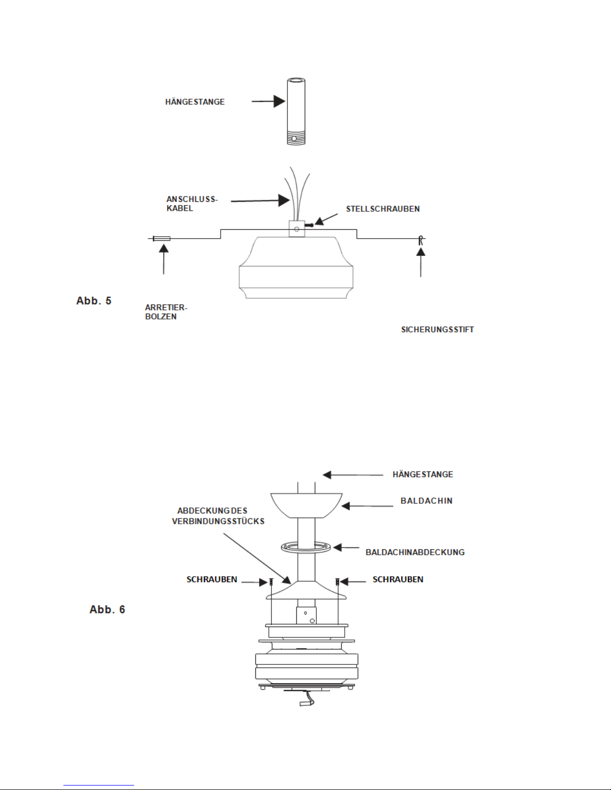
Lockern Sie die zwei Stellschrauben und entfernen Sie den Sicherheitsstift und den Arretierbolzen von
dem oberen Verbindungsstück der Motoreinheit.
Schrauben Sie die Aufhängekugel von der Hängestange ab, indem Sie die Stellschraube lösen, den
Querstift entfernen und die Kugel von der Stange schieben.
21
Führen Sie die Ventilatordrähte vorsichtig durch die Hängestange und drehen Sie anschließend die Stange in das
Verbindungsstück ein. Bringen Sie die Löcher übereinander und setzen Sie den Arretierbolzen und den
Sicherungsstift wieder ein. Ziehen Sie die Stellschrauben an.
Streifen Sie die Abdeckungen des Verbindungsstücks und des Baldachins und den Baldachin selbst über das
Hängerohr. Führen Sie zwei Schrauben in die Abdeckung des Verbindungsstücks ein und befestigen Sie es,
indem Sie die Schrauben anziehen. Bringen Sie nun vorsichtig die Aufhängekugel wieder über die Stange und
stellen Sie sicher, dass der Querstift sich dabei in der richtigen Position befindet. Überzeugen Sie sich davon,
dass die Schrauben fest sitzen und dass Drähte nicht verd reht sind.
22
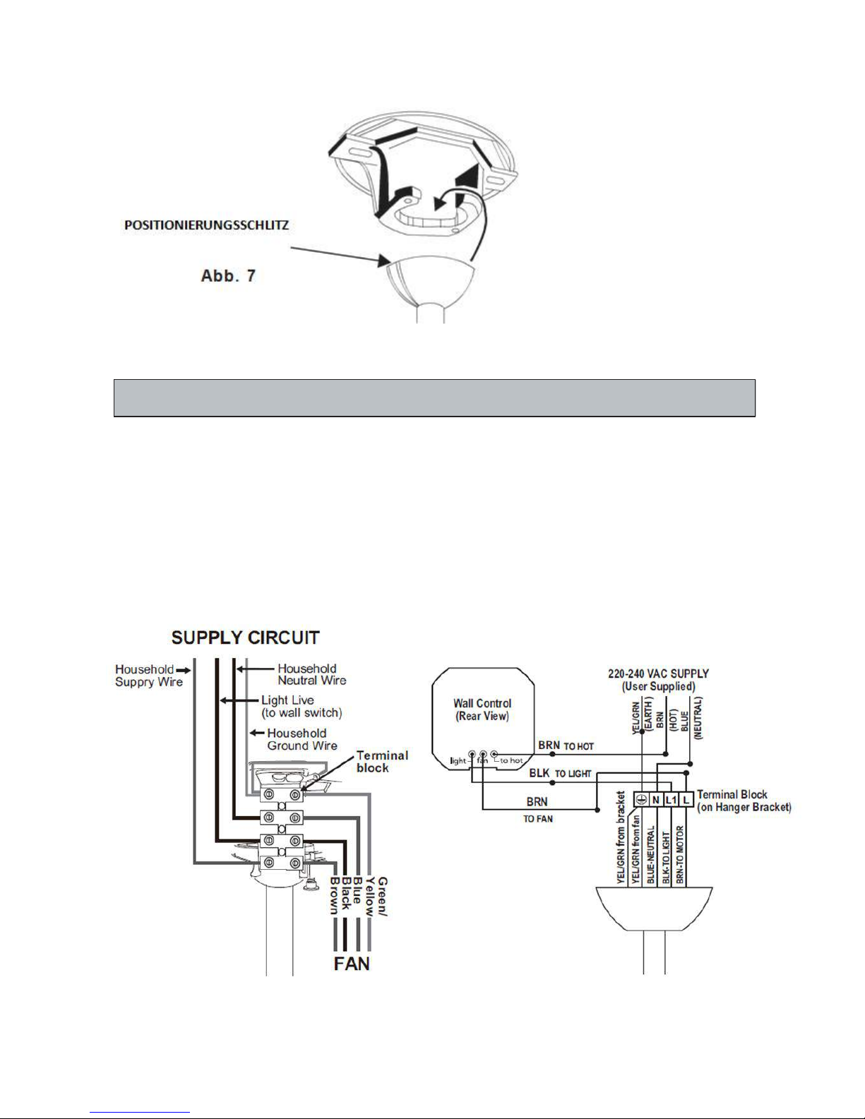
Heben Sie nun die Motoreinheit in Position und fügen Sie die Aufhängekugel in die Aufhängevorrichtung ein.
Drehen Sie nun, bis die Aufhängekugel fest in den Positionierungsschlitz einrastet. Bei korrektem Einsetzen
dürfte die Stange sich jetzt nicht mehr drehen.
ELEKTRISCHER SCHALTPLAN
WARNHINWEIS: ZU IHRER SICHERHEIT MÜSSEN ALLE ELEKTRONISCHEN VERBINDUNGEN VON EINEM
KONZESSIONIERTEN ELEKTRIKER DURCHGEFÜHRT WERDEN.
HINWEIS: IN DER FESTVERDRAHTUNG MUSS EIN ALLPOLIGER TRENNSCHALTER VORHANDEN SEIN.
Verbinden Sie die Anschlüsse wie folgt:
Abb.8
23
English
German
FAN
VENTILATOR
Wall Control
Wandregler
(Rear View)
(Rückansicht)
220-240 VAC SUPPLY
220 – 240 VAC NETZSPANNUNG
(User Supplied)
(benutzerseitig)
YEL/GRN (EARTH)
GELB/GRÜN (SCHUTZLEITER – ERDE)
BRN (HOT)
BRAUN (PHASE)
BLUE (NEUTRAL)
BLAU (NEUTRAL)
BRN TO HOT
BRAUN ZU PHASE
BLK TO LIGHT
SCHWARZ ZU LICHT
BRN TO FAN
BRAUN ZU VENTILATOR
YEL/GRN (EARTH)
GELB/GRÜN (SCHUTZLEITER - ERDE)
YEL/GRN from bracket
GELB/GRÜN von Aufhängevorrichtung
YEL/GRN from fan
GELB/GRÜN vom Ventilator
BLUE – NEUTRAL
BLAU – NEUTRAL
BLK – TO LIGHT
SCHWARZ ZU LICHT
BRN TO MOTOR
BRAUN ZU MOTOR
Terminal Block (on Hanger Bracket)
Klemmleiste(an Aufhängevorrichtung)
light
Licht
fan
Ventilator
to hot
zu Phase
N N L1
L1
L
L
Verstauen Sie die Drahtverbindungen sorgfältig in dem Gehäuse bzw. in der Wandöffnung, wenn kein Gehäuse
verwendet wird. Verwenden Sie für die Befestigung des Wandschalters und der Abdeckung an dem Gehäuse bzw .
an der Abdeckung nur die mitgelieferten Schrauben.
English
German
WALL PLATE
ABDECKUNG
SCREWS
SCHRAUBEN
SWITCH
SCHALTER
OUTLET BOX
GEHÄUSE
HINWEIS: Die Ausgangsdose ist nicht Teil der Lieferung. Sie kann separat über einen Elektriker bezogen
werden.
24
1. Entfernen Sie 1 der 2 Schrauben von der Unterseite der Aufhängevorrichtung und lockern Sie die andere um
eine halbe Schraubkopfdrehung.
2. Schieben Sie den Baldachin über die Aufhängevorrichtung und bringen Sie das Stichloch des Baldachins
über die Schraube der Aufhängevorrichtung. Drehen Sie den Baldachin, bis er an der schmalen Seite des
Stichloches einrastet.
3. Richten Sie das runde Loch des Baldachins mit dem verbleibenden Loch an der Aufhängevo rrichtung aus
und ziehen Sie die beiden Schrauben fest an
.
HINWEIS: Ziehen Sie die Baldachinschrauben so lange an, bis der Baldachin und die Baldachinabdeckung fest
sitzen.
ENDMONTAGE
25
1. Richten Sie die oberen Löcher eines Flügelblatte s an der einer oberen Flügelblatthalterungen aus und lassen
Sie sie einrasten. Führen Sie nun vorsichtig die unteren Löcher des Flügelblattes zu den Löchern der unteren
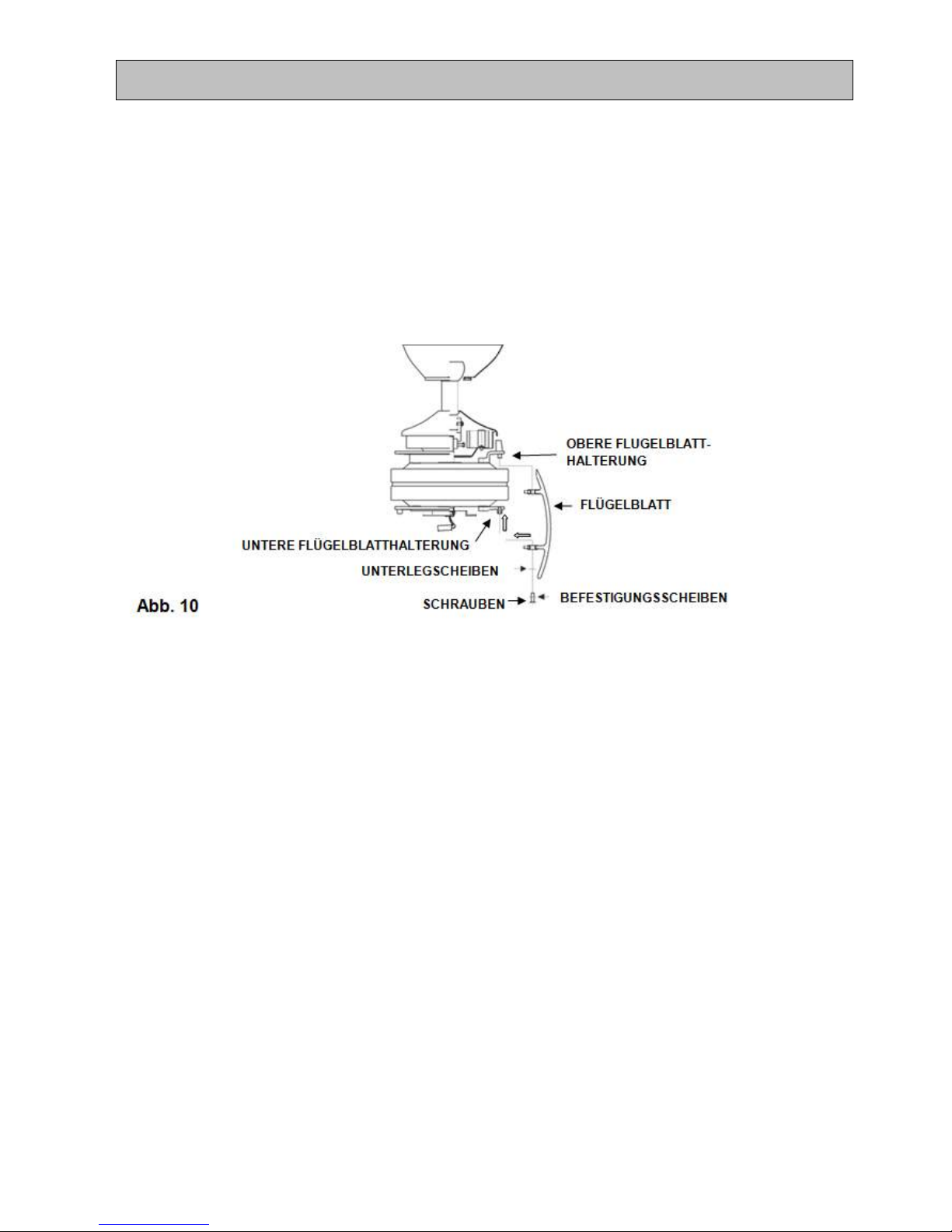
Flügelblatthalterung. Befestigen Sie das Flügelblatt mit den mitgelieferten 3 Schrauben ,
Befestigungsscheiben und Unterlegscheiben. Verfahren Sie mit den verbleibenden zwei Flügelblättern
ebenso.
2.
Alle Flügelblättersets werden nach Gewicht zusammengestellt. Kunststoff kann jedoch verschiedene
Dichtegrade aufweisen. Daher kann es vorkommen, dass der Ventilator trotz Gewichtsabstimmung leicht
schwingt
HINWEIS: Befestigen Sie die Flügelblätter erst am Motorengehäuse, wenn der Motor bereits an der Decke
montiert wurde. Wenn Sie mehr als einen Ventilator installieren, stellen Sie sicher, dass die Flügelblättersets nicht
durcheinander geraten, da jedes Set dynamisch ausgewuchtet ist
MONTAGE DER FLÜGELBLÄTTER
26
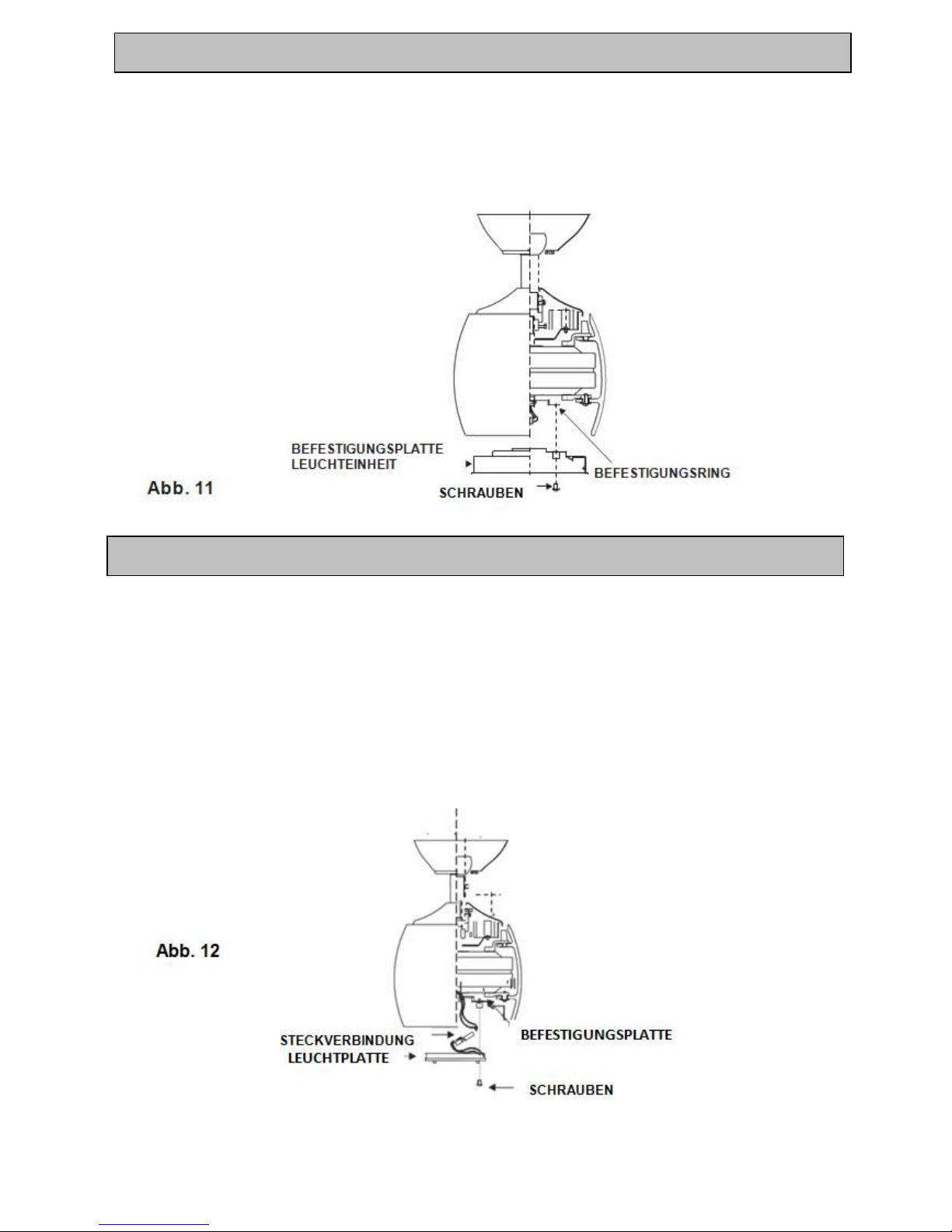
1. Entfernen Sie 3 Schrauben von dem Befestigungsring.
2. Setzen Sie die Befestigungsplatte für die Leuchteinheit auf den Befestigungsring. Setz en Sie die zuvor
entfernten 3 Schrauben wieder ein und ziehen Sie sie an.
HINWEIS: Trennen Sie vor der Installation die Stromverbindung, indem Sie den Leitungsschutzschalter
ausschalten oder die Sicherung aus dem Sicherungskasten entfernen.
1. Entfernen Sie 3 Schrauben von der Befestigungsplatte.
2. Heben Sie die Leuchtplatte an und halten Sie sie nahe an die Befestigungsplatte. Nehmen Sie nun die
Verdrahtung vor. Verbinden Sie die weißen Drähte der Leuchtplatte und des Ventilato rs miteinander und
wiederholen Sie den Vorgang mit den schwarzen Drähten.
3. Installieren und sichern Sie die Leuchtplatte, in dem sie die zuvor entfernten Schrauben wieder anziehen
INSTALLATION DER LEUCHTPLATTE
MONTAGE DER BEFESTIGUNGSPLATTE FÜR DIE LEUCHTEINHEIT
27
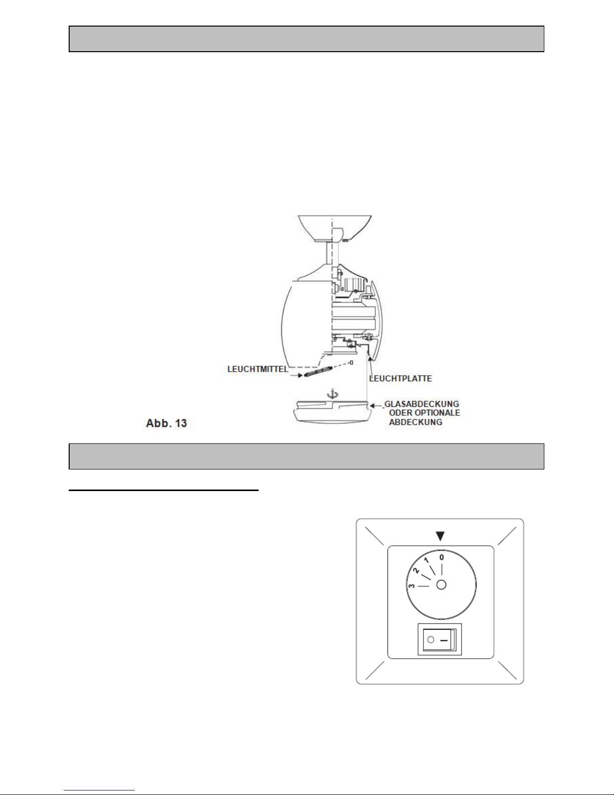
WARNHINWEIS: Schalten Sie die Stromzufuhr ab, bevor Sie das Leuchtmittel entfernen bzw. austauschen. Beim
Umgang mit der Halogenlampe ist Vorsicht geboten. Sie sollte nicht mit bloßen Händen berüht werden.
Ölrückstände verkürzen die Lebensdauer der Halogenlampe. Sollten Sie die Lampe versehentlich b erühren,
wischen Sie sie gründlich mit einem sauberen fusselfreien Baumwolltuch ab. Lassen Sie das Leuchtmittel vor
dem Austausch 10 Minuten lang abkühlen. Verwenden Sie nur die Leuchtmittel, die in den technischen Daten für
den Ventilator aufgeführt sind. UM DIE BRANDGEFAHR ZU VERRINGERN, DARF DIE MAXIMALE
NENNLEISTUNG NICHT ÜBERSCHRITTEN WERDEN.
Installieren Sie die (mitgelieferte) 80 W R7S Halogenlampe. (Lassen Sie diesen Schritt außer Acht, wenn Sie die
optionale Abdeckung verwenden). Heben Sie die Glasabdeckung oder die optionale Abdeckung an die Unterseite
des Ventilatorgehäuses und befestigen Sie diese an dem Ventilator, indem Sie sie in Uhrzeigerrichtung drehen,
bis sie fest sitzen. NICHT ÜBERDREHEN.
HINWEIS: Wenn Sie die optionale Metallabdeckung verwenden, stellen Sie sicher, dass diese fest angezogen ist.
WANDREGLER DES VENTILATORS
Schalten Sie den Storm ein und überprüfen Sie den Betrieb des Ventilators.
• OFF Position – Ventilator ist ausgeschaltet
• 3. Position – niedrige Ventilatordrehzahl
• 2. Position – mittlere Ventilatordrehzahl
• 1. Position – hohe Ventilatordrehzahl
Lichtsteuerung
• Kippschalter – on/off (ein/aus)
Abb. 14
BETRIEB DES DECKENVENTILATORS
EINSETZEN VON LEUCHTMITTEL & GLASSABDECKUNG
 Loading...