

Page 1

MINIXTM 7025-UC3
User's Manual
Rev: 1.0, December 2010
Website: http://www.jwele.com
Mini-ITX Motherboard
Page 2

Disclaimer
The intellectual property of this manual belongs to our company. The ownership of all of the
products, including accessories and software etc. belong to our company. No one is permitted to
copy, change, or translate without our written permission.
We compiled this manual based on our careful attitude, but we can not guarantee the accuracy of
the contents. This manual is purely technical documentation, without any hint or other meanings,
and we won't commit users' misunderstanding of the typesetting error.
Our products are in continuous improvement and updating, Therefore, we retain the right that we
won't give notice to the users in future.
Copyright
All of the trademark in this manual belong to their own registered company.
All of the products name is only for identification, its title belongs to its manufacturer or brand
owner.
Page 3

Table of Contents
Chapter 1 Introduction ............................................................................................ 4
1.1 Package Checklist ................................................................................................................ 4
1.2 Specications ......................................................................................................................5
1.3 Mainboard Layout ................................................................................................................6
1.4 Connecting Rear Panel I/O Devices ....................................................................................... 7
Chapter 2 Hardware Setup ....................................................................................... 8
2.1 Choosing a Computer Chassis ...............................................................................................8
2.2 Installing Mainboard ............................................................................................................ 8
2.3 Installing CPU and CPU Cooler...............................................................................................9
2.4 Installation of Memory Modules .......................................................................................... 10
2.5 Connecting Peripheral Devices ............................................................................................ 11
2.5.1 Serial ATA Connectors .................................................................................................. 11
2.5.2 PCIE slot ..................................................................................................................... 11
Chapter 3 Jumpers & Headers Setup .......................................................................12
Chapter 4 BIOS Setup Utility ...................................................................................17
4.1 About BIOS Setup ..............................................................................................................17
4.2 To Run BIOS Setup ............................................................................................................ 17
4.3 About CMOS ......................................................................................................................17
4.4 The POST (Power On Self Test) ..........................................................................................17
4.5 BIOS Setup — CMOS Setup Utility .......................................................................................18
4.5.1 CMOS Setup Utility .......................................................................................................18
4.5.2 Control Keys ................................................................................................................19
4.5.3 Main Menu .................................................................................................................. 20
4.5.4 Advanced Setting .........................................................................................................22
4.5.5 Boot Setting ................................................................................................................ 29
4.5.6 Security Setting ........................................................................................................... 31
4.5.7 Power Setting .............................................................................................................. 32
4.5.8 JUSTw00T! .................................................................................................................. 35
4.5.9 Exit Setting .................................................................................................................39
Chapter 5 Driver Installation ...................................................................................42
Page 4

MINIX
7025-UC3 User's Manual
Chapter 1 Introduction
1.1 Package Checklist
Thank you for choosing our product.
Please check the following packing and accessories, if there is any broken or part missing,
please contact with your franchiser.
• Rear I/O Panel X 1
• User's Manual X 1
• Driver/Utility CD X 1
• Serial ATA Signal Cable X 2
• Serial ATA Power Cable X 2
The items listed above are for reference only, and are subject to change without notice.
- 4 -
Page 5

MINIX 7025-UC3 User's Manual
1.2 Specications
CPU
Main Chipset - Integrated GeForce
Main Memory
BIOS
Rear Panel I/O
Internal I/O
Connectors
Sound
Onboard LAN - Onboard 10/100/1000Mbps compatible LAN (Optional)
Expansion Slots - 1 x PCIE slot
Form Factor Mini ITX (170mm*170mm)
- Support AMD(R) Socket AM3 processors
- AMD Phenom™ II x4/ Phenom™ II x3/ Phenom™ II x2/ Athlon™ II x4/
Athlon™II x3/Athlon™ II x2/ Sempron™ 1xx processors
- Support 2x1.5V DDR3 DIMM socket supporting up to 8GB of system memory
- Support for DDR3 1066/1333/1600(OC)MHz memory modules
- AMI BIOS, supports Plug&Play
- Supports Advanced Power Management ACPI,STR
- CPU temperature, Fan speed, System Voltage monitoring
- 1 x PS/2 Keyboard port
- 1 x PS/2 Mouse port
- 1 x VGA port
- 1 x COM port
- 1 x RJ45 port
- 4 x USB 2.0 ports
3 x Audio jacks (Line In / Line Out / MIC In)
-
- 1 x 20-pin ATX main power connector
- 1 x 4-pin ATX 12V power connector
- 4 x SATA 3Gb/s connectors
- 2 x System fan headers
- 1 x CPU FAN header
- 1 x Front panel header
- 1 x Front panel audio header
- 1 x SPDIF_OUT header
- 1 x SPEAK header
- 2 x USB 2.0 headers for additional 4 USB 2.0 ports (by cables)
- Onboard 6-channel HD Audio Codec
- Front Panel Jumper, provides stereo MIC port on front panel
®
7025 & nForce® 630a MCP
- 5 -
Page 6
USB
USB LA N1_
AUDIO
PCIE1
F AUDI O_
FP
ANEL
JSPDIF
SPEAK
JBAT
SATA1
SATA2
FUSB
1
FUSB2
SFAN2
PWR12V
CFAN
JC61D3ITX01 V1 0
170 170.*
SATA3
SATA4
PS 2
3
JLPC
VG
A
COM1
SFAN1
B T1
MINIX
7025-UC3 User's Manual
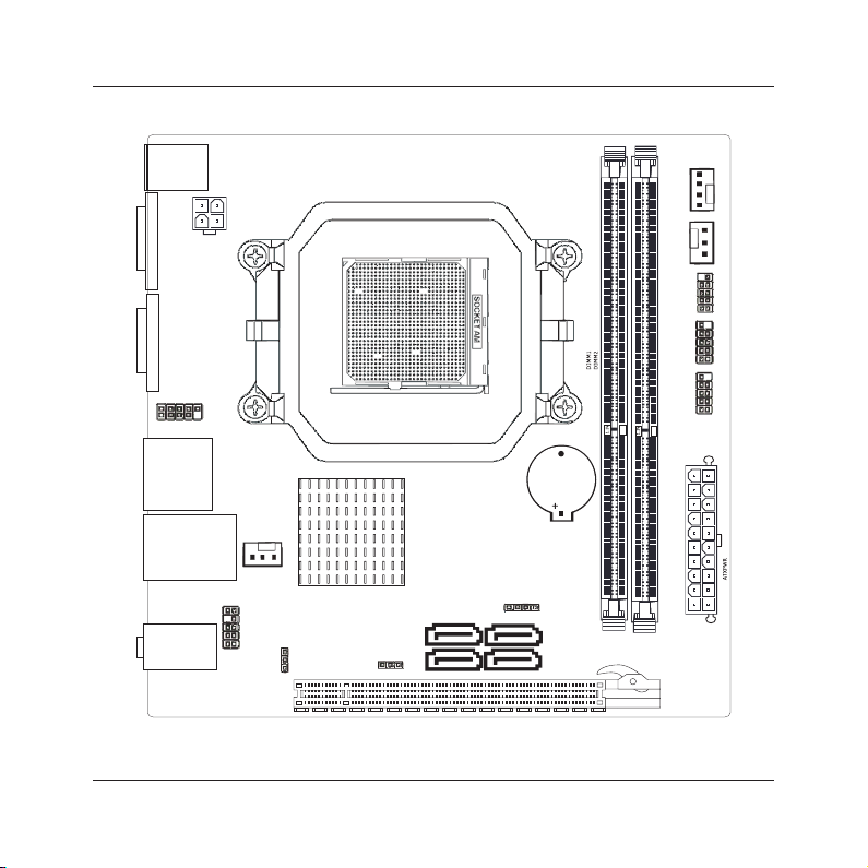
1.3 Mainboard Layout
(This picture is only for reference)
- 6 -
Page 7
PS 2 M ouse
PS 2 K eyboa rd
MINIX
7025-UC3 User's Manual
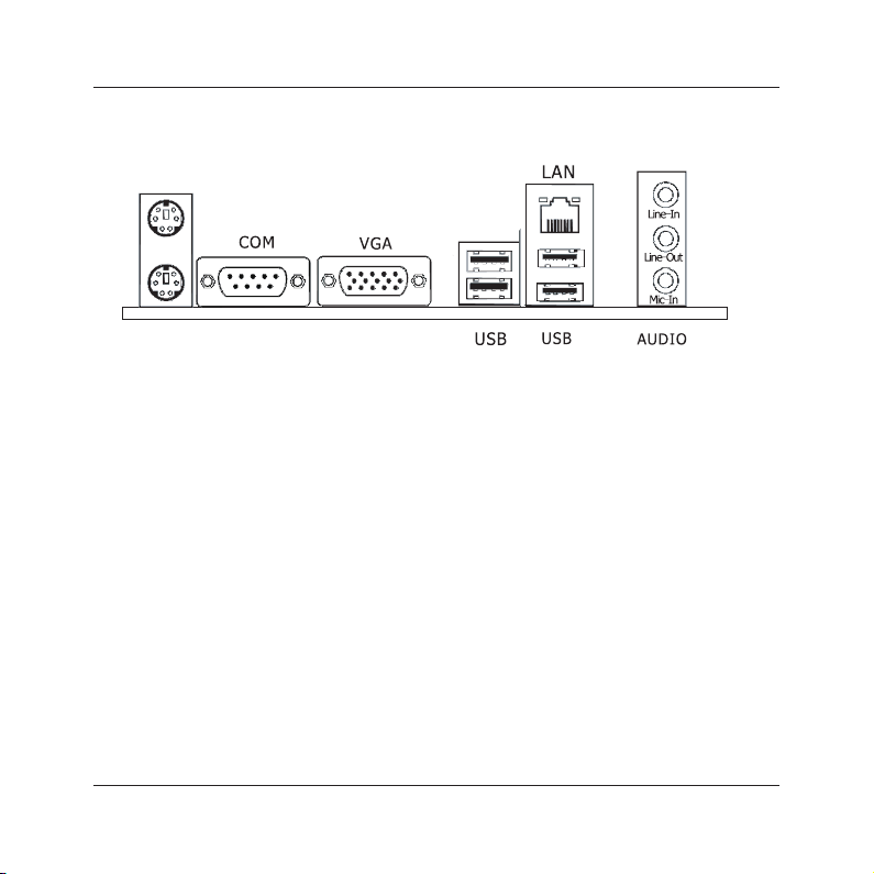
1.4 Connecting Rear Panel I/O Devices
The rear I/O part of these mainboard provides the following I/O ports:
• PS/2 Mouse: Connects to a PS/2 mouse.
• PS/2 Keyboard: Connects to a PS/2 keyboard.
• COM: Connect to external modem.mouse or other devices that support this communication
portocol.
keyboard, mouse, hub, digital camera, joystick, etc.
a network hub.
• AUDIO(Rear Panel Audio):
Line-in (Light Blue): This jack is used to connect to the line out from any external audio
sources such as MP3 player, CD player, AM/FM radio tuner, etc.
Line-out (Front Left/Right Jack, Lime): This jack is used to connect to the front left and
right channel speakers of the audio system.
Mic-in (Pink): This jack is used to connect an external microphone.
(This picture is only for reference)
• VGA: Connects to a monitor's VGA input.
• USB: The USB ports are used to connect USB 2.0/1.1 devices such as scanner, speakers,
• LAN: The LAN port allows the motherboard to connect to a local area network by means of
- 7 -
Page 8
MINIX
7025-UC3 User's Manual
Chapter 2 Hardware Setup
2.1 Choosing a Computer Chassis
• Choose a chassis big enough to install this mainboard.
• As some features for this mainboard are implemented by cabling connectors on the mainboard
to indicators and switches or buttons on the chassis, make sure your chassis supports all the
features required.
• If there is possibility of adopting some more hard drives, make sure your chassis has sufcient
power and space for them.
• Most chassis have alternatives for I/O shield located at the rear panel. Make sure the I/O shield
of the chassis matches the I/O port conguration of this mainboard. You can nd an I/O shield
specically designed for this mainboard in its package.
2.2 Installing Mainboard
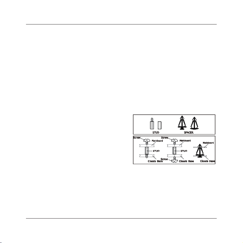
Most computer chassis have a base with many mounting holes to allow the mainboard to be
securely attached, and at the same time, prevent
the system from short circuits. There are two ways
to attach the mainboard to the chassis base:
(1)with studs, or (2) with spacers.
Basically, the best way to attach the board is with
studs. Only if you are unable to do this should you
attach the board with spacers. Line up the holes on
the board with the mounting holes on the chassis.
If the holes line up and there are screw holes, you
can attach the board with studs. If the holes line
up and there are only slots, you can only attach with
spacers. Take the tip of the spacers and insert them into the slots. After doing this to all the slots,
you can slide the board into position aligned with slots. After the board has been positioned,
check to make sure everything is OK before putting the chassis back on.
To install this mainboard:
1. Locate all the screw holes on the mainboard and the chassis base.
2. Place all the studs or spacers needed on the chassis base and have them tightened.
3. Face the mainboard’s I/O ports toward the chassis’s rear panel.
4. Line up all the mainboard’s screw holes with those studs or spacers on the chassis.
5. Install the mainboard with screws and have them tightened.
- 8 -
Page 9
MINIX
7025-UC3 User's Manual
2.3 Installation of the CPU and CPU Cooler
Before installing the CPU, please comply with the following conditions:
1. Please make sure that the mainboard supports the CPU.
2. Please take note of the one indented corner of the CPU. If you install the CPU in the wrong
direction, the CPU will not insert properly. If this occurs, please change the insert direction of
the CPU.
3. Please add an even layer of heat sink paste between the CPU and CPU cooler.
4. Please make sure the CPU cooler is installed on the CPU prior to system use, otherwise
overheating and permanent damage of the CPU may occur.
5. Please set the CPU host frequency in accordance with the processor specications. It is not
recommended that the system bus frequency be set beyond hardware specications since it
does not meet the required standards for the peripherals. If you wish to set the frequency
beyond the proper specications, please do so according to your hardware specications
including the CPU, graphics card, memory, hard drive, etc.
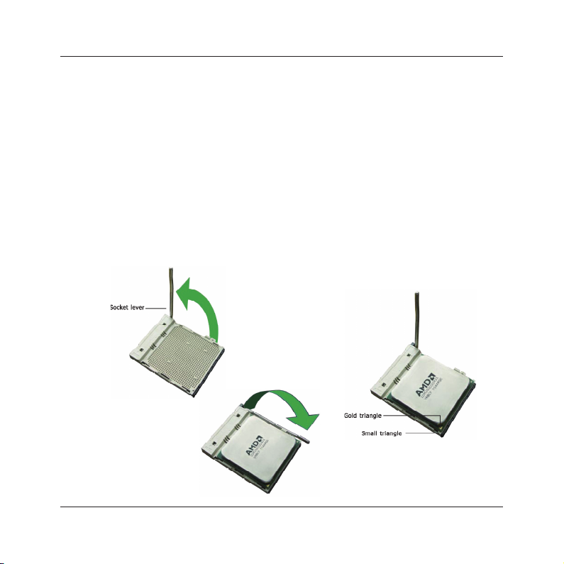
2.3.1 Installation of the CPU
1. Unlock the socket by pressing the
lever sideways, then lift it up to a 90o.
Figure 1
4. When the CPU is in
place, push down the
socket lever to secure
the CPU.
The lever clicks on the
side tab to indicate that
it is locked.
Figure 3
2. Position the CPU above the socket such that
the CPU corner with the gold triangle matches
the socket corner with a small triangle.
3. Carefully insert the CPU into the socket until it
ts place.
Figure 2
- 9 -
Page 10
MINIX
7025-UC3 User's Manual
2.3.2 Installation of the CPU Cooler
For proper installation, please kindly refer to the instruction manuals of your CPU Cooler.
2.4 Installation of Memory Modules
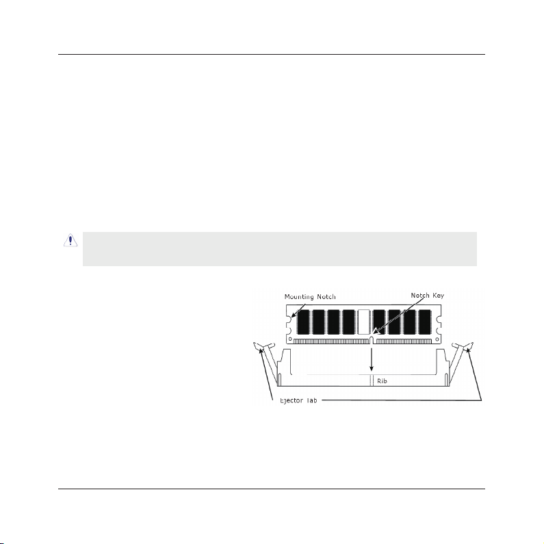
This mainboard provides two 1.5v DDR3 DIMM slots, which supports dual channel memory
technology. To activate the dual channel conguration, you need to install two identical
(same brand, speed, size and chip-type) memory modules into these DIMM slots. Otherwise
the memory will only operate at single channel mode.
For dual channel DDR3 installation:
Populate two DDR3 DIMM modules of the same type and size into slots [DIMM1] + [DIMM2].
Static electricity can damage the electronic components of the computer or optional boards.
Before starting these procedures, ensure that you are discharged of static electricity by
touching a grounded metal object briey.
To install system memory:
1. Power off the computer and unplug the
AC power cord before installing or
removing memory modules.
2. Locate the DIMM slot on the board.
3. Hold two edges of the DIMM module
carefully, keep away from touching its
connectors.
4. Align the notch key on the module with
the rib on the slot.
5. Firmly press the module into the slots until the ejector tabs at both sides of the slot
automatically snap into the mounting notch. Do not force the DIMM module in with extra
force as the DIMM module only ts in one direction.
6. To remove the DIMM modules, push the two ejector tabs on the slot outward
simultaneously, and then pull out the DIMM module.
- 10 -
Page 11
USB
USB LAN1_
AUDIO
PCIE1
F AUDIO_
FP
ANEL
JSPDIF
SPEAK
JBAT
SATA1
SATA2
FUSB
1
FUSB2
SFAN2
PWR12V
CFAN
JC61D3ITX01V 1 0
170170.*
SATA3
SATA4
PS 2
3
JLPC
VG
A
COM1
SFAN1
BT1
MINIX
7025-UC3 User's Manual
2.5 Connecting Peripheral Devices
2.5.1 Serial ATA Connectors
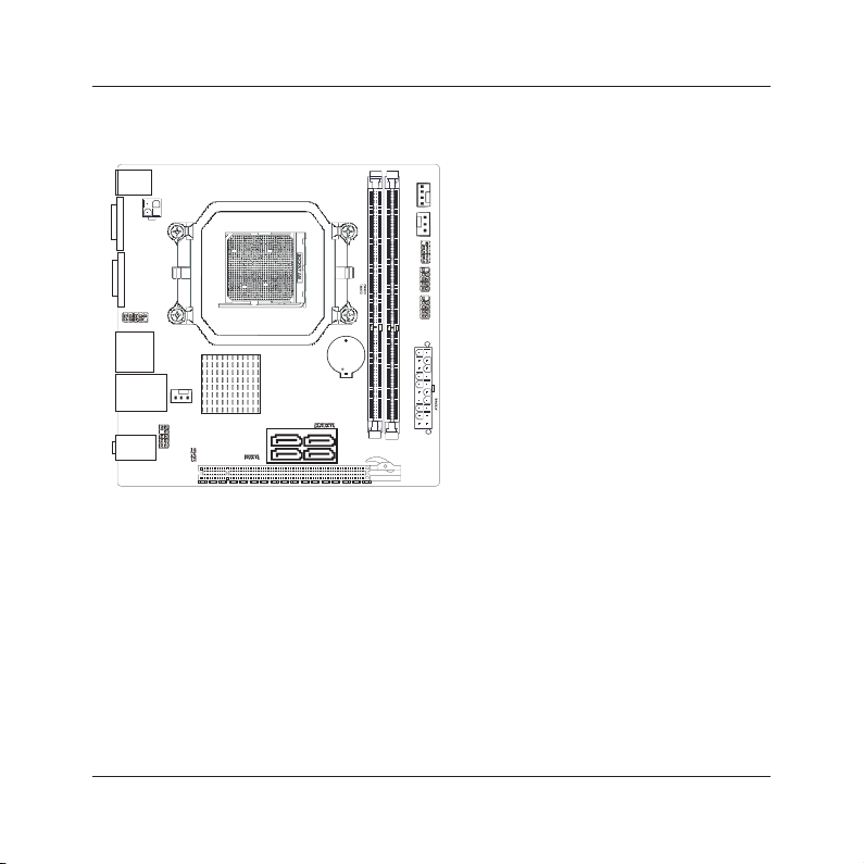
Each SATA connector serves as one single channel to connect one SATA device by SATA cable.
2.5.2 PCIE slot
Install PCIE card into slot “PCIE1” .
- 11 -
Page 12
3
USB
USB LAN1_
AUDIO
PCIE1
F AUDIO_
FP
ANEL
SPEAK
JBAT
SATA1
SATA2
FUSB
1
FUSB2
SFAN2
PWR12V
CFAN
JC61D3ITX01 V1 0
170170.*
SATA3
SATA4
PS 2
JLPC
VGA
COM1
SFAN1
BT1
1
2
3
4
5
6
7
8
9
10
11
12
JSPDIF
MINIX
7025-UC3 User's Manual
Chapter 3 Jumpers & Headers Setup
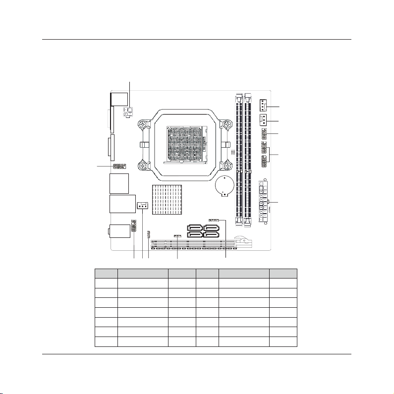
Quick Components Guide
NO. Layout Page NO. No. Layout Page NO.
1 F_AUDIO
2 SFAN2
3 JSPDIF
4 JBAT
5 SPEAK
6 ATXPWR
7 FUSB1/FUSB2
13
13
14
14
14
15
15
8 FPANEL
9 SFAN1
10 CFAN
11 PWR12V
12 JLPC
- 12 -
14
13
16
15
16
Page 13
1 2
910
F AU DI O_
MINIX
7025-UC3 User's Manual
Checking Jumper Settings
• For a 2-pin jumper, plug the jumper cap on both pins will make it CLOSE (SHORT). Remove the
jumper cap, or plug it on either pin (reserved for future use) will leave it at OPEN position.
• For 3-pin jumper, pin 1~2 or pin 2~3 can be shorted by plugging the jumper cap in.
How to identify the PIN1 jumpers?
Please check the mainboard carefully, the PIN1 is marked by "1" or white thick line.
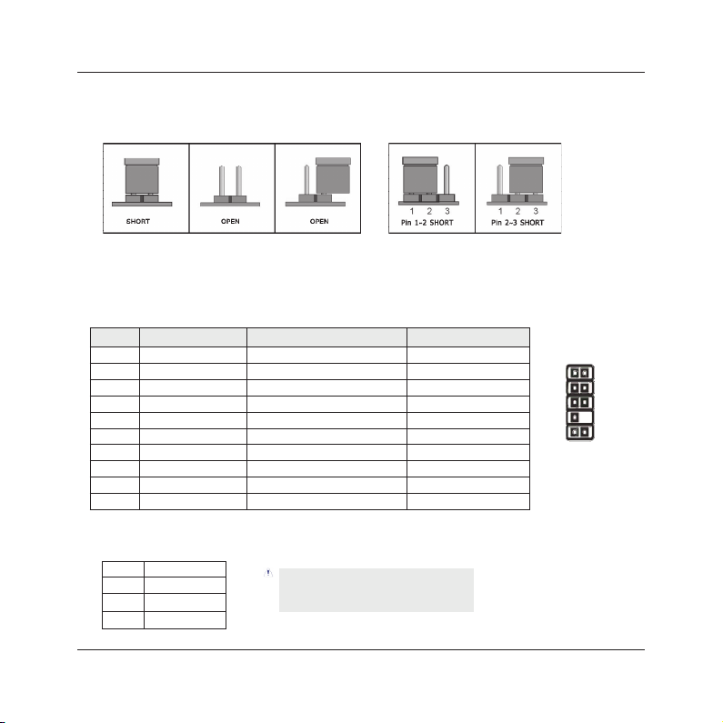
1-F_AUDIO(Front Panel Audio Connection Header)
Pin No. Header HD Audio Denition AC97 Audio Denition
1 PORT1L Microphone_Left Microphone
2 AGND Ground Ground
3 PORT1R Microphone_Right MIC Power
4 PRESENCE# -ACZ_DET N/A
5 PORT2R Line2_Right Line out (R)
6 SENSE1_RETURN AuD_R_Return N/A
7 SENSE_SEND FAUDIO_JD N/A
8 No Pin N/A N/A
9 PORT2L Line2_Left Line Out(L)
10 SENSE2_RETURN AuD_L_Return N/A
2/9-SFAN1/SFAN2(Fan Power Connectors Header)
SFAN1:System fan connectors
Pin No. Denition
1 GND
2 +12V
3 RPM
These fan connectors are not jumpers.
DO NOT plac e jumpe r ca ps on these
connectors.
- 13 -
Page 14
+
-
+
-
PWR LED_
PWR ON_
HD LED_
RST
1
VC C
NC
OU T
GN D
MINIX
7025-UC3 User's Manual
3-S/PDIF Output Connection Header
S/PDIF (Sony/Philips Digital Interface) is a standard audio transfer le format.
It is usually found on digital audio equipment such as a DAT (Digital Audio
Tape) machine or audio processing device. It allows the transfer of audio from
one le to another without the conversion to and from an analog format, which
GND
OUT
VCC
could degrade the signal quality.
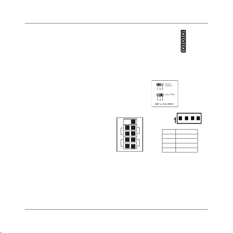
4-JBAT(CMOS Memory Clearing Header)
The time to clear the CMOS memory occurs when (a) the CMOS data becomes corrupted, (b)
you forgot the supervisor or user password preset in the BIOS menu, (c) you are unable to
boot-up the system because the CPU ratio/clock was incorrectly set in the BIOS menu, or (d)
whenever there is modication on the CPU or memory modules.
This header uses a jumper cap to clear the CMOS
memory and have it recongured to the default values
stored in BIOS.
• Pins 1 and 2 shorted (Default): Normal operation.
• Pins 2 and 3 shorted: Clear CMOS memory.
5/8-SPEAK/FPANEL(Speaker Headers & Front Panel Switches)
HD_LED (Red): Hard Driver LED connector
This connector connects to the case-mounted
HD LED cable, and the LED will light when the
hard drive(s) is/are being accessed.
RST (Blue): Reset Switch
This connector connects to the case-mounted
reset switch which allows you to reboot without
SPEAK:
Pin No. Denition
1 SPK +
2 NC
3 NC
4 SPK -
having to power-off the system and thus prolonging the life of the power supply or system.
PWR_ON (Black): Power Switch
Depending on the setting in the BIOS setup, this switch serves two functions which will allow
you to power-on/off the system or to enter the suspend mode.
PWR_LED (Green): Power/Standby LED
When the system's power is on, this LED will light. When the system is in the S1 (POS - Power
on Suspend) or S3 (STR - Suspend to RAM, optional) state, it will blink every second.
SPEAKER (Yellow or Black): Speaker Connector
This 4-pin connector connects to the case-mounted speaker.
- 14 -
Page 15

3
4
GN D
GN D
+12 V
+12 V
1 2
PW R 12V
1
13
10
20
+ .3 3V
+5 V
GND
PWR GD
PS ON-
N C/
+ .3 3V
GND
+1 2V
+5 V
GND
+5 VS B
+ .3 3V
-1 2V
GND
GND
GND
GND
+5 V
+5 V
ATX PWR
MINIX
7025-UC3 User's Manual
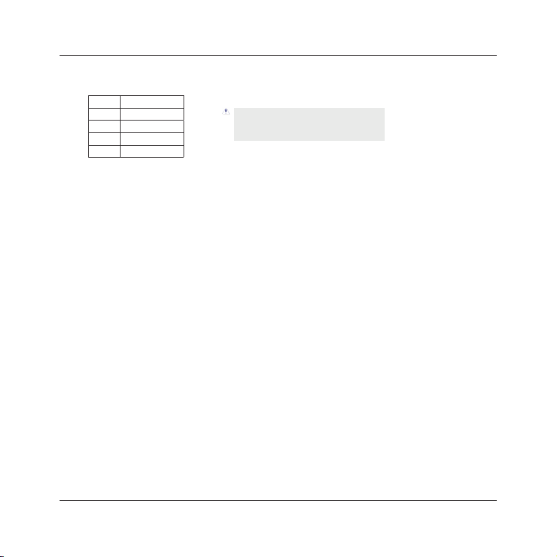
6/11- ATX Power Input Connectors
ATXPWR (ATX Power) connector
We recommend to use our motherboard with a power supply that complies with the ATX12V
Power Supply Design Guide Version 1.1. Every ATX12V power supply unit has a standard
24-pin ATX main power connector that must be plugged into this connector. If you would like
to use an old power supply with only a 20-pin ATX main power connector, then please plug
the 20-pin ATX main power connector along with pin 1 and pin 13.
PWR12V (+12V Power) connector
Your power supply unit may come with a 4-pin or 8-pin +12V power connector. The +12V
power enables the delivery of more +12VDC current to the CPU's Voltage Regulator Module
(VRM). Please connect the 4-pin power
to this connector.
7-FUSB1/FUSB2(Additional USB Port Headers)
Pin No. Denition Pin No. Denition
1 VCC 2 VCC
3 Data 0- 4 Data 15 Data 0+ 6 Data 1+
7 Ground 8 Ground
10 NC
- 15 -
Page 16
MINIX
7025-UC3 User's Manual
10-CFAN(CPU Fan Power Connectors Header)
FAN:CPU fan connectors
C
Pin No. Denition
1 GND
2 +12V
3 RPM
4 Control
These fan connectors are not jumpers.
DO NOT plac e jumpe r ca ps on these
connectors.
12-JLPC
This set of headers are reserved for internal debug purpose.
- 16 -
Page 17

MINIX
7025-UC3 User's Manual
Chapter 4 BIOS Setup Utility
BIOS stands for Basic Input and Output System. It was once called ROM BIOS when it was stored
in a Read-Only Memory (ROM) chip. Now manufacturers would like to store BIOS in EEPROM which
means Electrically Erasable Programmable Memory. BIOS used in this series of mainboard is stored
in EEPROM, and is the rst program to run when you turn on your computer.
BIOS performs the following functions:
1. Initializing and testing hardware in your computer (a process called "POST", for Power On Self
Test).
2. Loading and running your operating system.
3. Helping your operating system and application programs manage your PC hardware by means of
a set of routines called BIOS Run-Time Service.
4.1 About BIOS Setup
BIOS Setup is an interactive BIOS program that you need to run when:
1. Changing the hardware of your system. (For example: installing a new Hard Disk etc.)
2. Modifying the behavior of your computer. (For example: changing the system time or date, or
turning special features on or off etc.)
3. Enhancing your computer's behavior. (For example: speeding up performance by turning on
shadowing or cache)
4.2 To Run BIOS Setup
First access BIOS setup menu by pressing <F1> key after “POST” is complete (before OS is
loaded). After the rst BIOS be setupped(or loaded default values) and save, the <DEL> key will
be pressed if you will enter BIOS setup menu.
4.3 About CMOS
CMOS is the memory maintained by a battery. CMOS is used to store the BIOS settings you have
selected in BIOS Setup. CMOS also maintains the internal clock. Every time you turn on your
computer, the BIOS Looks into CMOS for the settings you have selected and congures your
computer accordingly. If the battery runs out of power, the CMOS data will be lost and POST will
issue a “CMOS invalid” or “CMOS checksum invalid” message. If this happens, you have to replace
the battery and check and congure the BIOS Setup for the new start.
4.4 The POST (Power On Self Test)
POST is an acronym for Power On Self Test. This program will test all things the BIOS does
- 17 -
Page 18
MINIX
7025-UC3 User's Manual
before the operating system is started. Each of POST routines is assigned a POST code, a unique
number which is sent to I/O port 080h before the routine is executed.
4.5 BIOS Setup — CMOS Setup Utility
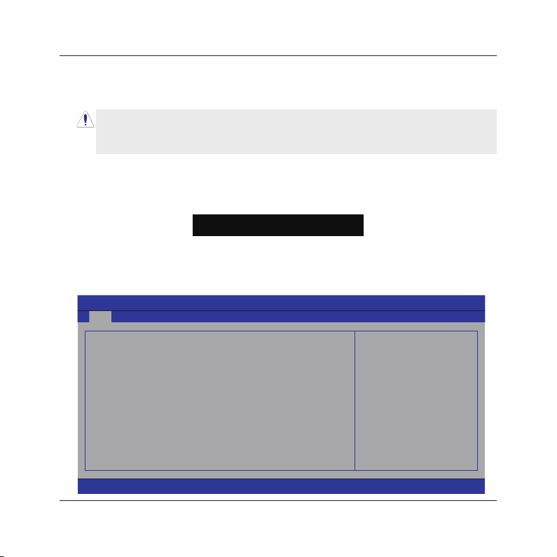
After powering up the system, the BIOS message appears on the screen,when the rst time or
when CMOS setting wrong, there is following message appears on the screen , but if the rst
rst BIOS be setuped(or loaded default values) and save, the <DEL> key will be pressed if you
will enter BIOS setup menu.
If this message disappears before you respond, restart the system by pressing <Ctrl> + <Alt>+
<Del> keys, or by pressing the reset button on computer chassis. Only when these two methods
should be fail that you restart the system by powering it off and then back on.
After pressing <F1> or <Del> key, the main menu appears.
improving the BIOS menu. The BIOS setup screens and descriptions illustrated in this manual
are for your reference only, and may not completely match with what you see on your screen.
Do not change the BIOS parameters unless you fully understand its function.
•
4.5.1 CMOS Setup Utility
Press F1 to Run SETUP
In order to increase system stability and performance, our engineering staff is constantly
•
BIOS SETUP UTILITY
Main Advanced Boot Security Power JUSTW00t! Exit
►
System Information
System Time
System Date
Power On Beep
►
SATA Port 1
►
SATA Port 2
►
SATA Port 3
►
SATA Port 4
►
CPU TDP Verify
[20:50:32]
[Tue 09/03/2009]
[Enabled]
: [ST380215AS]
: [Not Detected]
: [Not Detected]
: [Not Detected]
[Disabled]
Select Screen
←
↑↓
Select Item
Enter Go to Sub Screen
F1 General Help
F10 Save and Exit
ESC Exit
v02.61 (C)Copyright 1985-2006, American Megatrends, Inc.
- 18 -
Page 19

MINIX
7025-UC3 User's Manual
The menu bar on top of the screen has the following main items:
Main For changing the basic system conguration.
Advanced For changing the advanced system settings.
Boot For changing the system boot conguration.
Security For changing the system security setttings.
Power For changing the advanced power management(APM) conguration.
Exit For selecting the exit options and loading default settings.
4.5.2 Control Keys
Press F1 to pop up a small help window that describes the appropriate keys to use and the
possible selections for the highlighted item.
Please check the following table for the function description of each control key.
Control Key(s) Function Description
← / →
↑
/ ↓
+/
-
<Enter>
<ESC>
<F1>
<F2/F3>
<F7>
<F8>
<F9>
<F10>
Move cursor left or right to select Screens
Move cursor up or down to select items
To Change option for the selected items
To bring up the selected screen
Main Menu - Quit and not save changes into CMOS Status Page
Setup Menu and Option Page Setup Menu - Exit current page and
return to Main Menu
General help
Change Colors
Discard Changes
Load Failsafe Defaults
Load Optimal Defaults
Save conguration changes and exit setup
- 19 -
Page 20
MINIX
7025-UC3 User's Manual
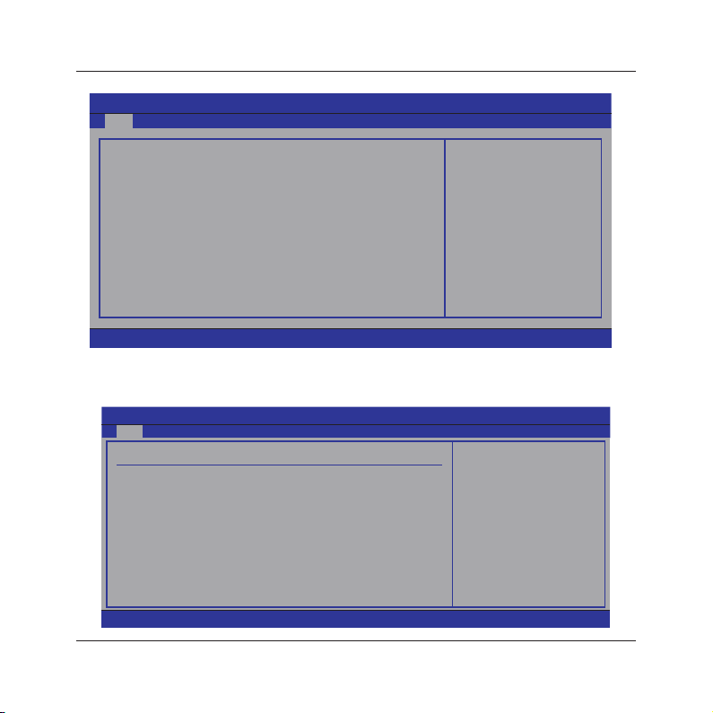
4.5.3 Main Menu
BIOS SETUP UTILITY
Main Advanced Boot Security Power JUSTW00t! Exit
►
System Information
System Time
System Date
Power On Beep
►
SATA Port 1
►
SATA Port 2
►
SATA Port 3
►
SATA Port 4
►
CPU TDP Verify
[20:50:32]
[Tue 09/03/2009]
[Enabled]
: [ST380215AS]
: [Not Detected]
: [Not Detected]
: [Not Detected]
[Disabled]
Select Screen
←
↑↓
Select Item
Enter Go to Sub Screen
F1 General Help
F10 Save and Exit
ESC Exit
v02.61 (C)Copyright 1985-2006, American Megatrends, Inc.
►
System Information
Please Enter this submenu, this will be display BIOS verison, build date, ID number, also will
display CPU type, Speed, count, and Memory Size and so on.
Main
System Overview
AMIBIOS
Version :08.00.15
Build Date:07/19/10
ID :C61130F0
Processor
AMD Athlon(tm)II X2 240 Processor
Speed :2800MHz
Count :2
System Memory
Size :2008MB
v02.61 (C)Copyright 1985-2006, American Megatrends, Inc.
BIOS SETUP UTILITY
- 20 -
Select Screen
←
↑↓
Select Item
F1 General Help
F10 Save and Exit
ESC Exit
Page 21

MINIX
7025-UC3 User's Manual
• System time
This item sets the time you specify(usually the current time)in the format of [Hour],[Minute]and
[Second].
• System date
This item sets the date you specify(usually the current date in the format of [Month],[Date],and
[Year].
• Power on Beep
A beep on post.Options: Disabled,Enabled.
►
SATA Port 1/2/3/4
This item sets the status of auto detection of SATA/IDE devices while enterting setup, and BIOS
will auto detects the presence of SATA/IDE devices. Press "Enter" Key to enter the submenu.
Main
SATA Port1 Disabled: Disables LBA
Device :Hard Disk
Vendor :ST380215AS
Size :80.0GB
LBA Mode :Supported
Block Mode:16Sectors
PIO Mode :4
Async DMA :MultiWord DMA-2
Ultra DMA :Ultra DMA-6
S.M.A.R.T.:Supported
LBA/Large Mode
Block (Multi-Sector Transfer)
PIO Mode
DMA Mode
S.M.A.R.T
32Bit Data Transfer
• LBA/Large Mode
Enables or disables the LBA mode. Setting to [Auto] enables the LBA mode if the device supports
this mode, and if the device was not previously formatted with LBA mode disabled.
• Block (Multi-Sector Transfer)
Enables or disables data multi-sectors transfers. When set to [Auto] , the data transfer from and
to the device occurs multiple sectors at a time if the device supports multi-sector transfer frature.
When set to [Disabled] , the data transfer from and to the device occurs one sector at a time.
v02.61 (C)Copyright 1985-2006, American Megatrends, Inc.
BIOS SETUP UTILITY
[Auto]
[Auto]
[Auto]
[Auto]
[Auto]
[Enabled]
Mode.
Auto: Enables LBA
Mode if the device
supports it and the
device is not already
formatted with LBA
Mode disabled.
Select Screen
←
↑↓
Select Item
+- Change Option
F1 General Help
F10 Save and Exit
ESC Exit
- 21 -
Page 22
MINIX
7025-UC3 User's Manual
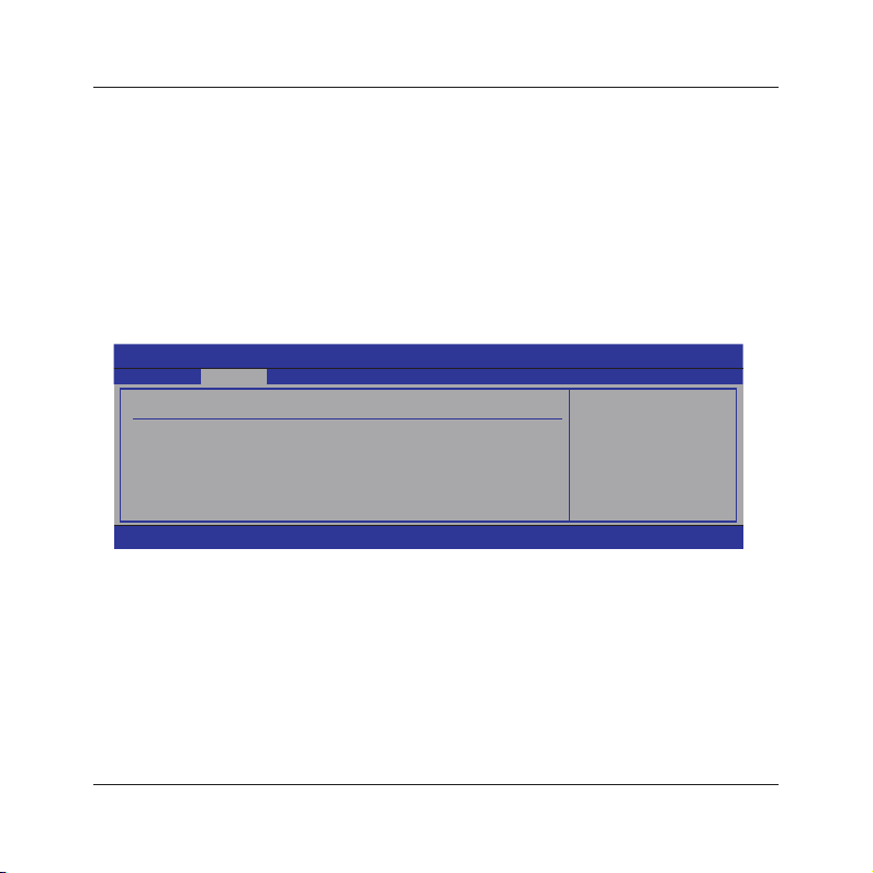
• PIO Mode
Allows you to select the data transfer mode.
• DMA Mode
Selects the DMA mode.
• S.M.A.R.T
Set the Smart Monitoring, Analysis, and Reporting Technology.
• 32Bit Data Transfer
Enables or disables 32-bit data transfer.
• Back to Main Setup Menu
• CPU TDP Verify
Options: Disabled,Enabled.
4.5.4 Advanced Setting
BIOS SETUP UTILITY
Main Advanced Boot Security Power JUSTW00t! Exit
Advanced Settings Configure CPU.
►
CPU Configuration
►
Chipset
►
Onboard Device
►
PCIPnP
Select Screen
←
↑↓
Select Item
Enter Go to Sub Screen
F1 General Help
F10 Save and Exit
ESC Exit
v02.61 (C)Copyright 1985-2006, American Megatrends, Inc.
This submenu including these congurations, such as CPU, Northbridge, Southbridge, Onboard
Device, only CPU Conguration submenu dispay diallog box as follwoing.
►
CPU Conguration
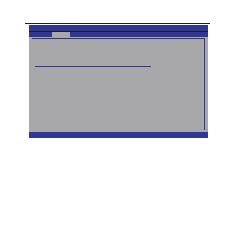
Click <Enter> key to enter its submenu, it will be display congureted CPU information,
including Module Version, Manufacturer , CPU type, Frequency, FSB Speed, Cache L1 , Cache
L2 and so on.
- 22 -
Page 23
MINIX
7025-UC3 User's Manual
Advanced
CPU Configuration
Moudule Version: 14.16
AGESA Version: 3.7.0.0
Physical Count : 1
Logical Count : 2
AMD Athlon(tm) II X2 240 Processor
Revision: C2
Cache L1: 384KB
Cache L2: 1536KB
Speed : 2727MHz, NB Clk: 1800MHz
Able to Change Freq. : Yes
uCode Patch Level : 0x1000083
GART Error Reporting
Microcode Update
Secure Virtual Machine Mode
Cool 'N 'Quiet
ACPI SRAT Table
v02.61 (C)Copyright 1985-2006, American Megatrends, Inc.
• GART Error Reporting
This option should remain disabled for the normal operation.The Driver developer may enable it
for testing purpose.
• Microcode Update.
Options:Disabled,Enabled.
• Secure Virtual Machine Mode
Enable/Disable Secure Virtual Machine Mode(SVM).
• Cool'n'Quiet
Enable/disable the generation of ACPI_PPC,_PSS,and_PCI objects.
• ACPI SRAT Table
Enable or Disable the building of ACPI SRAT Table.
• Turbo Core
Disable/Enable Turbo core funcion of 6 cores cpu. Options:Disabled,Enabled.
• Back to Advanced Setup Menu
BIOS SETUP UTILITY
[Disabled]
[Enabled]
[Enabled]
[Enabled]
[Enabled]
- 23 -
This option should
remain disabled for
the normal operation.
The driver developer
may enable it for
testing purpose.
Select Screen
←
↑↓
Select Item
+- Change Option
F1 General Help
F10 Save and Exit
ESC Exit
Page 24
MINIX
7025-UC3 User's Manual
►
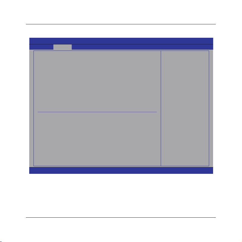
Chipset Conguration
Click <Enter> key to enter its submenu, it will be display chipset conguration.
Advanced
Advanced Chipset Setting Options
WARNING: Setting wrong values in below sections
may cause system to malfunction.
NUMM ROM Version: 4.082.10
Primary Graphics Adapter [PCI Express->PCI]
OnChip and PCIe VGA selection [Disable Onchip]
iGPU Frame Buffer Detect [Auto]
OnChip VGA Frame Buffer Size [32MB]
IDE Configuration
Serial-ATA 0
Hard Disk Write Protect
IDE Detect Time Out(Sec)
ATA(PI) 80Pin Cable Detection
RAID Setup
nVidia RAID Function
v02.61 (C)Copyright 1985-2006, American Megatrends, Inc.
• Primary Graphics Adapter
Options:PCI Express ->PCI->IGP,IGP->PCI->PCI Express
• OnChip and PCIe VGA selection
Select OnChip or PCIe VGA to diaplay
• iGPU Frame Buffer Detect
iGPU Frame Buffer Size Auto Detect
BIOS SETUP UTILITY
[Enable]
[Disable]
[35]
[Host]
[Disabled]
PCI Express->PCI->
I G P - > P C I - > P C I
Express
Select Screen
←
↑↓
Select Item
Enter Go to Sub
Screen
F1 General Help
F10 Save and Exit
ESC Exit
- 24 -
Page 25
MINIX 7025-UC3 User's Manual
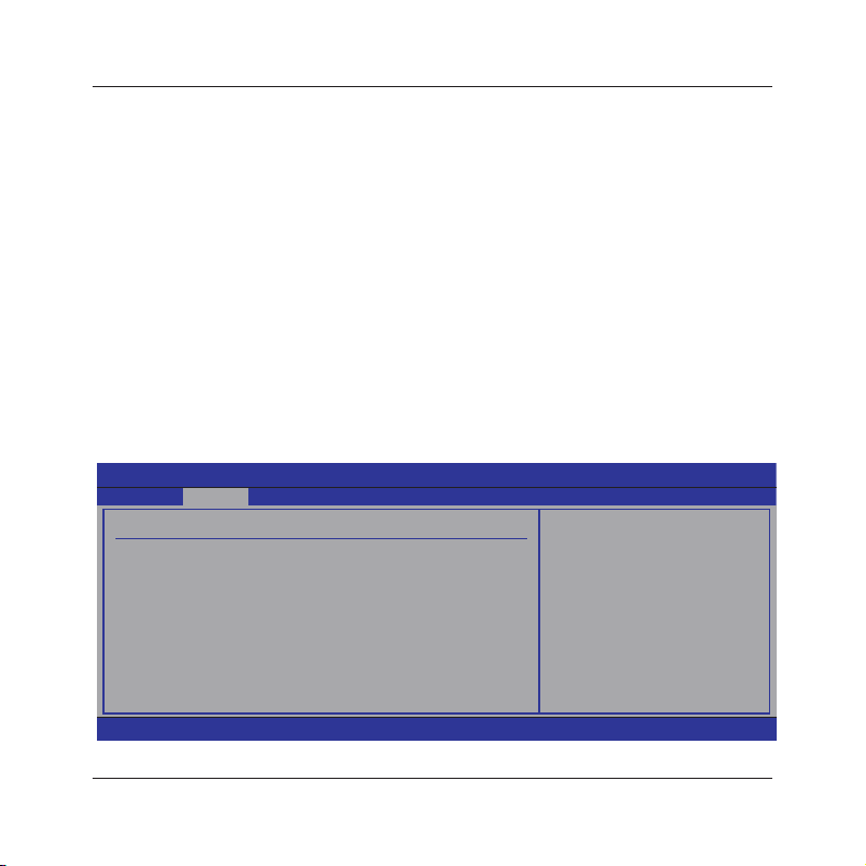
• OnChip VGA Frame Buffer Size
iGPU Frame Buffer size.
• Onboard IDE Controller
Allows BIOS to Enable or Disable IDE Controller
• Serial-ATA 0
Options:Enabled,Disabled.
• Hard disk write protect
Disable/enable device write protection.this will be efctive only if device is accessed through
BIOS.
• IDE Detect Time Out
Select the time out value for detecting ATA/ATAPI device(s)
• ATA(PI) 80Pin Cable Detection
Select the mechanism for detecting 88pin ATA(PI) Cable.
• nVidia RAID Function
Options:Enabled,Disabled.
• Back to Advanced Setup Menu
►
Onboard Device
Click <Enter> key to enter its submenu.
BIOS SETUP UTILITY
Advanced
Onboard Devices Setting Configure the USB support.
►
USB Device
AZALIAIDE AUDIO
Lan Controller
Saming/BootROM control
Serial Port1 Address
[Disabled]
[35]
[Host & Device]
[3F8/IRQ4]
Select Screen
←
↑↓
Select Item
+- Change Option
F1 General Help
F10 Save and Exit
ESC Exit
v02.61 (C)Copyright 1985-2006, American Megatrends, Inc.
- 25 -
Page 26
MINIX 7025-UC3 User's Manual
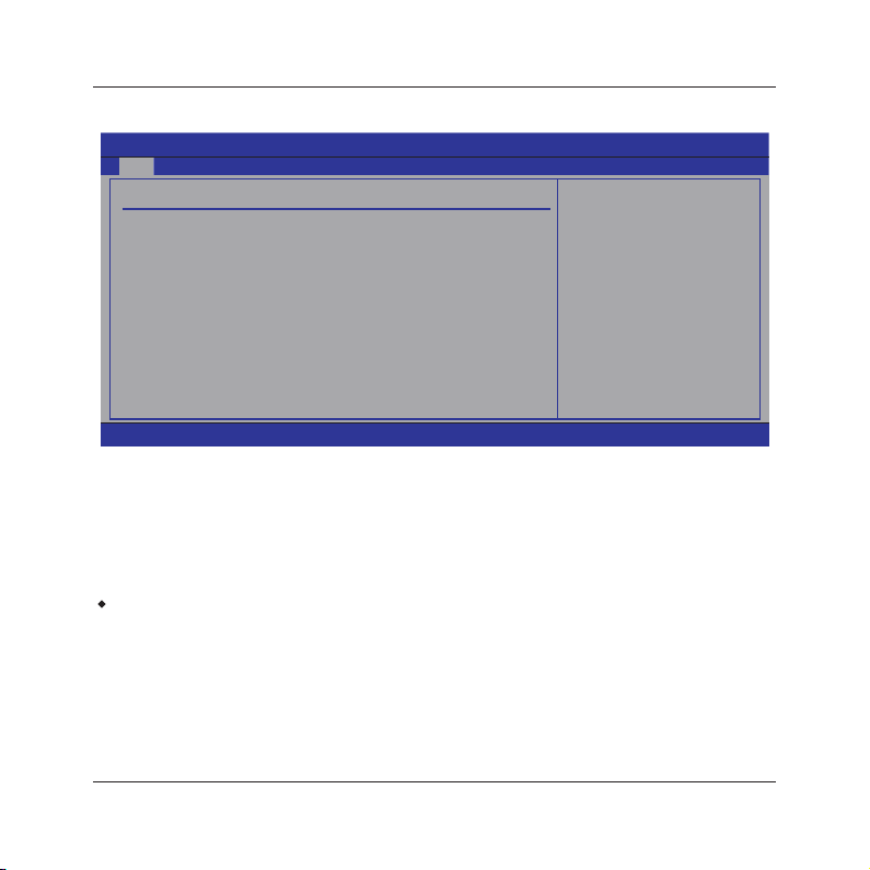
►
USB Device
The items in this menu allows you to change the USB-related features.
Main
USB Configuration Enables support for
Module Version -2.24.3-13.4
USB Devices Enabled :
None
Legacy USB Support
USB 2.0 Controller Mode
BIOS EHCI Hand-Off
USB1 1.1 Controller
USB1 2.0 Controller
• Legacy USB Support
Enabled or Disabled Legacy USB option, and Auto option disables legacy support if no USB
devices are connected.
• USB 2.0 Controller Mode
Allow you to selects the HiSpeed(480Mbps) or FullSpeed(12Mbps).
• BIOS EHCI Hand-Off
This is a workaround for OSes without EHCI hand-off support. The EHCI ownership change
should claim by EHCI driver.
Press <Esc> key to return to "Onboard Device Conguration" menu.
・
• AZALIA AUDIO
Options:Auto,Disabled
• Lan Controller
Options:Auto,Disabled
• Saming/BootRom Control
MAC LAN rom boot Set
• Serial Port1 Address
Allows BIOS to Select Serial Port1 base Addresses.
v02.61 (C)Copyright 1985-2006, American Megatrends, Inc.
BIOS SETUP UTILITY
[Enabled]
[HiSpeed]
[Enabled]
[Enabled]
[Enabled]
- 26 -
legacy USB. AUTO
option disables
legacy support if
no USB devices are
connected.
Select Screen
←
↑↓
Select Item
+- Change Option
F1 General Help
F10 Save and Exit
ESC Exit
Page 27
MINIX
7025-UC3 User's Manual
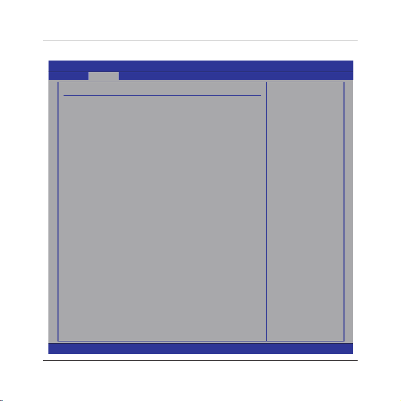
►
PCIPnP
Click <Enter> key to enter its submenu.
Advanced
Advanced PCI/PnP Settings Clear NVRAM during
WARNING: Setting wrong values in below sections
may cause system to malfunction.
BIOS SETUP UTILITY
System Boot.
Clear NVRAM
Plug & Play O/S
PCI Latency Timer
Allocate IRQ to PCI VGA
Palette Snooping
PCI IDE BusMaster
OffBoard PCI/ISA IDE Card
IRQ3
IRQ4
IRQ5
IRQ7
IRQ9
IRQ10
IRQ11
IRQ14
IRQ15
DMA Channel 0
DMA Channel 1
DMA Channel 3
DMA Channel 5
DMA Channel 6
DMA Channel 7
Reserved Memory Size
v02.61 (C)Copyright 1985-2006, American Megatrends, Inc.
[No]
[No]
[64]
[Yes]
[Disabled]
[Enabled]
[Auto]
[Available]
[Available]
[Available]
[Available]
[Available]
[Available]
[Available]
[Available]
[Available]
[Available]
[Available]
[Available]
[Available]
[Available]
[Available]
[Disabled]
- 27 -
Select Screen
←
↑↓
Select Item
+- Change Option
F1 General Help
F10 Save and Exit
ESC Exit
Page 28

MINIX 7025-UC3 User's Manual
• Clear NVRAM
This item for clearing NVRAM during system boot.
Optional:Yes,No
• Plug & Play O/S
This item lets the BIOS congure all the devices in the system or lets the operating system
congure plug and play (PnP) devices not required for boot if your system has a Plug and Play
operating system.
Optional:Yes,No
• PCI Latency Timer
This item sets value in units of PCI clocks for PCI device latency timer register.
Optional:32,64,96,128,160,192,224,248
• Allocate IRQ to PCI VGA
This item assigns IRQ to PCI VGA card if card requests IRQ or doesn't assign IRQ to PCI VGA
card even if card requests an IRQ.
Optional:Yes,No
• Palette Snooping
This item informs the PCI devices that an ISA graphics device is installed in the system so the
card will function correctly.
Optional:Disabled,Enabled
• PCI IDE BusMaster
This item uses PCI busmastering for BIOS reading / writing to IDE derives.
Optional:Disabled,Enabled
• OffBoard PCI/ISA IDE Card
This item works for most PCI IDE cards, some PCI IDE cards may require this to be set to the
PCI slot number that is holding the card.
Optional:Auto,PCI Slot1~6
• Reserved Memory Size
Size of memory block to reserve for legacy ISA devices.
• Engineer mode
Engineer mode control.
- 28 -
Page 29
MINIX 7025-UC3 User's Manual
4.5.5 Boot Setting
Main Advanced Boot Security Power PC&Health Exit
Boot Settings Configure Settings
►
Boot Settings Configuration
►
Boot Device Priority
►
Hard Disk Drives
►
Removable Drives
►
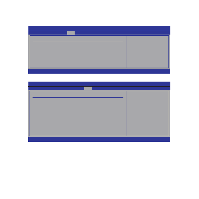
Boot Settings Conguration
Click <Enter> key to enter its submenu.
Boot Settings Configuration Allows BIOS to skip
Quick Boot
Full Screen Logo
Bootup Num-Lock
Halt On
Wait For 'F1' If Error
Hit 'Del' Message Display
Interrupt 19 Capture
• Quick Boot
This item allows you to speed up Power On Self Test (POST) after you power on the computer. If
this is set to [Enabled], BIOS will shorten or skip some check items during POST.
• Full screen Logo
This allows you to enable or disable the full screen logo display feature.
• Bootup Num-Lock
Allows you to select the power-on state for the NumLock.
v02.61 (C)Copyright 1985-2006, American Megatrends, Inc.
v02.61 (C)Copyright 1985-2006, American Megatrends, Inc.
BIOS SETUP UTILITY
BIOS SETUP UTILITY
Boot
[Enabled]
[Disabled]
[On]
[No Errors]
[Enabled]
[Enabled]
[Enabled]
during System Boot.
Select Screen
←
↑↓
Select Item
Enter Go to Sub Screen
F1 General Help
F10 Save and Exit
ESC Exit
certain tests while
booting. This will
decrease the time
needed to boot the
system.
←
↑↓
+- Change Option
F1 General Help
F10 Save and Exit
ESC Exit
Select Screen
Select Item
- 29 -
Page 30

MINIX 7025-UC3 User's Manual
• Halt On
Options:All Errors,No Errors,All But Keyboard.
• Wait For 'F1' If Error
When set to Enabled,the system waits for the F1 key t be pressed when error occurs.
• Hit 'Del' Message Display
When set to Enabled,the system displays the message "Press DEL to run Setup" durning POST.
• Interrupt 19 Capture
When set to Enabled, this function allows the option ROMs to trap Interrupt 19.
• Back to Boot Setup Menu
►
Boot Device Priority
Click <Enter> key to enter submenu, it will be display species the boot sequence from the
available devices.
►
Hard Disk Drives
Click <Enter> key to enter submenu, it will be display species the boot device priority sequence
from available hard disk drives.
►
Removable Drives
Click <Enter> key to enter submenu, it will be display species the boot device priority sequence
from available removable drives.
- 30 -
Page 31
MINIX
7025-UC3 User's Manual
4.5.6 Security Setting
Main Advanced Boot Security Power PC&Health Exit
Security Settings Install or Change the
Supervisor Password : Not Installed
User Password : Not Installed
Change Supervisor Password
User Access Level
Change User Password
Clear User Password
Password Check
Boot Sector Virus Protection
Flash Write Protection
v02.61 (C)Copyright 1985-2006, American Megatrends, Inc.
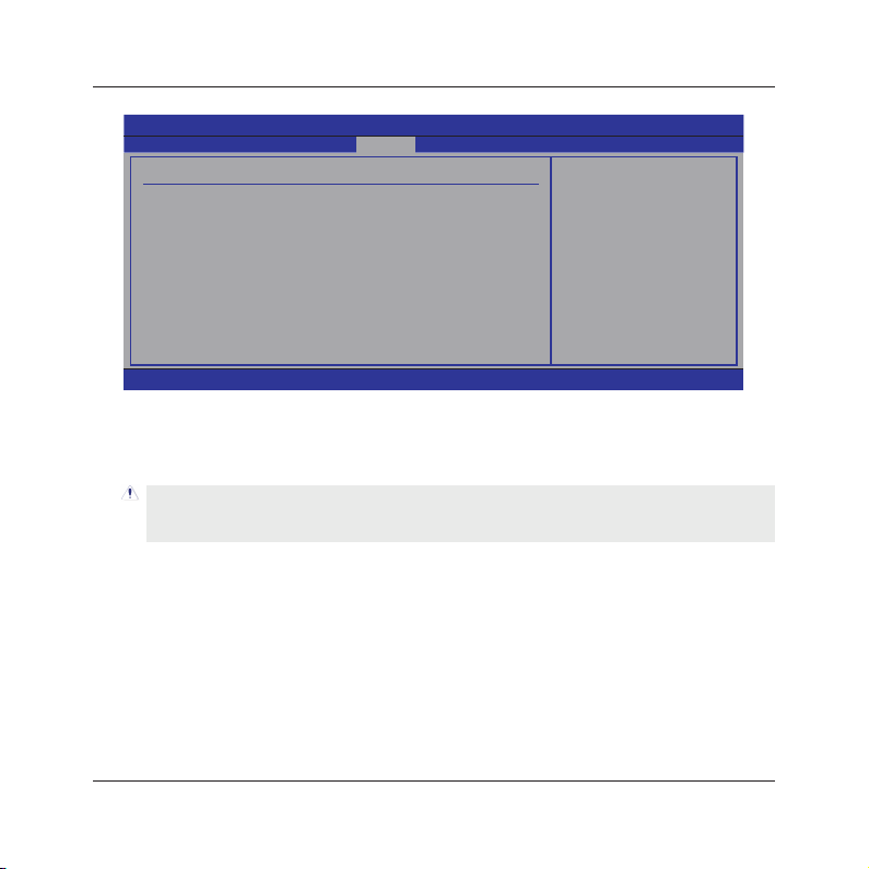
This item allows you to Chage Supervisor/User Password, Type the password, up to eight
characters, and press <Enter>. The password typed now will clear any previously entered
password from CMOS memory. You will be asked toconrm the password. Type the password
again and press <Enter>.
Note: Don’t forget your password. If you forget the password, you will have to open the
computer case and clear all information in the CMOS before you can start up the system.
But by doing this, you will have to reset all previously set options.
• Boot Sector Virus Protection
Enabled/Disable Boot Sector Virus Protection
• Flash Write Protection
Options:Enabled,Disabled.
BIOS SETUP UTILITY
[Full Access]
[Setup]
[Disabled]
[Enabled]
password.
Select Screen
←
↑↓
Select Item
Enter Change
F1 General Help
F10 Save and Exit
ESC Exit
- 31 -
Page 32
MINIX 7025-UC3 User's Manual
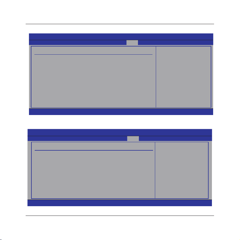
4.5.7 Power Setting
Main Advanced Boot Security Power JUSTw00T! Exit
Power Settings Section for Advanced
►
ACPI Configuration
►
APM Configuration
►
PC Health
v02.61 (C)Copyright 1985-2006, American Megatrends, Inc.
►
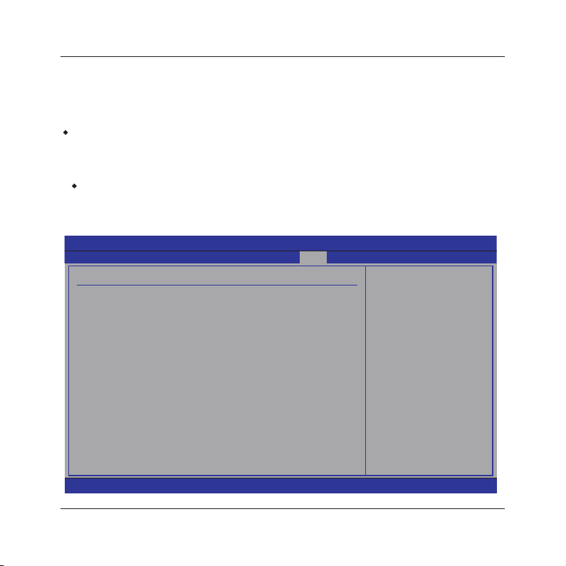
ACPI Conguration
Click <Enter> key to enter its submenu.
ACPI Configuration Select the ACPI
ACPI Aware O/S
Suspend mode
ACPI Version Festures
ACPI APCI support
v02.61 (C)Copyright 1985-2006, American Megatrends, Inc.
BIOS SETUP UTILITY
BIOS SETUP UTILITY
Power
[Yes]
[S1 (POS)]
[ACPI V1.0]
[Enabled]
ACPI Configuration.
Select Screen
←
↑↓
Select Item
Enter Go to Sub Screen
F1 General Help
F10 Save and Exit
ESC Exit
state used for
System Suspend.
←
↑↓
+- Change Option
F1 General Help
F10 Save and Exit
ESC Exit
Select Screen
Select Item
- 32 -
Page 33
MINIX 7025-UC3 User's Manual
• ACPI Aware O/S
Enable/Disable ACPI support for Operating system
• Suspend Mode
Allows you to select the Advanced Conguration and Power Interface (ACPI) state to be used
for system suspend.
ACPI Version Features
・
Enable RSDP pointers to 64-bit Fixed system Description tables
• ACPI APCI support
Include ACPI APCI table Pointer to RADT pointer list.
・Press <Esc> key to return to "Power" menu.
►
APM Conguration
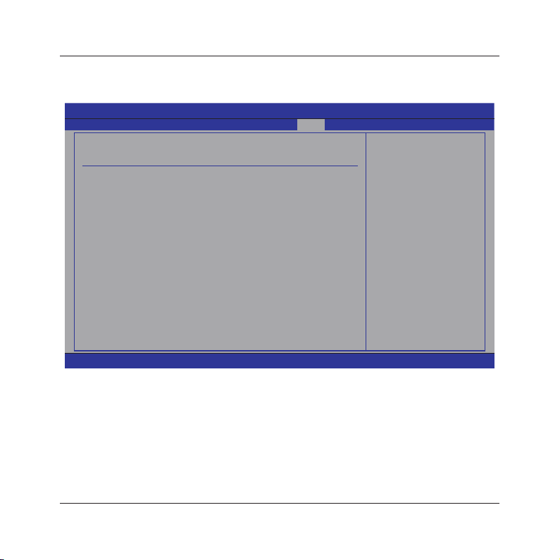
Click <Enter> key to enter its submenu, APM Conguration Template Manager allows
you to manage Power Managerment default or custom conguration templates.
BIOS SETUP UTILITY
APM Configuration EuP Function,Super IO
EuP Function
Power Button Mode
APM Resume Event Confoguration
Resume On PME#
Resume On PCIE Wake#
Resume On USB
Resume By RTC Alarm
Resume By PS2 Mouse
Resume By PS2 Keyboard
Restore on AC Power Loss
[Disabled]
[On/Off]
[Disabled]
[Disabled]
[Disabled]
[Disabled]
[Disabled]
[Disabled]
[Power Off]
Power
power SAVING function.
Disabled
Enabled
Select Screen
←
↑↓
Select Item
+- Change Option
F1 General Help
F10 Save and Exit
ESC Exit
v02.61 (C)Copyright 1985-2006, American Megatrends, Inc.
- 33 -
Page 34
MINIX
7025-UC3 User's Manual
►
PC Health
Click <Enter> key to enter its submenu, it will be display hardware health conguration,
including System temperature, CPU temperature, FAN speed and all kinds of voltages.
BIOS SETUP UTILITY
PC Health
H/W Health Function [Enabled]
System Temperature
CPU Temperature
CPUFAN Speed
SYSFAN1 Speed
CPU Voltage
CPU HT Voltage
Dram Voltage
+5V Voltage
+12V Voltage
VCC
VBAT
CPUFAN Mode Setting
Manual Duty Cycle Setting
v02.61 (C)Copyright 1985-2006, American Megatrends, Inc.
• CPUFAN Mode Setting
Available options: Manual Mode,Thermal Cruise Mode,Speed Cruise Mode
• Manual Duty Cycle Setting
Set Fan at xed Duty-Cycle Min=0 Max=100 Please input Dec number;
:23oC/73oF
:29oC/84oF
:1.384 V
:1.193 V
:1.542 V
:4.992 V
:12.104 V
:3.248 V
:2.960 V
[Manual Mode ]
[100]
Power
Fan configuration
mode setting
Select Screen
←
↑↓
Select Item
+- Change Option
F1 General Help
F10 Save and Exit
ESC Exit
- 34 -
Page 35
MINIX 7025-UC3 User's Manual
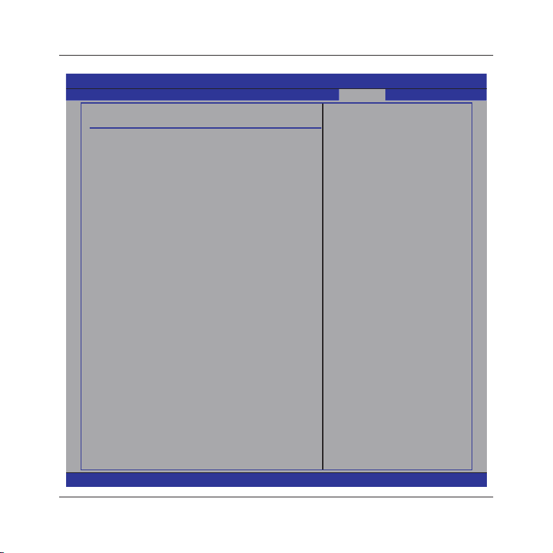
4.5.8 JUSTw00t! Setting(OverClock Settings)
Main Advanced Boot Security Power JUSTw00T! Exit
OverClock Settings
►
AMD Overclocking Configuration
►
DRAM Timing ConFiguration
►
Memory Configuration
Memory 2T Mode [2T Mode]
Memory CLK :N/A,667MHZ
CAS Latency(Tcl) :N/A,9 CLK
RAS/CAS Delay(Trcd) :N/A,9 CLK
Row Precharge Time(Trp) :N/A,9 CLK
Min Active RAS(Tras) :N/A,24 CLK
RAS/RAS Delay(trrd) :N/A,4 CLK
Row Cycle (Trc) :N/A,33 CLK
Write Recover Time(Twr) :N/A,6 CLK
CPU/LTD Spread Spectrum [200.0]
PCIE Spread Spectrum [Enabled]
SATA Spread Spectrum [Enabled]
GPU Over control [Auto]
CPU Frequency,MHZ [200.0]
MCP PCI-Express Frequency,MHZ [100]
CPU Voltage Control [Auto]
CPU Voltage :1.264v
K10 CPUNB Voltage Control [Auto]
DRAM Voltage Control [Auto]
DRAM Voltage :1.936 v
Chipset Voltage Control [Auto]
Chip Voltage :1.272v
BIOS SETUP UTILITY
ConFigur CPU
frequency and
voltage
Select Screen
←
↑↓
Select Item
Enter Go to Sub Screen
F1 General Help
F10 Save and Exit
ESC Exit
v02.61 (C)Copyright 1985-2006, American Megatrends, Inc.
- 35 -
Page 36
MINIX 7025-UC3 User's Manual
►
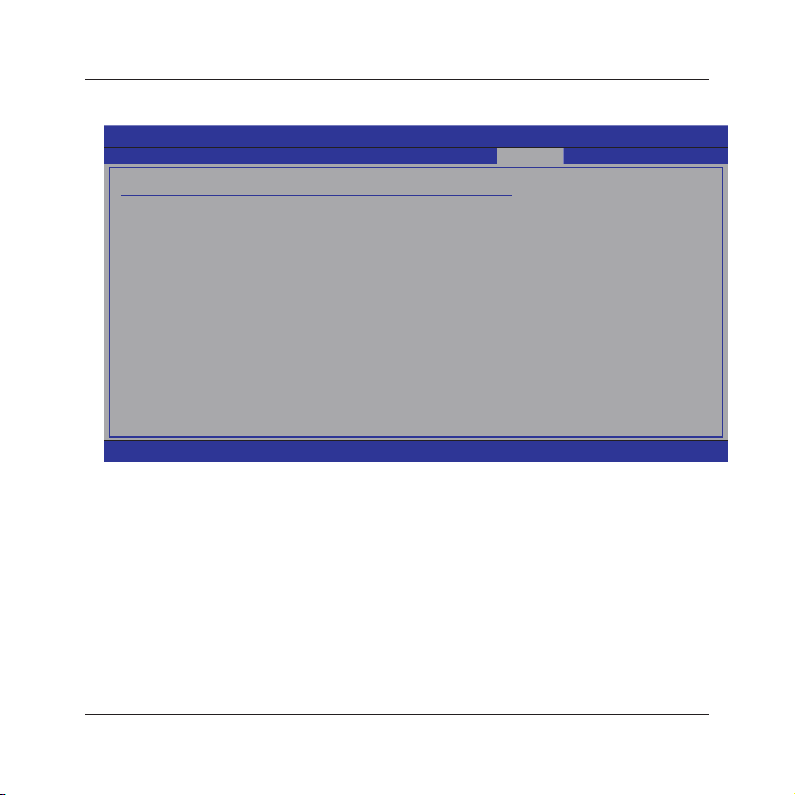
AMD Overclocking Conguration
Click <Enter> key to enter its submenu.
BIOS SETUP UTILITY
AMD Overclocking Configuration
Speed:2727MHZ, NB Clk:2000MHZ
Maximum FSB Multiplier :13.5x
Processor Frequency Multiplier [Auto]
Processor Voltage [Auto]
Processor NB Frequency(NBFID) [Auto]
Processor NB Voltage(NBVID) [Auto]
SB to K8(CPU) Freq Auto [Enabled]
SB to K8(CPU) LinkWidth [16
↓ 16↑
]
JUSTw00T!
Configure CPU
frequency and
voltage
Select Screen
←
↑↓
Select Item
Enter Go to Sub Screen
F1 General Help
F10 Save and Exit
ESC Exit
• Processor Frequency Multiplier
options:Auto,X4.0 800 MHZ,X4.5 900MHZ,X5.0 1000MHZ,X5.5 1100MHZ,X6.0 1200MHZ,X6.5
1300MHZ, X7.0 1400MHZ ,X7.5 1500MHZ
• Processor Voltage
Options:Auto,1.425V,1.412V,1.400V,1.387V,1.375V,1.362V,1.350V,1.337V
• Processor NB Frequency (NBFID)
Options:Auto,X4 800MHZ,X5 1000MHZ,X6 1200MHZ,X7 1400MHZ,X8 1600MHZ,X9 1800MHZ,
X10 2000MHZ,X11 2200MHZ.
• Processor NB Voltage(NBVID)
Options:Auto,1.425V,1.412V,1.400V,1.387V,1.375V,1.362V,1.350V,1.337V
• SB to K8(CPU) Freq Auto
SB to K8(CPU) frequency selection by CPU capability.
• SB to K8(CPU)LinkWidth
SB to K8(CPU) LinkWidth selection
v02.61 (C)Copyright 1985-2006, American Megatrends, Inc.
- 36 -
Page 37
MINIX 7025-UC3 User's Manual
Press <Esc> key to return to "JUSTw00T!" menu.
・
►
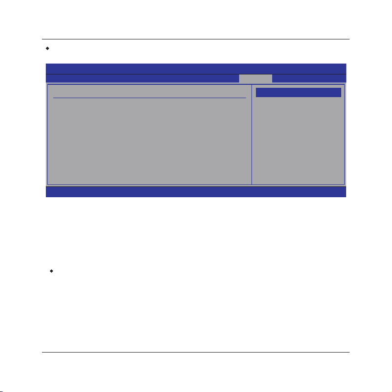
DRAM Timing Conguration
BIOS SETUP UTILITY
DRAM Timing Configuration
Memory Clock Mode
DRAM Timing Mode
Memory 2T Mode
v02.61 (C)Copyright 1985-2006, American Megatrends, Inc.
• Memory Clock Mode
This item is to select the memory clock mode.
• DRAM Timing Mode
This item is to select the DRAM Timing mode.
• Memory 2T Mode
Options:Auto, 1T Mode,2T Mode.
・Press <Esc> key to return to "JUSTw00T!" menu.
[Auto]
[Auto]
[2T Mode]
JUSTw00T!
Options
Auto
Limit
Manual
Select Screen
←
↑↓
Select Item
+- Change Option
F1 General Help
F10 Save and Exit
ESC Exit
- 37 -
Page 38
MINIX
7025-UC3 User's Manual
►
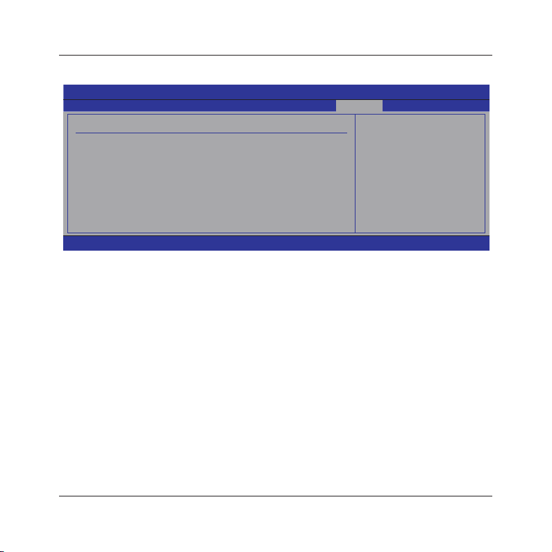
Memory Conguration
Click <Enter> key to enter its submenu.
BIOS SETUP UTILITY
JUSTw00T!
Memory Configuration Enable Bank Memory
Bank Interleavin
Channel Inter leaving
Enable Clock to All DIMMs
MemClk Tristate C3/ATLVID
Memory Hole Remapping
DCT Unganged Mode
Power Down Enable
Page Smashing
[Auto]
[Auto]
[Disabled]
[Disabled]
[Enabled]
[Always]
[Enabled]
[Disabled]
Interleaving
Select Screen
←
↑↓
Select Item
+- Change Option
F1 General Help
F10 Save and Exit
ESC Exit
v02.61 (C)Copyright 1985-2006, American Megatrends, Inc.
• Bank Interleaving
Sets the bank interleaving feature.
• Channel Interleaving
Enable Channel Memory Interleaving.
• Enable Clock to All DIMMs
This item is to enable or disable the unused clocks to DIMMs even the memory slots are not
populated.
• MemClk Tristate C3/ATLVID
Enables or disables the MemClk Tri-Stating during C3 and Alt VID.
• Memory Hole Remapping
Enables or disables the memory remapping around the memory hole.
• DCT Unganged Mode
This item allows the selection of the unganged DRAM mode (64-bit width).
• Power Down Enable
This item is to enable or disable the DDR power down mode.
• Page Smashing
S/W Control of Page Smashing Mechanism.
- 38 -
Page 39
MINIX 7025-UC3 User's Manual
4.5.9 Exit Setting
Main Advanced Boot Security Power JUSTw00t! Exit
Exit Options Exit system setup
Save Changes and Exit
Discard Changes and Exit
Discard Changes
Load Optimal Defaults
Load Failsafe Defaults
v02.61 (C)Copyright 1985-2006, American Megatrends, Inc.
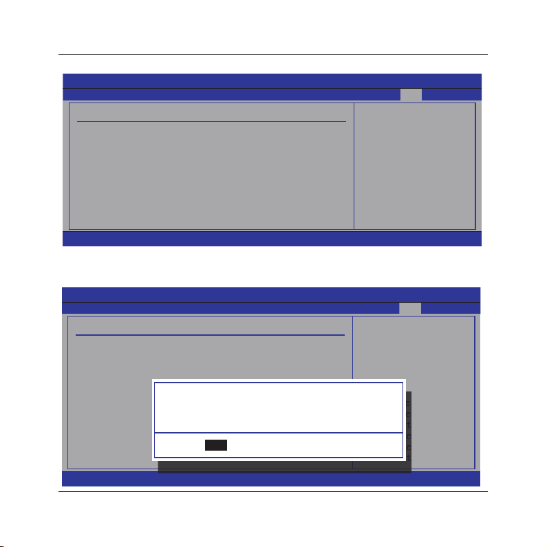
Highlight this item and select <Ok>,then press <Enter> to save the changes that you have
made in the Setup Utility and exit the Setup Utility. Or press <Cancel> to return to the main
menu.
Main Advanced Boot Security Power JUSTw00t! Exit
Exit Options Exit system setup
Save Changes and Exit
Discard Changes and Exit
Discard Changes
Load Optimal Defaults
Load Failsafe Defaults
Save configuration changes and exit setup?
v02.61 (C)Copyright 1985-2006, American Megatrends, Inc.
BIOS SETUP UTILITY
BIOS SETUP UTILITY
[Ok]
[Ok] [Cancel]
- 39 -
after saving the
changes.
Select Screen
←
↑↓
Select Item
Enter Go to Sub Screen
F1 General Help
F10 Save and Exit
ESC Exit
after saving the
changes.
F10 key can be used
for this operation.
←
↑↓
Enter Go to Sub Screen
F1 General Help
F10 Save and Exit
ESC Exit
Select Screen
Select Item
Page 40
MINIX 7025-UC3 User's Manual
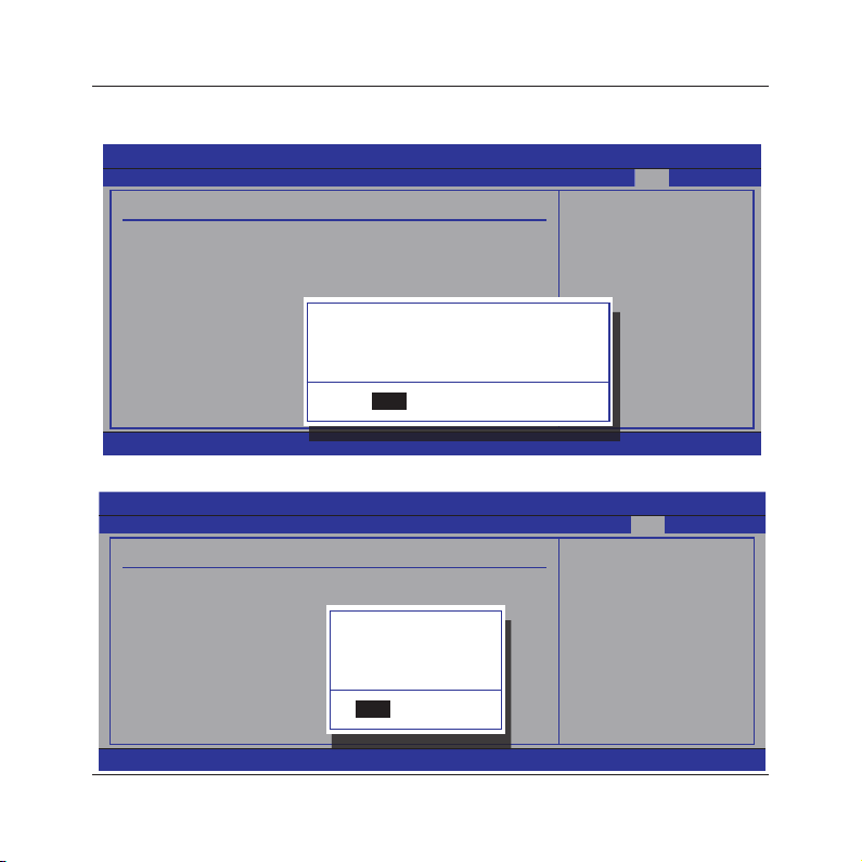
Highlight this item and select <Ok>,then press <Enter> to discard any changes that you have
made in the Setup Utility and exit the Setup Utility. Or press <Cancel> to return to the main
menu.
Main Advanced Boot Security Power JUSTw00t! Exit
Exit Options Exit system setup
Save Changes and Exit
Discard Changes and Exit
Discard Changes
Load Optimal Defaults
Load Failsafe Defaults
v02.61 (C)Copyright 1985-2006, American Megatrends, Inc.
Sleect <Ok>and press <Enter> to discard changes and exit, or press <Cancel> to return to the
main menu.
Main Advanced Boot Security Power JUSTw00t! Exit
Exit Options Discards changes
Save Changes and Exit
Discard Changes and Exit
Discard Changes
Load Optimal Defaults
Load Failsafe Defaults
v02.61 (C)Copyright 1985-2006, American Megatrends, Inc.
BIOS SETUP UTILITY
without saving any
changes.
ESC key can be used
for this operation.
Discard changes and exit setup?
[Ok]
[Ok] [Cancel]
BIOS SETUP UTILITY
Discard changes?
[Ok]
[Ok] [Cancel]
- 40 -
←
↑↓
Enter Go to Sub Screen
F1 General Help
F10 Save and Exit
ESC Exit
done so far to any of
the setup questions.
←
↑↓
Enter Go to Sub Screen
F1 General Help
F10 Save and Exit
ESC Exit
Select Screen
Select Item
Select Screen
Select Item
Page 41

MINIX
7025-UC3 User's Manual
This option opens a dialog box that let you install optimized defaults for all appropriate items in
the Setup Utility. Select <OK> and then <Enter> to install the defaults. select <Cancel> and
then <Enter> to not install the defaults. The optimized defaults place demand on the system
that may be greater than the performance level of the components, such as the CPU and the
memory. You can cause fatal errors or instability if you install the optimized defaults when your
hardware does not support them. If you only want to install setup defaults for a specic option,
select and display that option, and then press <F9>.
BIOS SETUP UTILITY
Main Advanced Boot Security Power JUSTw00t! Exit
Exit Options Load Optimal Default
Save Changes and Exit
Discard Changes and Exit
Discard Changes
Load Optimal Defaults
Load Failsafe Defaults
This option opens a dialog box that lets you install fail-safe defaults for all appropriate items in
the Setup Utility: Select <Ok> and the <Enter> to install the defaults. Select <Canel> and then
<Enter> to not install the defaults. The fail-safe defaults place no great demand on the system
and are generally stable. If your system is not functioning correctly, try installing the fail-safe
defaults as a rst step in getting your system working properly again.If you only want to install
fail-safe defaults for a specic option, select and display that option, and then press <F8>.
Load Optimal Defaults?
[Ok]
[Ok] [Cancel]
values for all the
setup questions.
F9 key can be used
for this operation.
BIOS SETUP UTILITY
Main Advanced Boot Security Power JUSTw00t! Exit
Exit Options Load Failsafe Default
Save Changes and Exit
Discard Changes and Exit
Discard Changes
Load Optimal Defaults
Load Failsafe Defaults
Load Failsafe Defaults?
[Ok]
[Ok] [Cancel]
values for all the
setup questions.
F8 key can be used
for this operation.
v02.61 (C)Copyright 1985-2006, American Megatrends, Inc.
- 41 -
Page 42
MINIX 7025-UC3 User's Manual
Chapter 5 Driver Installation
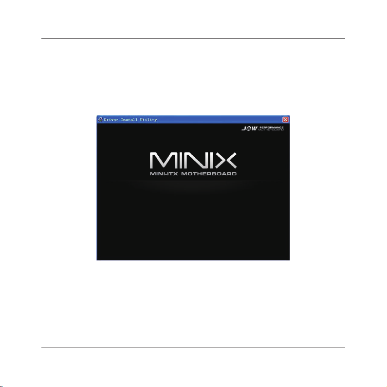
Check your package and there is Driver CD included. This CD consists of all drivers you need. In
addition, this CD also include an auto detect software which can tell you which hardware is installed,
and which drivers needed so that your system can function properly.
Insert CD into your CD-ROM drive and the menu should appear as below. If the menu does not
appear, double-click My Computer / double-click CD-ROM drive or click Start / click Run / type X:\
Setup.EXE (assuming X is your CD-ROM drive).
+ Mainboard Driver Installation Utility
+ Userful Software Utility
> Browse CD
Exit
(This picture is only for reference)
From the Main MENU you may make 4 selections:
1. +Mainboard Driver Installation Utility: Click to enter the driver installation menu.
2. +Useful Software Utility: Click to enter the utilities installation menu.
3. >Browse CD: Click to browse the contents of this “Driver & Utility CD”.
4. Exit: Click to exit this installation menu.
- 42 -
Page 43
MINIX 7025-UC3 User's Manual
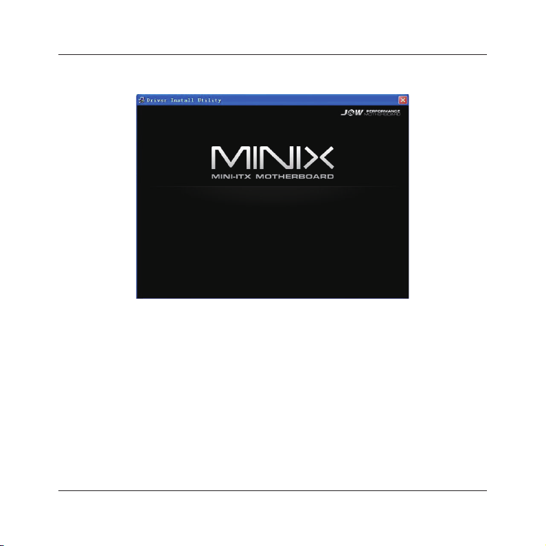
When you choose Mainboard Driver installation Utility, the drivers menu should appear as
below:
Back <- nForce Chipset Installation Utility
Nvidia VGA Graphics Driver
Onboard LAN Driver
Realtek HD Audio Driver
Exit
(This picture is only for reference)
From the Drivers MENU you may make 4 selections:
1. nForce Chipset Installation Utility
2. Nvidia VGA Graphics Driver
3. Onboard LAN Driver
4. Realtek HD Audio Driver
5. Exit: Click to exit this installation menu.
- 43 -
 Loading...