

Page 1

User manual
Handbuch
Guide de l’utilisateur
Manual del Usuario
Manuale Utente
www.minivator.de
www.minivator.fr
www.minivator.es
www.minivator.it
Minivator Limited
82 First Avenue
Pensnett Estate
Kingswinford
West Midlands DY6 7FJ
England
User support: 0870 118282
International Desk: +44 (0) 1384 275736
Email: [email protected]
www.minivator.co.uk
North America
Sterling Stairlifts
10 Industrial Park Drive
Mount Pocono PA
18344
United States
Tel: 570 895 2480
Toll Free 1 866 276 LIFT/5438
Email: [email protected]
www.sterling-stairlifts.com
Page 2
Thank you for choosing a Minivator
stairlift. Please read these operating
instructions carefully. Your Minivator
stairlift has been designed and built with
careful attention to detail. In order to
obtain many years of trouble free use
please follow the instructions, paying
particular attention to the care and
maintenance requirements. Minivator
recommend that you do not undertake any
maintenance tasks other than the routine
care and cleaning explained in this
handbook.
Please contact your Minivator dealer or our
Customer Service Department in the United
Kingdom on 08700 118282 if your stairlift
requires attention and we would be pleased
to help you.
British Standards
Minivator has been accredited as
conforming to the international standard
of manufacturing, recognised by the award
of ISO 9001.
All Minivator stairlifts are built and tested
to conform to the British Standard for
stairlifts (BS5776) :1996 as well as ISO
9386-2. They also carry the CE mark.
Minivator are audited regularly to
ensure we continue to conform to
ISO 9001 and this provides you with the
assurance of using a high quality and
well manufactured product.
Introduction 1
British Standards 1
Features of your 2
Minivator Simplicity+950
Operating your 3
Minivator Simplicity+950
Key switch 3
On/off switch 3
Diagnostic display 4
Before use 4
Operating toggle 5
Remote control 5
Folding your stairlift 6
Operating the swivel 7
Emergency hand winding instructions 8
Trapped articles 8
Safety and servicing 9
Warnings and precautions 9
Routine care and cleaning 10
Battery care and charging 10
Care and cleaning 10
Disposal of your stairlift 10
Appendix 1 11
– Diagnostic display
Appendix 2 13
–
Wiring diagrams
Appendix 3 16
– Certificate of Conformity
1
Introduction
2
Page
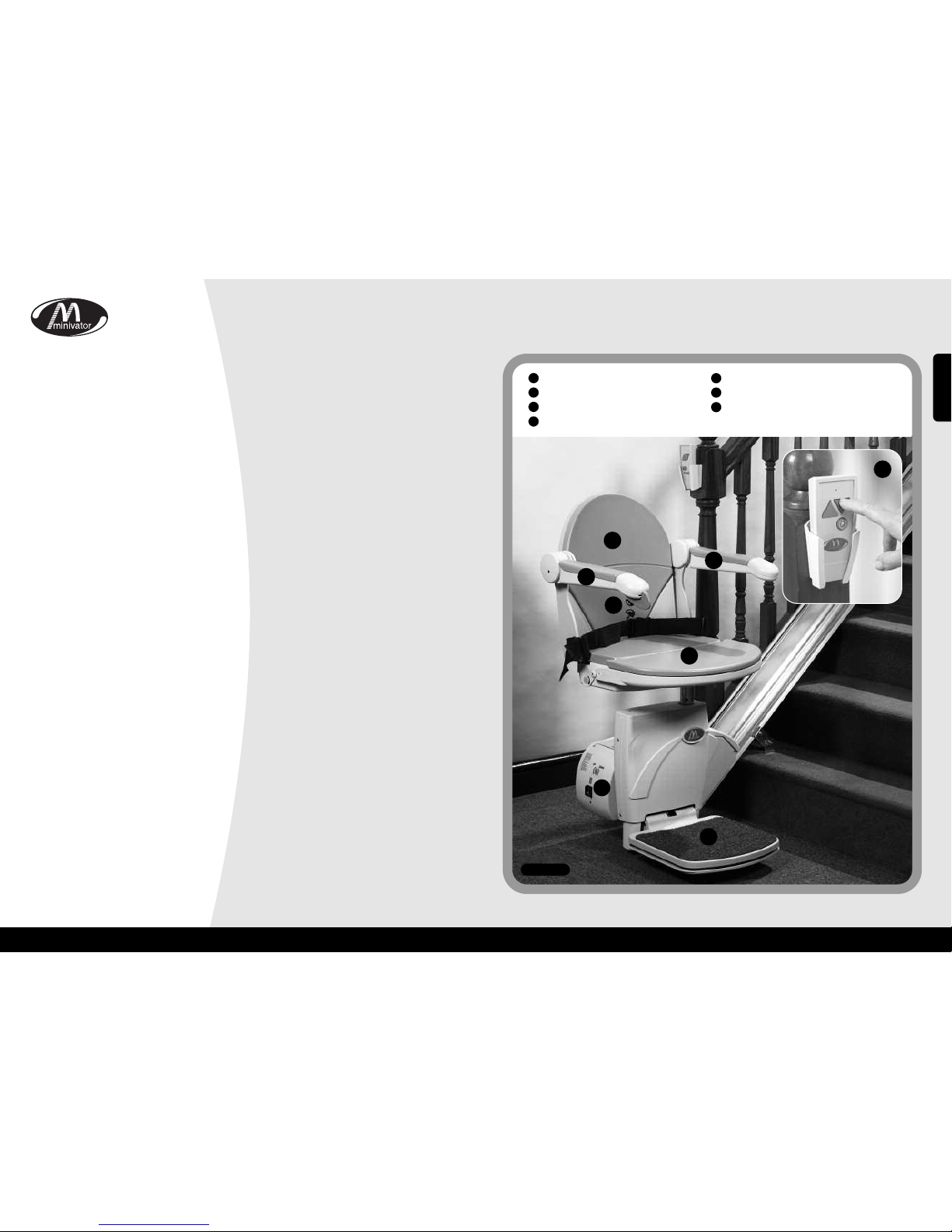
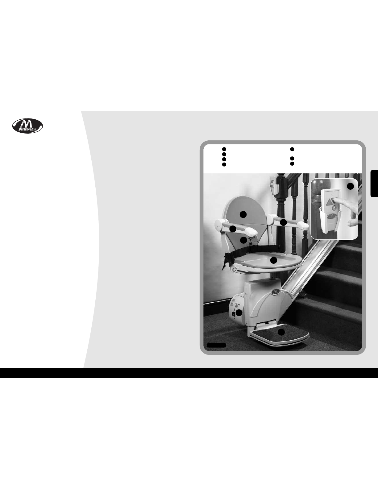
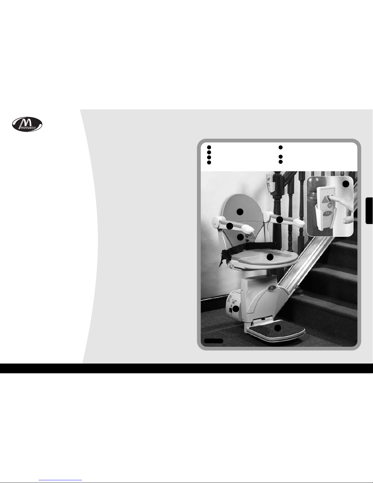
Folding seat
Swivel seat
Infra red remote control
Folding footrest with safety edges
Simple to operate key switch control
Folding armrests
Diagnostic display
1
2
3
4
5
6
7
1
2
3
4
5
6
6
7
Figure 1
Features of your Minivator Simplicity+ 950
ENGLISH
Page 3
Operating your Minivator Simplicity+ 950
Operating your Minivator Simplicity
+ 950
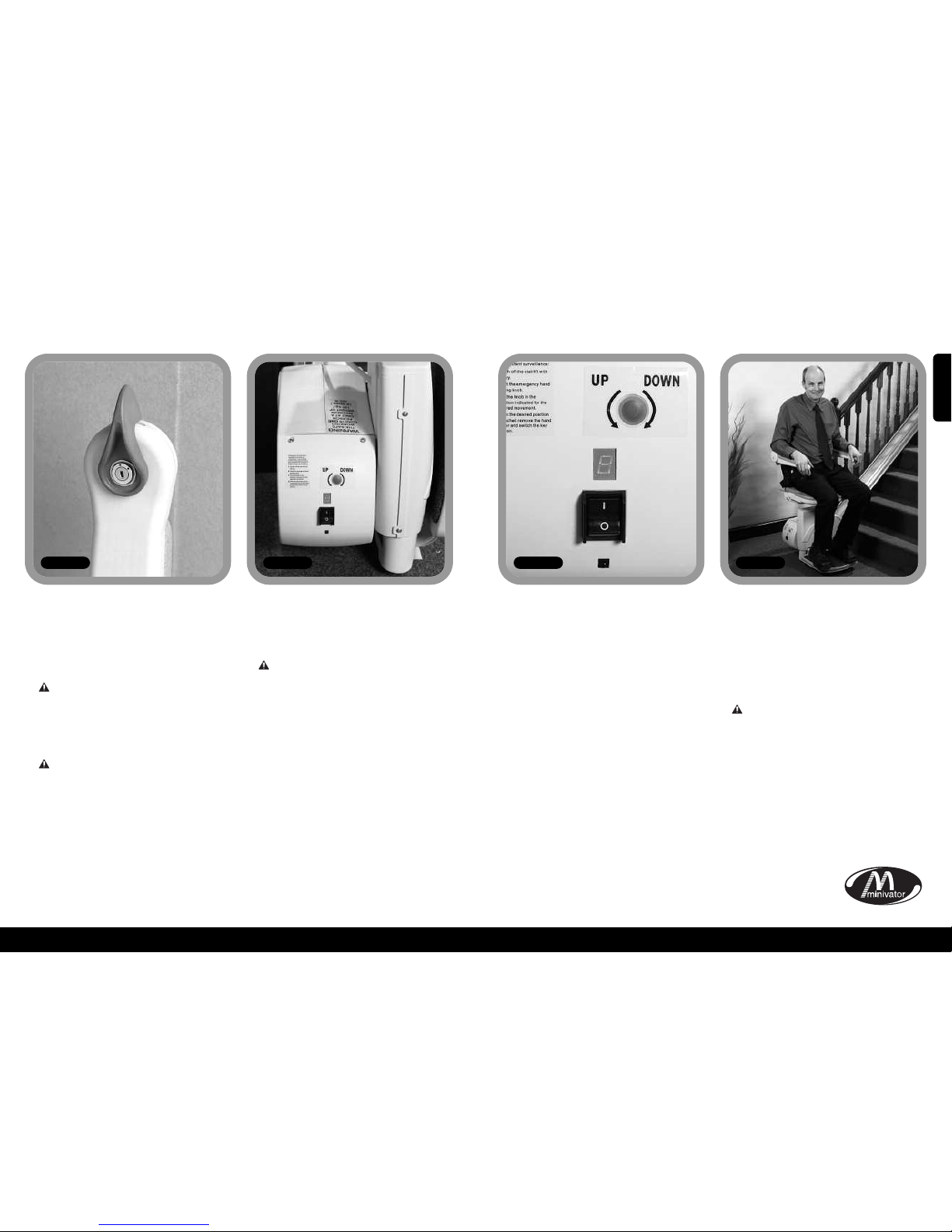
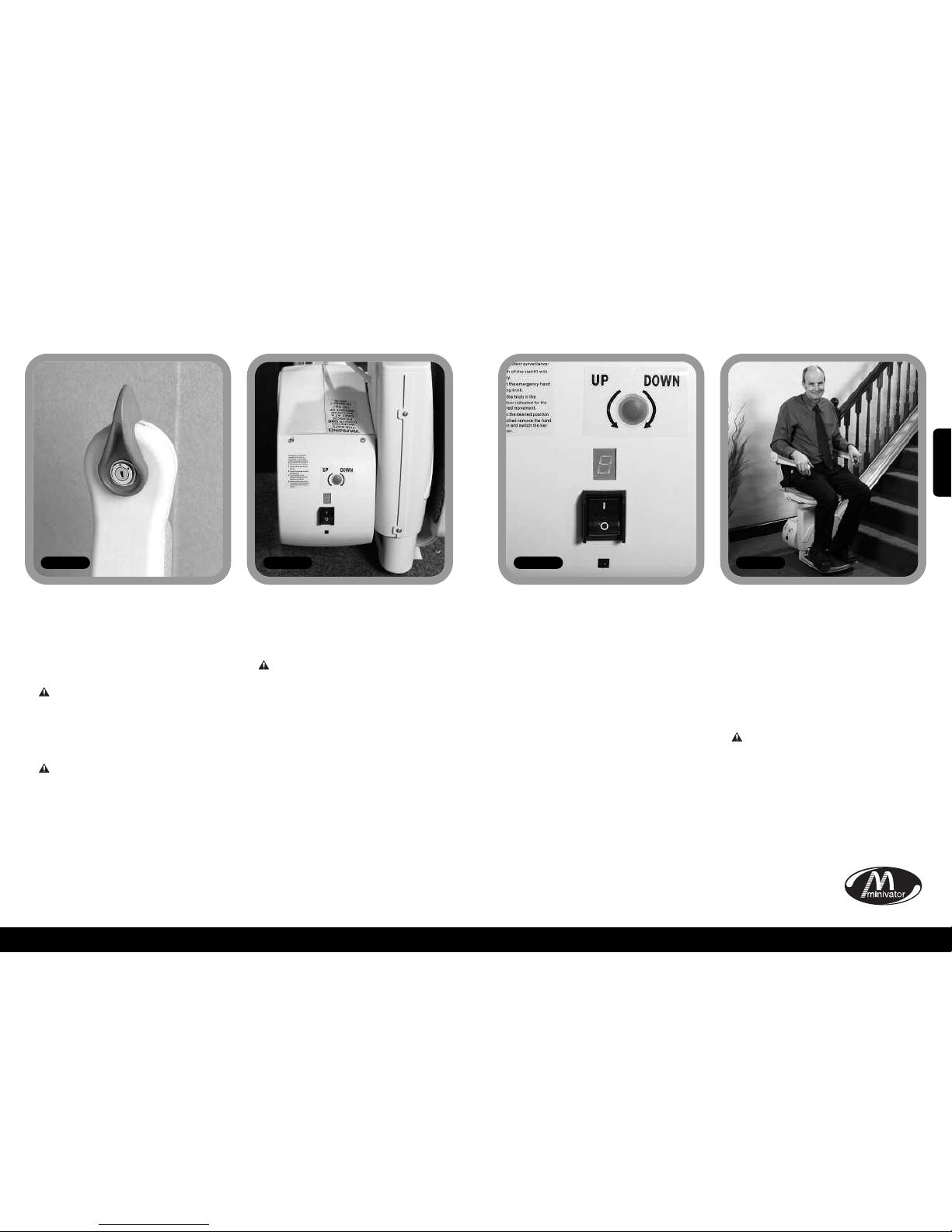
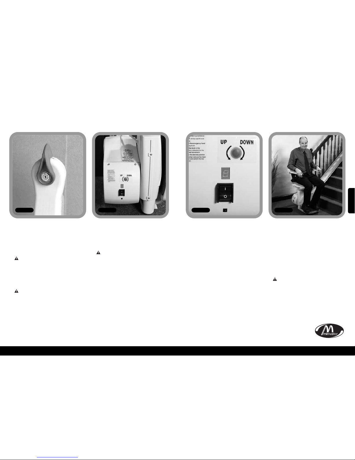
Your Minivator stairlift is fitted with a key
switch (Figure 2).
The stairlift cannot be operated unless the
key is inserted and turned to the on
position.
The keyswitch is provided to enable
you to lock the stairlift to prevent it
being used by others (for example
children).
However, it can be left in the on position if
desired.
If you remove your key for safety
reasons, please ensure you put it in a
safe place.
If the keyswitch is turned off the lift will
continue to charge.
As well as a key switch your stairlift is fitted
with an on/off switch (Figure 3) on the
bottom, side panel of the lift.
Ensure that this is left in the ‘ON’
position. The fault diagnosis display
panel will be illuminated to indicate
this.
If you intend to be away from home for a
long period, and decide to switch off the
mains supply, it is important that you also
switch off the lift from this on/off switch.
This will ensure that the lift batteries will
remain charged while you are away.
Before use
Before using your stairlift, MOST
IMPORTANTLY please ensure the stairs are
clear of other people, pets or any objects
which may obstruct your stairlift. Then
ensure that the arms, footplate and seat
are folded down for use to ensure your
safety (Figure 5).
BEFORE OPERATING YOUR
STAIRLIFT ALWAYS FASTEN
YOUR LAP BELT.
4
Key switch On/off switch
3
Figure 2 Figure 3 Figure 4 Figure 5
Diagnostic display
The stairliftis fitted with a diagnostic display
(Figure 4) that displays a code to help
diagnose faults. Refer to Appendix 1 for
an explanation of the diagnostic codes. If
you should experience a problem with
your lift please examine the display and
make a note of any codes that are
displayed. Please inform the customer
services operator of these codes when
reporting any fault.
ENGLISH
Page 4
6
5
Operating your Minivator Simplicity+ 950
Operating your Minivator Simplicity
+ 950
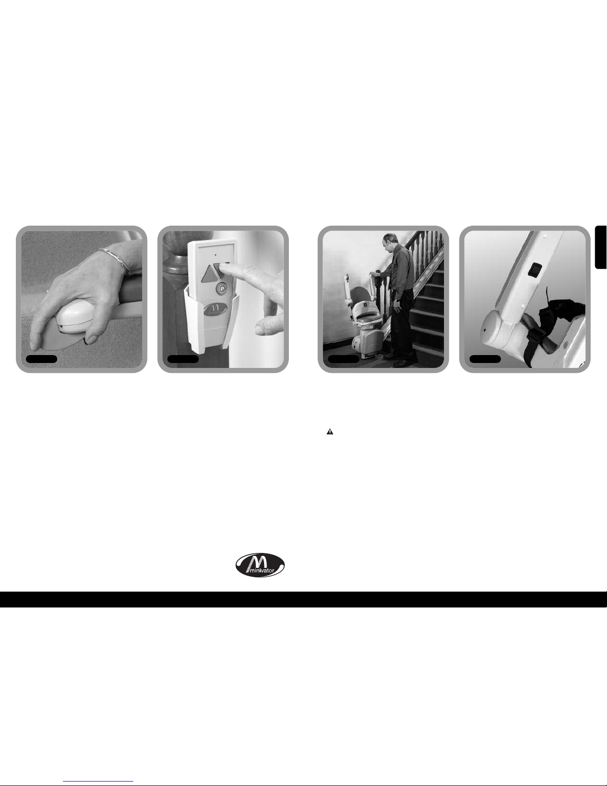
Operating toggle
Figure 6
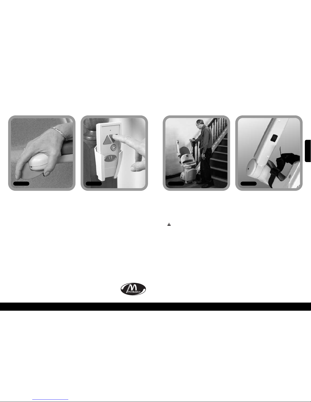
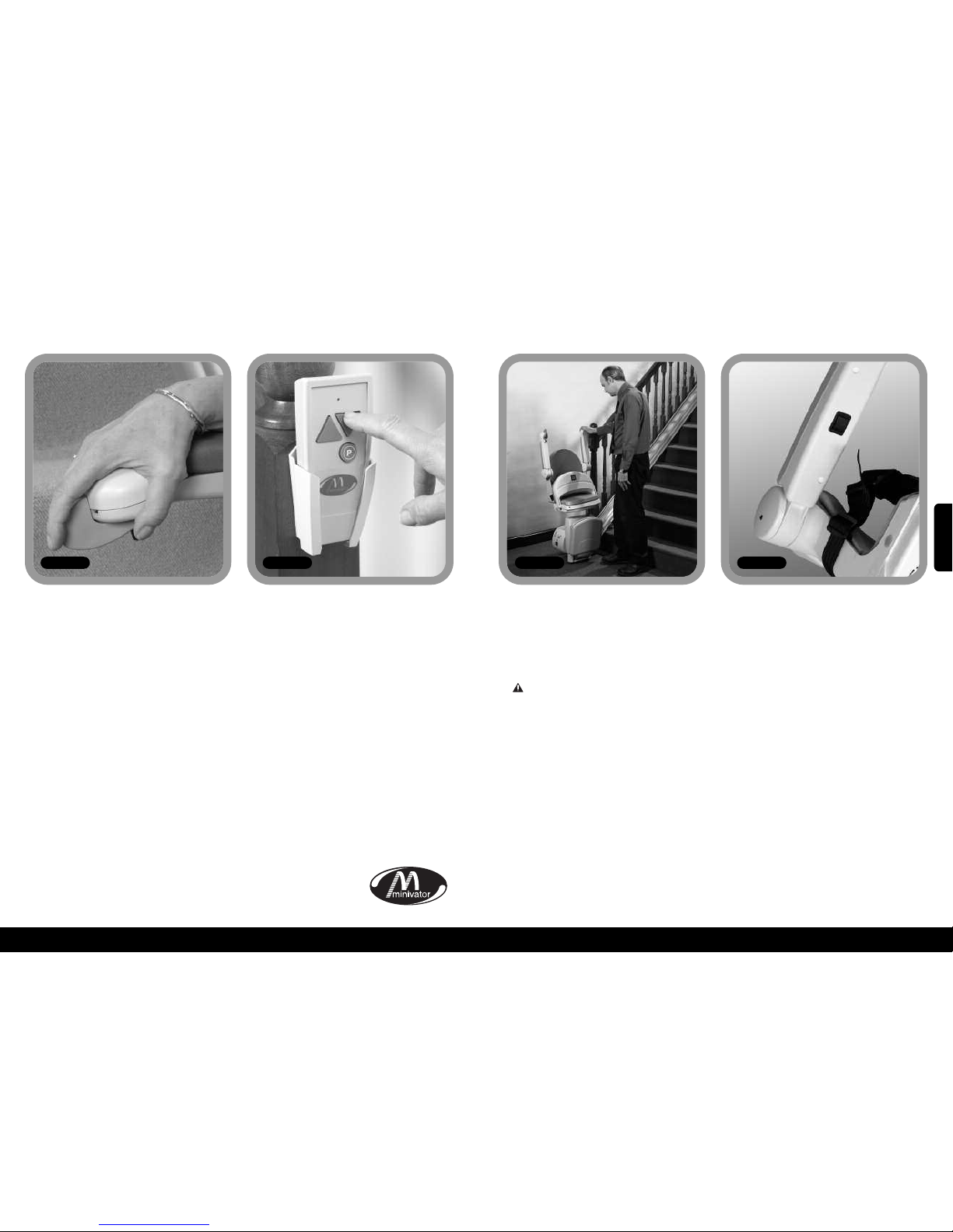
The remote control (Figure 7) is used to
call the lift to either the top/bottom of the
stairs or to operate a powered folding
hinge where fitted. This control may also
be used by an attendant where the user is
unable to operate the stairlift themselves.
The attendant should always remain off
the staircase until the stairlift is stationary.
Your Minivator Simplicity+ 950 seat,
armrests and footrest can be folded to
allow easier passage up and down stairs
when it is not in use (Figure 8).
SAFETY PRECAUTION!
ALWAYS RETURN THE STAIRLIFT TO ITS
STOWED POSITION. I.E. WITH ARMRESTS,
SEAT AND FOOTREST FOLDED AND THE
CHAIR PARALLEL TO THE TRACK AS
SHOWN IN FIGURE 8, SO THAT EXITS ARE
NOT OBSTRUCTED.
Manual footplate link (optional)
If your stairlift is fitted with a manual
footplate link the footplate will
automatically fold away when the front
seat squab is lifted. It will also lower the
footplate when the front seat squab is
lowered.
Power footplate link – seat squab
operated (optional)
If your stairlift is fitted with a power
footplate link operated from the seat
squab it will automatically fold away the
footplate when the front seat squab is
lifted. It will also lower the footplate when
the front seat squab is lowered.
Power footplate link – arm operated
(optional)
If your stairlift is fitted with a power
footplate link operated from the arm it will
have an additional switch under the arm
(Figure 9). To lower the footplate, use the
rocker switch under the arm. To lift the
footplate move the rocker switch to its
alternate position.
NB If movingthe footplatewhile seated on
the stairlift please ensure your feet do not
obstruct the footplate whilst it is in motion.
Remote control
Folding your stairlift
Figure 7 Figure 8
Your Minivator stairlift is operated by
simply pressing and holding the operating
toggle in the direction you wish to travel
(Figure 6). The stairlift will automatically
stop when the toggle is released or the
stairlift has reached the end of its travel.
PLEASE NOTE:
In the interest of safety, initial activation of
the stairlift is delayed by 1 second from
pressing and holding the operating toggle,
to avoid accidental operation. If the toggle
is released while the lift is in motion, the
lift will stop and a delay of 1 second will
occur before the toggle will re-start the lift.
When changing the direction of travel the
delay will be 3 seconds before the lift
begins to move.
Figure 9
ENGLISH
Page 5
8
7
Operating your Minivator Simplicity+ 950
Operating the swivel
Figure 10
A swivel seat is provided to enable you to
mount/dismount the seat more easily at
the top of the stairs by swivelling you on to
the landing.
To operate the seat swivel, wait until
the stairlift has stopped.
To swivel the seat hold either (there is one
both sides of the seat) swivel lever down
or pull it up. This will release the seat lock
and allow you to move the seat round by
pushing away from the footplate. When
the seat reaches 90 degrees it will lock in
position.
You should not attempt to leave the seat
until it has firmly ‘clicked’ into its locked
position.
To swivel in the opposite direction follow
the same procedure, but push away from
the landing.
Power operated swivel (optional)
If your stairlift is fitted with an optional
power operated swivel there will be no
swivel levers fitted. In order to swivel the
seat hold the operating toggle in the up
direction. When the stairlift reaches the
top of the stairs continue to hold the
operating toggle in the up direction.
The stairlift will beep three times and then
the seat will swivel. When the seat
is fully swivelled to 90 degrees the seat will
stop.
You should not attempt to leave the seat
until it is fully rotated.
To swivel in the opposite direction follow
the same procedure in reverse. Push the
operating lever in the down direction. The
seat will beep three times and then after a
short pause it will rotate to the driving
position. Continue to hold the operating
lever in the down direction. The stairlift
will then again beep three times before
beginning its descent.
SAFETY PRECAUTIONS
NEVER
Swivel the seat without the lap belt
fastened.
NEVER
Mount or dismount the swivel seat unless it
is locked in position.
NEVER
Try to operate the swivel seat whilst the
stairlift is in motion. (As a safety precaution,
should you try to use it whilst the lift is in
motion, it will cause the lift to stop).
NEVER
Attempt to travel up or down the staircase
unless the seat is in the correct position (i.e.
facing directly across the staircase).
Operating your Minivator Simplicity+ 950
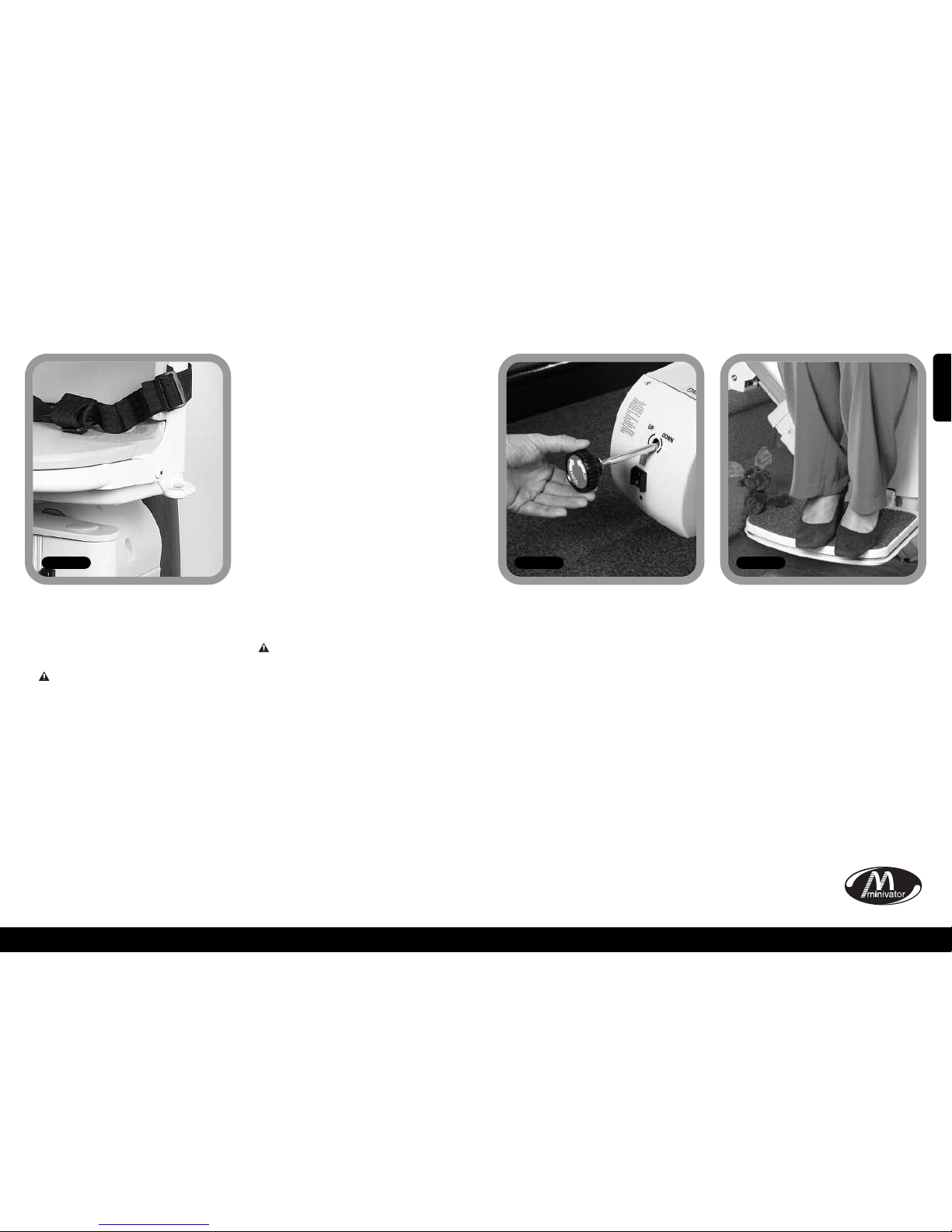
In the unlikely event that the lift has a
total power failure or runs on to the final
track stops there is an emergency hand
winding procedure. Please follow these
steps:
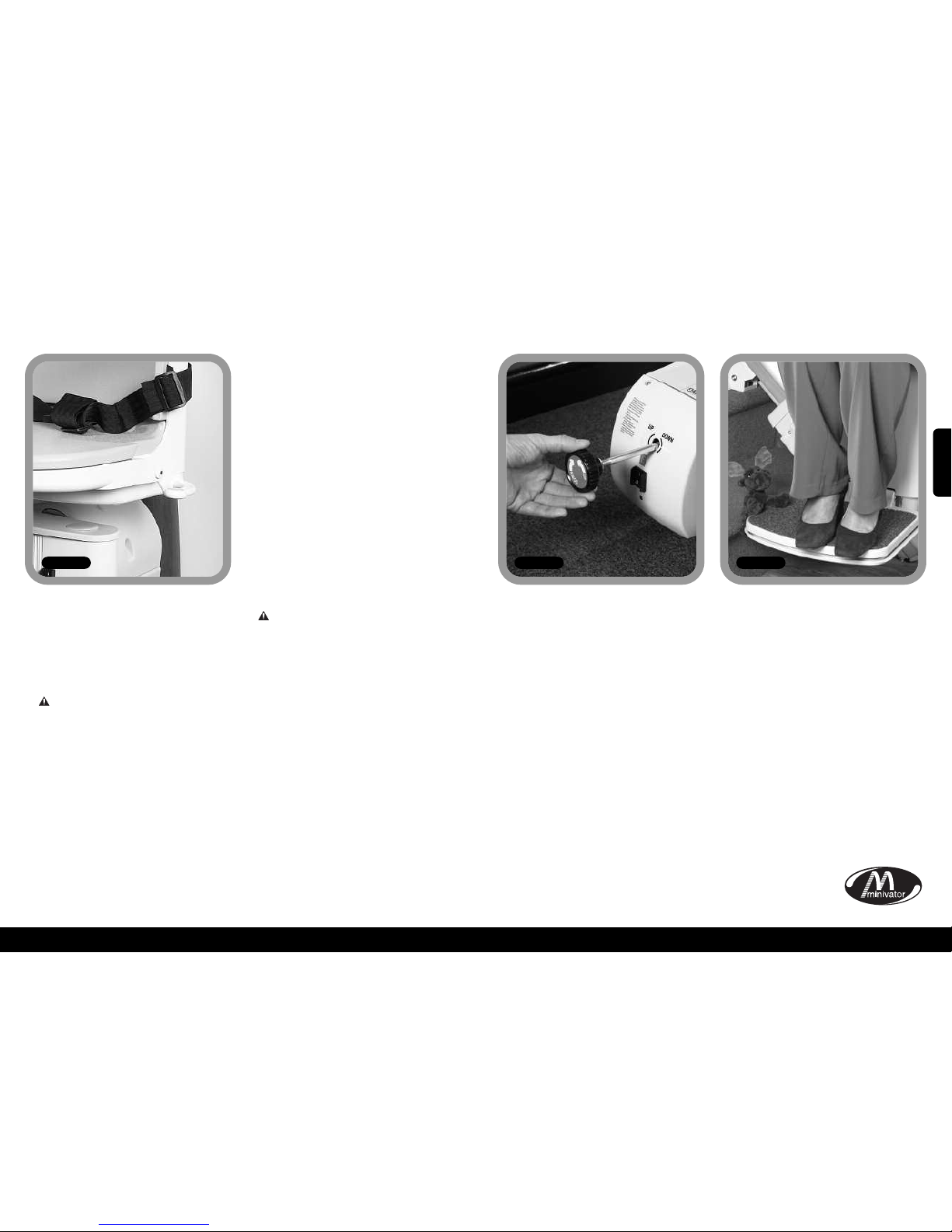
1. Switch off the stairlift with the key.
2. Insert the emergency hand winding
knob (Figure 11).
3. Turn the knob in the direction indicated
for the required movement.
4. When the desired position is reached
remove the hand winder and switch the
lift on.
If in any doubt contact your local
Minivator approved dealer or ring
Minivator direct on 08700 118282.
Your stairlift is fitted with safety edges
on the bottom of the footrest and on the
lift itself that will stop the stairlift should
any article become trapped by the footrest
(Figure 12).
To remove the article reverse the stairlift
away from the object then have the object
removed from the staircase. Proceed on
your stairlift as normal.
Emergency hand
winding instructions
Trapped articles
Figure 11 Figure 12
ENGLISH
Page 6

10
9
xSafety and servicingx
We advise that your stairlift is serviced after the first 12 months and thereafter AT LEAST EVERY
12 MONTHS.
This work must be carried out by a competent person, i.e. a Minivator approved dealer.
If in doubt, please contact the Minivator Service Department on 08700 118282.
If you own your stairlift and no longer require it your dealer or Minivator may be interested in
purchasing it.
Warnings and precautions
NEVER
Allow more than one person to use the stairlift at any one time.
The maximum carrying capacity is 120kg (19 Stone / 265lb).
NEVER
Allow children to play on or with the stairlift.
NEVER
Allow water to come into contact with the components in the stairlift. If you have to
transport liquids DO SO WITH CARE.
NEVER
Place objects in the track or leave objects on the stairs, where they could come into contact
with the lift in operation. Your stairlift is fitted with pressure sensitive side edges and
undertray on the footplate, which will automatically stop the lift if it detects any
obstructions.
NEVER
Use the stairlift without using the lap belt, or any other safety belts or harnesses fitted.
NEVER
Use the stairlift in a standing position.
ALWAYS
Keep your FEET ON THE FOOTPLATE whilst the stairlift is in motion, and try to avoid your
feet hanging over the edges of the footplate.
NEVER
Swivel the seat until the lift has come to a stop at the top or bottom of the staircase.
ALWAYS
Fold the chair when it is not in use to avoid obstructing exits.
WARNING
If the overspeed governor is activated it should only be reset by a competent person, i.e. a
Minivator approved dealer. Activation of the overspeed governor is indicated by the lift not
being able to be driven down the stairs and the diagnostic display showing 0.
xRoutine care and maintenancex
Battery care
and charging
Your Minivator stairlift is battery powered
and will continue to work for a period of
time even if you have a power cut. You
should normally be able to travel up and
down the stairs at least 10 times without
needing to charge the batteries.
Particularly in the event of a power cut,
however you should always ensure that
there is sufficient light to allow safe travel,
and especially at each end of the track
where you get on and off the lift.
Your stairlift track is fitted with charging
points, normally at the top and bottom of
the staircase. Your stairlift should be left on
one of these charging points when not in
use to ensure that the batteries are
charged. If the stairlift makes a beeping
noise and/or the display show a "2" when
it is left on a charging point and it is not in
use IT IS NOT CHARGING. Please check that
the power supply for the stairlift is
switched on. If it is switched on and the
beeping continues please contact your
dealer or the Minivator Service Department
on 08700 118282.
Maintenance
There are no user serviceable parts fitted to
your stairlift. If any damage is visible or
your stairlift sounds or behaves unusually
contact Minivator or your approved dealer
immediately. We advise that your stairlift is
serviced after the first 12 months and
thereafter AT LEAST EVERY 12 MONTHS.
Care and cleaning
Before cleaning any part of your Minivator
stairlift, please ensure you have removed
the key.
The Minivator stairlift is manufactured
from a variety of materials, all with easy
“wipe clean” surfaces. The seat and body
covers can be wiped over with a damp,
NOT WET, cloth and a small quantity of
washing up liquid.
PLEASE DO NOT use abrasive cleaners,
bleach or solvent based cleaners, as these
will damage the seat.
To clean the track, first send the stairlift to
the top of the stairs. The track can be
cleaned with a damp cloth. When most of
the track is clean, move the stairlift to the
bottom of the stairs and finish cleaning the
track making sure that none of the
cleaning debris falls on to it.
To maintain your Minivator stairlift in
good
mechanical order, it is recommended
that
regular services are carried out by qualified
service engineers.
Disposal of
your Stairlift
Your stairlift has been manufactured using
high quality materials and components,
which can be recycled and reused.
The crossed-out wheeled bin
symbol indicates that your
stairlift is covered by the
European Directive 2002/96/EC,
which governs the disposal of
waste electrical and electronic equipment.
This means that your stairlift should not be
disposed of as household waste but should
be appropriately disposed of
for recycling.
Recycling this product will help to protect
the environment by ensuring that all
materials contained in the stairlift are
appropriately handled.
Please contact Minivator on 08700 118282,
your dealer or your local civic office for
further disposal information.
ENGLISH
Page 7
12
11
11
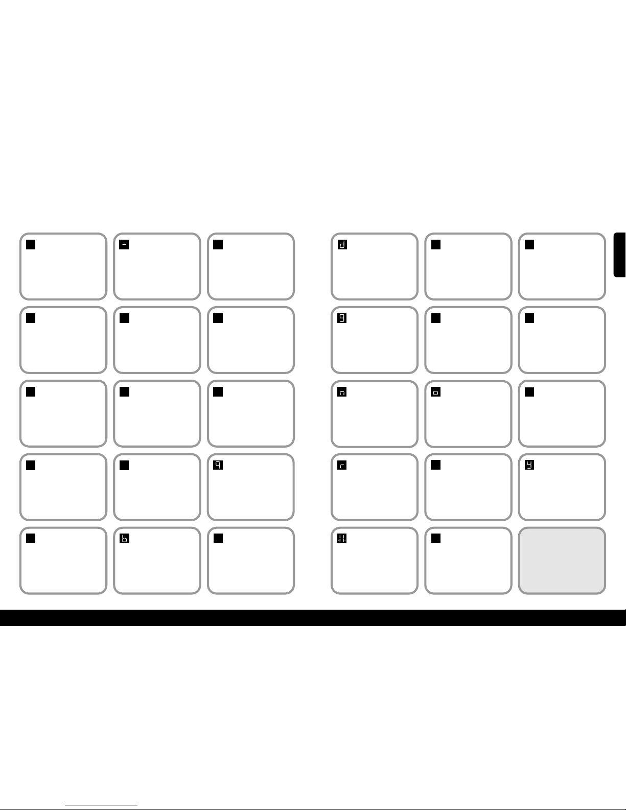
xAppendix 1 – Diagnostic displayx
Code:
None
Meaning:
No display.
Self help action:
Press the toggle switchand see if
display comes on. Check that the main
power switch on the lift is turned on. If
this does not clear the fault, contact
your dealer or Minivator.
Code:1Meaning:
Requires charge.
Self help action:
The stairlift batteries require charging.
Drive the lift to the charge contacts – if
the 'Okay’ code does not show contact
your dealer or Minivator.
Code:
Okay
Meaning:
Okay.
S
elf help action:
Contact your dealer or Minivator.
Code:0Meaning:
Final limit activated
or cable short circuit.
Self help action:
Check that the keyswitch is on and
seat is fully swivelled to the drive
position. If this does not clear the fault,
contact your dealer or Minivator.
0
1
Code:
4
Meaning:
Safety edge (up/down
direction) activated –
footplate.
Self help action:
Contact your dealer or Minivator.
4
Code:
5
Meaning:
Ends limit activated.
Self help action:
Contact your dealer or Minivator.
5
Code:7Meaning:
Batteries approaching
critical level.
Self help action:
The stairlift batteries require charging.
Drive the lift to the charge contacts if the ’Okay’ code does not show
contact your dealer or Minivator.
7
Code:9Meaning:
Shows when toggle
switch is activated in
down/up direction.
Self help action:
N/A.
Code:
6
Meaning:
Safety edge (up/down
direction) activated –
footplate.
Self help action:
Contact your dealer or Minivator.
6
Code:2Meaning:
Off charge.
Self help action:
The stairlift is not parked on a charging positionor is
not charging. Drive the lift to the charge contacts – if
the 'Okay’codedoes not show or the lift is alreadyon
the chargecontacts check the power supply is on.
Failing this contact your dealer or Minivator
.
Code:3Meaning:
Ends limit activated.
Self help action:
Contact your dealer or Minivator.
2
3
Code:AMeaning:
Hinge open.
Self help action:
Contact your dealer or Minivator.
Code:8Meaning:
Shows when toggle
switch is activated in
up/down direction.
Self help action:
N/A.
8
A
Code:bMeaning:
A switch is active at
power on i.e. Toggle
Up, Toggle Down, IR
Up, IR Down or Learn.
Self help action:
Contact your dealer or Minivator.
Code:CMeaning:
The IR address
(dip switch) does not
match
.
Self help action:
Contact your dealer or Minivator.
C
12
Code:dMeaning:
The main power relay
is welded closed.
Self help action:
Contact your dealer or Minivator.
Code:
E
Meaning:
The main power relay
did not close.
Self help action:
Contact your dealer or Minivator.
E
Code:FMeaning:
Brake semi-conductor
failed.
Self help action:
Contact your dealer or Minivator.
f
Code:gMeaning:
Brake not connected.
Self help action:
Contact your dealer or Minivator.
Code:HMeaning:
The main power relay
has closed early.
Self help action:
Contact your dealer or Minivator.
H
Code:LMeaning:
Current limit
exceeded.
Self help action:
Contact your dealer or Minivator.
l
Code:nMeaning:
Half speed.
Self help action:
If permanently showing contact your
dealer or Minivator.
Code:oMeaning:
The main control
board has a memory
problem.
Self help action:
Contact your dealer or Minivator.
Code:
P
Meaning:
Poweredswivel did
not respond.
Self help action:
Contact your dealer or Minivator.
P
Code:rMeaning:
No charge current.
Self help action:
Make sure that power supply is
switched on from mains. If it is contact
your dealer or Minivator.
Code:
N/A
Meaning:
Over current.
Self help action:
Contact your dealer or Minivator.
Code:
N/A
Meaning:
Lift is in "sleep
mode" to conserve
battery power.
Self help action:
Press toggle or handset button to
wake lift.
Code:UMeaning:
Faulty power supply.
Self help action:
Contact your dealer or Minivator.
u
Code:YMeaning:
The main control
board has a software
fault.
Self help action:
Contact your dealer or Minivator.
NOTE: If the display is
showing anything but the
diagnostic codes listed it
requires resetting.
Drive the lift off the charge
contacts. Turn the main switch on
the unit off for 10 seconds and
then back on.
.8.
ENGLISH
Page 8
14
13
xAppendix 2 – Wiring diagramsxxAppendix 2 – Wiring diagramsx
CHASSIS BOTTOM EDGE
CHASSIS UNDERPAN
FOOTREST
BOTTOM EDGE
FOOTREST TOP EDGE
FOOTREST UNDER
PAN SAFE EDGE
FOOTPLATE TO
CHASSIS CONNECTOR
CHASSIS TOP EDGE
SEAT TO CHASSIS
CONNECTOR
TO SEAT CONNECTOR
TO
FINAL
LIMIT
M
F
M
F
F
CONVERSION
LOOM
TRACK
OVERRUN
HINGE/PLATFORM
COMMS DATA
CONTACT
POWER SWIVEL
CONNECTION
(POWERED OPTIONS ONLY)
OSG
F
F
M
MFM
F
TRACK
BOTTOM LIMIT
TRACK
TOP LIMIT
TO
CONVERSION
LOOM
SW5
SW1
SW6
SW14
WHITE
W
HITE
GREY
SPADE
S
PADE
SPADE
BULLET
BULLET
RING
TERMINAL
CONNECTOR
9
WAY CONNECTOR 8 WAY CONNECTOR
SPADE
WHITE
YELL TAG
YELL TAG
SW13
SW8
VIOLET
VIEW FROM
CABLE SIDE
SW7
SW2
SW3
SW4
BROWN
BROWN
RED
TAG
BLUE
TAG
BLUE
TAG
RED
TAG
BLACK
BLUE
SW10
SW9
RED
RED
RED
BROWN
BROWN
VIOLET
VIOLET
VIOLET VIOLET
VIOLET
VIOLET
RED BROWN
GREY
VIOLET
GREY
VIOLET LOOP
GREY
CABLE
SPLICE
CABLE
SPLICE
SEE R/H
CIRCUIT
SEE R/H
CIRCUIT
BROWNBROWN
ORANGE
GREEN
BLUE
GREEN
ORANGE
WHITE
WHITE
DOWN DIRECTION GREEN
3 WAY
CONN
3 WAY
CONN
INFRARED
SENSORS
3 WAY
CONN
TOGGLE COMMON BLUE
UP DIRECTION ORANGE
CHASSIS TOP SAFE-EDGE BROWN
SAFE-EDGE COMMON GREY
CHASSIS BOTT SAFE EDGE VIOLET
BOTT-ENDLIMIT BLACK
BOTT-ENDLIMIT BLACK
TOP-END LIMIT BLUE
TOP-END LIMIT BLUE
FINAL LIMIT WHITE
1
1
12345
6
1
1 2 3
4 5 6
23456
2
2
1
1
1
1
2
3
1
1
1
2
3
4
5
6
7
8
1
1
1
2
3
2
+
5A
SHIELDEDCABLE
DIAGNOSTIC
DISPLAY
BK
+++
+
–
–––
–
BK
BATT
BATT
BATT
BATT
BATT
BATT
BATT
R
ED
M2MOTOR
M1MOTOR
I
R-1
IR-2
H
INGEFUSED
H
INGEDATA
DIAG
C
HRG
CON-1
CON-1
CON-1
CON-2
CON-2
CON-2
CON-3
CON-3
CON-3
CON-3
CON-3
CON-3
CON-3
234567823456789
2
2
1
1
2
2
1
1
2
2
1
1
1
1
1 1 1 1 1 1
2
2
221
1
CHARGE POSITIVE
INPUT VOLTAGE
CHARGE NEGATIVE
THROUGH CHASSIS
MOTOR
BRAKE
15A
Q
UICKBLOW
F
USE
+24V
POWER FOOTPLATE
POWER SUPPLY
BATTERY
ISOLATION
BATTERY
PACK
DISCONNECT
BLACK
BLACK
SW16
WHITE
BLACK
RED
RED
SPADE
BK2
BK1
2
M+
M–
1 2
1
1
M F
PUSH-ON CONNECTOR
KEY:
= MULTI-PINCONNECTOR
ALL SAFETY CIRCUITS SHOULD BE
NORMALLYCLOSED
FUNCTION OF DIP SWITCHES
ON SMT PCB
DIP 1
HALFSPEED UP
H
ALFSPEED DN
PINGDISABLE
A
UTO PLAT DISABLE
A
UTO HINGE DISABLE
S
TANDARD
S
LOW RAMP
U
NUSED
ON
1
2 3 4
DIP 2
FULLSPEED UP
FULLSPEED DN
PING ENABLE
A
UTO PLAT ENABLE
AUTOHINGE ENABLE
FAST RAMP
UNUSED
ON
1
2 3 4
1 1
1
2
3
4
5
6
1
2
3
4
5
6
COMMON
CHASSIS BOTTOM EDGE
CHASSIS UNDERPAN
FOOTPLATE TO
CHASSIS CONNECTOR
CHASSIS TOP EDGE
SEAT TO CHASSIS
CONNECTOR
TO SEAT CONNECTOR
TO
FINAL
LIMIT
M
F
M
F
F
CONVERSION
LOOM
TRACK
OVERRUN
HINGE/PLATFORM
COMMS DATA
CONTACT
POWER SWIVEL
CONNECTION
(POWERED OPTIONS ONLY)
OSG
F
F
M
MFM
F
TRACK
BOTTOM LIMIT
TRACK
TOP LIMIT
TO
CONVERSION
LOOM
SW5
SW1
SW6
SW14
WHITE
WHITE
G
REY
SPADE
SPADE
SPADE
BULLET
BULLET
RING
TERMINAL
CONNECTOR
9
WAY CONNECTOR 8 WAYCONNECTOR
SPADE
WHITE
YELL TAG
YELL TAG
CSE1
SW13
SW8
VIOLET
VIEW FROM
CABLE SIDE
SW7
SW2
SW3
SW4
BROWN
BROWN
BROWN
BROWN
RED
TAG
BLUE
TAG
BLUE
TAG
RED
TAG
BLACK
BLUE
S
W10
SW9
RED RED
RED
BROWN
VIOLET
VIOLET
VIOLET
VIOLET
VIOLET
RED
BROWN BROWN
GREY
VIOLET
GREY
BROWN LOOP
GREY
CABLE
SPLICE
CABLE
SPLICE
SEE L/H
CIRCUIT
SEE L/H
CIRCUIT
BROWN
ORANGE
ORANGE
B
LUE
GREEN
GREEN
WHITE
WHITE
DOWN DIRECTION GREEN
3 WAY
CONN
3 WAY
CONN
INFRARED
SENSORS
3 WAY
CONN
TOGGLE COMMON BLUE
UP DIRECTION ORANGE
CHASSIS TOP SAFE-EDGE BROWN
SAFE-EDGE COMMON GREY
CHASSIS BOTT SAFE EDGE VIOLET
BOTT-ENDLIMIT BLACK
BOTT-ENDLIMIT BLACK
TOP-END LIMIT BLUE
TOP-END LIMIT BLUE
FINAL LIMIT WHITE
1
1
12345
6
1
1 2 3
4 5 6
23456
221
1
1
1
2
3
1
1
1
2
3
4
5
6
7
8
1
11
2
3
2
+
5A
SHIELDEDCABLE
DIAGNOSTIC
DISPLAY
BK
+++
+
–
–––
–
BK
BATT
BATT
BATT
BATT
BATT
BATT
BATT
R
ED
M2MOTOR
M1MOTOR
IR-1
IR-2
HINGE FUSED
H
INGE DATA
DIAG
CHRG
CON-1
CON-1
CON-1
CON-2
CON-2
CON-2
CON-3
CON-3
CON-3
CON-3
CON-3
CON-3
CON-3
234567823456789
2
2
1
1
2
2
1
1
2
2
1
1
1
1
1
1 1 1 1
1
2
2
2
2
1
1
MOTOR
BRAKE
1
5A
QUICKBLOW
F
USE
+24V
POWER FOOTPLATE
POWER SUPPLY
BATTERY
ISOLATION
BATTERY
PACK
DISCONNECT
BLACK
BLACK
SW16
WHITE
BLACK
RED
RED
SPADE
B
K2
BK1
2
M+
M–
1 2
1
1
FOOTREST
TOP EDGE
FOOTREST BOTTOM EDGE
FOOTREST UNDER
PAN SAFE EDGE
CHARGE POSITIVE
INPUT VOLTAGE
CHARGE NEGATIVE
THROUGH CHASSIS
M F
PUSH-ON CONNECTOR
KEY:
= MULTI-PINCONNECTOR
ALL SAFETY CIRCUITS SHOULD BE
NORMALLYCLOSED
FUNCTION OF DIP SWITCHES
ON SMT PCB
DIP 1
H
ALFSPEED UP
HALFSPEED DN
P
ING DISABLE
A
UTO PLAT DISABLE
AUTO HINGE DISABLE
S
TANDARD
SLOW RAMP
U
NUSED
ON
1
2 3 4
DIP 2
F
ULLSPEED UP
FULLSPEED DN
P
ING ENABLE
A
UTO PLAT ENABLE
A
UTO HINGE ENABLE
F
AST RAMP
U
NUSED
ON
1
2 3 4
1 1
1
2
3
4
5
6
1
2
3
4
5
6
COMMON
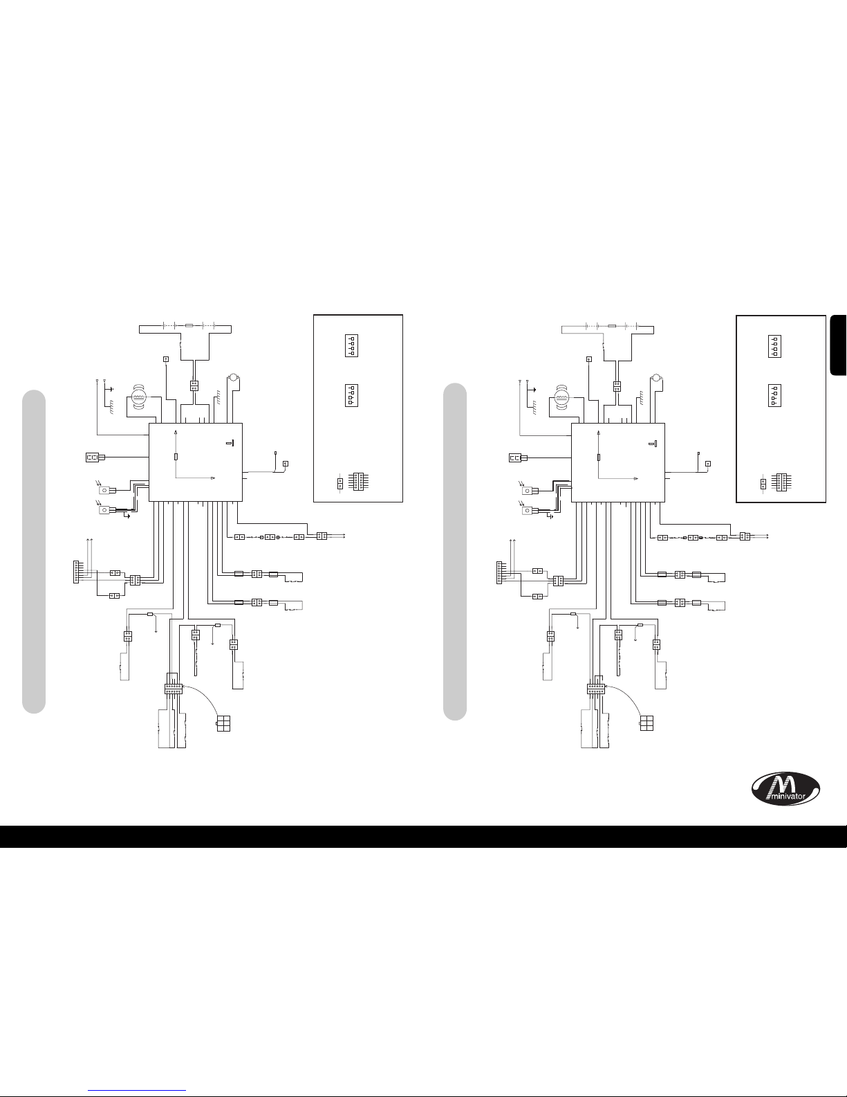
Simplicity+ block schematic – left hand stairlift
Simplicity+ block schematic – right hand stairlift
ENGLISH
ENGLISH
Page 9
15
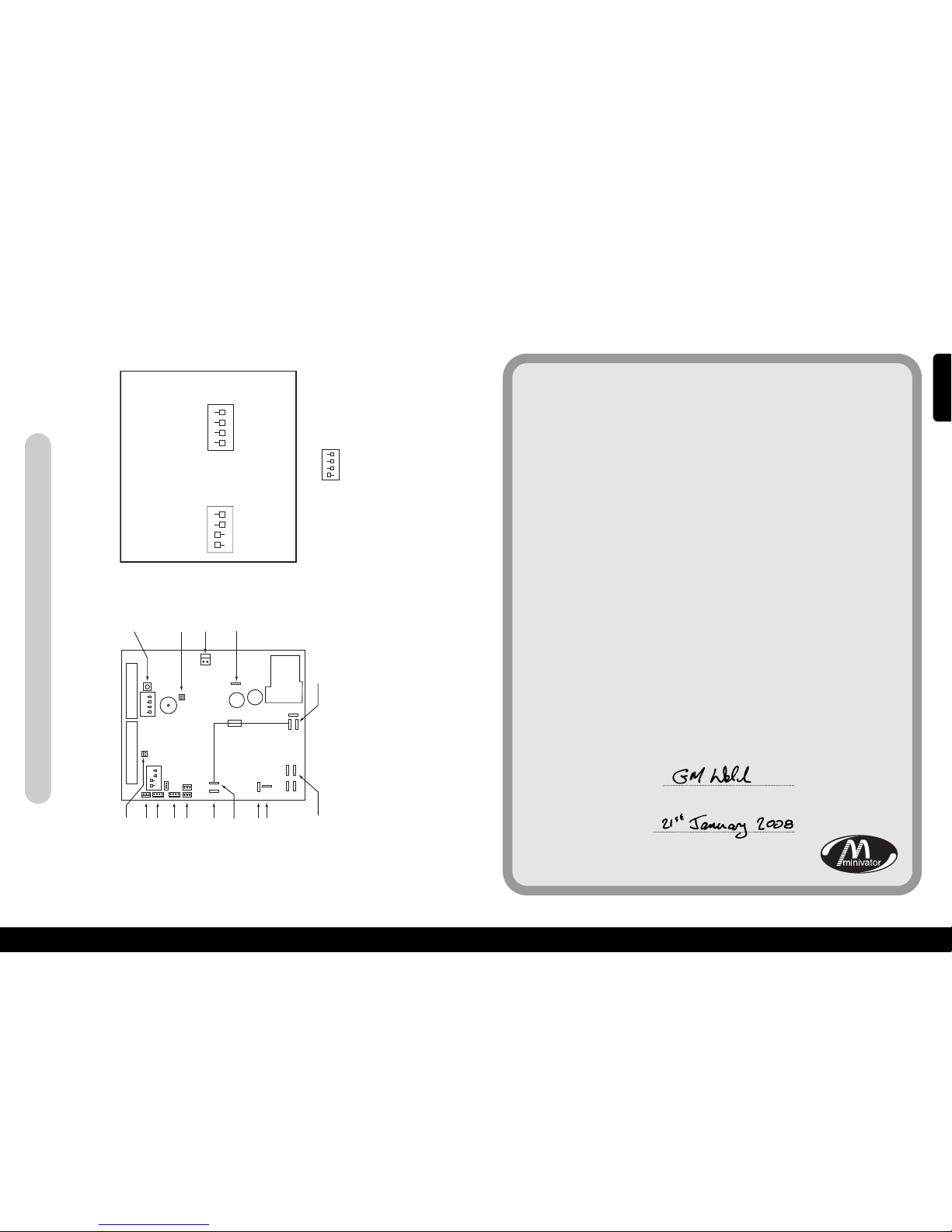
xAppendix 2 – Wiring diagramsx
16
15
INFRARED/RADIO
LEARN BUTTON
NO CONNECTION
REQUIRED
BRAKE CONNECTOR
CHARGE +
BATTERY POSITIVE
BATTERY NEGATIVE
MOTOR 1 (BLACK)
MOTOR 2 (WHITE)
+24V FUSED
HINGE DATA(GREY CABLE)
DIP SWITCH 1
5A
QUICK BLOW
DIP SWITCH 2
NO CONNECTION REQUIRED
7 SEGMENT DISPLAY
NO CONNECTION
REQUIRED
9 WAY CONNECTOR
ON
ON
1 2 3 4
1 2 3 4
8 WAY CONNECTOR
INFRARED/RADIO
IF ANY DIP SWITCHES ARE CHANGED, PLEASE TURN OFF LIFT,
WAIT 10 SECONDS, THEN POWER THE LIFT BACK ON.
DIP 1
ON
1
2 3 4
DIP 2
ON
1
2 3 4
KEY:
DIP SWITCH SETTING CSE126 (POWER SWIVEL BOARD)
THIS SETTING WILL ENABLE POWER SWIVEL MODE
ON
1
2 3 4
HALF SPEED UP
HALF SPEED DOWN
PING DISABLE
PLATFORMDISABLE
H
INGE DISBLE
LEFT HAND LIFT
SLOW RAMP
U
NUSED
FULL SPEED UP
F
ULL SPEED DOWN
PING ENABLE
PLATFORM ENABLE
HINGE ENABLE
RIGHT HAND LIFT
F
AST RAMP
U
NUSED
xAppendix 3 – Certificate of Conformityx
We
Minivator Ltd
of
82 First Avenue
Pensnett Estate
Kingswinford
West Midlands
DY6 7FJ, England.
Declare under our sole responsibility that the product
Minivator Simplicity+ 950 Stairlift
has been manufactured in conformity with the following
standards and specification:
BS5776:1996 Powered Stairlifts
ISO 9386-2 2000-11-01
To which this declaration relates is in conformity with the following
national standards:
Electro Magnetic Compatibility Directive 89/336/EEC
Low Voltage Directive – 73/23/EEC
Machinery Directive – 98/37/EEC
Signed:
Name: G. Welch
Date:
Position: Engineering Manager
Simplicity+ Left Hand and Right Hand Standard
ENGLISH
Page 10
17
Important information about your stairlift which
should be completed by the installation engineer.
Installed by: (Company Name)
Serial No
Date of installation
First service due
Dealer Stamp
18
ENGLISH
Page 11
Vielen Dank, dass Sie sich für unseren
Minivator Treppenlift entschieden haben.
Bitte lesen Sie sie diese Gebrauchsanleitung
sorgfältig durch. Ihr Minivator Treppenlift
ist ein Präzisionsgerät, dass für Sie sorgfältig
entworfen und gebaut wurde. Damit Sie
viele Jahre Ihr Produkt ohne Störungen und
Schwierigkeiten nutzen können, sollten Sie
die Anleitungen bezüglich der Wartung und
der Sicherheit mit besonderer Sorgfalt lesen
und beachten. Minivator empfiehlt, dass Sie
nur die in diesem Handbuch aufgeführten
Routinewartungsarbeiten und die Reinigung
selbst ausführen und die grundlegende Wartung
einem qualifizierten Techniker überlassen.
Bitte setzen Sie sich mit Ihrem Minivator
Händler oder unserer Kundendienstabteilung
unter der Telefonnummer 08700 118282 in
Verbindung, wenn Ihr Treppenlift gewartet
werden muss. Wir helfen Ihnen gerne weiter.
Britische
Standardnormen
Minivator unterliegt dem internationalen
Standard für Industrienormen der durch das
ISO 9001 Prüfsiegel beglaubigt und
zugelassen ist.
Alle Minivator Treppenlifte werden gemäß
der Britischen Standards für Treppenlifte
(BS5776) :1996 und ISO 9386-2 gebaut und
getestet. Sie tragen auch das CE Prüfsiegel.
Minivator Produkte werden fortwährend
auf dem ISO 9001 Standard geprüft und
Sie können sicher sein, dass sie stets ein
qualitativ hochwertiges und
zuverlässiges Produkt benutzen.
Einführung 19
Britische Normen 19
Ausstattung Ihres 20
Minivator Simplicity
+950
Betrieb Ihres 21
Minivator Simplicity
+950
Schlüsselschalter 21
Ein/Aus Schalter 21
Prüfanzeige 22
Vor der Inbetriebnahme 22
Steuerhebel 23
Fernsteuerung 23
Treppenlift zusammenklappen 24
Handhabung des Drehsitzes 25
Anleitung für den Gebrauch
der Notfallkurbel 26
Hindernisse 26
Sicherheit und Kundendienst
27
Hinweise und Vorsichtsmaßnahmen 27
Routinewartung und
Reinigung 28
Batteriewartung und Laden 28
Wartung und Reinigung 28
Entsorgung Ihres Treppenlifts 28
Anhang 1 29
– Prüfanzeige
Anhang 2 31
– Schaltpläne
Anhang 3 34
Technisches Gutachten
19
Einführung
20
Seite
1
2
3
4
6
6
7
Abb. 1
Ausstattung Ihres Minivator Simplicity+950
Einfach zu handhabender
Schlüsselschalter
Klappbare Armstützen
Prüfanzeige
5
6
7
Klappsitz
Drehsitz
Infrarot-Fernsteuerung
Klappbare Fußstütze mit
Sicherheitskanten
4
3
2
1
5
DEUTSCH
Page 12
Betrieb Ihres Minivator Simplicity+ 950
Betrieb Ihres Minivator Simplicity
+ 950
Ihr Minivator Treppenlift ist mit einem
Schlüsselschalter ausgestattet (Abb.2).
Der Treppenlift kann erst benutzt werden,
wenn der Schlüssel eingesteckt und zur
Einschaltposition gedreht wurde.
Der Schlüsselschalter dient dem Zweck,
dass Sie Ihren Treppenlift gegen
unbefugte Benutzung (z.B. durch
Kinder) absperren können.
Der eingesteckte Schlüssel kann auch auf
der Einschaltposition stehen bleiben.
Wenn Sie Ihren Schlüssel aus
Sicherheitsgründen abziehen, legen Sie
ihn bitte an einen sicheren Ort.
Wenn der Schlüsselschalter ausgeschaltet
ist, lädt der Lift weiter.
Ihr Treppenlift ist mit einem Schlüsselschalter
und mit einem Ein/Aus Schalter (Abb.3) auf
der Unterseite des Liftes ausgestattet.
Versichern Sie sich, dass der Schalter auf
„EIN“ steht. Die Fehlerprüfanzeige
leuchtet auf, wenn dies angezeigt wird.
Wenn Sie für längere Zeit aus dem Haus
gehen und die Hauptstromversorgung
abschalten, ist es wichtig, dass Sie den Lift
mit dem Hauptschalter ausschalten.
Auf diese Art bleiben die Liftbatterien
geladen.
Vor der Inbetriebnahme
Bevor Sie Ihren Treppenlift in Betrieb
nehmen, vergewissern Sie sich, dass die
Treppen frei von anderen Personen,
Haustieren oder Objekten sind, die den
Treppenlift behindern.
Vergewissern Sie sich, dass die Armlehnen,
die Fußstütze und der Sitz zur Benutzung
aus Sicherheitsgründen heruntergeklappt
sind. (Abb. 5).
VOR DER BENUTZUNG DES
TREPPENLIFTES IMMER DEN
BECKENGURT ANLEGEN.
22
Schlüsselschalter Ein/Aus Schalter
21
Abb. 2 Abb. 3 Abb. 4 Abb. 5
Prüfanzeige
Der Treppenlift ist mit einer Prüfanzeige
(Abb. 4) ausgestattet, die einen Code zur
Fehlersuche und –analyse anzeigt. Schlagen
Sie unter Anhang 1 für die Erklärungen der
Prüfcodes nach. Wenn Sie ein problem bei
Ihrem Lift bemerken, schauen Sie auf die
Anzeige und notieren Sie die angezeigten
Codes. Melden Sie Ihrem Kundendienst
diese Codenummern bei der Fehlermeldung.
DEUTSCH
Page 13
24
23
Betrieb Ihres Minivator Simplicity+ 950
Betrieb Ihres Minivator Simplicity
+ 950
Steuerhebel
Abb. 6
Mit der Fernbedienung (Abb. 7) kann der
Lift an der Treppen von oben/unten geholt
werden oder eine vorhandene
automatische Klappschiene gesteuert
werden. Mit der Fernbedienung kann auch
eine Pflegeperson anstatt des Benutzers
den Lift bedienen.
Die Pflegeperson sollte solange nicht auf
der Treppe sein, bis der Lift zum Stillstand
gekommen ist.
Ihr Sitz, Armlehnen und die Fußstütze
Ihres Minivator Simplicity+ 950 sind
klappbar um bei parkiertem Treppenlift
weiterhin leicht die Treppe nutzen zu
können (Abb. 8).
SICHERHEITSMASSNAHME!
DEN TREPPENLIFT STETS IN DIE
PARKIERUNGSPOSITION BRINGEN. D.H. MIT
ZUSAMMENGEKLAPPTEN ARMLEHNEN,
SITZ UND FUSSTÜTZEN UND DEM SITZ
PARALLELL ZUR SCHIENE GEDREHT WIE
AUF ABBILDUNG 8, SODASS KEINE WEGE
BLOCKIERT WERDEN.
Manuelle Fußstütze Anschluß
(wahlweise)
Wenn Ihr Treppenlift mit einer manuellen
Fußstütze ausgestattet ist, klappt die
Fußstütze automatisch weg, wenn die
Sitzrückenlehne angehoben wird. Beim
Absenken der Sitzrückenlehne wird auch
die Fußstütze ausgeklappt.
Fußstützenautomatik – an der
Sitzrückenlehne (wahlweise)
Wenn Ihr Treppenlift mit einer
Fußstützenautomatik an der Sitzlehne
ausgestattet ist, klappt die Fußstütze
automatisch weg, wenn die
Sitzrückenlehne angehoben wird. Beim
Absenken der Sitzrückenlehne wird auch
die Fußstütze ausgeklappt.
Fußstützenautomatik – an der
Armlehne (wahlweise)
Wenn Ihr Treppenlift mit einer
Fußstützenautomatik mit einem Schalter
an der Armlehne ausgestattet ist (Abb. 9),
wird die Fußstütze mit dem Betätigen des
Schalter unter der Armlehne abgesenkt.
Zum Zusammenklappen der Fußstütze den
Schalter in die andere Richtung legen.
NB Wenn die Fußstütze angehoben/gesenkt
wird während Sie auf dem Treppenlift
sitzen, dürfen Ihre Füße der Platte nicht im
Weg sein.
Fernsteuerung
Treppenlift parkieren
Abb. 7 Abb. 8
Ihr Minivator Treppenlift fährt durch ein
einfaches Drücken und Halten des
Steuerhebels in die gewünschten Richtung
(Abb. 6). Der Treppenlift stoppt
automatisch wenn der Hebel während der
Fahrt losgelassen und braucht 1 Sekunde
Verzögerung bevor der Lift die Fahrt
fortsetzt.
BITTE BEACHTEN:
Aus Sicherheitsgründen verzögert der
Treppenlift das Losfahren um 1 Sekunde
nachdem der Steuerhebel gedrückt und
gehalten wird, um einen unbeabsichtigten
Betrieb zu vermeiden. Der Treppenlift
stoppt automatisch wenn der Hebel
während der Fahrt losgelassen und braucht
1 Sekunde Verzögerung bevor der Lift die
Fahrt fortsetzt.
Bei Richtungswechsel während der Fahrt
beträgt die Verzögerung des Liftes 3
Sekunden.
Abb. 9
Page 14
26
25
Betrieb Ihres Minivator Simplicity+ 950
Gebrauch des
Steuerhebels
Abb. 10
Ein Drehsitz ermöglicht es Ihnen, leichter
oben oder unten an der Treppe
auszusteigen, indem Sie sich zum
Treppenabsatz hin drehen können.
Den Drehsitz erst in Gang setzen, wenn
der Lift abgestoppt hat.
Zum Drehen des Sitzes entweder einen der
beiden Drehhebel (auf beiden Seiten
angebracht) herunterdrücken oder ziehen. Das löst die Sitzsperre und der Sitz
kann von der Fußstütze weg gedreht
werden. Wenn der Sitz 90° erreicht hat,
rastet er wieder in die Position ein.
Der Sitz sollte erst verlassen werden, wenn
der Sitz fest „eingeklickt“ d.h. eingerastet
ist.
Um in die andere Richtung zu drehen, den
Vorgang wiederholen und vom
Treppenabsatz wegdrehen.
Drehstuhl Automatik (Wahlweiss)
Wenn Ihr Treppenlift wahlweise mit einem
Automatikdrehstuhl ausgerüstet ist, hat
dieser keine Hebel. Um den Sitz zu drehen,
den Hebel aufwärts halten. Wenn der
Treppenlift oben an der Treppe
angekommen ist, den Hebel in dieser
Position lassen.
Der Treppenlift piepst dreimal und der Sitz
dreht sich. Wenn der Sitz sich um 90°
gedreht hat, stoppt er ab. Verlassen Sie den
Sitz erst, wenn er voll gedreht hat.
Um in die entgegengesetzte Richtung zu
drehen, den Vorgang genauso
wiederholen. Den Hebel nach unten legen.
Der Sitz piepst dreimal und dreht nach
einer kurzen Pause in die Fahrtrichtung .
Halten Sie den Hebel weiter nach unten.
Der Treppenlift piepst erneut dreimal
bevor er herunterfährt.
!SICHERHEITSHINWEISE
NIEMALS
Den Sitz ohne Sitzgurt drehen.
NIEMALS
Ohne Einrastung den Drehsitz verlassen
oder benutzen.
NIEMALS
Den Drehsitz betätigen, währen der
Treppenlift in Bewegung ist.
(Sicherheitshalber stoppt der Lift ab, sobald
Sie versuchen den Drehmechanismus
auszulösen).
NIEMALS
Nach unten oder hochfahren, solange der
Sitz nicht in der korrekten Position ist (d.h.
in Richtung quer über der Treppe).
Betrieb Ihres Minivator Simplicity+ 950
Im unwahrscheinlichen Fall eines
Stromausfalls des Liftes oder eines
Festhängens des Antriebs oben gibt es
eine Nothandkurbel. Befolgen Sie die
Schritte:
1. Den Treppenlift mit dem Schlüssel
abschalten.
2. Die Nothandkurbel einsetzen (Abb. 11).
3. Drehen Sie die Kurbel in der benötigten
Richtung.
4. Wenn die gewünschte Position erreicht
ist, die Nothandkurbel entfernen und
den Lift anschalten.
Falls Sie Fragen dazu haben, setzen Sie sich
mit dem örtlichen Minivator Händler unter
der Telefonnummer 08700 118282 in
Verbindung.
Ihr Treppenlift ist mit Sicherheitskanten an
der Unterseite des Fußbrettes und am Lift
selbst ausgestattet, die den Treppenlift
anhalten wenn ein Gegenstand sich im
Fußbrett verfängt (Abb. 12).
Um den Gegenstand zu entfernen, den
Treppenlift ein Stück rückwärts weg vom
Objekt bewegen und es von der Treppe
nehmen lassen. Dann die Fahrt mit dem
Lift fortsetzen.
Nothandkurbel
Hindernisse
Abb. 11 Abb. 12
DEUTSCH
Page 15
28
27
xSicherheit und Kundendienstx
Wir empfehlen einen Kundendienstcheck des Liftes nach den ersten 12 Monaten und danach
MINDESTENS ALLE 12 MONATE.
Diese Arbeit sollte von einer dafür qualifizierten Person durchgeführt werden, d.h. einem
anerkannten Minivator Händler.
Wenn Sie dazu Fragen haben, den Minivator-Kundendienst unter der Telefonnummer
08700 118282 anrufen.
Wenn Sie den Treppenlift gekauft haben und ihn nicht mehr benötigen, setzen Sie sich mit Ihrem
Händler oder Minivator in Verbindung. Evtl. kann der Lift weiterverkauft werden.
Hinweise und Sicherheit
NIE
Mehr als eine Person zu selben Zeit den Treppenlift benutzen lassen.
Die maximale Tragkraft beträgt 120kg.
NIE
Kindern erlauben mit oder auf dem Treppenlift zu spielen.
NIE
Die Teile des Treppenlifts nicht mit Wasser in Berührung bringen. Flüssigkeiten VORSICHTIG
damit transportieren.
NIE
Gegenstände auf der Schiene oder auf der Treppe lassen, wo sie mit dem Lift in Berührung
kommen können. Ihr Treppenlift ist mit druckempfindlichen Seitenkanten am Lift und an
der Unterseite des Fußbrettes ausgerüstet, die den Lift automatisch stoppen wenn sie ein
Hindernis orten.
NIE
Den Treppenlift ohne den Sicherheitsgurt, oder den Beckengurt nutzen.
NIE
Den Treppenlift stehend benutzen.
IMMER
Die Füße während der Fahrt AUF DEM FUSSBRETT BEHALTEN und nicht die Füße über das
Fußbrett hinaus hängen lassen.
NIE
Den Sitz drehen bevor der Lift oben oder unten an der Treppe abgestoppt hat.
IMMER
Den Stuhl zusammenklappen wenn er nicht in Gebrauch ist (sonst Hindernis).
WARNUNG
Wenn der Geschwindigkeitsbegrenzer aktiviert wurde, sollte er nur von einer qualifizierten
Person zurückgesetzt werden. Dieser Fall wird dadurch angezeigt, dass der Lift nicht die
Treppe hinunterfährt und die Prüfanzeige die Ziffer 0 anzeigt.
xRoutinechecks und Wartungx
Batteriepflege und
Aufladen
Ihr Minivator Treppenlift ist
batteriebetrieben und kann auch nach einem
Stromausfall eine Zeitlang funktionieren. Im
Normalfall können Sie etwa 10 Mal fahren
bevor die Batterien geladen werden müssen.
Im Falle eines Stromausfalls bitte darauf
achten, dass genügend Licht vorhanden ist,
um besonders oben und unten an der Treppe
einen sicheren Ausstieg/Einstieg zu
gewährleisten.
Ihre Treppenliftschiene ist mit zwei
Ladepunkten ausgestattet – oben und unten
an der Treppe. Der Treppenlift muss bei
Nichtbenutzung an einer dieser Stellen
parkiert werden, um aufzuladen. Wenn er
ein Piepgeräusch macht und /oder eine „2“
auf der Prüfanzeige anzeigt und er nicht in
Betrieb ist LÄDT ER NICHT AUF. Bitte
überprüfen, ob die Stromversorgung für den
Treppenlift eingeschaltet ist. Wenn er
eingeschaltet ist und der Piepton nicht
aufhört, bitte Ihren Minivator Händler oder
den Kundendienst unter der Nummer 08700
118282 anrufen.
Reparaturen
Ihr Treppenlift hat keine für den Nutzer
verwertbaren Teile. Wenn Beschädigungen
sichtbar sind oder das Gerät ungewohnte
Geräusche hervorbringt oder Störungen im
Betrieb zeigt, bitte Ihren Händler oder
Minivator verständigen. Wir empfehlen
einen Kundendienstcheck des Liftes nach den
ersten 12 Monaten und danach MINDESTENS
ALLE 12 MONATE.
Pflege & Wartung
Bevor Sie Ihren Minivator Treppenlift
reinigen, bitte vorher den Schlüssel abziehen.
Ihr Minivator Treppenlift ist mit
verschiedenen, leicht zu reinigenden
Materialien gebaut worden. Der Sitz und die
Verkleidungen können mit einem feuchten,
A
BER NICHT NASSEN, Tuch und etwas
Reinigungsmittel abgewischt werden.
Bitte KEINE Scheuermittel, Bleiche oder
lösungsmittelhaltige Reiniger benutzen,
denn diese beschädigen den Sitz.
Für die Schienenreinigung, den Treppenlift
zum oberen Haltepunkt fahren. Die Schiene
kann mit einem feuchten Tuch abgewischt
werden. Wenn die Schiene dort sauber ist,
den Treppenlift nach unten fahren und die
Schiene reinigen. Dabei sollten keine
Schmutzpartikel in die Schiene fallen.
Damit Ihr Minivator Treppenlift im
einwandfreien technischen Zustand bleibt,
empfehlen wir eine regelmäßige Wartung
durch qualifizierte Techniker.
Entsorgung Ihres
Treppenlifts
Ihr Treppenlift besteht aus hochwertigen
Materialien und Komponenten, die
wiederverwendet werden können.
Das Symbol des durchgestrichenen
Mülleimers bedeutet, dass Ihr
Treppenlift unter die europäische
Abfallrichtlinie Nr. 2002/96/EC,
fällt, die die Entsorgung von
Elektroschrott und elektronischen Geräten
regelt.
Ihr Treppenlift darf nicht im
Hausmüll/Sperrmüll entsorgt werden,
sondern muss dem
Wiederverwertungskreislauf zugeführt
werden.
Wenn das Produkt wiederverwertet wird,
schützen Sie damit die Umwelt und sparen
wertvolle Rohstoffe, aus denen Ihr
Treppenlift hergestellt worden ist, ein.
Die Minivator Telefonnummer 08700 118282,
Ihr örtlicher Händler oder Ihre
Stadtverwaltung informieren Sie gerne über
die Entsorgungrichtlinien.
DEUTSCH
Page 16
12
11
29
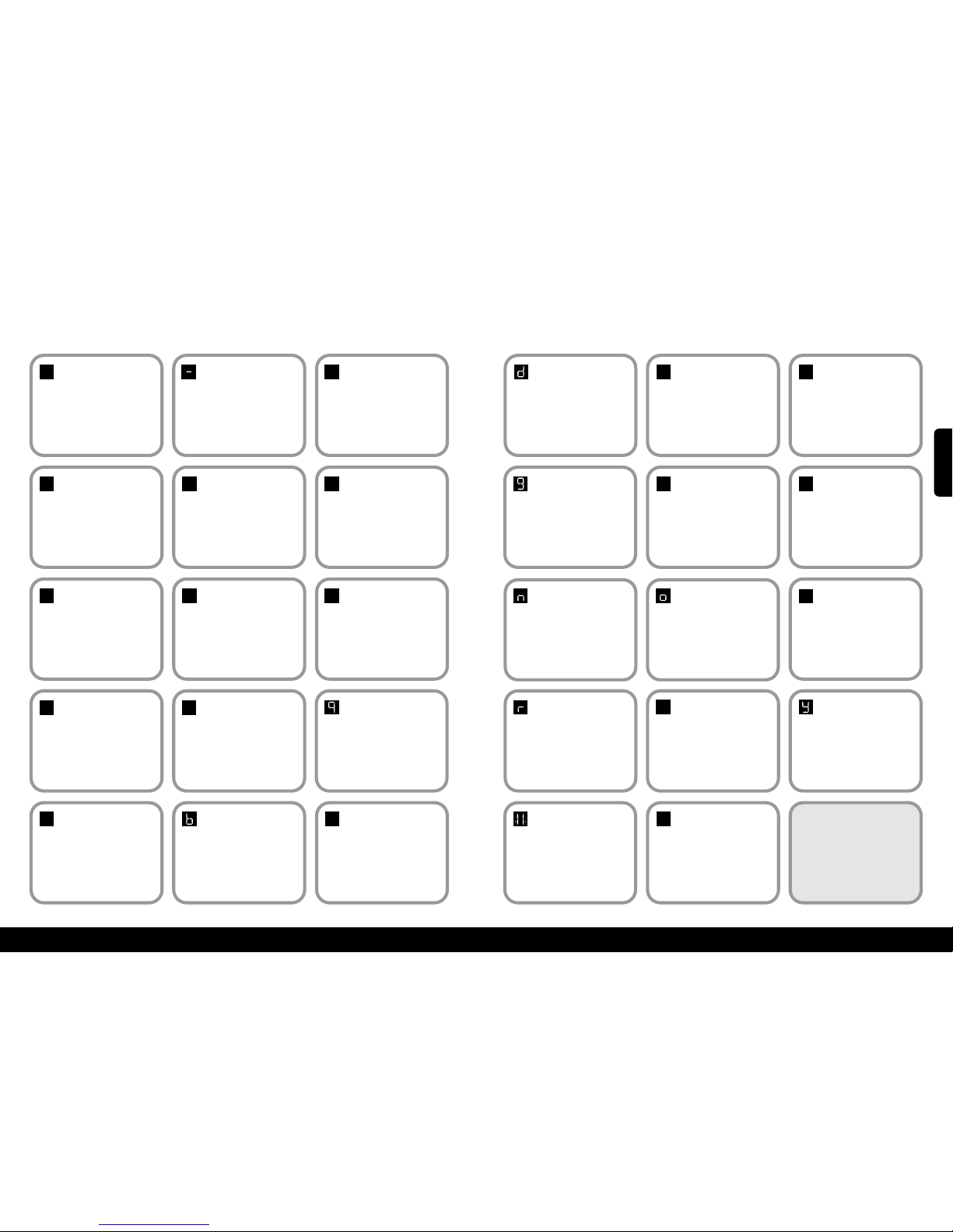
xAnhang 1 – Prüfanzeigex
Code:
Kein
Bedeutung:
Keine Anzeige.
Selbsthilfemaßnahme:
Den Hebel drücken und versuchen das
Display anzuzeigen. Der Hauptschalter
am Lift muss eingeschaltet sein. Wenn
dies den Fehlernicht behebt Ihren
Händler oder Minivator verständigen.
Code:1Bedeutung:
Laden erforderlich.
Selbsthilfemaßnahme:
Die Treppenliftbatterien müssen
aufgeladen werden. Den Lift zu den
Ladepunkten fahren –
Wenn der “Okay” Code nicht angezeigt
wird, Ihren HändleroderMinivatoranrufen.
Code:
Okay
Bedeutung:
Okay.
S
elbsthilfemaßnahme:
Ihren Händler oder Minivator
verständigen.
Code:0Bedeutung:
Überlastung aktiviert
oder.
Selbsthilfemaßnahme:
Überprüfung des Schlüsselschalter und
der korrekten Position des Drehsitzes.
Wenndiesden Fehlernicht behebt Ihren
Händler oder Minivator verständigen.
0
1
Code:
4
Bedeutung:
Sicherheitskante
(aufwärts/abwärts)
aktiv – Fußbrett.
Selbsthilfemaßnahme:
Ihren Händler oder Minivator
verständigen.
4
Code:
5
Bedeutung:
Toleranzgrenze
erreicht.
Selbsthilfemaßnahme:
Ihren Händler oder Minivator
verständigen.
5
Code:7Meaning:
Batteries approaching
critical level.
Selbsthilfemaßnahme:
Die Treppenliftbatterien müssen aufgeladen
werden. Den Lift zu den Ladepunktenfahren
– Wenn der “Okay” Code nicht angezeigt
wird, Ihren Händleroder Minivatoranrufen.
7
Code:9Bedeutung:
Anzeige für Hebel
abwärts/aufwärts.
Selbsthilfemaßnahme:
N/A.
Code:
6
Bedeutung:
Sicherheitskante
(aufwärts/abwärts)
Richtung aktiviertFußsstütze.
Selbsthilfemaßnahme:
Ihren Händler oder Minivator
verständigen.
6
Code:2Bedeutung:
Laden Aus.
Selbsthilfemaßnahme:
Der Treppenlift ist nicht auf einem
Ladepunkt oder lädt nicht. Den Lift zu
den Ladepunkten fahren –
Wenn der “Okay” Code nicht angezeigt
wird, Ihren HändleroderMinivatoranrufen.
Code:3Bedeutung:
Grenze aktiviert.
Selbsthilfemaßnahme:
Ihren Händler oder Minivator
verständigen.
2
3
Code:ABedeutung:
Klappschiene offen.
Selbsthilfemaßnahme:
Ihren Händler oder Minivator
verständigen.
Code:8Bedeutung:
Anzeige für Hebel
abwärts/aufwärts.
Selbsthilfemaßnahme:
N/A.
8
A
Code:bBedeutung:
Schalter ist aktiv.
Selbsthilfemaßnahme:
Ihren Händler oder Minivator
verständigen.
Code:CBedeutung:
Die IR Adresse
(Wippschalter) passt
nicht.
Selbsthilfemaßnahme:
Ihren Händler oder Minivator
verständigen.
C
30
Code:dBedeutung:
Schalter klemmt.
S
elbsthilfemaßnahme:
Ihren Händler oder Minivator
verständigen.
Code:
E
Bedeutung:
Hauptschalter
schliesst nicht ab.
S
elbsthilfemaßnahme:
Ihren Händler oder Minivator
verständigen.
E
Code:FBedeutung:
Bremse fällt aus.
S
elbsthilfemaßnahme:
Ihren Händler oder Minivator
verständigen.
f
Code:gBedeutung:
Bremse nicht
angeschlossen.
Selbsthilfemaßnahme:
Ihren Händler oder Minivator
verständigen.
Code:HBedeutung:
Hauptschalter schaltet
zu früh ab.
Selbsthilfemaßnahme:
Ihren Händler oder Minivator
verständigen.
H
Code:LMeaning:
Current limit
exceeded.
Selbsthilfemaßnahme:
Ihren Händler oder Minivator
verständigen.
l
Code:nBedeutung:
Halbe
Geschwindigkeit.
Selbsthilfemaßnahme:
Wenn dauerhaft, Ihren Händler oder
Minivator verständigen.
Code:oBedeutung:
Speicherproblem an der
Hauptsteuerungsplatine.
Selbsthilfemaßnahme:
Ihren Händler oder Minivator
verständigen.
Code:
P
Bedeutung:
Automatikhebel
reagiertnicht.
Selbsthilfemaßnahme:
Ihren Händler oder Minivator
verständigen.
P
Code:rBedeutung:
Ladestrom.
Selbsthilfemaßnahme:
Hauptschalter muss eingeschaltet sein.
Wenn er es ist, bitte Händler oder
Minivator verständigen.
Code:
N/A
Bedeutung:
Überspannung.
Selbsthilfemaßnahme:
Ihren Händler oder Minivator
verständigen.
Code:
N/A
Bedeutung:
Lift ist im
“Sleepmodus“ um
Batterie zu sparen.
Selbsthilfemaßnahme:
Den Hebel drücken oder die
Handkurbel drehen, um den Lift zu
aktivieren.
Code:UBedeutung:
Stromversorgung
defekt.
Selbsthilfemaßnahme:
Ihren Händler oder Minivator
verständigen.
u
Code:YBedeutung:
Die Hauptsteuerungsplatine hat einen
Softwarefehler.
Selbsthilfemaßnahme:
Ihren Händler oder Minivator
verständigen.
HINWEIS: Wenn die Anzeige
etwas anderes als die
Prüfcodes anzeigt, einen
Reset durchführen.
Den Lift von den Ladepunkten
wegfahren. Den Hauptschalter
etwa für 10 Sekundenausschalten,
und dann wieder einschalten.
.8.
DEUTSCH
Page 17
32
31
xAnhang 2 – Schaltplänex
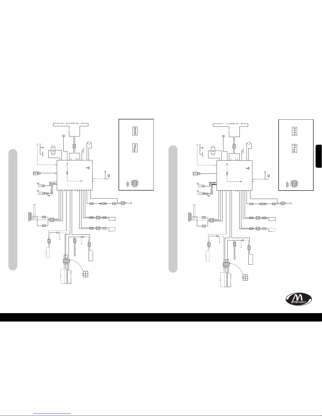
Simplicity+ block schematic – Treppenlift rechts
xAnhang 2 – Schaltplänex
GEHÄUSE UNTERE KANTE
GEHÄUSE BODEN
FUSSABLAGEUNTERE KANTE
FUSSABLAGEUNTERE KANTE
FUSSABLAGEOBERE KANTE
VERBINDUNG FUSSSTÜTZE
ZU GEHÄUSE
GEHÄUSE OBEN KANTE
SITZ AN GEHÄUSE
ANSCHLUSS
ZU SITZ VERBINDUNG
ZU
LIMIT
GRENZE
M
F
M
F
F
UMWANDLUNG
KABELBAUM
SCHIENE
ÜBERSCHUSS
KLAPPSCHIENE/
PLATTFORM
DATENÜBER-
TRAGUNGSKONTAKT
DREHSTUHLAUTOMATIK
ANSCHLUSS
(NUR AUTOMATIK)
OSG
F
F
M
MFM
F
SCHIENE UNTERE
GRENZE
SCHIENE OBERE
GRENZE
ZU
UMWANDLUNG
KABELBAUM
SW5
SW1
SW6
SW14
WEIß
WEIß
G
RAU
FLACHSTECKER
FLACHSTECKER
FLACHSTECKER
SCHRAUBE
SCHRAUBE
KABELSCHUH
ANSCHLUSS
9 WEGE VERBINDUNG 8 WEGE VERBINDUNG
FLACHSTECKER
W
EIß
GELBES
ETIKETT
GELBES
ETIKETT
SW13
SW8
VIOLETT
ANSICHT
KABELSEITE
SW7
SW2
SW3
SW4
BRAUN
BRAUN
ROTES
ETIKETT
BLAUES
ETIKETT
BLAUES
ETIKETT
ROTES
ETIKETT
SCHWARZ
BLAU
SW10
SW9
ROT
ROT
ROT
BRAUN
BRAUN
VIOLETT
VIOLETT
VIOLETT VIOLETT
VIOLETT
VIOLETT
ROT BRAUN
GRAU
VIOLETT
GRAU
STROMSCHLEIFE VIOLETT
GRAU
KABELVERBINDUNG
KABELVERBINDUNG
SIEHE RH
BESCHALTUNG
SIEHE RH
BESCHALTUNG
BRAUNBRAUN
ORANGE
GRÜN
BLAU
GRÜN
ORANGE
WEIß
WEIß
RICHTUNG ABWÄRTS GRÜN
3 WEGE
VERBINDUNG
3 WEGE
VERBINDUNG
3 WEGE
VERBINDUNG
INFRAROTSENSOREN
NORMAL HEBEL BLAU
RICHTUNG AUFWÄRTS ORANGE
GEHÄUSE OBERE SICHERHEITSKANTE BRAUN
SICHERHEITSKANTE NORMAL GRAU
GEHÄUSE UNTERE SICHERHEITSKANTE VIOLETT
UNTEN LIMIT GRENZE SCHWARZ
UNTEN LIMIT GRENZE SCHWARZ
OBEN LIMIT GRENZE BLAU
OBEN LIMIT GRENZE BLAU
END GRENZE WEISS
1
1
12345
6
1
1 2 3
4 5 6
23456
221
1
1
1
2
3
1
1
1
2
3
4
5
6
7
8
1
1
1
2
3
2
+
5A
GESCHIRMTES
KABEL
PRÜFANZEIGE
BK.
+++
+
–
–––
–
BK.
BATT
BATT
BATT
BATT
BATT
BATT
BATT
ROT
M2MOTOR
M1MOTOR
IR-1
I
R-2
KLAPPSCHIENE
S
ICHERUNG
K
LAPPSCHIENE DATEN
D
IAG
L
DG.
ANSCHL-1
ANSCHL-1
ANSCHL-1
ANSCHL-2
ANSCHL-2
ANSCHL-2
ANSCHL-3
ANSCHL-3
ANSCHL-3
ANSCHL-3
ANSCHL-3
ANSCHL-3
ANSCHL-3
234567823456789
2
2
1
1
2
2
1
1
2
2
1
1
1
1
1
1 1 1 1 1
2
2
221
1
POSITIVE LADUNG
EINGANGSSPANNUNG
NEGATIVE LADUNG
EINGANGSSPANNUNG
MOTOR
BREMSE
15A
S
ICHERUNG
+24V
AUTOMATIK FUSSSTÜTZE
STROMVERSORGUNG
BATTERIE-
ISOLIERUNG
AKKULADEEINHEIT
NICHT
VERBUNDEN
SCHWARZ
SCHWARZ
SW16
WEIß
SCHWARZ
ROT
ROT
FLACHSTECKER
BK2
B
K1
2
M+
M–
1 2
1
1
M F
STECKVERBINDUNG
SCHLÜSSEL:
= MULTI-PINANSCHLUSS
ALLE SICHERHEITSSCHALTKREISE
SOLLTENNORMAL GESCHLOSSEN
SEIN.
FUNKTION DER DIP SCHALTERAUF SMT PCB
DIP 1
A
UFWÄRTS HALBE
G
ESCHWINDIGKEIT
A
BWÄRTS HALBE
G
ESCHWINDIGKEIT
P
INGAUSGESCHALTET
A
UTOMATISCHE PLATTFORM
AUSGESCHALTET
A
UTOMATISCHEKLAPPSCHIENE
AUSGESCHALTET
S
TANDARD
R
AMPE LANGSAM
NICHTBELEGT
EIN
1
2 3 4
DIP 2
V
OLLEGESCHWINDIGKEIT
A
UFWÄRTS
VOLLEGESCHWINDIGKEIT
A
BWÄRTS
P
ING EINGESCHALTET
A
UTOMATISCHE PLATTFORM
EINGESCHALTE
T
AUTOMATISCHEKLAPPSCHIENE
E
INGESCHALTET
RAMPE SCHNELL
NICHTBELEGT
EIN
1
2 3 4
1 1
1
2
3
4
5
6
1
2
3
4
5
6
HÄUFIG
M F
STECKVERBINDUNG
SCHLÜSSEL:
= MULTI-PINANSCHLUSS
ALLE SICHERHEITSSCHALTKREISE
SOLLTENNORMAL GESCHLOSSEN
SEIN.
FUNKTION DER DIP SCHALTERAUF SMT PCB
DIP 1
A
UFWÄRTS HALBE
GESCHWINDIGKEIT
A
BWÄRTS HALBE
GESCHWINDIGKEIT
P
INGAUSGESCHALTET
A
UTOMATISCHE PLATTFORM
AUSGESCHALTET
A
UTOMATISCHEKLAPPSCHIENE
AUSGESCHALTET
S
TANDARD
RAMPE LANGSAM
N
ICHT BELEGT
EIN
1
2 3 4
DIP 2
V
OLLEGESCHWINDIGKEIT
AUFWÄRTS
VOLLEGESCHWINDIGKEIT
A
BWÄRTS
P
ING EINGESCHALTET
A
UTOMATISCHE PLATTFORM
E
INGESCHALTET
A
UTOMATISCHEKLAPPSCHIENE
E
INGESCHALTET
RAMPE SCHNELL
N
ICHT BELEGT
EIN
1
2 3 4
1 1
1
2
3
4
5
6
1
2
3
4
5
6
GEHÄUSE UNTERE KANTE
GEHÄUSE BODEN
VERBINDUNG FUSSSTÜTZE
ZU GEHÄUSE
GEHÄUSE OBEN KANTE
SITZ AN GEHÄUSE
ANSCHLUSS
ZU SITZ VERBINDUNG
ZU
LIMIT
GRENZE
M
F
M
F
F
UMWANDLUNG
KABELBAUM
SCHIENE
ÜBERSCHUSS
KLAPPSCHIENE/
PLATTFORM
DATENÜBER-
TRAGUNGSKONTAKT
DREHSTUHLAUTOMATIK
ANSCHLUSS
(NUR AUTOMATIK)
OSG
F
F
M
MFM
F
SCHIENE UNTERE
GRENZE
SCHIENE OBERE
GRENZE
ZU
UMWANDLUNG
KABELBAUM
SW5
SW1
SW6
SW14
WEIß
WEIß
GRAU
FLACHSTECKER
F
LACHSTECKER
FLACHSTECKER
SCHRAUBE
SCHRAUBE
KABELSCHUH
ANSCHLUSS
9 WEGE VERBINDUNG 8 WEGE VERBINDUNG
FLACHSTECKER
WEIß
GELBES
ETIKETT
GELBES
ETIKETT
CSE1
SW13
SW8
VIOLETT
ANSICHT
KABELSEITE
SW7
SW2
SW3
SW4
BRAUN
BRAUN
ROTES
ETIKETT
BLAUES
ETIKETT
BLAUES
ETIKETT
ROTES
ETIKETT
SCHWARZ
BLAU
SW10
SW9
ROT
ROT
ROT
BRAUN
VIOLETT
VIOLETT
VIOLETT
BRAUN
VIOLETT
VIOLETT
ROT
BRAUN BRAUN
GRAU
VIOLETT
GRAU
STROMSCHLEIFE
BRAUN
GRAU
KABELVERBINDUNG
KABELVERBINDUNG
SIEHE LH
BESCHALTUNG
SIEHE LH
BESCHALTUNG
BRAUN
BRAUN
ORANGE
ORANGE
BLAU
GRÜN
GRÜN
WEIß
WEIß
RICHTUNG ABWÄRTS GRÜN
3 WEGE
VERBINDUNG
3 WEGE
VERBINDUNG
3 WEGE
VERBINDUNG
INFRAROTSENSOREN
NORMAL HEBEL BLAU
RICHTUNG AUFWÄRTS ORANGE
GEHÄUSE OBERE SICHERHEITSKANTE BRAUN
SICHERHEITSKANTE NORMAL GRAU
GEHÄUSE UNTERE SICHERHEITSKANTE VIOLETT
UNTEN LIMIT GRENZE SCHWARZ
UNTEN LIMIT GRENZE SCHWARZ
OBEN LIMIT GRENZE BLAU
OBEN LIMIT GRENZE BLAU
END GRENZE WEISS
1
1
12345
6
1
1 2 3
4 5 6
23456
221
1
1
1
2
3
1
1
1
2
3
4
5
6
7
8
1
1
1
2
3
2
+
5A
GESCHIRMTES
KABEL
PRÜFANZEIGE
BK.
+++
+
–
–––
–
BK.
BATT
BATT
BATT
BATT
BATT
BATT
BATT
ROT
M2MOTOR
M1MOTOR
I
R-1
IR-2
K
LAPPSCHIENE
SICHERUNG
K
LAPPSCHIENE DATEN
DIAG
LDG.
ANSCHL-1
ANSCHL-1
ANSCHL-1
ANSCHL-2
ANSCHL-2
ANSCHL-2
ANSCHL-3
ANSCHL-3
ANSCHL-3
ANSCHL-3
ANSCHL-3
ANSCHL-3
ANSCHL-3
234567823456789
2
2
1
1
2
2
1
1
2
2
1
1
1
1
1
1 1 1 1 1
2
2
221
1
MOTOR
BREMSE
1
5A
SICHERUNG
+24V
AUTOMATIK FUSSSTÜTZE
STROMVERSORGUNG
BATTERIE-
ISOLIERUNG
AKKULADEEINHEIT
NICHT
VERBUNDEN
SCHWARZ
SCHWARZ
SW16
WEIß
SCHWARZ
ROT
ROT
BK2
BK1
2
M+
M–
1 2
1
1
FUSSABLAGE OBEN KANTE
FUSSABLAGE UNTERE KANTE
FUSSABLAGE UNTERE
BODEN-SICHERHEITSKANTE
POSITIVE LADUNG
EINGANGSSPANNUNG
NEGATIVE LADUNG
EINGANGSSPANNUNG
FLACHSTECKER
HÄUFIG
Simplicity+ Blockdiagramm – Treppenlift links
DEUTSCH
Page 18
15
xAnhang 2 – Schaltplänex
34
33
INFRAROT/
FUNKVERBINDUNG
TASTE
KEINE
ANSCHLUSSVERBINDUNG
ERFORDERLICH
BREMSE ANSCHLUSS
PLUSPOL LADEN
BATTERIE PLUSPOL
BATTERIE MINUSPOL
MOTOR 1(SCHWARZ)
MOTOR 2 (WEISS)
+24V SICHERUNG
KLAPPSCHIENE DATEN
(GRAUES KABEL)
KEINE ANSCHLUSSVERBINDUNG
ERFORDERLICH
DIP
SCHALTER1
5A
KURZSCHLUSSSICHERUNG
DIP
SCHALTER2
KEINE
ANSCHLUSSVERBINDUNG
ERFORDERLICH
7-TEILIGES DISPLAY
KEINE
ANSCHLUSSVERBINDUNG
ERFORDERLICH
9-WEGE ANSCHLUSS
ON
ON
1 2 3 4
1 2 3 4
8 WEGE ANSCHLUSS
INFRAROT/
FUNKVERBINDUNG
WENN DIP SCHALTER VERÄNDERT WERDEN, DEN LIFT AUSSCHALTEN
10 SEKUNDEN WARTEN, UND WIEDER EINSCHALTEN.
DIP 1
EIN
1
2 3 4
DIP 2
EIN
1
2 3 4
SCHLÜSSEL;
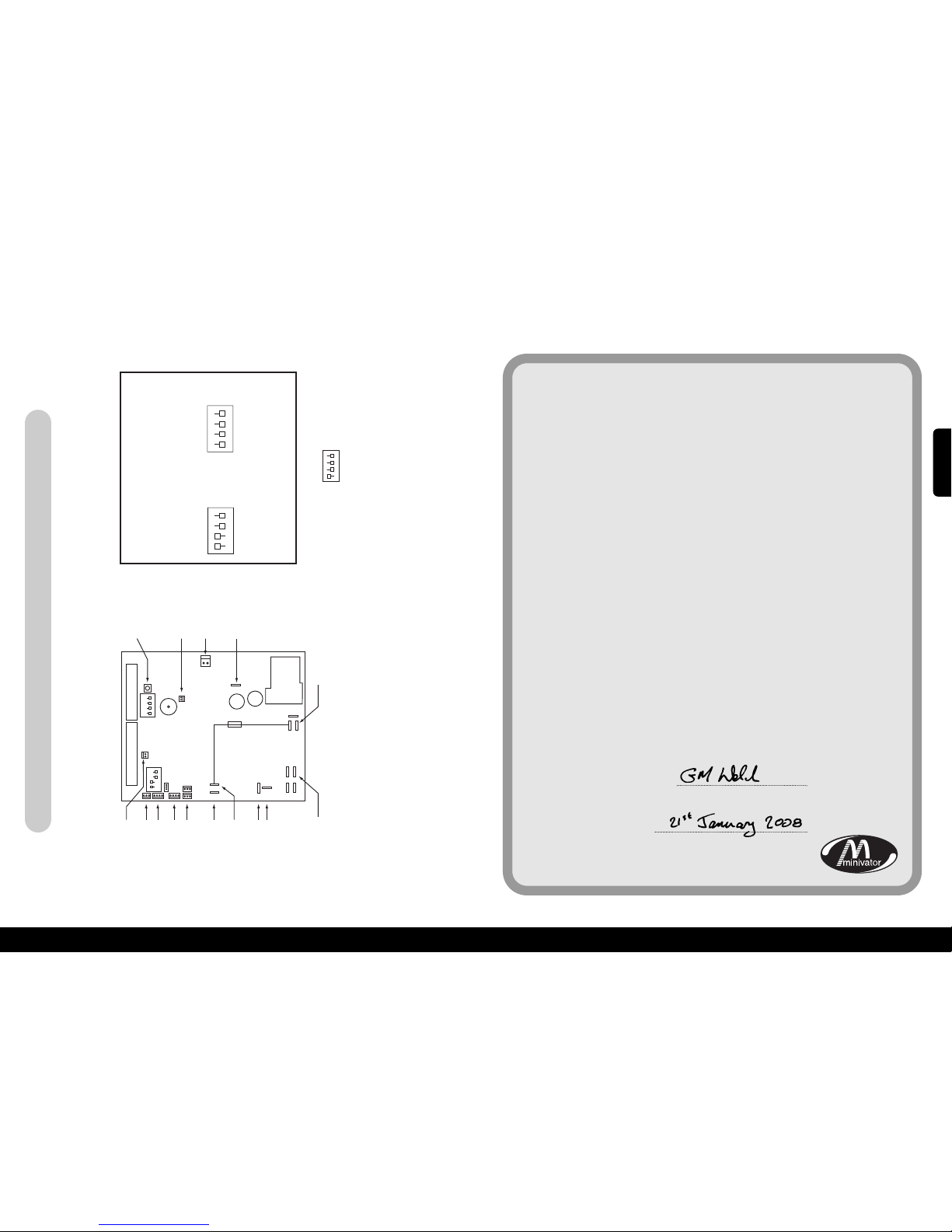
DIP SCHALTER EINSTELLUNG AUF CSE126 (DREHAUTOMATIK-STÜTZE)
DIESE EINSTELLUNG LÄSST DREHAUTOMATIKMODUSZU
EIN
1
2 3 4
HALBE GESCHWINDIGKEIT
AUFWÄRTS
HALBE GESCHWINDIGKEIT
ABWARTS
PING AUSGESCHALTET
P
LATTFORMAUSGESCHALTET
K
LAPPSCHIENE
A
USGESCHALTET
LIFT LINKS
R
AMPE LANGSAM
UNBELEGT
V
OLLE GESCHWINDIGKEIT
AUFWÄRTS
V
OLLE GESCHWINDIGKEIT
ABWARTS
PING EINGESCHALTET
PLATTFORM EINGESCHALTET
K
LAPPSCHIENE
EINGESCHALTET
L
IFT RECHTS
RAMPE SCHNELL
UNBELEGT
xAnhang 3 – Technisches Gutachtenx
Wir
Minivator Ltd
in
82 First Avenue
Pensnett Estate
Kingswinford
West Midlands
DY6 7FJ, England.
stellen auf unsere alleinige Verantwortung hin fest, das das Produkt
Minivator Simplicity+ 950 Treppenlift
In Übereinstimmung mit den folgenden nationalen
Standards hergestellt worden ist:
BS5776:1996 Automatische Treppenlifte
ISO 9386-2 2000-11-01
Ebenso in Übereinstimmung mit den folgenden
nationalen Standards:
Richtlinien zur elektro-magnetischen Verträglichkeit 89/336/EEC
Niederspannungsrichtlinie – 73/23/EEC
Richtlinie Maschinen – 98/37/EEC
Unterschrift:
Name: G. Welch
Datum:
Dienstgrad: Ingenieur
Simplicity+ Links * Rechts Standard/Drehsitzautomatik
Page 19
35
Wichtige Information über Ihren Treppenlift, die Ihr
Monteur ausfüllen sollte.
Montiert von (Firma Name)
Serien Nr
Datum der Montage
Erster Kundendienst
Stempel Händler
36
Page 20
Merci d’avoir choisi un monte-escaliers
Minivator. s’il vous plaît lisez
attentivement ces instructions de
fonctionnement. Votre monte-escaliers
Minivator a été conçu et fabriqué avec
une attention particulière aux détails.
Pour avoir de nombreuses années
d’utilisation sans problème s’il vous plaît
lisez les instructions suivantes, en faisant
particulièrement attention au soin et à la
maintenance nécessaires. Minivator vous
recommande de ne pas entreprendre de
tâches de maintenance autres que celles
destinées à l’entretien régulier et au
nettoyage qui sont expliquées dans ce guide.
S’il vous plaît contactez votre vendeur
Minivator ou notre service consommateur
au Royaume Uni au 08700 118282 si votre
monte-escaliers nécessite un entretien et
nous serons heureux de vous aider.
Standards
Britanniques
Minivator a été reconnu conforme au
standard de fabrication international, et
récompensé par la certification ISO 9001.
Tous les monte-escaliers Minivator sont
construits et testés conformément au
Standard Britannique pour les monteescaliers (BS5776):1996 ainsi qu’à
l’ISO9386-2. Ils portent également la
mention CE.
Minivator est régulièrement audité
pour nous assurez que nous continuons
à être conforme à l’ISO 9001 ce qui
vous garantit une grande qualité, et
un produit de bonne fabrication.
Introduction 37
Standards Britanniques 37
Fonctionnalités de votre 38
Minivator Simplicity+950
Fonctionnement de votre 39
Minivator Simplicity+950
Interrupteur à clé 39
Bouton Marche/Arrêt 39
Affichage de diagnostic 40
Avant utilisation 40
Interrupteur de fonctionnement 41
Télécommande 41
Pliage de votre monte-escaliers 42
Fonctionnement du pivot 43
Instructions de fonctionnement
manuel en cas d’urgence 44
Objets piégés 44
Sécurité et entretien 45
Mises en garde et précautions 45
Soin régulier et nettoyage 46
Entretien de la batterie et chargement
46
Soin et nettoyage 46
Mise au rebut de votre monte-escaliers
46
Annexe 1 47
– Affichage de diagnostic
Annexe 2 49
–
Schémas de câblage
Annexe 3 52
– Certificat de conformité
37
Introduction
38
Page
1
2
3
4
6
6
7
Figure 1
Fonctionnalités de votre Minivator Simplicity+950
Siège pliable
Siège pivotant
Télécommande infrarouge
Repose-pieds pliable avec bords
de sécurité
Simple à faire fonctionner avec la
commande de l’interrupteur à clé
Accoudoirs pliables
Affichage de diagnostic
1
2
3
4
5
6
7
5
Page 21
Fonctionnement de votre Minivator Simplicity+950Fonctionnement de votre Minivator Simplicity+950
Votre monte-escaliers Minivator a un
interrupteur à clé (Figure 2).
Le monte-escaliers ne peut pas fonctionner
si la clé n’est pas insérée et mise en
position marche.
L’interrupteur à clé est fourni pour
vous permettre de verrouiller le monteescaliers afin d’éviter qu’il ne soit
utilisé par d’autres personnes (par
exemple des enfants).
Cependant, elle peut être laissée en
position marche si vous le souhaitez.
Si vous enlevez la clé par sécurité, s’il
vous plaît mettez- la dans un endroit
sûr.
Si l’interrupteur à clé est en position arrêt
le monte-escaliers continuera de se
charger.
En plus de l’interrupteur à clé , votre
monte-escaliers est doté d’un interrupteur
marche/arrêt (Figure 3) qui est sous le
panneau de devant du monte-escaliers.
Assurez vous qu’il est laissé en position
Marche (’ON’). L’affichage de diagnostic
de défaut s’éclairera pour l’indiquer .
Si vous avez l’intention de vous absenter de
la maison pendant une longue période, et
que vous décidiez de couper l’alimentation,
il est important que vous mettiez
également ce bouton sur la position Arrêt
(off).
Cela assurera le maintien de la charge de la
batterie du monte-escaliers quand vous
n’êtes pas là.
Avant utilisation
Avant d’utiliser votre monte-escaliers, LE
PLUS IMPORTANT est, s’il vous plaît de vous
assurer que les escaliers sont vides, sans
personne, sans animal domestique ou sans
objet qui pourraient encombrer votre
monte-escaliers.
Puis assurez vous que les accoudoirs, le
repose-pieds et le siège sont dépliés pour
être utilisés et assurer votre sécurité
(Figure 5).
AVANT D’UTILISER VOTRE
MONTE-ESCALIERS ATTACHEZ
TOUJOURS VOTRE CEINTURE.
40
Intérrupteur à clé Bouton Marche/arrêt
39
Figure 2 Figure 3 Figure 4 Figure 5
Affichage de diagnostic
Le monte-escaliers est équipé d’un
affichage de diagnostic (Figure 4) qui
affiche un code pour aider à diagnostiquer
des pannes. Référez-vous à l’Annexe 1 pour
une explication des codes de diagnostic. Si
vous rencontrez un problème avec votre
monte-escaliers s’il vous plait examinez
l’affichage et prenez note des codes qui
sont affichés. Veuillez informer l’opérateur
du service client sur ces codes lors du
signalement d’une panne.
FRANCAIS
Page 22
42
41
Interrupteur de
fonctionnement
Figure 6
La télécommande (Figure 7) est utilisée
pour appeler le monte-escaliers depuis soit
le haut/bas des escaliers ou pour faire un
pliage automatique pivotant là où il est.
Cette commande peut également être
utilisée par une aide (exemple aide
soignant) si l’utilisateur en attente de le
prendre est dans l’incapacité de faire
fonctionner le monte-escalierspar lui-même.
L’aide doit toujours être en dehors de la
cage d’escaliers avant que le monteescaliers ne s’arrête.
Votre siege de Minivator Simplicity+ 950,
les accoudoirs et le repose-pieds peuvent
être repliés pour permettre un passage plus
facile pour monter ou descendre les
escaliers lorsqu’on ne l’utilise pas (Figure 8).
PRECAUTION DE SECURITE!
REMETTEZ TOUJOURS LE MONTE-ESCALIERS
DANS SA POSITION DE STATIONNEMENT.
C’EST A DIRE, AVEC LES ACCOUDOIRS, LE
SIÈGE ET LE REPOSE-PIEDS REPLIÉS ET LA
CHAISE PARALLÈLE AU RAIL COMME
INDIQUÉ SUR LA FIGURE 8, DE SORTE QUE
LA SORTIE DE SOIT PAS OBSTRUÉE.
Liaison du plateau des pieds manuelle
(optionnel)
Si votre monte-escaliers est équipé d’une
liaison de plateau des pieds manuelle, le
plateau des pieds va automatiquement se
replier lorsque le coussin du siège de
devant est soulevé. Il va également
s’abaisser lorsque le coussin du siège de
devant est abaissé.
Liaison du plateau des pieds électrique
– actionnée par le coussin du siège
(optionnel)
Si votre monte-escaliers est équipé d’une
liaison de plateau des pieds électrique
actionné par le coussin du siège il va
automatiquement se replier lorsque le
coussin du siège de devant est soulevé. Il va
également s’abaisser lorsque le coussin du
siège de devant est abaissé.
Liaison du plateau des pieds électrique
– actionnée par l’accoudoir (optionnel)
Si votre monte-escaliers est équipé d’une
liaison de plateau des pieds électrique
actionnée par l’accoudoir il va avoir un
interrupteur supplémentaire sous
l’accoudoir (Figure 9). Pour abaisser le
plateau des pieds, utilisez l’interrupteur à
bascule sous l’accoudoir.
Pour soulever le plateau des pieds déplacez
l’interrupteur à bascule sur l’autre position.
NB Si le plateau des pieds bouge pendant
qu’on est assis dans le monte-escaliers s’il
vous plait assurez vous que vos pieds
n’obstruent pas le plateau des pieds
pendant son déplacement.
Télécommande
Pliage de votre monte-escaliers
Figure 7 Figure 8
Votre monte-escaliers Minivator fonctionne
en appuyant simplement et en restant
appuyé sur l’interrupteur de
fonctionnement dans la direction où vous
voulez aller (Figure 6). Le monte-escaliers
s’arrêtera automatiquement lorsque
l’interrupteur est relâché ou que le monteescaliers a atteint la fin du trajet.
S’IL VOUS PLAIT NOTEZ
Par sécurité, l’activation initiale du monteescaliers est retardée de 1 seconde après
appui et maintien sur l'interrupteur de
fonctionnement, pour éviter un
fonctionnement accidentel. Si
l’interrupteur est relâché alors que le
monte-escaliers est en mouvement, le
monte-escaliers va s’arrêter et un délai
d’une seconde va s’écouler avant que
l’interrupteur redémarre le monte-escaliers.
Lors du changement de direction du trajet
un délai de 3 secondes va s’établir avant que
le monte-escaliers commence à se déplacer.
Figure 9
Fonctionnement de votre Minivator Simplicity+950Fonctionnement de votre Minivator Simplicity+950
Page 23
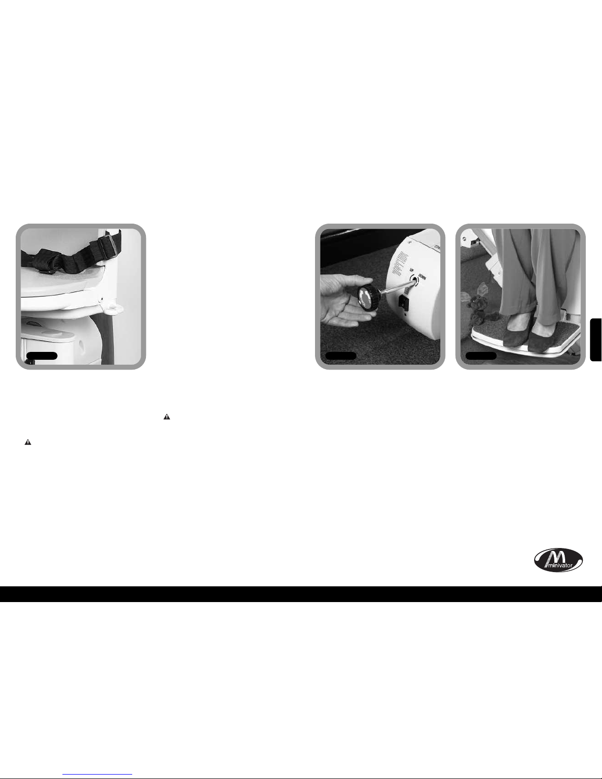
44
43
Fonctionnement
du pivot
Figure 10
Un siège pivotant est présent pour vous
permettre de monter/descendre du siège
plus facilement en haut des escaliers en
vous faisant pivoter sur le palier.
Pour faire fonctionner le siège
pivotant, attendez que le monteescaliers soit arrêté.
Pour faire pivoter le siège soit poussez
vers le bas le levier de pivotement (il y en a
un de chaque côté du siège) ou tirez le
vers le haut. Il relâchera les verrous du
siège et vous permettra de déplacer le
siège en poussant depuis le repose-pieds.
Lorsque le siège atteint 90 degrés il se
verrouillera en position de blocage.
Vous ne devrez pas essayer de quitter le
siège tant que le siège n’est pas
fermement fixé dans sa position de verrou.
Pour pivoter dans la direction opposée
suivez la même procédure, mais poussez
depuis le palier.
Fonctionnement du pivot électrique
(optionnel)
Si votre monte-escaliersa un pivot optionnel
électrique il n’y aura pas de levier inclus.
Pour faire pivoter le siège tirez vers le haut
l’interrupteur de fonctionnement. Lorsque
le monte-escaliers atteindra le haut des
escaliers continuez à tirer vers le haut
l’interrupteur de fonctionnement.
Le monte-escaliers émettra trois bip et puis
le siège pivotera. Lorsque le siège a
complètement pivoté de 90 degrés le siège
s’arrêtera.
Vousne devez pas essayer de quitter le siège
tant qu’il n’a pas tourné complètement.
Pour pivoter dans la direction opposée
suivez la même procédure à l’envers.
Poussez le levier de fonctionnement vers le
bas.Le siège émettra trois bip et puis après
une courte pause il tournera dans la
direction du trajet. Continuez de maintenir
le levier vers le bas. Le monte-escaliers va à
nouveau émettre trois bip avant de
commencer sa descente.
PRECAUTIONS DE SECURITE
NE JAMAIS
Faire pivoter le siège sans avoir attaché la
ceinture.
NE JAMAIS
Monter ou descendre du siège pivotant
tant qu’il n’est pas verrouillé.
NE JAMAIS
Essayer de faire fonctionner le siège
pivotant alors que le siège est en
mouvement. (Par sécurité, si vous essayez
cela, le monte-escaliers s’arrêtera).
NE JAMAIS
Essayer de monter ou descendre avec le
monte-escaliers alors que le siège n’est pas
en bonne position (exemple faire face
directement à la cage d’escaliers).
.
Dans le cas peu probable où le monteescaliers a une panne d’électricité totale
ou continue après le dernier rail il y a une
procédure de fonctionnement manuelle
d’urgence. S’il vous plaît suivez ces étapes:
1. Eteignez le monte-escaliers avec la clé.
2. Insérez la poignée de fonctionnement
manuel d’urgence (Figure 11).
3. Tournez la poignée dans la direction
indiquée pour le mouvement souhaité.
4. Lorsque la position souhaitée est
atteinte enlevez le remontoir manuel et
mettez en marche le monte-escaliers.
Si vous avez des doutes contactez votre
vendeur local Minivator ou appelez
directement le 08700 118282.
Votre monte-escaliers a des bords sécurisés
au dessous du repose-pieds et sur le monteescaliers lui-même qui arrêteront le monteescaliers si un objet venait à se piéger dans
le repose-pieds (Figure 12).
Pour enlever l’objet éloignez le
monte-escaliers de l’objet puis enlevez
l’objet de la cage d’escaliers. Enfin
procédez normalement pour utiliser votre
monte-escaliers.
Instructions de
fonctionnement manuel
en cas d’urgence
Objets piégés
Figure 11 Figure 12
Fonctionnement de votre Minivator Simplicity+950Fonctionnement de votre Minivator Simplicity+950
FRANCAIS
Page 24
46
45
xSécurité et entretienx
Nous conseillons d’entretenir votre monte-escaliers après les 12 premiers mois et après ça TOUS
LES 12 MOIS.
Cette tâche doit être faite pas une personne compétente, c’est à dire un vendeur approuvé par
Minivator.
Si il y un doute, s’il vous plait contactez le department de maintenance de Minivator au
08700 118282.
Si vous êtes proriétaire de votre monte-escaliers et que vous n’avez plus besoin de lui, votre
vendeur ou Minivator peut être intéressé par son rachat.
Mises en garde et précautions
NE JAMAIS
Permettre à plus d’une personne d’utiliser le monte-escaliers en meme temps.
La capacité maximale est de 120kg.
NE JAMAIS
Permettre à des enfants de jouer sur ou avec le monte-escaliers.
NE JAMAIS
Laisser rentrer de l’eau en contact avec les composants dans le monte-escaliers. Si vous
devez transporter des liquides FAITES TRÈS ATTENTION.
NE JAMAIS
Placez des objets sur le rail ou laisser des objets dans les escaliers, où ils pourraient rentrer
en contact avec le monte-escaliers durant son fonctionnement. Votre monte-escaliers est
équipé avec des bords sur les côté et dessous le plateau des pieds sensibles à la pression, qui
arrêteront automatiquement le monte-escaliers s’il détecte toute obstruction.
NE JAMAIS
Utilisez le monte-escaliers sans mettre la ceinture aux genoux, ou toutes autres ceintures de
sécurité ou de harnais.
NE JAMAIS
Utilisez le monte-escaliers en étant debout dessus.
TOUJOURS
Mettre vos PIEDS SUR LE PLATEAU DES PIEDS lorsque le monte-escaliers est en mouvement,
et essayer d’éviter de faire pendre vos pieds sur les bords du plateau des pieds.
NE JAMAIS
Pivoter le siège tant que le monte-escaliers n’est pas arrêté en haut ou en bas des escaliers.
TOUJOURS
Replier la chaise lorsque il n’est pas utilisé pour éviter d’encombrer le passage.
MISE EN GARDE
Si le contrôleur de dépassement de vitesse est activé il doit être réinitialisé par une
personne compétente, c’est à dire un vendeur approuvé par Minivator. Son activation est
indiquée quand le monte-escaliers ne peut pas descendre les escaliers et que l’affichage de
diagnostic affiche 0.
xSoin régulier et maintenancex
Entretien de la batterie
et chargement
V
otre monte-escaliers Minivator est alimenté
par batterie et continuera à fonctionner
pendant un certain temps même si vous avez
une coupure de courant. Vous pourrez
normalement monter et descendre les escaliers
au moins 10 fois sans avoir besoin de recharger
les batteries. En particulier lors d’une coupure
de courant, cependant vous devez toujours
vous assurer qu’il y a assez de lumière pour
permettre un déplacement sécurisé, et
spécialement à chaque extrémité du rail là où
vous mettez en marche et arrêter le monteescaliers.
Votre rail de monte-escaliers a des points de
charge, Normalement en haut et en bas de la
cage d’escaliers. Votre monte-escaliiers doit
être laissé sur un de ces points de chargement
lorsqu’il n’est pas utilisé pour s’assurer que les
batteries soient chargées. Si le monte-escaliers
émet un bip et/ou que l’affichage indique un
"2" lorsqu’il est laissé sur un point de charge et
qu’il n’est pas utilisé IL N’EST PAS EN CHARGE.
S’il vous plaît vérifiez que l’alimentation
électrique pour le monte-escaliers est sur
marche. Si elle est sur marche et que le bip
continue s’il vous plaît contactez votre vendeur
ou appelez le service client minivator au 08700
118282.
Maintenance
Il n’y pas de partie réparable par l’utilisateur
dans votre monte-escaliers. Si un dégât est
visible ou si votre monte-escaliers sonne ou a
un comportement inhabituel contactez
Minivator ou votre vendeur certifié
immédiatement. Nous conseillons de faire une
visite de maintenance de votre monte-escaliers
après les 12 premiers mois et après AU MOINS
TOUS LES 12 MOIS.
Soin et nettoyage
Avant le nettoyage de toute partie de votre
monte-escaliers Minivator s’il vous plaît assurez
vous d’avoir enlevé la clé.
Les monte-escaliers Minivator sont fabriqués
avec des matériaux différents, tous avec des
surfaces nettoyables facilement. Le siège et la
garniture peuvent être essuyés avec un chiffon
h
umidifié mais NON MOUILLÉ et avec une
p
etite quantité de liquide à vaisselle.
S’IL VOUS PLAIT N’UTILSEZ pas de nettoyant
abrasif, avec de la javel ou à base de solvant,
car cela endommagerait le siège.
Pour nettoyer le rail, en premier montez le
monte-escaliers en haut des escaliers.
Le rail peut être nettoyé avec un chiffon
humidifié.
Lorsque presque tout le rail est nettoyé, faites
descendre le monte-escaliers en bas des
escaliers et finissez de nettoyer le rail en vous
assurant qu’aucun débris de nettoyage ne soit
tombé dedans.
Pour maintenir votre monte-escaliers
Minivator en bon état mécanique, il est
recommandé de le faire maintenir par un
technicien qualifié.
Mise au rebut de
votre monte-escaliers
Votre monte-escaliers a été fabriqué en
utilisant des matériaux et composants de haute
qualité qui peuvent être recyclés et réutilisés.
Le symbole de poubelle barrée
d’une croix indique que votre
monte-escaliers est soumis à la
directive Européenne 2002/96/EC,
qui régit la mise au rebut de
déchet d’appareil électrique
et électronique.
Cela signifie que votre monte-escaliers ne doit
être pas être jeté avec les déchets domestiques
mais doit être mis au rebut de manière
appropriée pour recyclage.
Le recyclage de ce produit aidera à protéger
l’environnement en s’assurant que tous les
matériaux contenus dans le monte-escaliers
sont manipulés de façon adéquate.
S’il vous plaît contactez Minivator au 08700
118282, et votre vendeur ou votre bureau
municipal pour plus d’information concernant
sa mise à la poubelle.
FRANCAIS
Page 25
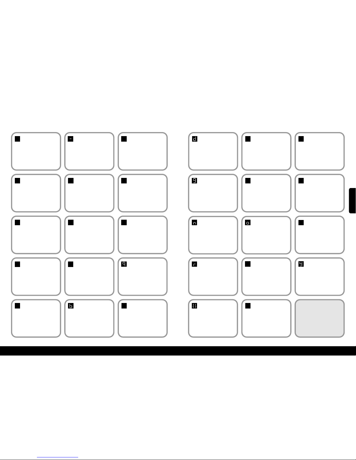
12
11
47
xAnnexe 1 – Affichage de Diagnosticx
Code:
Rien
Signification:
Pas d’affichage.
Faites vous-même:
Appuyez sur l’interrupteur et voyezsir
l’affichage se fait.Vérifiezque l’interrupteur
d’alimentationprincipale est sur marche.Si
celane résolve pas le problème,contactez
votrevendeurou Minivator.
Code:1Signification:
Nécessite le
chargement.
Faites vous-même:
Les batteries nécessitentun rechargement.
Amenez le monte-escaliers aux contacts
de charge– si le code ’Okay’ ne s’affiche
pas contactez votre vendeur ou Minivator.
Code:
Okay
Signification:
Okay.
F
aites vous-même:
Contactez votre vendeur ou Minivator.
Code:0Signification:
Limitefinale activée ou
court-circuitdu câble.
Faites vous-même:
Vérifiez que l’interrupteur à clé est sur
m
arche et que le siège est entièrement
pivoté vers la direction de trajet. Si cela
ne résolve pas le problème, contactez
votre vendeur ou Minivator.
0
1
Code:
4
Signification:
Bord de sécurité
(haut/bas) activé –
plateau des pieds.
Faites vous-même:
Contactez votre vendeur ou Minivator.
4
Code:
5
Signification:
Limite de fins activé.
Faites vous-même:
Contactez votre vendeur ou Minivator.
5
Code:7Signification:
Batteries ont un
niveau critique.
Faites vous-même:
Les batteries nécessite un chargement.
Amenez le aux contacts de charge Si le code 'Okay’ ne s’affiche pas
contactez votre vendeur ou Minivator.
7
Code:9Signification:
Affiché quand
l’interrupteur est
affiché sur direction
haut/bas.
Faites vous-même:
N/A.
Code:
6
Signification:
Bord de sécurité
(direction haut/bas
activé- plateau de
pieds).
Faites vous-même:
Contactez votre vendeur ou Minivator.
6
Code:2Signification:
Déchargé.
Faites vous-même:
Le monte-escaliers n’est pas stationné sur une
position de charge. Amenez le aux contacts de
charge –Si le code 'Okay’ ne s’affichepas ou si
le monte-escaliers est déjà sur les contacts
vérifiez que l’alim. est sur marchen.Sinon
contactez votre vendeur ou Minivator.
Code:3Signification:
Limite des fins
activée.
Faites vous-même:
Contactez votre vendeur ou Minivator.
2
3
Code:ASignification:
Articulation ouverte.
Faites vous-même:
Contactez votre vendeur ou Minivator.
Code:8Signification:
Affiché quand
l’interrupteur est
activé sur direction
haut/bas.
Faites vous-même:
N/A.
8
A
Code:bSignification:
Un interrupteur est actif
à alimen en marche cçd.
Interrupteurhaut, bas
Télécommande haut,
bas ou apprentissage.
Faites vous-même:
Contactez votre vendeur ou Minivator.
Code:CSignification:
L’infrarougeadresse
ne correspond pas.
Faites vous-même:
Contactez votre vendeur ou Minivator.
C
48
Code:dSignification:
Signification:
Relais de l’alim..
principale est soudé.
Faites vous-même:
Contactez votre vendeur ou Minivator.
Code:
E
Signification:
Alim..Principale le
relais ne ferme pas.
F
aites vous-même:
Contactez votre vendeur ou Minivator.
E
Code:FSignification:
Semi-conducteur de
frein échoué.
F
aites vous-même:
Contactez votre vendeur ou Minivator.
f
Code:gSignification:
Frein non connecté.
Faites vous-même:
Contactez votre vendeur ou Minivator.
Code:HSignification:
Relais d’alim.
principale has closed
early.
Faites vous-même:
Contactez votre vendeur ou Minivator.
H
Code:LSignification:
Limite courante
exceeded.
Faites vous-même:
Contactez votre vendeur ou Minivator.
l
Code:nSignification:
Demi Vitesse.
Faites vous-même:
Si affichage permanent contactez
votre vendeur ou Minivator.
Code:oSignification:
L
e tableau de
commande principal
a une mémoire
problème.
Faites vous-même:
Contactez votre vendeur ou Minivator.
Code:
P
Signification:
Le pivot électrique ne
répondpas.
Faites vous-même:
Contactez votre vendeur ou Minivator.
P
Code:rSignification:
Pas de charge
courante.
Faites vous-même:
Assurez vous que l’alim est sur
marche. Contactez votre vendeur ou
Minivator.
Code:
N/A
Signification:
Surcharge.
Faites vous-même:
Contactez votre vendeur ou Minivator.
Code:
N/A
Signification:
Le monte-escaliers est
en "mode sommeil"
pour préserver les
batteries.
Faites vous-même:
Appuyez sur le levier ou sur un bouton du
combiné pour réactiver le monte-escaliers.
Code:USignification:
Défaut d’alim.
Faites vous-même:
Contactez votre vendeur ou Minivator.
u
Code:YSignification:
Le tableau de
commande principal
a un logiciel échec.
Faites vous-même:
Contactez votre vendeur ou Minivator.
NOTEZ: Si l’affichage affiche
quelque chose mais codes de
diagnostic listés il nécessite
une réinitialisation.
Enlevez le monte-escaliers du
contact de charge. Eteignez
l’interrupteur principal pendant
10 secondes puis rallumez.
.8.
FRANCAIS
Page 26
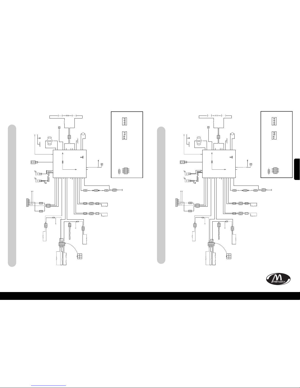
50
49
xAnnexe 2 – schemas de câblagex
Simplicity+ Schéma du bloc – monte-escaliers côté droit
xAnnexe 2 – schemas de câblagex
BORD DU BAS DU CHASSIS
PAN DE DESSOUS DU CHASSIS
BORDDU BAS DU
REPOSE-PIED
BORDDU HAUT DU REPOSE-PIED
BORDDE SECURITE DU PAN
CONNECTEUR DU
REPOSE-PIED AU CHASSIS
BORD DU HAUT DU CHASSIS
CONNECTEUR DU
SIEGE AU CHASSIS
AU CONNECTEUR DU SIEGE
VERS
L’EXTREMITE
FINALE
M
F
M
F
F
CONVERSION
LOOM
DEPASSEMENT
DU RAIL
CONTACT DE DONNEES
DE COMMUNICATION
D’ARTICULATION/
PLATEFORME
CONNEXION DU
PIVOT ELECTRIQUE
(UNIQUEMENT POUR OPTIONS ELECTRIQUES)
OSG
F
F
M
MFM
F
LIMITE DU BAS
DU RAIL
LIMITE DU HAUT
DU RAIL
AU
CONVERSION
LOOM
SW5
SW1
SW6
SW14
BLANC
BLANC
G
RIS
FICHE
FICHE
FICHE
FICHE RONDE
FICHE RONDE
CONNECTEUR
COSSE
OEILLET
CONNECTEUR A 9 VOIES CONNECTEUR A 8 VOIES
FICHE
BLANC
MARQUE
JAUNE
MARQUE
JAUNE
SW13
SW8
VIOLET
VUE DEPUIS LE
COTE DU CABLE
SW7
SW2
SW3
SW4
MARRON
MARRON
MARQUE
ROUGE
MARQUE
BLEU
MARQUE
BLEU
MARQUE
ROUGE
N
OIR
BLEU
SW10
SW9
ROUGE
ROUGE
ROUGE
MARRON
MARRON
VIOLET
VIOLET
VIOLET
VIOLET
VIOLET
VIOLET
ROUGE MARRON
GRIS
VIOLET
GRIS
BOUCLE VIOLETTE
GRIS
EPISSURE
DU CABLE
EPISSURE
DU CABLE
VOIR
CIRCUIT RH
VOIR
CIRCUIT RH
MARRONMARRON
ORANGE
VERT
BLEU
VERT
ORANGE
BLANC
BLANC
DIRECTION VERS LE BAS VERT
CONNECTEUR
A 3 VOIES
CONNECTEUR
A 3 VOIES
CONNECTEUR
A 3 VOIES
CAPTEURS
INFRAROUGE
LEVIER COMMUN BLEU
DIRECTION VERS LE HAUT ORANGE
BORD DE SECURITE DU HAUT DU CHASSIS MARRON
BORD DE SECURITE COMMUN GRIS
BORD DE SECURITE DU BAS DU CHASSIS VIOLET
LIMITE D’EXTREMITE DU BAS NOIR
LIMITE D’EXTREMITE DU BAS NOIR
LIMITE D’EXTREMITE DU HAUT BLEU
LIMITE D’EXTREMITE DU HAUT BLEU
LIMITE FINALE BLANC
1
1
12345
6
1
1 2 3
4 5 6
23456
221
1
1
1
2
3
1
1
1
2
3
4
5
6
7
8
1
11
2
3
2
+
5A
CABLEBLINDE
AFFICHAGE DE
DIAGNOSTIC
BK
+++
+
–
–––
–
BK
BATT
BATT
BATT
BATT
BATT
BATT
BATT
ROUGE
M2MOTEUR
M1MOTEUR
I
R-1
I
R-2
F
USIBLE
D
’ARTICULATION
D
ONNEES POURL’ARTICULATION
D
IAG
C
HARGE
CON-1
CON-1
CON-1
CON-2
CON-2
CON-2
CON-3
CON-3
CON-3
CON-3
CON-3
CON-3
CON-3
234567823456789
2
2
1
1
2
2
1
1
2
2
1
1
1
1
1
1 1 1 1 1
2
2
221
1
TENSION D’ENTREE
POSITIVE DE CHARGE
CHARGE NEGATIVE A
TRAVERS LE CHASSIS
MOTEUR
FREIN
FUSIBLE A
C
OMBUSTION
RAPIDE 15A
ALIMENTATION DE
PLATEAU DE PIED
ELECTRIQUE +24 VOLT
ISOLATION DE
LA BATTE RIE
DECONNEXION
DU PACK
BATTERIE
NOIR
NOIR
SW16
BLANC
NOIR
ROUGE
ROUGE
FICHE
BK2
B
K1
2
M+
M–
1 2
1
1
M F
CONNECTEUR A PRESSION
CLE:
= CONNECTEUR MULTI-BROCHES
TOUS LES CIRCUITS DE SECURITE
DOIVENT ÊTRE NORMALEMENT FERMES
FONCTION DES CAVALIERS
SUR LE PCB SMT
DIP 1
DEMI-VITESSE
V
ERS LE HAUT
DEMI-VITESSE
V
ERS LE BAS
P
ING DESACTIVEE
PLAT DESACTIVEE
ARTICULATION
D
ESACTIVEE
S
TANDARD
R
AMPE LENTE
INUTILSE
MARCHE
1
2 3 4
DIP 2
P
LEINE VITESSE
VERS LE HAUT
P
LEINE VITESSE
V
ERS LE BAS
PINGACTIVEE
PLAT ACTIVEE
A
RTICULATION
ACTIVEE
R
AMPE RAPIDE
I
NUTILSE
MARCHE
1
2 3 4
1 1
1
2
3
4
5
6
1
2
3
4
5
6
COMMUN
BORD DU BAS DU CHASSIS
PAN DE DESSOUS DU CHASSIS
CONNECTEUR DU
REPOSE-PIED AU CHASSIS
BORD DU HAUT DU CHASSIS
CONNECTEUR DU
SIEGE AU CHASSIS
AU CONNECTEUR DU SIEGE
VERS
L’EXTREMITE
FINALE
M
F
M
F
F
CONVERSION
LOOM
DEPASSEMENT
DU RAIL
CONTACT DE DONNEES
DE COMMUNICATION
D’ARTICULATION/
PLATEFORME
CONNEXION DU
PIVOT ELECTRIQUE
(UNIQUEMENT POUR OPTIONS ELECTRIQUES)
OSG
F
F
M
MFM
F
LIMITE DU BAS
DU RAIL
LIMITE DU HAUT
DU RAIL
AU
CONVERSION
LOOM
SW5
SW1
SW6
SW14
BLANC
B
LANC
GRIS
FICHE
FICHE
FICHE
FICHE RONDE
FICHE RONDE
CONNECTEUR
COSSE
OEILLET
C
ONNECTEUR A 9 VOIES CONNECTEUR A 8 VOIES
FICHE
BLANC
MARQUE
JAUNE
MARQUE
JAUNE
CSE1
SW13
SW8
VIOLET
VUE DEPUIS LE
COTE DU CABLE
SW7
SW2
SW3
SW4
MARRON
MARRON
MARQUE
ROUGE
MARQUE
BLEU
MARQUE
BLEU
MARQUE
ROUGE
NOIR
BLEU
SW10
SW9
ROUGE
ROUGE
ROUGE
MARRON
VIOLET
VIOLET
VIOLET
VIOLET
VIOLET MARRON
MARRON
ROUGE
MARRON MARRON
GRIS
VIOLET
GRIS
BOUCLE
MARRON
GRIS
EPISSURE
DU CABLE
EPISSURE
DU CABLE
VOIR
CIRCUIT LH
VOIR
CIRCUIT LH
MARRON
VIOLET
ORANGE
ORANGE
BLEU
VERT
VERT
BLANC
BLANC
DIRECTION VERS LE BAS VERT
CONNECTEUR
A 3 VOIES
CONNECTEUR
A 3 VOIES
CONNECTEUR
A 3 VOIES
CAPTEURS
INFRAROUGE
LEVIER COMMUN BLEU
DIRECTION VERS LE HAUT ORANGE
BORD DE SECURITE DU HAUT DU CHASSIS MARRON
BORD DE SECURITE COMMUN GRIS
BORD DE SECURITE DU BAS DU CHASSIS VIOLET
LIMITE D’EXTREMITE DU BAS NOIR
LIMITE D’EXTREMITE DU BAS NOIR
LIMITE D’EXTREMITE DU HAUT BLEU
LIMITE D’EXTREMITE DU HAUT BLEU
LIMITE FINALE BLANC
1
1
12345
6
1
1 2 3
4 5 6
23456
2
2
1
1
1
1
2
3
1
1
1
2
3
4
5
6
7
8
1
1
1
2
3
2
+
5A
CABLEBLINDE
AFFICHAGE DE
DIAGNOSTIC
BK
+++
+
–
–––
–
BK
BATT
BATT
BATT
BATT
BATT
BATT
BATT
R
OUGE
M2MOTEUR
M1MOTEUR
I
R-1
I
R-2
FUSIBLE
D
’ARTICULATION
DONNEES POURL’ARTICULATION
D
IAG
C
HARGE
CON-1
CON-1
CON-1
CON-2
CON-2
CON-2
CON-3
CON-3
CON-3
CON-3
CON-3
CON-3
CON-3
234567823456789
221
1
2
2
1
1
2
2
1
1
1
1
1 1 1 1 1 1
2
2
2
2
1
1
MOTEUR
FREIN
F
USIBLE A
C
OMBUSTION
R
APIDE 15A
ALIMENTATION DE
PLATEAU DE PIED
ELECTRIQUE +24 VOLT
ISOLATION DE
LA BATTE RIE
DECONNEXION
DU PACK
BATTERIE
NOIR
NOIR
SW16
BLANC
NOIR
ROUGE
ROUGE
FICHE
BK2
BK1
2
M+
M–
1 2
1
1
BORDDU HAUT DU
REPOSE-PIED
BORDDU BAS DU REPOSE-PIED
BORDDE SECURITE DU PAN
DEDESSOUS DU REPOSE-PIED
TENSION D’ENTREE
POSITIVE DE CHARGE
CHARGE NEGATIVE A
TRAVERS LE CHASSIS
M F
CONNECTEUR A PRESSION
CLE:
= CONNECTEUR MULTI-BROCHES
TOUS LES CIRCUITS DE SECURITE
DOIVENT ÊTRE NORMALEMENT FERMES
FONCTION DES CAVALIERS
SUR LE PCB SMT
1 1
1
2
3
4
5
6
1
2
3
4
5
6
COMMUN
DIP 1
D
EMI-VITESSE
V
ERS LE HAUT
D
EMI-VITESSE
V
ERS LE BAS
P
INGDESACTIVEE
PLAT DESACTIVEE
ARTICULATION
D
ESACTIVEE
S
TANDARD
R
AMPE LENTE
INUTILSE
MARCHE
1
2 3 4
DIP 2
P
LEINE VITESSE
V
ERS LE HAUT
PLEINE VITESSE
V
ERS LE BAS
P
ING ACTIVEE
P
LAT ACTIVEE
A
RTICULATION
A
CTIVEE
R
AMPE RAPIDE
I
NUTILSE
MARCHE
1
2 3 4
Simplicity+ Schéma du bloc – monte-escaliers côté gauche
FRANCAIS
Page 27
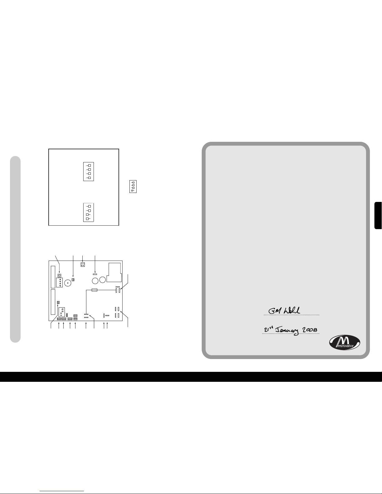
15
xAnnexe 2 – schemas de câblagex
52
51
BOUTON DE DETECTION
INFRAROUGE/RADIO
AUCUNE CONNEXION
NECESSAIRE
CONNECTEUR
DE FREIN
CHARGE +
POSITIF DE LA BATTERIE
NEGATIF DE LA BATTERIE
MOTEUR 1 (NOIR)
MOTEUR 2 (BLANC)
FUSIBLE 24VOLT
DONNEE D’ARTICULATION
(CABLE GRIS)
AUCUNE CONNEXION
NECESSAIRE
CAVALIER1
5A FUSIBLE GRILLANT
RAPIDEMENT
CAVALIER2
AUCUNE CONNEXION
NECESSAIRE
AUCUNE CONNEXION
NECESSAIRE
CONNECTEUR A 9 VOIES
ON
ON
1 2 3 4
1 2 3 4
CONNECTEUR A 8 VOIES
INFRAROUGE/RADIO
POUR TOUT CAVALIER CHANGE, S’IL VOUS PLAIT ETEIGNEZ LE
MONTE-ESCALIERS ATT ENDEZ 10 SECONDES, ET RALLUMEZ.
DIP 1
MARCHE
1
2 3 4
DIP 2
MARCHE
1
2 3 4
CLE
CAVALIERCSE126 MIS SUR MARCHE (TABLEAU DU PIVOT ELECTRIQUE)
CE PARAMETREVA ACTIVER LE MODE PIVOT ELECTRIQUE
MARCHE
1
2 3 4
DEMI-VITESSE VERS LE HAUT
V
ITESSE MOYENNE BAS
PING DESACTIVE
P
LAT DESACTIVE
ARTICULATION
D
ESACTIVEE
M
ONTE-ESCALIERS
COTE GAUCHE
RAMPE LENTE
INUTILISE
PLEINE VITESSE VERS LE HAUT
PLEINE VITESSE BAS
PLATACTIVE
PLATACTIVE
ARTICULATION
A
CTIVEE
M
ONTE-ESCALIERS
C
OTE DROIT
R
AMPE RAPIDE
INUTILISE
xAnnexe 3 – Certificat de conformitéx
Nous
Minivator Ltd
de
82 First Avenue
Pensnett Estate
Kingswinford
West Midlands
DY6 7FJ, England.
Déclarons de notre unique responsabilité que le produit
Minivator Simplicity+ 950 Monte-escaliers
a été fabriqué en conformité avec les standards
et spécifications suivants:
BS5776:1996 Powered Stairlifts
ISO 9386-2 2000-11-01
Ce à quoi cette déclaration est en conformité avec les standards
nationaux suivants:
Directive sur la compatibilité électromagnétique 89/336/EEC
Directive sur la basse tension – 73/23/EEC
Directive sur les machines – 98/37/EEC
Signé:
Nom: G. Welch
Date:
Poste: Directeur de l’ingénierie
Simplicity+ côté gauche et droit standard/pivot automatique
FRANCAIS
Page 28
53
Informations importantes au sujet de votre monte-escaliers
qui doivent être remplies par le technicien d’installation.
Installé par (Nom de la société)
N° de série
Date d’installation
Premier service due
Tampon du vendeur
54
FRANCAIS
Page 29
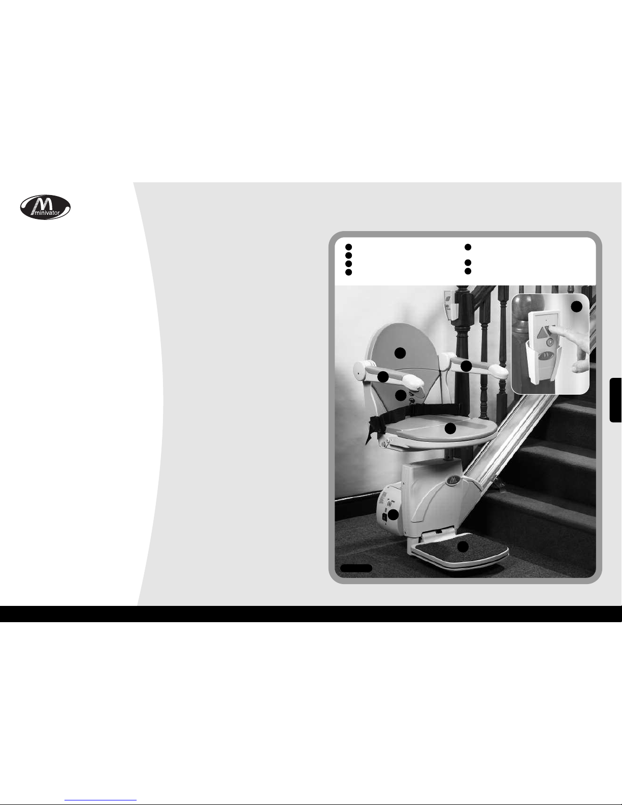
Gracias por elegir un subescaleras
Minivator. Por favor, lea estas
instrucciones de funcionamiento con
cuidado. Su subescaleras Minivator ha
sido diseñado y construido prestando
mucha atención a los detalles. Para tener
varios años de uso sin problemas, por
favor siga las instrucciones, prestando
especial atención a los requerimientos de
cuidado y mantenimiento. Minivator
recomienda que no realice tareas de
mantenimiento, con excepción de un
cuidad y limpieza rutinarios, los que se
explican en este manual.
Por favor contacte a su representante de
Minivator o a nuestro Departamento de
Servicio al Cliente en el Reino Unido, al
teléfono: 08700 118282 si su subescaleras
requiere atención; le ayudaremos con gusto.
Estándares Británicos
Minivator ha sido acreditado en
conformidad con el estándar internacional
de manufactura, reconocido con el premio
ISO 9001.
Todos los subescaleras Minivator han sido
diseñados y probados para cumplir con el
Estándar Británico de subescaleras
(BS5776):1996 así como ISO 9386-2.
También llevan la marca CE.
Los Minivator reciben regularmente
una auditoría para garantizar que
siempre cumplimos con ISO 9001 y
esto le brinda a usted la seguridad de
que usamos un producto de alta
calidad y bien fabricado.
Introducción 55
Estándares Británicos 55
Características de su 56
Minivator Simplicity
+ 950
Operando su 57
Minivator Simplicity
+ 950
Interruptor con llave
57
Interruptor on/off (encendido/apagado)
57
Pantalla de diagnóstico 58
Antes de su uso 58
Palanca de operación 59
Control Remoto 59
Plegando su subescaleras 60
Operando la opción giratoria 61
Instrucciones de giro de
emergencia manual 62
Artículos atrapados 62
Seguridad y mantenimiento 63
Advertencias y precauciones 63
Cuidado y limpieza
rutinarios 64
Cuidado y carga de la batería 64
Cuidado y limpieza 64
Eliminación de su subescaleras 64
Anexo 1 65
– Muestra del diagnóstico
Anexo 2 67
–
Diagramas de cableado
Anexo 3 70
– Certificado de conformidad
55
Introducción
56
Página
1
2
3
4
6
6
7
Figura 1
Características de su Minivator Simplicity+950
Asiento plegable
Asiento giratorio
Control remoto infrarrojo
Reposapiés plegable con bordes
de seguridad
Control del interruptor principal fácil
de operar
Apoyabrazos plegables
Muestra de diagnóstico
1
2
3
4
5
6
7
5
ESPAÑOL
Page 30
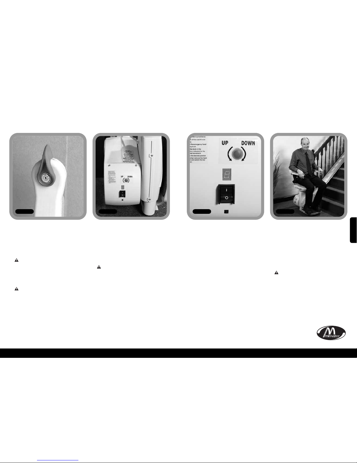
Operando su Minivator Simplicity+ 950
Operando su Minivator Simplicity
+ 950
Su subescaleras Minivator viene equipado
con un interruptor principal (Figura 2).
El subescaleras no puede operarse a menos
que la llave del interruptor se coloque en
posición de “on” (encendido).
La llave del interruptor se le
proporciona para permitirle bloquear
el subescaleras y evitar que sea usado
por otros (por ejemplo, niños).
Sin embargo, puede dejarse en la posición
de “on” (encendido) si se desea.
Si retira la llave por motivos de
seguridad, por favor asegúrese de
ponerla en un lugar seguro.
Si el interruptor se deja en posición de
“off” (apagado), el elevador continuará
cargándose.
Así como el interruptor con llave, su
subescaleras viene equipado con un
interruptor de on/off (encendido/apagado)
(Figura 3) en el panel inferior lateral del
elevador.
Asegúrese que este se encuentre en
posición de ‘ON’. El panel de
visualización de diagnóstico de fallas se
iluminará para indicar esto
.
Si piensa estar lejos de casa por un largo
período de tiempo, y decide apagar la
alimentación principal, es importante que
también apague elevador desde este
interruptor de on/off.
Esto asegurará que las baterías del
elevador permanezcan cargadas mientras
está fuera.
Antes de su uso
Antes de usar su subescaleras, LO MÁS
IMPORTANTE es que debe asegurarse que
en las escaleras no haya personas, mascotas
u otros objetos que podrían obstaculizar a
su subescaleras.
Luego asegúrese que los brazos, reposapiés
y asiento estén plegados hacia abajo para
garantizar su seguridad (Figura 5).
ANTES DE OPERAR SU
SUBESCALERAS SIEMPRE AJUSTE
LA CORREA DE SU REGAZO.
58
Interruptor con Llave
Interruptor
encendido/apagado
57
Figura 2 Figura 3 Figura 4 Figura 5
Pantalla de diagnóstico
El subescaleras viene equipado con una
pantalla de diagnóstico (Figura 4) que
muestra un código para ayudar a
diagnosticar fallas. Revise el Anexo 1 para
tener una explicación de los códigos de
diagnóstico. Si experimenta un problema
con su elevador, examine la pantalla y
escriba una nota de los códigos en pantalla.
Por favor, informe al operador de servicio al
cliente acerca de estos códigos cuando
notifique la falla.
ESPAÑOL
Page 31
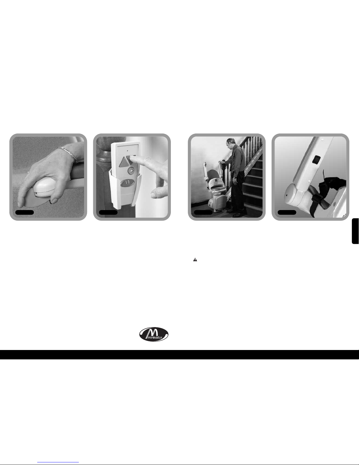
60
59
Operando su Minivator Simplicity+ 950
Operando su Minivator Simplicity
+ 950
Palanca de operación
Figura 6
El control remoto (Figura 7) se usa ya sea
para llamar al elevador ya sea a la parte
superior o a la parte inferior de la escalera,
o para acomodar una bisagra eléctrica
plegada en su lugar. Este control también
puede usarlo un asistente cuando el
usuario no puede operar el subescaleras
por sí mismo.
El asistente siempre debe permanecer
fuera de las escaleras hasta que el
subescaleras se haya detenido.
El asiento, apoyabrazos y reposapiés de su
Minivator Simplicity+ 950 pueden plegarse
para permitir subir y bajar las escaleras de
manera más fácil cuando éste no está en
uso (Figura 8).
PRECAUCIÓN DE SEGURIDAD!
SIEMPRE REGRESE EL SUBESCALERAS A LA
POSICIÓN DONDE LO ACOSTUMBRA
GUARDAR. ES DECIR, CON LOS
APOYABRAZOS, ASIENTO Y REPOSAPIÉS
PLEGADOS Y LA SILLA PARALELA AL RIEL
COMO SE OBSERVA EN LA FIGURA 9, PARA
NO OBSTACULIZAR LAS SALIDAS.
Unión de reposapiés manual
(opcional)
Si su subescaleras viene equipado con una
unión de reposapiés manual, el reposapiés
se plegará automáticamente cuando el
cojín del asiento delantero se levante.
Asimismo, bajará el reposapiés cuando el
cojín del asiento delantero se baje.
Unión de reposapiéseléctrico– operado
desde el cojín del asiento (opcional)
Si su subescaleras viene equipado con una
unión de reposapiés eléctrico que puede
operarse desde el cojín del asiento, plegará
automáticamente el reposapiés cuando se
levante el cojín del asiento delantero.
También bajará el reposapiés cuando el
cojín del asiento delantero se baje.
Unión de reposapiés eléctrico –
operado desde el brazo (opcional)
Si su subescaleras viene equipado con una
unión de reposapiés eléctrico que puede
operarse desde el brazo, tendrá un
interruptor adicional bajo el brazo (Figura
9). Para bajar el reposapiés, use el
interruptor oscilador bajo el brazo. Para
levantar el reposapiés, mueva el interruptor
oscilador a su posición alternativa.
Nota: Si está moviendo el reposapiés
mientras está sentado en el subescaleras,
por favor asegúreseque sus pies no estén
obstaculizando el reposapiés cuando esté en
movimiento.
Control remoto
Plegando su subescaleras
Figura 7 Figura 8
Su subescaleras Minivator funciona
simplemente presionando y moviendo la
palanca de operación en la dirección donde
desea viajar (Figura 6). El subescaleras se
detendrá automáticamente cuando suelte
la palanca o cuando éste haya alcanzado el
fin de su trayectoria.
POR FAVOR NOTE LO SIGUIENTE:
Por motivos de seguridad, la activación
inicial del subescaleras tiene 1 segundo de
retraso desde que presiona y mueve la
palanca de operación, para evitar una
operación accidental. Si suelta la palanca
mientras que el elevador está en
movimiento, éste se detendrá y habrá un
retraso de 1 segundo antes que la palanca
vuelva a iniciar el elevador.
Al cambiar la dirección de la trayectoria, el
retraso será de 3 segundos antes que el
elevador empiece a moverse.
Figura 9
ESPAÑOL
Page 32
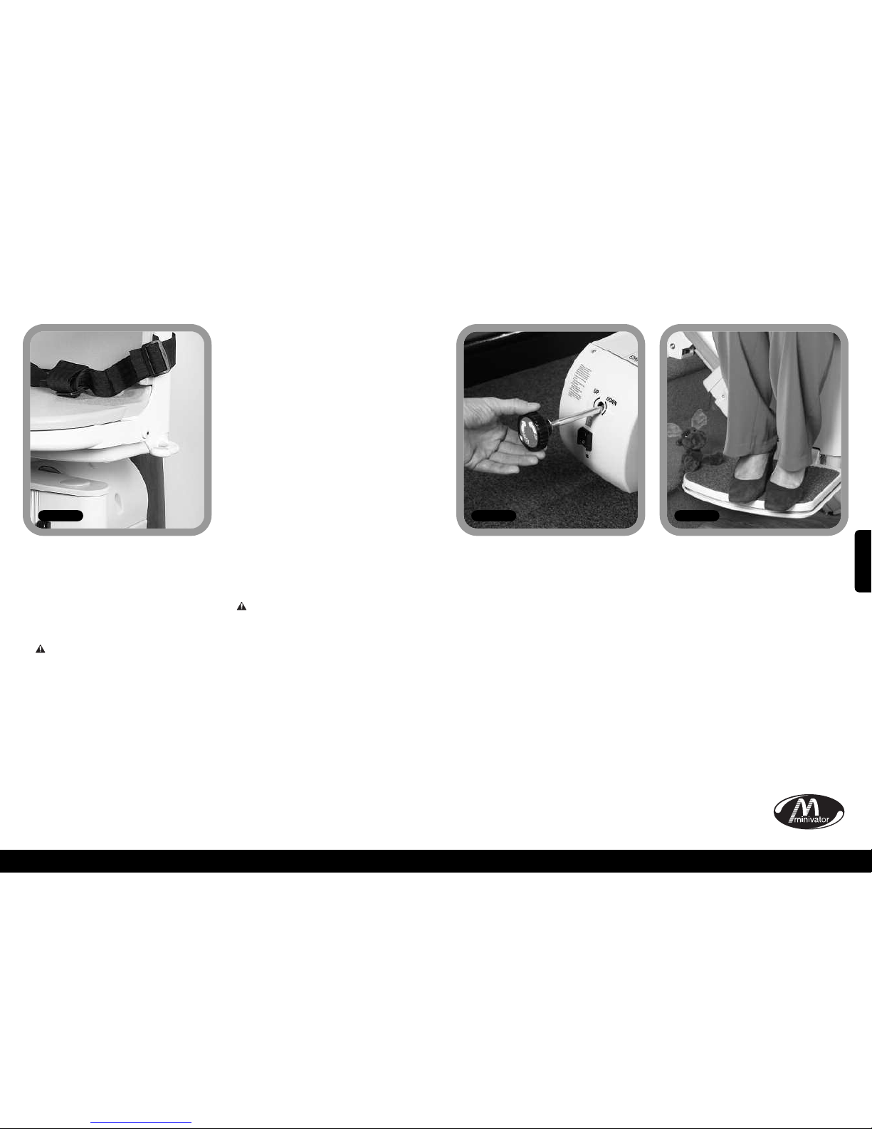
62
61
Operando su Minivator Simplicity+ 950
Operando la opción
giratoria
Figura 10
Se incluye un asiento giratorio para
permitirle subirse/bajarse del asiento más
fácilmente en la parte superior de las
escaleras, girando hacia el lado por donde
va a bajar.
Para operar el asiento giratorio, espere
hasta que el subescaleras se haya
detenido.
Para girar el asiento coja ambas palancas
giratorias hacia abajo o jálelas hacia arriba
(hay una a cada lado del asiento). Esto
soltará el bloqueo del asiento y le permitirá
girar el asiento empujándolo lejos del
reposapiés. Cuando el asiento alcance los
90 grados, se bloqueará en su posición.
No debe intentar salir del asiento hasta
que se haya fijado (haciendo “clic”) en su
posición de bloqueo.
Para girar en la dirección opuesta, siga el
mismo procedimiento, pero empújese lejos
del lado por donde va a bajar.
Opción giratoria eléctrica (opcional)
Si su subescaleras viene equipado con una
opción giratoria eléctrica, no habrá
palancas giratorias. Para girar el asiento
coloque la palanca de operación en
dirección hacia arriba. Cuando el
subescaleras alcance la parte superior de
las escaleras continúe sosteniendola palanca
de operación en dirección hacia arriba.
El subescaleras dará tres pitidos y luego el
asiento girará. Cuando el asiento haya
girado completamente a 90 grados, el
asiento se detendrá.
No deberá intentar bajar del asiento hasta
que éste haya girado por completo.
Para girar en la dirección opuesta, siga el
mismo procedimiento pero a la inversa.
Presione la palanca de operación en
dirección hacia abajo. El asiento dará tres
pitidos y luego de una corta pausa
empezará a rotar a la dirección deseado.
Continúe sosteniendo la palanca de
operación en dirección hacia abajo. El
subescaleras volverá a dar tres pitidos antes
de descender.
PRECAUCIONES DE SEGURIDAD
NUNCA
Gire el asiento sin haberse ajustado la
correa en el regazo.
NUNCA
Se suba o baje del asiento giratorio a
menos que esté en posición de bloqueo.
NUNCA
Intente operar el asiento giratorio con el
subescaleras en movimiento. (Como
precaución de seguridad, si intenta usarlo
con el elevador en movimiento, éste se
detendrá).
NUNCA
Intente subir o bajar las escaleras a menos
que el asiento esté en posición correcta (es
decir, directamente frente a las escaleras).
Operando su Minivator Simplicity+ 950
En el caso poco probable que el elevador
sufra una falla eléctrica total o que no
consiga llegar a la parada del riel final,
entonces se procederá a un giro de
emergencia manual. Por favor, siga estos
pasos:
1. Apague el interruptor del subescaleras
con la llave.
2. Inserte la perilla de giro de emergencia
manual (Figura 11).
3. Gire la perilla en la dirección indicada
para el movimiento requerido.
4. Cuando logre la posición deseada, retire
la perilla manual y encienda el elevador.
Si tiene dudas, contacte a su representante
aprobado de Minivator local o llámelo
directamente por teléfono al 08700 118282.
Su subescaleras viene equipado con bordes
de seguridad en la parte inferior del
reposapiés y en el elevador mismo, el cual
detendrá el subescaleras si algún artículo se
quedara atrapado en el reposapiés
(Figura 12).
Para retirar el artículo, invierta el
movimiento del subescaleras lejos del
objeto y retire el objeto de las escaleras.
Continúe utilizando su subescaleras como
siempre.
Instrucciones de giro
de emergencia manual
Artículos atrapados
Figura 11 Figura 12
ESPAÑOL
Page 33

64
63
xSeguridad y mantenimientox
Le aconsejamos realizar el mantenimiento de su subescaleras luego de los primeros 12 meses de
uso y posteriormente, AL MENOS CADA 12 MESES.
Esta tarea debe hacerla una persona competente, es decir un representante aprobado por
Minivator.
Si está en duda, por favor contacte al Departamento de Mantenimiento de Minivator el teléfono
08700 118282.
Si el subescaleras es de su propiedad y ya no necesita utilizarlo, su representante o Minivator
podrían estar interesados en adquirirlo.
Advertencias y precauciones
NUNCA
Permita que más de una persona utilice el subescaleras a la vez.
La capacidad máxima de carga es 120kg.
NUNCA
Permita que los niños jueguen encima o con el subescaleras.
NUNCA
Permita que el agua entre en contacto con los componentes del subescaleras. Si tiene que
transportar líquidos, HÁGALO CON CUIDADO.
NUNCA
Coloque objetos en el riel ni los deje en las escaleras, donde podrían entrar en contacto con
el elevador en movimiento. Su subescaleras viene equipado con bordes laterales sensibles a
la presión y una bandeja inferior en el reposapiés que detendrá automáticamente el
elevador si detecta cualquier obstáculo.
NUNCA
Use el subescaleras sin la correa en el regazo, u otro cinturón de seguridad o arnés.
NUNCA
Use el subescaleras cuando esté de pie.
SIEMPRE
Mantenga sus PIES EN EL REPOSAPIÉS hasta que el subescaleras siga en movimiento, e
intente evitar que sus pies cuelguen de los bordes del reposapiés.
NUNCA
Gire el asiento hasta que el elevador se haya detenido en la parte superior o inferior del
subescaleras.
SIEMPRE
Pliegue la silla cuando no esté en uso para evitar obstaculizar las salidas.
ADVERTENCIA
Si se activa el regulador de sobrevelocidad, debe apagarlo solamente una persona
competente, es decir un representante aprobado por Minivator. La activación del regulador
de sobrevelocidad se indica cuando el elevador no puede impulsarse hacia abajo de las
escaleras y la pantalla de diagnóstico muestra un 0.
xCuidado y mantenimiento rutinariosx
Cuidado y carga de
la batería
Su subescaleras Minivator funciona con
baterías y continuará funcionando por un
período de tiempo incluso si tiene un corte de
energía. Normalmente, debería poder ir hacia
arriba y abajo en las escaleras 10 veces sin
tener que cambiar las baterías. Especialmente
en caso de corte de energía; sin embargo,
siempre debe asegurarse que haya suficiente
luz para tener un ascenso o descenso seguro y
más específicamente en cada extremo del riel
donde se suba y baje del elevador.
El riel de su subescaleras viene equipado con
puntos de carga, normalmente en la parte
superior e inferior de las escaleras. Su
subescaleras debe permanecer en uno de esos
puntos de carga cuando no esté en uso para
asegurarse que las baterías se carguen. Si el
subescaleras emite un pitido y/o la pantalla
muestra un “2” cuando se deja en un punto
de carga y no está en uso, entonces NO SE
ESTÁ CARGANDO. Por favor, revise que la
alimentación de corriente del subescaleras esté
encendida. Si está encendida y sigue dando
pitidos, por favor contacte a su representante
o al Departamento de Mantenimiento de
Minivator al teléfono 08700 118282.
Mantenimiento
No hay partes que puedan ser reparadas por el
usuario en su subescaleras. Si aparece un daño
visible o su subescaleras suena o se comporta
de manera extraña, contacte a Minivator o a
su representante aprobado inmediatamente.
Recomendamos realizar el mantenimiento de
su subescaleras luego de los primeros 12 meses
de uso y posteriormente, AL MENOS CADA 12
MESES.
Cuidado y limpieza
Antes de limpiar cualquier parte de su
subescaleras Minivator, por favor asegúrese de
haber retirado la llave.
El subescaleras de Minivator ha sido diseñado
con una variedad de materiales, todos con
superficies “de fácil limpieza”. Las cubiertas
del asiento y cuerpo pueden limpiarse con un
paño húmedo, NO MOJADO, y una pequeña
cantidad de detergente líquido.
POR FAVOR, NO use limpiadores abrasivos,
lejía o limpiadores en base a solventes, ya que
estos dañarán el asiento.
Para limpiar el riel, primero envíe el
subescaleras a la parte superior de las
escaleras. El riel puede limpiarse con un paño
húmedo. Cuando la mayor parte del riel esté
limpia, lleve el subescaleras a la parte inferior
de las escaleras y termine de limpiar el riel,
asegurándose que ningún resto de limpieza
caiga sobre él.
Para conservar su subescaleras Minivator en
buenas condiciones mecánicas, se recomienda
llevar a cabo mantenimientos regulares por
parte de ingenieros de mantenimiento
calificados.
Eliminación de su
Subescaleras
Su subescaleras ha sido fabricado con
materiales y componentes de alta calidad, que
pueden reciclarse y reutilizarse.
El símbolo de basurero con ruedas
tachado con una cruz indica que su
subescaleras cumple con la
Directiva Europea 2002/96/EC, la
cual rige sobre la eliminación de
equipos eléctricos y electrónicos de desecho.
Esto significa que su subescaleras no debe
eliminarse como basura del hogar, sino que
debe eliminarse adecuadamente o dejarse en
un lugar de reciclaje.
El reciclaje de este producto ayudará a
proteger el medio ambiente, asegurando que
todos los materiales del subescaleras se
manejen adecuadamente.
Por favor, contacte a Minivator al teléfono
08700 118282, su representante o municipio
local para mayor información sobre
eliminación de este tipo de artefactos.
ESPAÑOL
Page 34
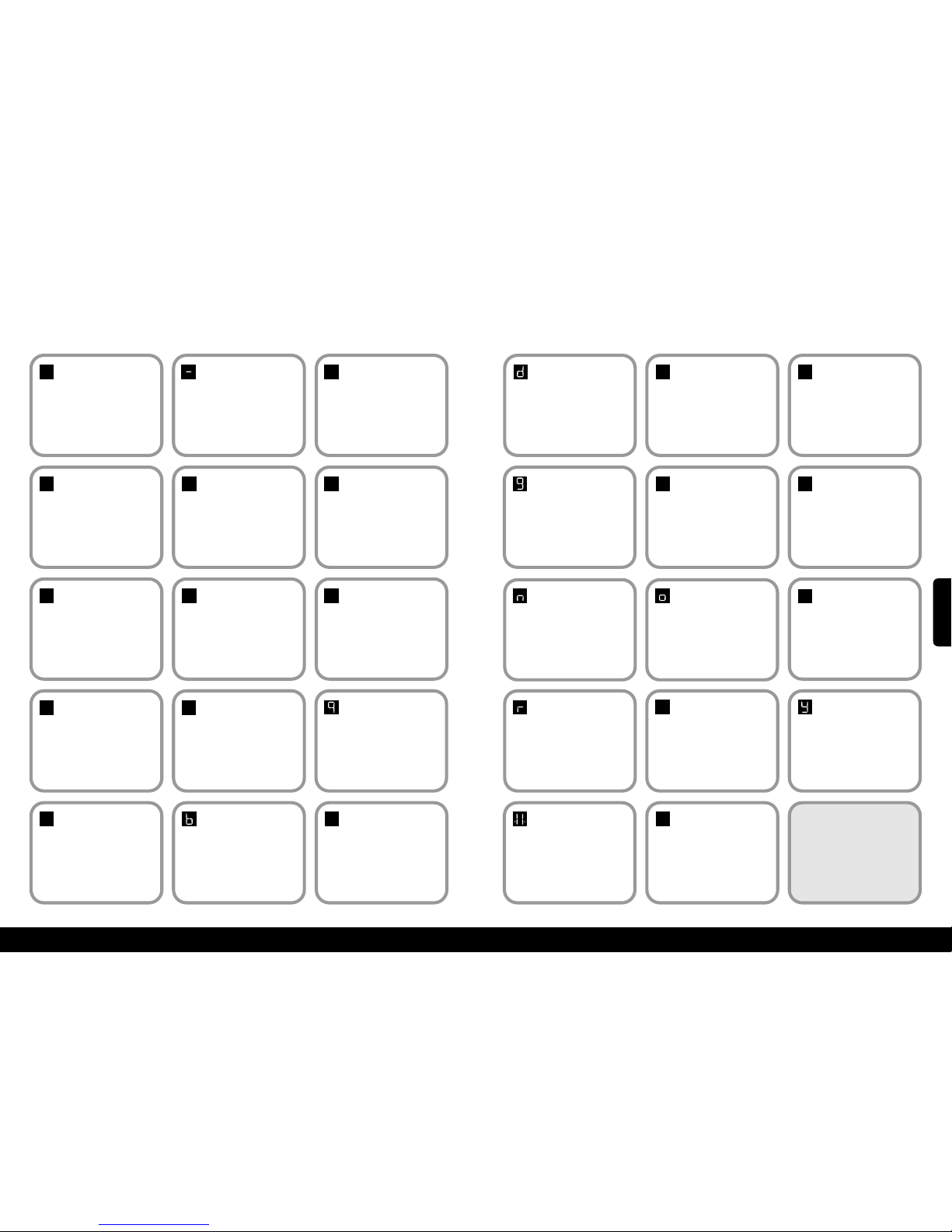
12
11
65
xAnexo 1 – Pantalla de diagnósticox
Signif:
Ninguno
Código:
No muestra.
Acción de auto ayuda:
Presioneel interruptorde palancay vea si
la pantalla se enciende. Verifiqueque el
interruptor de corrienteprincipalen el
elevador esté encendido. Si esto no arregla la
falla contactea su distribuidor o a Minivator.
Signif:1Código:
Se requiere carga.
Acción de auto ayuda:
Las baterías de su silla elevadora
requieren de carga. Lleve el elevador a
los contactos de carga –
Si el código de 'Ok’ no se muestra
contacte a su distribuidor o a Minivator.
Signif:OkCódigo:
Ok.
A
cción de auto ayuda:
Contacte a su distribuidor o a
Minivator.
Signif:0Código:
Límite final activado O
corto circuito de cable.
Acción de auto ayuda:
Verifiqueque la el interruptor de llave
esté encendido y que el asiento esté
totalmenteoscilado a la posición de
control.Si esto no arregla la falla contacte
a su distribuidoro a Minivator.
0
1
Signif:
4
Código:
Borde de seguridad
(dirección
arriba/abajo) activado
Lámina de pie.
Acción de auto ayuda:
Contacte a su distribuidor o a
Minivator.
4
Signif:
5
Código:
Límites de extremos
activados.
Acción de auto ayuda:
Contacte a su distribuidor o a
Minivator.
5
Signif:7Código:
Baterías acercándose a
nivel crítico.
Acción de auto ayuda:
La silla elevadora requiere de carga. Lleve
el elevador a los contactos de carga, si el
código de 'Ok’ no se muestra contacte a su
distribuidoro a Minivator.
7
Signif:9Código:
Muestra cuando el
interruptor de la
palanca está
activado en dirección
arriba/abajo.
Acción de auto ayuda:
N/A.
Signif:
6
Código:
Borde de seguridad
(plataforma-activada
en la dirreción
arriba/abajo).
Acción de auto ayuda:
Contacte a su distribuidor o a Minivator
6
Signif:2Código:
Sin carga.
Acción de auto ayuda:
La silla elevadora no está estacionada en el punto
de cargao no está cargando. Llévelaa los contactos
de carga – Si el código 'Ok’ no se muestra o si el
elevador ya está en los contactos de carga verifique
si la fuente de poder está encendida.Si esto falla
contacte a su distribuidor o a Minivator
Signif:3Código:
Límites de extremos
activados.
Acción de auto ayuda:
Contacte a su distribuidor o a
Minivator.
2
3
Signif:ACódigo:
Bisagra abierta.
Acción de auto ayuda:
Contacte a su distribuidor o a
Minivator.
Signif:8Código:
Muestra cuando el
interruptor de la
palanca está
activado en dirección
arriba/abajo.
Acción de auto ayuda:
N/A.
8
A
Signif:bCódigo:
Interruptor A está
activado en por ejemplo.
Palanca Arriba, Palanca
Abajo, IR Arriba, IR
Abajo o Aprendizaje.
Acción de auto ayuda:
Contacte a su distribuidor o a Minivator.
Signif:CCódigo:
Dirección IR
La dirección IR
(interruptor de
inclinación) no
coincide.
Acción de auto ayuda:
Contacte a su distribuidor o a Minivator.
C
66
Signif:dCódigo:
El interruptor de
corriente principal
está cercanamente
soldado.
Acción de auto ayuda:
Contacte a su distribuidor o a
Minivator.
Signif:
E
Código:
El interruptor de
corriente principal no
se cerró.
Acción de auto ayuda:
Contacte a su distribuidor o a
Minivator.
E
Signif:FCódigo:
Semi-conductor
de corte falló.
A
cción de auto ayuda:
Contacte a su distribuidor o a
Minivator.
f
Signif:gCódigo:
Freno no conectado.
Acción de auto ayuda:
Contacte a su distribuidor o a
Minivator.
Signif:HCódigo:
El interruptor de
corriente principal Se
cerró anticipadamente.
Acción de auto ayuda:
Contacte a su distribuidor o a
Minivator.
H
Signif:LCódigo:
Límite actual
excedido.
Acción de auto ayuda:
Contacte a su distribuidor o a
Minivator.
l
Signif:nCódigo:
Velocidad media.
Acción de auto ayuda:
Si se muestra permanentemente.
Contacte a su distribuidor o a
Minivator.
Signif:oCódigo:
El tablero de control
principal tiene un
problema de memoria.
Acción de auto ayuda:
Contacte a su distribuidor o a
Minivator.
Signif:
P
Código:
Eléctricono
respondió.
Acción de auto ayuda:
Contacte a su distribuidor o a
Minivator.
P
Signif:rCódigo:
No hay corriente de
carga.
Acción de auto ayuda:
Asegúrese de que la fuente de poder
esté conectada. Si lo está Contacte a
su distribuidor o a Minivator.
Signif:
N/A
Código:
Sobrecarga.
Acción de auto ayuda:
Contacte a su distribuidor o a
Minivator.
Signif:
N/A
Código:
El elevador está en el
“modo durmiente”
para conservar la
energía de la batería.
Acción de auto ayuda:
Oprima el botón del conmutador o del
mando a distancia para “despertar” al
elevado.
Signif:UCódigo:
Fuente de poder con
fallos.
Acción de auto ayuda:
Contacte a su distribuidor o a
Minivator.
u
Signif:YCódigo:
El tablero de control
principal tiene una
falla de software.
Acción de auto ayuda:
Contacte a su distribuidor o a
Minivator.
NOTA: SI LA PANTALLA NO
MUESTRA MÁS QUE LOS CÓDIGOS
DE DIAGNÓSTICO LISTADOS
REQUIERE UN REINICIO
Apague el interruptor principal de
la unidad por 10 segundos y luego
enciéndalo nuevamente. Quite el
elevador de los contactos de carga.
.8.
ESPAÑOL
Page 35
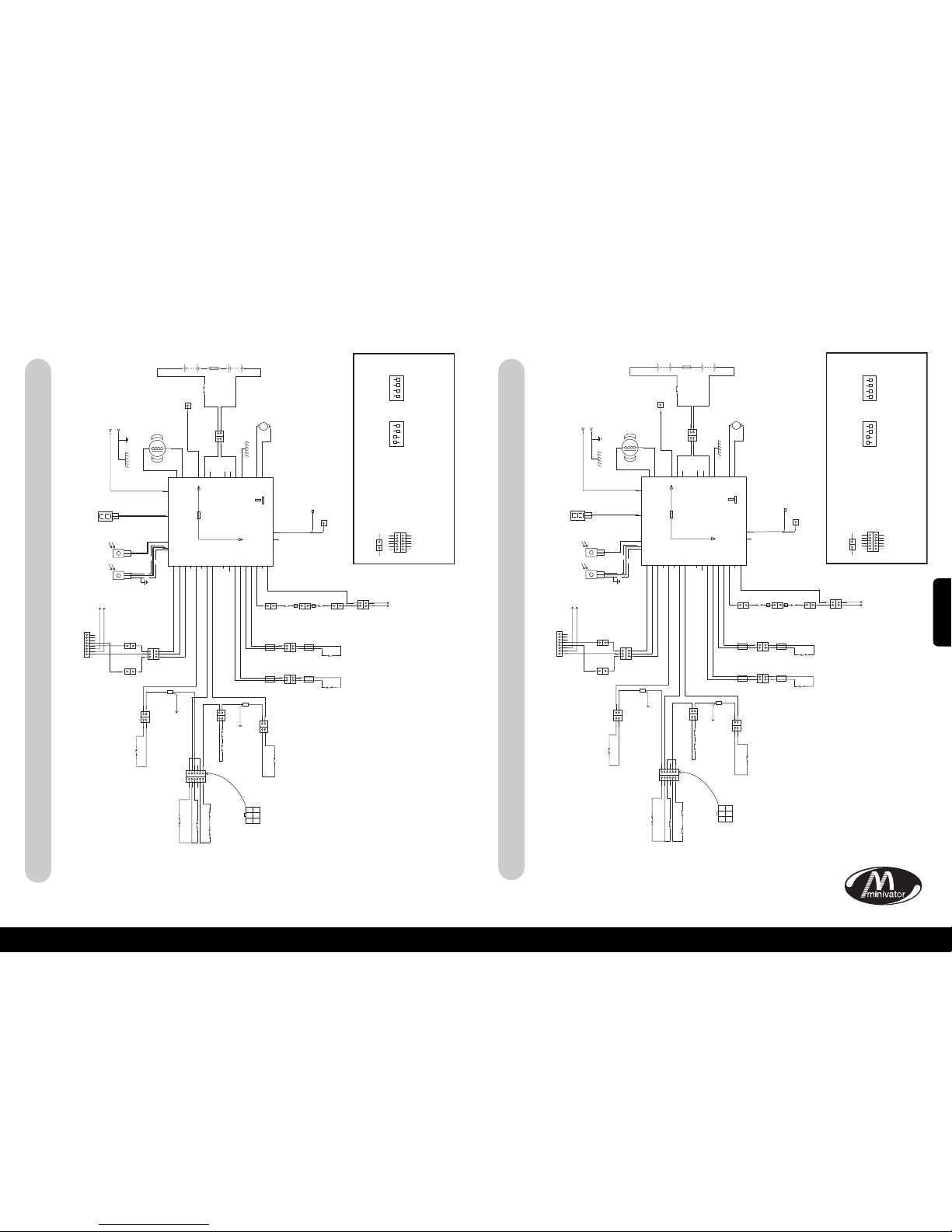
68
67
xAnexo 2 – Diagramas de cableadox
Simplicity+ Bloque Esquemático – Subescaleras de la Mano Derecha
xAnexo 2 – Diagramas de cableadox
Simplicity+ Bloque Esquemático – Subescaleras de la Mano Izquierda
BORDE INFERIOR DEL CHASIS
RESGUARDO INFERIOR
DEL CHASIS
BORDEINFERIOR DEL
REPOSAPIÉS
BORDESUPERIOR DEL REPOSAPIÉS
REPOSAPIÉSBAJO EL BORDE DE
RESGUARDODE SEGURIDAD
CONECTOR DE LA
PLATAFORMAAL CHASIS
BORDE SUPERIOR DEL CHASIS
CONECTOR DEL
ASIENTO AL CHASIS
SUJECIÓN AL ASIENTO
AL
EXTREMO
FINAL
M
F
M
F
F
CUADRO DE
CONVERSIÓN
DESCARRILADO
CONTACTO DE
COMUNICACIÓN
DE DATOS
PLATAFORMA/
COLECTOR
CONEXIÓN DEL
GIRO ELÉCTRICO
(SOLAMENTE OPCIONES DE ENERGÍA)
OSG
F
F
M
MFM
F
LÍMITE INFERIOR
DEL RAIL
LÍMITE SUPERIOR
DEL RAIL
AL
CUADRO DE
CONVERSIÓN
SW5
SW1
SW6
SW14
BLANCO
BLANCO
G
RIS
ESPADA
ESPADA
ESPADA
BALA
BALA
CONECTOR
DEL
TERMINAL
EN ANILLO
CONECTOR DE 9 VÍAS CONECTOR DE 8 VÍAS
ESPADA
BLANCO
ETIQUETA
AMARILLA
ETIQUETA
AMARILLA
SW13
SW8
VIOLETA
VISTADESDE EL
LADO DEL CABLE
SW7
SW2
SW3
SW4
MARRÓN
MARRÓN
ETIQUETA
ROJA
ETIQUETA
AZUL
ETIQUETA
AZUL
ETIQUETA
ROJA
NEGRO
AZUL
SW10
SW9
ROJO
ROJO
ROJO
MARRÓN
MARRÓN
VIOLETA
VIOLETA
VIOLETA VIOLETA
VIOLETA
VIOLETA
ROJO MARRÓN
GRIS
VIOLETA
GRIS
BUCLE VIOLETA
GRIS
JUNTA
DEL CABLE
JUNTA
DEL CABLE
VER CIRCUITO RH
VER
CIRCUITO RH
MARRÓN
MARRÓN
NARANJA
VERDE
AZUL
VERDE
NARANJA
BLANCO
BLANCO
DIRECCIÓN ABAJO VERDE
CONECTOR
DE 3 VÍAS
CONECTOR
DE 3 VÍAS
SENSORES
INFRARROJOS
CONECTOR
DE 3 VÍAS
JUNTACOMÚN AZUL
DIRECCIÓN ARRIBA NARANJA
BORDE SUPERIOR DEL CHASIS MARRÓN
BORDE DE SEGURIDAD COMÚN GRIS
BORDE DE SEGURIDAD INFERIOR DEL CHASIS VIOLETA
LÍMITE DEL ACABADO NEGRO
LÍMITE DEL ACABADO NEGRO
LÍMITE SUPERIOR FINAL AZUL
LÍMITE SUPERIOR FINAL AZUL
LÍMITE FINAL BLANCO
1
1
12345
6
1
1 2 3
4 5 6
23456
221
1
1
1
2
3
1
1
1
2
3
4
5
6
7
8
1
11
2
3
2
+
5A
CABLEBLINDADO
PANTAL LA DE
DIAGNÓSTICO
BK
+++
+
–
–––
–
BK
BAT
BAT
BAT
BAT
BAT
BAT
BAT
ROJO
M2MOTOR
M1MOTOR
I
R-1
I
R-2
P
UNTOCRÍTICO
C
ONFUSIBLE
C
OLECTOR
DE DATOS
D
IAG
C
HRG
CON-1
CON-1
CON-1
CON-2
CON-2
CON-2
CON-3
CON-3
CON-3
CON-3
CON-3
CON-3
CON-3
234567823456789
2
2
1
1
2
2
1
1
2
2
1
1
1
1
1
1 1 1 1 1
2
2
221
1
VOLTAJEDE ENTRADA CON
CARGA POSITIVA
CARGA NEGATIVA A
TRAVÉS DEL CHASIS
MOTOR
FRENO
FUENTE DE ENERGÍA
DE LA PLATAFORMA
ELÉCTRICA DE +24V
AISLAMIENTO
DE LA BATERÍA
DESCONEXIÓN DEL
EMPAQUETAMIENTO
DE LA BATERÍA
NEGRO
NEGRO
SW16
BLANCO
NEGRO
ROJO
ROJO
ESPADA
BK2
B
K1
2
M+
M–
1 2
1
1
M F
CONECTOR ESPADA
LLAVE:
= CONECTOR MÚLTIPLE
TODOS LOS CIRCUITOS DE SEGURIDAD
DEBERÁN ESTAR CERRADOS
NORMALMENTE.
FUNCIÓN DE CONMUTADORES DIP AL SMT PCB
DIP 1
VELOCIDADMEDIA
ARRIBA
VELOCIDAD MODERADA
H
ACIA ABAJO
D
ESCONEXIÓNDE
LAALARMA
D
ESACTIVAR PLATAFORMA
A
UTOMÁTICA
D
ESACTIVACIÓN
D
EBISAGRA AUTOMÁTICA
P
ADRÓN
R
AMPALENTA
S
IN USO
ON
1
2 3 4
DIP 2
VELOCIDAD
MEDIA ARRIBA
VELOCIDAD COMPLETA
HACIAABAJO
ALARMA
C
ONECTADA
A
CTIVAR PLATAFORMA
A
UTOMÁTICA
ACTIVACIÓN DE
B
ISAGRA AUTOMÁTICA
R
AMPA RÁPIDA
S
INUSO
ON
1
2 3 4
1 1
1
2
3
4
5
6
1
2
3
4
5
6
1
5A FUSIBLE
U
LTRASENSIBLE
COMÚN
M F
CONECTOR ESPADA
LLAVE:
= CONECTOR MÚLTIPLE
TODOS LOS CIRCUITOS DE SEGURIDAD
DEBERÁN ESTAR CERRADOS
NORMALMENTE.
FUNCIÓN DE CONMUTADORES DIP AL SMT PCB
1 1
1
2
3
4
5
6
1
2
3
4
5
6
DIP 1
DESACTIVACIÓN
D
EBISAGRA AUTOMÁTICA
P
ADRÓN
R
AMPA LENTA
S
IN USO
ON
1
2 3 4
DIP 2
ACTIVACIÓN DE
B
ISAGRA AUTOMÁTICA
R
AMPARÁPIDA
S
IN USO
ON
1
2 3 4
VELOCIDAD MEDIA
ARRIBA
VELOCIDADMODERADA
HACIA ABAJO
DESCONEXIÓNDE
L
AALARMA
DESACTIVAR PLATAFORMA
A
UTOMÁTICA
VELOCIDAD
MEDIA ARRIBA
VELOCIDAD COMPLETA
HACIAABAJO
A
LARMA
C
ONECTADA
ACTIVAR PLATAFORMA
A
UTOMÁTICA
BORDE INFERIOR DEL CHASIS
RESGUARDO INFERIOR
DEL CHASIS
CONECTOR DE LA
PLATAFORMAAL CHASIS
BORDE SUPERIOR DEL CHASIS
CONECTOR DEL
ASIENTO AL CHASIS
SUJECIÓN AL ASIENTO
AL
EXTREMO
FINAL
M
F
M
F
F
CUADRO DE
CONVERSIÓN
DESCARRILADO
CONTACTO DE
COMUNICACIÓN
DE DATOS
PLATAFORMA/
COLECTOR
CONEXIÓN DEL
GIRO ELÉCTRICO
(SOLAMENTE OPCIONES DE ENERGÍA)
OSG
F
F
M
MFM
F
LÍMITE INFERIOR
DEL RAIL
LÍMITE SUPERIOR
DEL RAIL
AL
CUADRO DE
CONVERSIÓN
SW5
SW1
SW6
SW14
BLANCO
BLANCO
G
RIS
E
SPADA
ESPADA
E
SPADA
B
OLA
BOLA
CONECTOR
DEL
TERMINAL
EN ANILLO
CONECTOR DE 9 VÍAS CONECTOR DE 8 VÍAS
E
SPADA
BLANCO
ETIQUETA
AMARILLA
ETIQUETA
AMARILLA
CSE1
SW13
SW8
VIOLETA
VISTADESDE EL
LADO DEL CABLE
SW7
SW2
SW3
SW4
MARRÓN
MARRÓN
MARRÓN
ETIQUETA
ROJA
ETIQUETA
AZUL
ETIQUETA
AZUL
ETIQUETA
ROJA
NEGRO
AZUL
SW10
SW9
ROJO
ROJO
ROJO
MARRÓN
VIOLETA
VIOLETA
V
IOLETA
VIOLETA
VIOLETA
MARRÓN
ROJO
MARRÓN
MARRÓN
GRIS
VIOLETA
GRIS
BUCLE MARRÓN
GRIS
JUNTA
DEL CABLE
JUNTA
DEL CABLE
VER CIRCUITO LH
VER
CIRCUITO LH
M
ARRÓN
NARANJA
NARANJA
AZUL
VERDE
VERDE
BLANCO
BLANCO
DIRECCIÓN ABAJO VERDE
CONECTOR
DE 3 VÍAS
CONECTOR
DE 3 VÍAS
SENSORES
INFRARROJOS
CONECTOR
DE 3 VÍAS
JUNTACOMÚN BLUE
DIRECCIÓN ARRIBA NARANJA
BORDE SUPERIOR DEL CHASIS MARRÓN
BORDE DE SEGURIDAD COMÚN GRIS
BORDE DE SEGURIDAD INFERIOR DEL CHASIS VIOLETA
LÍMITE DEL ACABADO NEGRO
LÍMITE DEL ACABADO NEGRO
LÍMITE SUPERIOR FINAL AZUL
LÍMITE SUPERIOR FINAL AZUL
LÍMITE FINAL BLANCO
1
1
12345
6
1
1 2 3
4 5 6
23456
221
1
1
1
2
3
1
1
1
2
3
4
5
6
7
8
1
1
1
2
3
2
+
5A
CABLEBLINDADO
PANTAL LA DE
DIAGNÓSTICO
BK
+++
+
–
–––
–
BK
BAT
BAT
BAT
BAT
BAT
BAT
BAT
ROJO
M2MOTOR
M1MOTOR
I
R-1
I
R-2
PUNTOCRÍTICO
CONFUSIBLE
COLECTOR
DE DATOS
DIAG
CHRG
CON-1
CON-1
CON-1
CON-2
CON-2
CON-2
CON-3
CON-3
CON-3
CON-3
CON-3
CON-3
CON-3
234567823456789
2
2
1
1
2
2
1
1
2
2
1
1
1
1
1 1 1 1 1 1
2
2
221
1
MOTOR
FRENO
1
5A FUSIBLE
ULTRASENSIBLE
FUENTE DE ENERGÍA
DE LA PLATAFORMA
ELÉCTRICA DE +24V
AISLAMIENTO
DE LA BATERÍA
DESCONEXIÓN DEL
EMPAQUETAMIENTO
DE LA BATERÍA
NEGRO
NEGRO
SW16
BLANCO
NEGRO
ROJO
ROJO
ESPADA
BK2
BK1
2
M+
M–
1 2
1
1
BORDEINFERIOR DEL
REPOSAPIÉS
BORDEINFERIOR DEL REPOSAPIÉS
REPOSAPIÉSBAJO EL BORDE DEL
RESGUARDODE SEGURIDAD
VOLTAJEDE ENTRADA CON
CARGA POSITIVA
CARGA NEGATIVA A
TRAVÉS DEL CHASIS
COMÚN
ESPAÑOL
Page 36
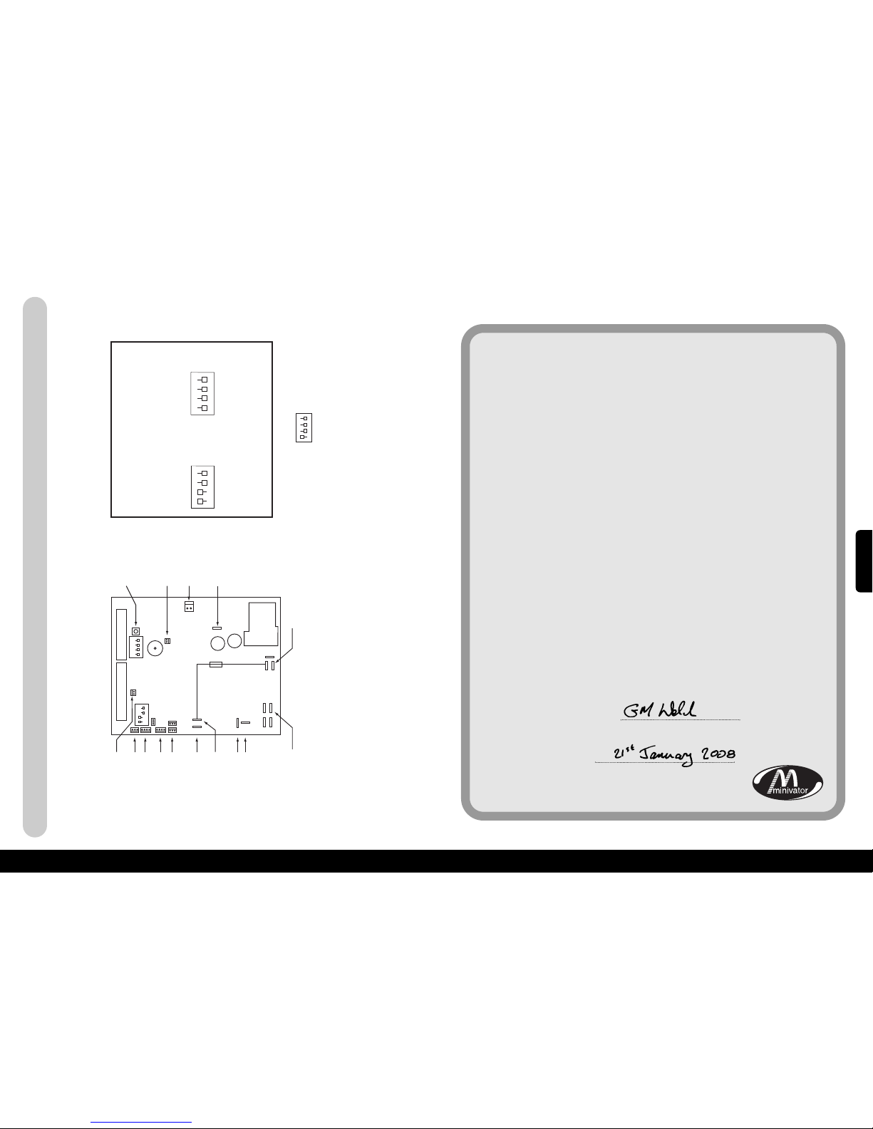
15
xAnexo 2 – Diagramas de cableadox
70
69
Simplicity
+
Opción Giratoria Automática/Estándar de la Mano Izquierda y Derecha
BOTÓN INTELIGENTE
INFRARROJO/RADIO
NO ES NECESARIA
LA CONEXIÓN
CONECTOR DEL FRENO
CARGA+
BATERÍA POSITIVO
NEGATIVO A BATERÍA
MOTOR 1 (NEGRO)
MOTOR 2 (BLANCO)
+24V CON FUSIBLE
COLECTOR DE DATOS
(CABLE GRIS)
NO ES NECESARIA
LA CONEXIÓN
CONMUTADOR
DIP 1
5A FUSIBLE
APAGACHISPAS RAPIDO
CONMUTADOR
DIP 2
NO ES NECESARIA
LA CONEXIÓN
NO ES NECESARIA
LA CONEXIÓN
CONECTOR DE 9 VÍAS
ON
ON
1 2 3 4
1 2 3 4
CONECTOR DE 8 VÍAS
INFRARROJO/RADIO
SI CAMBIA LOS CONMUTADORES DIP, POR FAVOR, DESCONECTE EL ELEVADOR,
ESPERE 10 SEGUNDOS, Y DESPUÉS CONECTE DE NUEVO EL ELEVADOR.
DIP 1
CONECTADO
1
2 3 4
DIP 2
CONECTADO
1
2 3 4
LLAVE;
CONFIGURACIÓN DEL CONMUTADORDIP ON CSE126 (PLATAFORMA GIRATORIA ELÉCTRICA).
ESTACONFIGURACION ACTIVARA EL MODO DE OSCILACIÓN ELÉCTRICA
CONECTADO
1
2 3 4
VELOCIDAD
MEDIA ARRIBA
VELOCIDAD MEDIA
ENCENDIDA
DESCONEXIÓN DE
L
A ALARMA
DESCONEXIÓN DE
LA PLATAFORMA
COLECTOR
DESCONECTADO
ELEVADOR EN LA
M
ANO IZQUIERDA
RAMPA LENTA
S
IN USO
VELOCIDAD
M
ÁXIMA ARRIBA
VELOCIDAD TOTAL
ENCENDIDA
ALARMA CONECTADA
PLATAFORMA
CONECTADA
COLECTOR
C
ONECTADO
RAMPA LENTA
R
AMPA RÁPIDA
S
IN USO
xAnexo 3 – Certificado de conformidadx
Nosotros
Minivator Ltd
de
82 First Avenue
Pensnett Estate
Kingswinford
West Midlands
DY6 7FJ, England.
Declaramos bajo nuestra responsabilidad única que el producto
Minivator Simplicity+ 950 Stairlift
Ha sido fabricado en conformidad con las siguientes
normas y especificaciones:
BS5776:1996 Sillas Elevadoras Eléctricas
ISO 9386-2 2000-11-01
A la cual se refiere esta declaración está en conformidad con
las siguientes normas nacionales:
Directriz de Compatibilidad Electromagnética 89/336/EEC
Directriz de Bajo Voltaje – 73/23/EEC
Directriz de Maquinaria – 98/37/EEC
Firmado por:
Nombre: G. Welch
Fecha:
Posición: Gerente de Ingeniería
ESPAÑOL
Page 37
71
Información importante con respecto a su silla elevadora
que debe completarse por el ingeniero de instalación.
Instalado por (Nombre de la Compañía)
No. de Serie
Fecha de instalación
Primer mantenimiento vence
Sello del Distribuidor
72
ESPAÑOL
Page 38
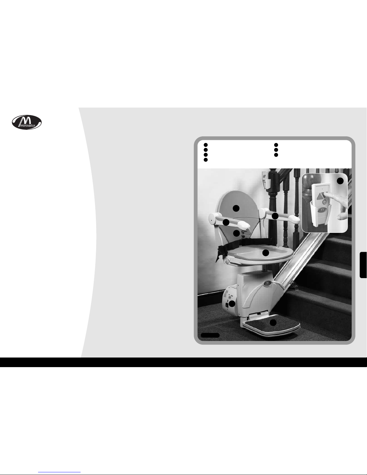
Grazie per aver scelto un elevatore
Minivator. Vi invitiamo a leggere queste
istruzioni con cura. Il vostro elevatore
Minivator è stato progettato e prodotto
con attenzione ai dettagli. Per utilizzarlo
per molti anni senza problemi, seguite le
istruzioni, dedicando particolare
attenzione ai requisiti di cura e
manutenzione. Minivator vi raccomanda di
non intraprendere alcuna operazione di
manutenzione al di fuori delle normali cure
e pulizie spiegate in questo manuale.
Per favore contattate il vostro rivenditore
Minivator oppure il nostro Servizio Clienti
nel Regno Unito al +44 08700 118282 se il
vostro elevatore richiede la nostra
attenzione: saremo felici di potervi aiutare.
Standard Britannici
Minivator è certificato conforme allo
standard internazionale di produzione
ISO 9001.
Tutti gli elevatori Minivator sono prodotti
e testati per verificarne la conformità allo
Standard Britannico per elevatori
(BS5776):1996 così come all’ISO 9386-2.
Ogni elevatore Minivator porta il
marchio CE.
Minivator viene controllata
regolarmente per garantire la continua
conformità ISO 9001, ciò garantisce ai
nostri clienti un’alta qualità e un
elevatore prodotto con precisione.
Introduzione 73
Standard Britannici 73
Caratteristiche del vostro 74
Minivator Simplicity+950
Uso del vostro 75
Minivator Simplicity+950
Interruttore a chiave 75
Interruttore acceso/spento 75
Schermo diagnostico 76
Cose da fare prima dell’uso 76
Leva d’attivazione 77
Telecomando 77
Ripiegare il vostro elevatore 78
Utilizzare la rotazione sedile 79
Operazioni manuali d’emergenza 80
Oggetti incastrati 80
Sicurezza e manutenzione 81
Avvisi e precauzioni 81
Cura ordinaria e pulizia 82
Cura e caricamento della batteria 82
Cura e pulizia 82
Smaltimento del vostro elevatore 82
Appendice 1 83
– Schermo diagnostico
Appendice 2 85
–
Diagrammi cavi
Appendice 3 88
– Certificato di conformità
73
Introduzione
74
Pagina
1
2
3
4
6
6
7
Figura 1
Caratteristiche del vostro Simplicity+ 950
Sedile ripiegabile
Sedile girevole
Telecomando a raggi infrarossi
Pedana poggiapiedi con bordini
di sicurezza
Interruttore a chiave di facile uso
Braccioli pieghevoli
Schermo diagnostico
1
2
3
4
5
6
7
5
ITALIANO
Page 39
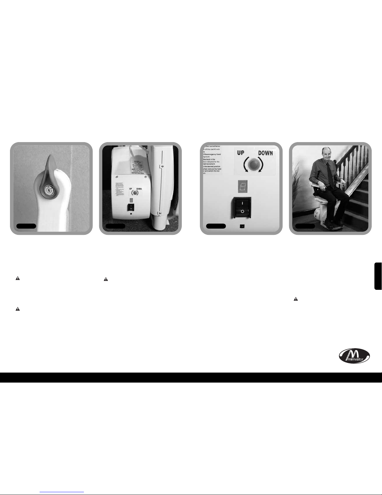
Uso del vostro Minivator Simplicity+ 950
Uso del vostro Minivator Simplicity
+ 950
Il vostro elevatore Minivator dispone di un
interruttore a chiave (Figura 2).
L’elevatore non può funzionare a meno
che la chiave sia inserita e girata in
posizione.
L’interruttore a chiave è fornito per
permettervi di bloccare l’elevatore in
modo da impedirne l’uso ad altri (per
esempio bambini).
Comunque, l’interruttore può essere
lasciato in posizione accesa se desiderato.
Se rimuovete la chiave per motivi di
sicurezza, ponetela in un posto sicuro.
Se l’interruttore a chiave è spento,
l’elevatore resterà sotto carica.
Oltre all’interruttore a chiave, il vostro
elevatore è provvisto di un interruttore
acceso / spento (Figura 3) in basso sul
pannello laterale dell’elevatore.
Assicurarsi che quest’interruttore sia
lasciato in posizione "acceso". Lo
schermo diagnostico illuminato lo
confermerà.
Se intendete stare lontano da casa per un
lungo periodo, e decidete di spegnere
l’alimentazone generale, è importante
ricordarsi di spegnere quest’interruttore.
Questo garantirà che le batterie rimangano
cariche durante la vostra assenza.
Cose da fare
prima dell’uso
Prima di utilizzare il vostro elevatore, è
MOLTO IMPORTANTE che verifichiate che
le scale siano sgombre di altre persone,
animali domestici o di oggetti che possano
ostacolare il vostro elevatore.
In seguito assicuratevi che i braccioli, la
pedana e il sedile siano aperti per garantire
la vostra sicurezza (Figura 5).
PRIMA DI UTILIZZARE IL VOSTRO
ELEVATORE ASSICURARE SEMPRE
LA CINTURA DI SICUREZZA.
76
Interruttore a chiave Interruttore
acceso/spento
75
Figura 2 Figura 3 Figura 4 Figura 5
Schermo diagnostico
L’elevatore è provvisto di uno schermo
diagnostico (Figura 4) che mostra specifici
codici in caso di guasti. Fare riferimento
all’Appendice 1 per una spiegazione dei
codici d’errore. In caso di problemi col
vostro elevatore, per favore esaminate lo
schermo e prendete nota di qualsiasi codice
di errore mostrato. Fornite all’operatore
dell’assistenza clienti questo codici quando
segnalerete un guasto.
ITALIANO
Page 40
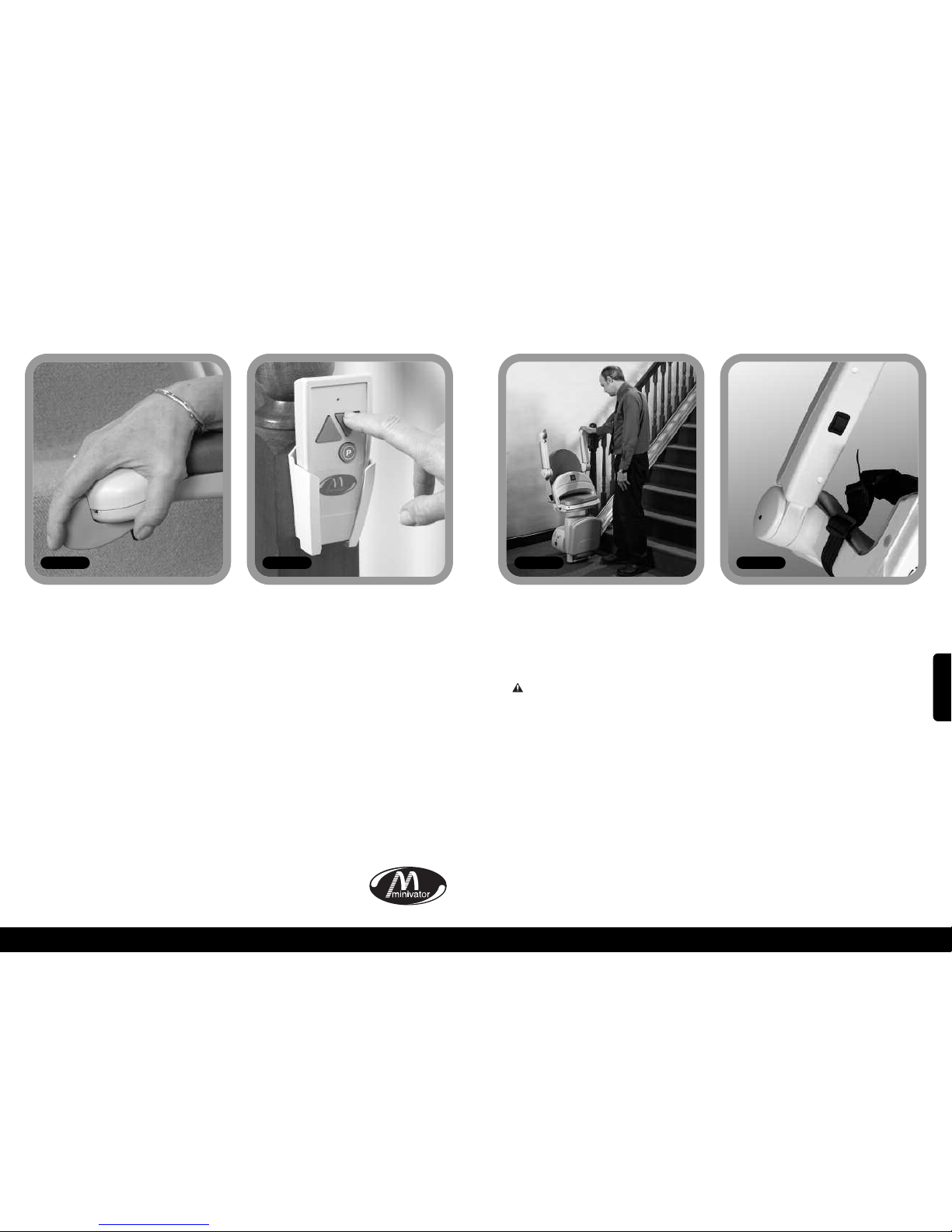
78
77
Uso del vostro Minivator Simplicity+ 950
Uso del vostro Minivator Simplicity
+ 950
Leva d’attivazione
Figura 6
Il telecomando (Figura 7) viene utilizzato
per chiamare l’elevatore verso la cima o il
fondo delle scale o per attivare la cerniera
di rotazione (se installata). Il controllo può
anche essere utilizzato da un assistente nel
caso l’utente non sia in grado di utilizzare
l’elevatore da solo.
L’assistente dovrebbe sempre rimanere al
di fuori della scalinata fino a che
l’elevatore non si sia fermato.
Sedile, braccioli e pedana del vostro
Minivator Simplicity+ 950 possono essere
ripiegati per consentire un transito
semplificato sulla scalinata quando il
sistema non è utilizzato.
PRECAUZIONE DI SICUREZZA!
RIPORTARE SEMPRE L’ELEVATORE IN
POSIZIONE RIPIEGATA, CIOÈ CON
BRACCIOLI, SEDILE E PEDANA POGGIAPIEDI
PIEGATA E CON IL SEDILE PARALLELO ALLA
PISTA DI SCORRIMENTO COME MOSTRATO
IN FIGURA 8, IN MODO DA NON OSTRUIRE
LE USCITE.
Collegamento manuale pedana
(opzionale)
Se il vostro elevatore è provvisto di un
collegamento manuale predana, la pedana
si ripiegherà automaticamente quando il
cuscino anteriore del sedile verrà sollevato.
La pedana si abbasserà quando il cuscino
anteriore del sedile verrà abbassato.
Collegamento pedana motorizzato azionato dal cuscino del sedile
(opzionale)
Se il vostro elevatore dispone di un
collegamento pedana motorizzato
azionato dal cuscio del sedile, la pedana si
ripiegherà automaticamente quando il
cuscino del sedile viene sollevato. La
pedana si abbasserà quando il cuscino
anteriore del sedile verrà abbassato.
Collegamento pedana motorizzato azionato dal bracciolo (opzionale)
Se il vostro elevatore è dotato di un
collegamento pedana motorizzato
azionato dal bracciolo, ci sarà un ulteriore
interruttore sotto il bracciolo (Figura 9). Per
abbassare la pedana poggiapiedi, usare
l’interruttore sotto il bracciolo. Per
sollevare la pedana, spostare l’interruttore
nella posizione alternativa.
Nota bene: se muovete la pedana stando
seduti sull’elevatore, assicuratevi che i
vostri piedi non ostruiscano il movimento
della pedana.
Telecomando
Ripiegare il vostro elevatore
Figura 7 Figura 8
Il vostro elevatore Minivator funziona
semplicemente premendo e tenendo
premuta la leva d’attivazione nella
direzione in cui desiderate spostarvi (Figura
6). L’elevatore si fermerà automaticamente
quando l’interruttore verrà lasciato o
quando l’elevatore avrà raggiunto la fine
della pista di scorrimento.
NOTA BENE:
Per motivi di sicurezza, l’attivazione iniziale
dell’elevatore è ritardata di 1 secondo
rispetto alla pressione della leva
d’attivazione, per evitare movimenti
accidentali. Se l’interruttore viene rilasciato
mentre l’elevatore è in movimento,
l’elevatore si arresterà e un ritardo di 1
secondo avrà luogo prima che
l’interruttore faccia riprendere il
movimento.
Cambiando direzione di spostamento, ci
sarà un ritardo di 3 secondi prima che
l’elevatore inizi a muoversi.
Figura 9
ITALIANO
Page 41
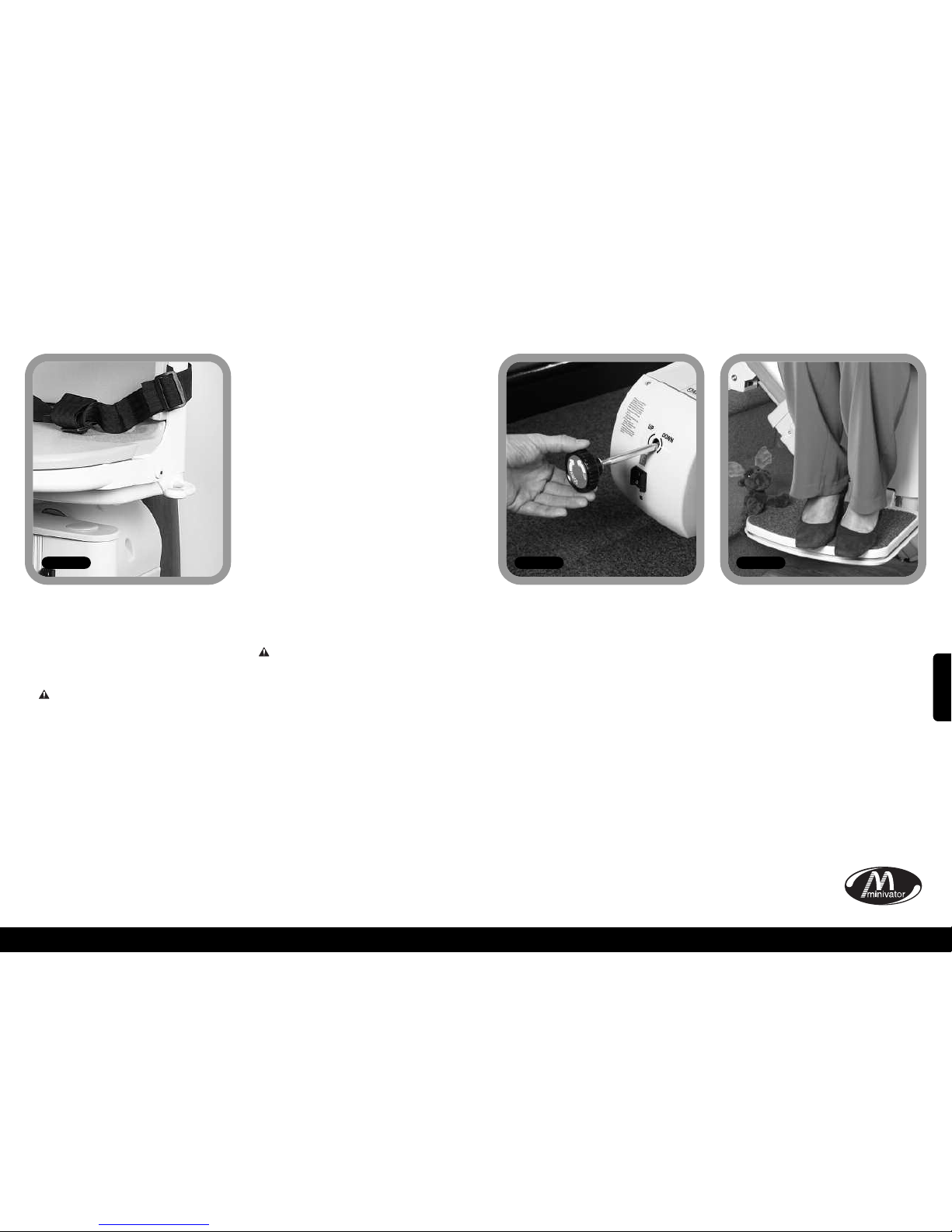
80
79
Uso del vostro Minivator Simplicity+ 950
Utilizzare la rotazione
sedile
Figura 10
Il sedile rotante vi permette di salire /
scendere dal sedile più facilmente una
volta arrivati in cima alle scale, tramite una
rotazione che vi porrà sul pianerottolo.
Per utilizzare la rotazione sedile,
attendere che l’elevatore si sia
arrestato.
Per ruotare il sedile, impugnare la leva a
sinistra o quella a destra e muoverla in alto
o in basso. Ciò sbloccherà il sedile e vi
consentirà di ruotare il sedile. Quando il
sedile raggiungerà un angolo di 90 gradi si
bloccherà in posizione.
Si raccomanda di non alzarsi dal sedile fino
a che esso non sia bloccato saldamente a
fine corsa.
Per ruotare il sedile in direzione opposta,
seguire la stessa procedura, ma spingere
per allontanarsi dal pianerottolo.
Rotazione sedile motorizzata
(opzionale)
Se il vostro elevatore è dotato di rotazione
sedile motorizzata (opzionale), non ci
saranno leve per la rotazione. Per ruotare il
sedile, mantenere l’interruttore a levella in
direzione SU. Quando l’elevatore
raggiungerà la cima delle scale, continuare
a premere l’interruttore a levetta in
direzione SU. L’elevatore produrrà tre suoni
(bip), quindi il sedile inizierà a ruotare.
Quando avrà ruotato per 90 gradi, il sedile
si arresterà.
Si raccomanda di non alzarsi dal sedile fino
a che la rotazione non è completa.
Per ruotare in direzione opposta seguire la
procedura inversa. Premere la leva
operativa in direzione GIU’. Il sedile
produrrà tre suoni (bip) e, dopo una breve
pausa, ruoterà fino alla posizione di guida.
Continuare a mantenere la leva di
comando in posizione GIU’. L’elevatore
produrrà nuovamente tre suoni (bip) prima
di iniziare la discesa.
PRECAUZIONI PER LA SICUREZZA
MAI
far ruotare il sedile senza la cintura di
sicurezza allacciata.
MAI
salire o scendere dal sedile rotante a meno
che sia bloccato in posizione.
MAI
provare ad utilizzare la rotazione del sedile
quando l’elevatore è in movimento. (Per
precauzione, se doveste provare ad
utilizzare la rotazione mentre l’elevatore è
in movimento, l’elevatore si arresterà).
MAI
provare a spostarsi su o giù lungo la
scalinata se il sedile non è in posizione
corretta (rivolto verso la direzione in cui ci
si sposta).
Uso del vostro Minivator Simplicity+ 950
Nell’improbabile evenienza che l’elevatore
subisca una completa mancanza di
alimentazione o che si porti a fine corsa
sulla guida di scorrimento, esiste una
procedura di emergenza per lo
spostamento manuale. Eseguire le
operazioni seguenti:
1. Spegnere l’elevatore con l’interruttore a
chiavetta.
2. Inserire la manopola per spostamenti
d’emergenza (Figura 11).
3. Ruotare la manopola nella direzione in
cui si desidera spostare l’elevatore.
4. Quando la posizione desiderata è stata
raggiunta, rimuovere la manopola e
accendere l’elevatore con l’interruttore
a chiave.
In caso di dubbi contattare il vostro
rivenditore d’area autorizzato Minivator
oppure chiamate Minivator allo
08700 118282.
Il vostro elevatore dispone di bordini di
sicurezza lungo la pedana poggiapiedi e
sul corpo dell’elevatore; tali bordini di
sicurezza arresteranno l’elevatore in caso ci
siano degli oggetti incastrati presso la
pedana (Figura 12).
Per rimuovere gli oggetti incastrati,
guidare l’elevatore allontanandosi
dall’oggetto, e far rimuovere l’oggetto
dalla scalinata. Procedere poi normalmente
all’uso dell’elevatore.
Operazioni manuali
d’emergenza
Oggetti incastrati
Figura 11 Figura 12
ITALIANO
Page 42
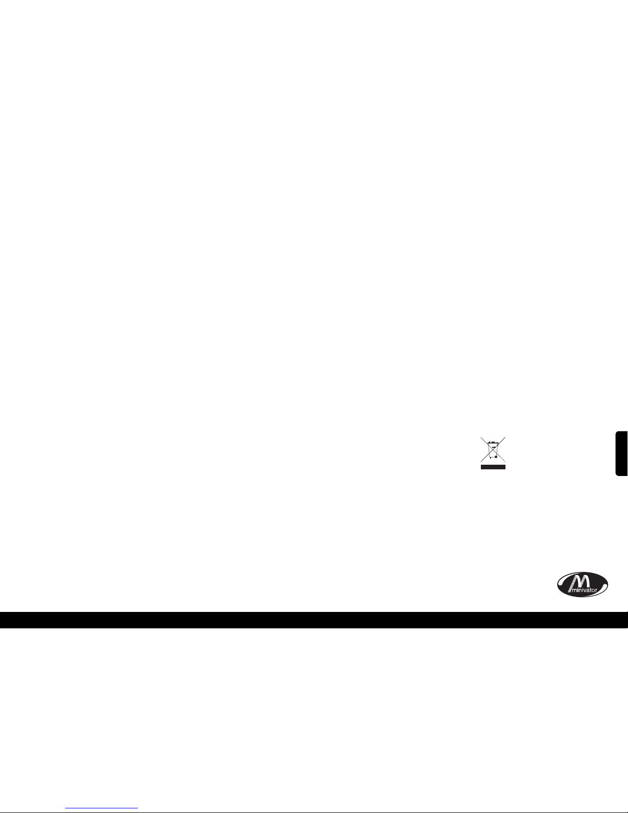
82
81
xSicurezza e manutenzionex
Si raccomanda di far eseguire un controllo periodico dopo i primi 12 mesi d’uso e, in seguito,
ALMENO OGNI 12 MESI.
Questo controllo deve essere eseguito da una persona competente, cioè da un rivenditore
autorizzato Minivator.
In caso di dubbi, contattare il Servizio Assistenza Minivator allo 08700 118282.
Se possedete il vostro elevatore e non ne avete più bisogno, il vostro rivenditore o Minivator
stessa potrebbero essere interessati ad acquistarlo.
Avvisi e precauzioni
MAI
Consentire a più di una persona di utilizzare l’elevatore nello stesso momento.
La massima capacità di carico è 120 Kg.
MAI
Consentire a bambini di giocare con o sull’elevatore.
MAI
Permettere che l’acqua venga in contatto con i componenti dell’elevatore. Se l’utente deve
trasportare liquidi, lo faccia CON ATTENZIONE.
MAI
Porre oggetti nella o sulla guida, o lasciare oggetti sulle scale, dove potrebbero venire in
contatto con l’elevatore in funzione. Il vostro elevatore è dotato di bordi laterali ed
inferiori sensibili, che lo fermerebbero in caso di rilevamento di ostacoli.
MAI
Usare l’elevatore senza allacciare la cintura di sicurezza o le altre allacciature di sicurezza
installate.
MAI
Usare l’elevatore stando in piedi.
SEMPRE
Mantenere i vostri piedi SULLA PEDANA POGGIAPIEDI quando l’elevatore è in movimento,
e cercate di evitare che i vostri piedi superino i bordi della pedana.
MAI
Ruotare il sedile prima che si sia arrestato in cima o in fondo alle scale.
SEMPRE
Ripiegare il sedile quando non lo si usa, per evitare di ostruire le uscite.
AVVISO
Se il controllo di velocità è attivo, solo una persona competente (un rivenditore autorizzato
Minivator) dovrebbe reimpostarlo. L’attivazione del controllo di velocità è indicata
dall’impossibilità di guidare l’elevatore verso il basso e dal codice d’errore 0 nello schermo
diagnostico.
xCura ordinaria e puliziax
Cura e caricamento
della batteria
Il vostro elevatore Minivator è spinto da
batterie e continuerà a funzionare per un
certo periodo anche in caso di mancanza di
corrente elettrica. Dovrebbe esservi possibile
spostarvi verso la cima e verso il fondo della
scala almeno 10 volte senza bisogno di
ricaricare le batterie. In particolare in caso di
mancanza di corrente, dovete assicurarvi che vi
sia sufficiente luce per permettere spostamenti
in sicurezza, soprattutto alle estremità della
scala, dove salirete e scenderete dall’elevatore.
La guida di scorrimento del vostro elevatore
dispone di punti di caricamento, di solito in
cima e in fondo alla scalinata. Il vostro
elevatore dovrebbe essere lasciato in sosta in
uno di questi due punti di caricamento
quando non in uso, in modo che le batterie
vengano caricate. Se l’elevatore produce un
suono (bip) continuo e/o lo schermo
diagnostico mostra un “2” quando l’elevatore
viene lasciato presso un punto di caricamento
senza usarlo, LE BATTERIE NON SONO IN FASE
DI CARICA. Verificare per favore che
l’alimentazione dell’elevatore sia accesa. Se è
accesa e il suono continua, per favore
contattate il vostro rivenditore di fiducia o il
Servizio Assistenza Minivator allo
08700 118282.
Manutenzione
Nel vostro elevatore non ci sono parti che
possano essere mantenute dall’utente. Se
l’elevatore mostra danni visibili oppure
produce suoni inconsueti o funziona in modo
inusuale, contattare Minivator o il vostro
rivenditore autorizzato immediatamente. Si
raccomanda di far eseguire un controllo
periodico dopo i primi 12 mesi e in seguito
ALMENO OGNI 12 MESI.
Cura e pulizia
Prima di pulire qualsiasi parte del vostro
elevatore Minivator, per favore verificate di
aver rimosso la chiave.
L’elevatore Minivator è prodotto con vari
materiali, tutti con superfici facilmente
pulibili. Il sedile e la copertura dell’elevatore
possono essere puliti con un panno umido,
N
ON BAGNATO, e con una piccola quantità di
l
iquido detergente.
NON UTILIZZARE prodotti per la pulizia
abrasivi, sbiancanti o prodotti per la pulizia
contenenti solventi, in quanto possono
danneggiare il sedile.
Per pulire la pista di scorrimento, inviare prima
l’elevatore in cima alle scale. La guida può
essere pulita con un panno umido. Quando la
magior parte della guida sarà pulita, spostate
l’elevatore fino in fondo alle scale e
completare la pulizia della guida assicurandosi
che non cadano scorie e residui nella guida.
Per mantenere il vostro elevatore Minivator in
buone condizioni meccaniche, si
raccomandano controlli e manutenzione
periodica eseguita da personale tecnico
qualificato.
Smaltimento del
vostro elevatore
Il vostro elevatore è stato prodotto utilizzando
materiali e componenti di alta qualità che
possono essere riciclati e riutilizzati.
Il simbolo del cassonetto con una
croce sopra indica che il vostro
elevatore è coperto dalla Direttiva
Europea 2002/96/EC, che governa lo
smaltimento di materiale elettrico
ed attrezzatura elettronica.
Ciò significa che il vostro elevatore non può
essere smaltito con il resto delle scorie
domestiche ma deve invece essere smaltito in
modo appropriato per essere riciclato.
Riciclare questo prodotto aiuta a proteggere
l’ambiente garantendo che tutti i materiali
contenuti nell’elevatore siano gestiti in modo
appropriato.
Per favore contattate Minivator al numero
08700 118282, il vostro rivenditore o il vostro
Comune per ulteriori informazioni sullo
smaltimento.
ITALIANO
Page 43
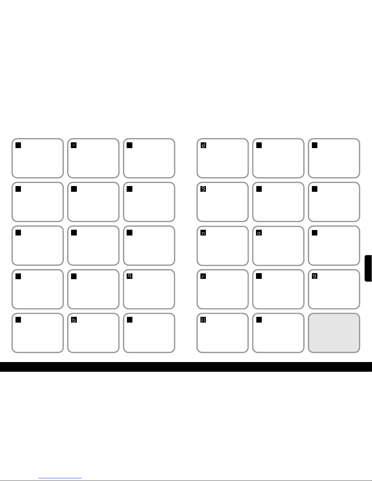
12
11
83
xAppendice 1 – Schermo diagnosticox
Codice:
Nessuno
Significato:
No display.
Auto-aiuto:
Premetel’interruttore della leva e verificate
che il monitor sia acceso. Verificate che ci
sia corrente e che il montascale sia
a
cceso. Se il problema persiste, contattate
il vostro rivenditore Minivator.
Codice:1Significato:
Ricaricare batterie.
Auto-aiuto:
Le batterie del montascale devono essere
ricaricate. Portare l’apparecchiatura ad
uno dei punti di carica. Se non
visualizzate il codice di ‘okay’, contattate
il vostro rivenditore o Minivator.
Codice:
Okay
Significato:
Okay.
A
uto-aiuto:
Contattare il vostro rivenditore o
Minivator.
Codice:0Significato:
Limite finale attivatoo
cavo di corto circuito.
Auto-aiuto:
Assicuratevi che la l’interruttore a
c
hiave sia attivato e che il sedile sia
ruotato in direzione di marcia. Se il
problema persiste, contattate il vostro
rivenditore Minivator.
0
1
Codice:
4
Significato:
Bordo di sicurezza
(direzione su/giù)
attivato - pedana.
Auto-aiuto:
Contattare il vostro rivenditore o
Minivator.
4
Codice:
5
Significato:
Limite estremità
attivato.
Auto-aiuto:
Contattare il vostro rivenditore o
Minivator.
5
Codice:7Significato:
Batterie quasi scariche.
Auto-aiuto:
Le batterie del montascale devono essere
ricaricate,portare l’apparecchio ad uno
dei punti di ricarica –Se non visualizzate
il codice di ‘Okay’, contattate il vostro
rivenditoreo Minivator.
7
Codice:9Significato:
Mostra quando la
leva è attivata in
direzione giù/su.
Auto-aiuto:
Non disponibile.
Codice:
6
Significato:
Bordi di sicurezza
(direzione su/giu)
attivati - Pedana.
Auto-aiuto:
Contattare il vostro rivenditore o
Minivator.
6
Codice:2Significato:
Non in carica.
Auto-aiuto:
Il montascale non è in sosta in uno dei
punti di carica. Portarlo ad uno dei punti
di carica. Se non visualizzate il codice di
’okay’ o se il montascale si trova già in
uno dei punti di carica, contattare il
vostro rivenditore o Minivator.
Codice:3Significato:
Limite estremità
attivato.
Auto-aiuto:
Contattare il vostro rivenditore o
Minivator.
2
3
Codice:ASignificato:
Cerniera aperta.
Auto-aiuto:
Contattare il vostro rivenditore o
Minivator.
Codice:8Significato:
Mostra quando la
leva è attivata in
direzione su/giù.
Auto-aiuto:
Non disponibile.
8
A
Codice:bSignificato:
Uno degli interruttori
è attivo, per esempio
leva su, leva giù, IR su,
IR giù.
Auto-aiuto:
Contattare il vostro rivenditore o
Minivator.
Codice:CSignificato:
L’indirizzo IR
(commutatore) non
corrisponde.
Auto-aiuto:
Contattare il vostro rivenditore o
Minivator.
C
84
Codice:
d
Significato:
Il principale circuito di
potenza è chiuso.
A
uto-aiuto:
Contattare il vostro rivenditore o
Minivator.
Codice:
E
Significato:
Il principale circuito
d
i potenza non è
chiuso.
Auto-aiuto:
Contattare il vostro rivenditore o
Minivator.
E
Codice:
F
Significato:
Freno semi-conduttore
non funzionante.
A
uto-aiuto:
Contattare il vostro rivenditore o
Minivator.
f
Codice:
g
Significato:
Freno non connesso.
Auto-aiuto:
Contattare il vostro rivenditore o
Minivator.
Codice:
H
Significato:
Il principale circuito
di potenza si è chiuso
in anticipo.
Auto-aiuto:
Contattare il vostro rivenditore o
Minivator.
H
Codice:
L
Significato:
Limite di corrente
superato.
Auto-aiuto:
Contattare il vostro rivenditore o
Minivator.
l
Codice:
n
Significato:
Velocità dimezzata.
Auto-aiuto:
Se visualizzata continuamente,
contattate il vostro rivenditore o
Minivator.
Codice:
o
Significato:
Il pannello di
controllo ha un
problema di
memoria.
Auto-aiuto:
Contattare il vostro rivenditore o
Minivator.
Codice:
P
Significato:
Assenzadi risposta
dal quadro elettrico.
Auto-aiuto:
Contattare il vostro rivenditore o
Minivator.
P
Codice:
r
Significato:
Assenza di corrente
per la carica.
Auto-aiuto:
Assicurarsi che l’alimentatore sia
acceso dal contatore generale, se lo è,
contattate il vostro rivenditore o
Minivator.
Codice:
N/A
Significato:
Sovracorrente.
Auto-aiuto:
Contattare il vostro rivenditore o
Minivator.
Codice:
N/A
Significato:
Il montascale è in
modalità sospensione,
per conservare la
carica delle batterie.
Auto-aiuto:
Premere la leva o il tasto manuale per
metterlo in modalità operative.
Codice:
U
Significato:
Alimentatore
elettrico difettoso.
Auto-aiuto:
Contattare il vostro rivenditore o
Minivator.
u
Codice:
Y
Significato:
Vi sono problemi nel
software del pannello
principale.
Auto-aiuto:
Contattare il vostro rivenditore o
Minivator.
NOTA: Se il display Visualizza
solo i codici diagnostici,
deve essere nuovamente
impostato.
Portatelo ad uno dei punti di
ricarica. Impostatelo su off per
10 secondi e poi riaccendetelo.
.8.
ITALIANO
Page 44
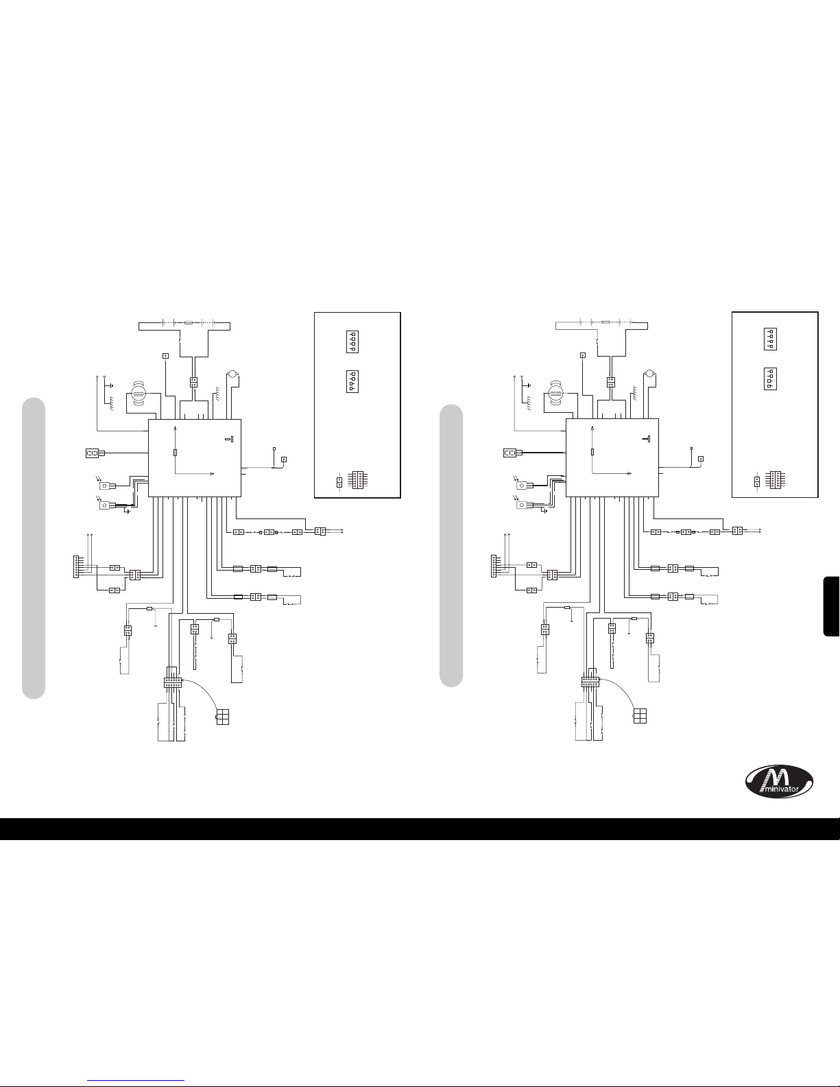
86
85
xAppendice 2 – Diagrammax
Simplicity+ Block – Ascensore lato destro
xAppendice 2 – Diagrammax
Simplicity+ Block – Ascensore lato sinistro
LIMITE INFERIORE
DELLA STRUTTURA
SOTTOCOPPA DELLA
STRUTTURA
LIMITEINFERIORE
POGGIAPIEDI
LIMITESUPERIORE POGGIAPIEDI
LIMITESICURO DEL
POGGIAPIEDESOTTO LA COPPA
CONNETTORE DEL
POGGIAPIEDI ALLA
STRUTTURA
LIMITE SUPERIORE DELLA STRUTTURA
CONNETTORE DA
STRUTTURA A SEDILE
PER CONNETTORE DEL SEDILE
PER
LIMITE
FINALE
M
F
M
F
F
CONVERSIONE
DEL TELAIO
INTERRUZIONE
DELLA ROTAIA
CARDINE/
PIATTAFORMA
LINEA DATI
DI CONTATTO
COLLEGAMENTO
GIRO
AUTOMATIZZATO
(SOLO CARATTERISTICHE AUTOMATIZZATE)
OSG
F
F
M
MFM
F
LIMITE INFERIORE
DELLA ROTAIA
LIMITE SUPERIORE
DELLA ROTAIA
PER
CONVERSIONE
DEL TELAIO
SW5
SW1
SW6
SW14
BIANCO
BIANCO
GRIGIO
FORCELLA
FORCELLA
FORCELLA
CONNETTORE
A BANANA
CONNETTORE
ABANANA
CONNETTORE
TERMINALE
ADANELLO
CONNETTORE A 9 VIE CONNETTORE A 8 VIE
FORCELLA
BIANCO
ETICHETTA
GIALLA
ETICHETTA
GIALLA
SW13
SW8
VIOLA
VISTADAL LATO
DEL CAVO
SW7
SW2
SW3
SW4
MARRONE
MARRONE
ETICHETTA
ROSSA
ETICHETTA
BLU
ETICHETTA
BLU
ETICHETTA
ROSSA
NERO
BLU
SW10
SW9
ROSSO
ROSSO
ROSSO
MARRONE
MARRONE
VIOLA
VIOLA
VIOLA VIOLA
VIOLA
VIOLA
ROSSO MARRONE
GRIGIO
VIOLA
GRIGIO
TELAIO
VIOLA
GRIGIO
RACCORDO
PER CAVO
RACCORDO
PER CAVO
SI VEDA CIRCUITO
DI DESTRA
SI VEDA CIRCUITO
DI DESTRA
MARRONE
MARRONE
ARANCIO
VERDE
BLU
VERDE
ARANCIO
BIANCO
BIANCO
DIREZIONE GIÙ VERDE
CONNETTORE
A 3 VIE
CONNETTORE
A 3 VIE
SENSORI AD
INFRAROSSI
CONNETTORE
A3 VIE
LEVADI TIPO COMUNE BLU
DIREZIONE SU ARANCIO
LIMITE DI SICUREZZA
SUPERIORE DELLA STRUTTURA MARRONE
LIMITE DI SICUREZZA DI TIPO COMUNE GRIGIO
LIMITE DI SICUREZZA
INFERIORE DELLA STRUTTURA
LIMITE INFERIORE FINALE NERO
LIMITE INFERIORE FINALE NERO
LIMITE FINALE SUPERIORE BLU
LIMITE FINALE SUPERIORE BLU
LIMITE FINALE BIANCO
1
1
12345
6
1
1 2 3
4 5 6
23456
2
2
1
1
1
1
2
3
1
1
1
2
3
4
5
6
7
8
1
1
1
2
3
2
+
5A
CAVOSCHERMATO
DISPLAYDI
DIAGNOSTICA
BK
+++
+
–
–––
–
BK
BATT
BATT
BATT
BATT
BATT
BATT
BATT
ROSSO
M2MOTOR
M1MOTOR
IR-1
I
R-2
CARDINEPROTETTO
DA FUSIBILE
D
ATICARDINE
D
IAG
C
HRG
CON-1
CON-1
CON-1
CON-2
CON-2
CON-2
CON-3
CON-3
CON-3
CON-3
CON-3
CON-3
CON-3
234567823456789
221
1
2
2
1
1
2
2
1
1
1
1
1
1 1 1 1 1
2
2
221
1
CARICA POSITIVA DEL
VOLTAGGIOIN ENTRATA
CARICA NEGATIVA
ATTRAVERSO LA
STRUTTURA
MOTORE
FRENO
1
5A
F
USIBLE
V
ELOCE
POGGIAPIEDI
AUTOMATIZZAT O CON
ALIMENTAZIONE
A +24V
ISOLAMENTO
DELLA BATTERIA
DISCONNESSIONE
PACCHETTO
BATTERIA
NERO
NERO
SW16
BIANCO
NERO
ROSSO
ROSSO
FORCELLA
BK2
B
K1
2
M+
M–
1 2
1
1
M F
CONNETTORE DELLA FORCELLA
CHIAVE:
CONNETTORE A
SPINE MULTIPLE
TUTTI I CIRCUITI DI SICUREZZA
DOVREBBERO ESSERE CHIUSI
FUNZIONI DEI DIP SWITCH SU SMT PCB
DIP 1
A
CCELERAZIONE
MEDIA
M
EZZA VELOCITÀDISCESA
D
ISABILITAZIONE
PING
DISATTIVAPEDANA
A
UTOMATICO
DISATTIVARIBALTAMENTO
A
UTOMATICO
STANDARD
RAMPALENTA
N
ON USATA
ON
1
2 3 4
DIP 2
A
CCELERAZIONE
PIENA
D
ISCESA MAXVELOCITÀ
ABILITAZIONE
P
ING
A
TTIVAPEDANA
AUTOMATICO
ATTIVA RIBALTAMENTO
A
UTOMATICO
R
AMPAVELOCE
NON USATA
ON
1
2 3 4
1 1
1
2
3
4
5
6
1
2
3
4
5
6
VIOLA
=
DITIPO COMUNE
LIMITE INFERIORE
DELLA STRUTTURA
SOTTOCOPPA DELLA
STRUTTURA
LIMITE SUPERIORE DELLA STRUTTURA
CONNETTORE DA
STRUTTURA A SEDILE
PER CONNETTORE DEL SEDILE
PER
LIMITE
FINALE
M
F
M
F
F
CONVERSIONE
DEL TELAIO
INTERRUZIONE
DELLA ROTAIA
CARDINE/
PIATTAFORMA
LINEA DATI
DI CONTATTO
COLLEGAMENTO
GIRO
AUTOMATIZZATO
(SOLO CARATTERISTICHE AUTOMATIZZATE)
OSG
F
F
M
MFM
F
LIMITE INFERIORE
DELLA ROTAIA
LIMITE SUPERIORE
DELLA ROTAIA
PER
CONVERSIONE
DEL TELAIO
SW5
SW1
SW6
SW14
BIANCO
BIANCO
GRIGIO
FORCELLA
FORCELLA
FORCELLA
CONNETTORE
A BANANA
CONNETTORE
ABANANA
CONNETTORE
TERMINALE
ADANELLO
CONNETTORE A 9 VIE CONNETTORE A 8 VIE
FORCELLA
BIANCO
ETICHETTA
GIALLA
ETICHETTA
GIALLA
CSE1
SW13
SW8
VIOLA
VISTADAL LATO
DEL CAVO
SW7
SW2
SW3
SW4
MARRONE
MARRONE
ETICHETTA
ROSSA
ETICHETTA
BLU
ETICHETTA
BLU
ETICHETTA
ROSSA
NERO
BLU
SW10
SW9
ROSSO
ROSSO
ROSSO
MARRONE
VIOLA
VIOLA
VIOLA
VIOLA
VIOLA MARRON
MARRON
ROSSO
MARRONE
MARRONE
GRIGIO
VIOLA
GRIGIO
TELAIO
MARRONE
GRIGIO
RACCORDO
PER CAVO
RACCORDO
PER CAVO
SI VEDA CIRCUITO
DI SINISTRA
SI VEDA CIRCUITO
DI SINISTRA
MARRONE
ARANCIO
ARANCIO
BLU
VERDE
VERDE
BIANCO
BIANCO
DIREZIONE GIÙ VERDE
CONNETTORE
A 3 VIE
CONNETTORE
A 3 VIE
SENSORI AD
INFRAROSSI
CONNETTORE
A3 VIE
LEVADI TIPO COMUNE BLU
DIREZIONE SU ARANCIO
LIMITE DI SICUREZZA
SUPERIORE DELLA STRUTTURA MARRONE
LIMITE DI SICUREZZA DI TIPO COMUNE GRIGIO
LIMITE DI SICUREZZA
INFERIORE DELLA STRUTTURA
LIMITE INFERIORE FINALE NERO
LIMITE INFERIORE FINALE NERO
LIMITE FINALE SUPERIORE BLU
LIMITE FINALE SUPERIORE BLU
LIMITE FINALE BIANCO
1
1
12345
6
1
1 2 3
4 5 6
23456
221
1
1
1
2
3
1
1
1
2
3
4
5
6
7
8
1
1
1
2
3
2
+
5A
CAVOSCHERMATO
DISPLAYDI
DIAGNOSTICA
BK
+++
+
–
–––
–
BK
BATT
BATT
BATT
BATT
BATT
BATT
BATT
ROSSO
M2MOTOR
M1MOTOR
IR-1
IR-2
C
ARDINE PROTETTO
D
AFUSIBILE
D
ATI CARDINE
DIAG
CHRG
CON-1
CON-1
CON-1
CON-2
CON-2
CON-2
CON-3
CON-3
CON-3
CON-3
CON-3
CON-3
CON-3
234567823456789
221
1
2
2
1
1
2
2
1
1
1
1
1
1 1 1 1 1
2
2
2
2
1
1
MOTORE
FRENO
1
5A
FUSIBLE
V
ELOCE
POGGIAPIEDI
AUTOMATIZZAT O CON
ALIMENTAZIONE
A +24V
ISOLAMENTO
DELLA BATTERIA
DISCONNESSIONE
PACCHETTO
BATTERIA
NERO
NERO
SW16
BIANCO
NERO
ROSSO
ROSSO
FORCELLA
B
K2
BK1
2
M+
M–
1 2
1
1
VIOLA
LIMITESUPERIORE
POGGIAPIEDI
LIMITEINFERIORE POGGIAPIEDI
LIMITESICURO DEL
POGGIAPIEDESOTTO LA COPPA
CARICA POSITIVA DEL
VOLTAGGIOIN ENTRATA
CARICA NEGATIVA
ATTRAVERSO LA
STRUTTURA
M F
CONNETTORE DELLA FORCELLA
CHIAVE:
CONNETTORE A
SPINE MULTIPLE
TUTTI I CIRCUITI DI SICUREZZA
DOVREBBERO ESSERE CHIUSI
FUNZIONI DEI DIP SWITCH SU SMT PCB
1 1
1
2
3
4
5
6
1
2
3
4
5
6
=
CONNETTORE DEL
POGGIAPIEDI ALLA
STRUTTURA
DIP 1
A
CCELERAZIONE
MEDIA
MEZZA VELOCITÀ DISCESA
DISABILITAZIONE
P
ING
DISATTIVA PEDANA
A
UTOMATICO
DISATTIVA RIBALTAMENTO
A
UTOMATICO
S
TANDARD
R
AMPALENTA
N
ON USATA
ON
1
2 3 4
DIP 2
ACCELERAZIONE
P
IENA
D
ISCESA MAXVELOCITÀ
A
BILITAZIONE
P
ING
A
TTIVA PEDANA
AUTOMATICO
ATTIVA RIBALTAMENTO
A
UTOMATICO
R
AMPAVELOCE
N
ON USATA
ON
1
2 3 4
DITIPO COMUNE
ITALIANO
Page 45
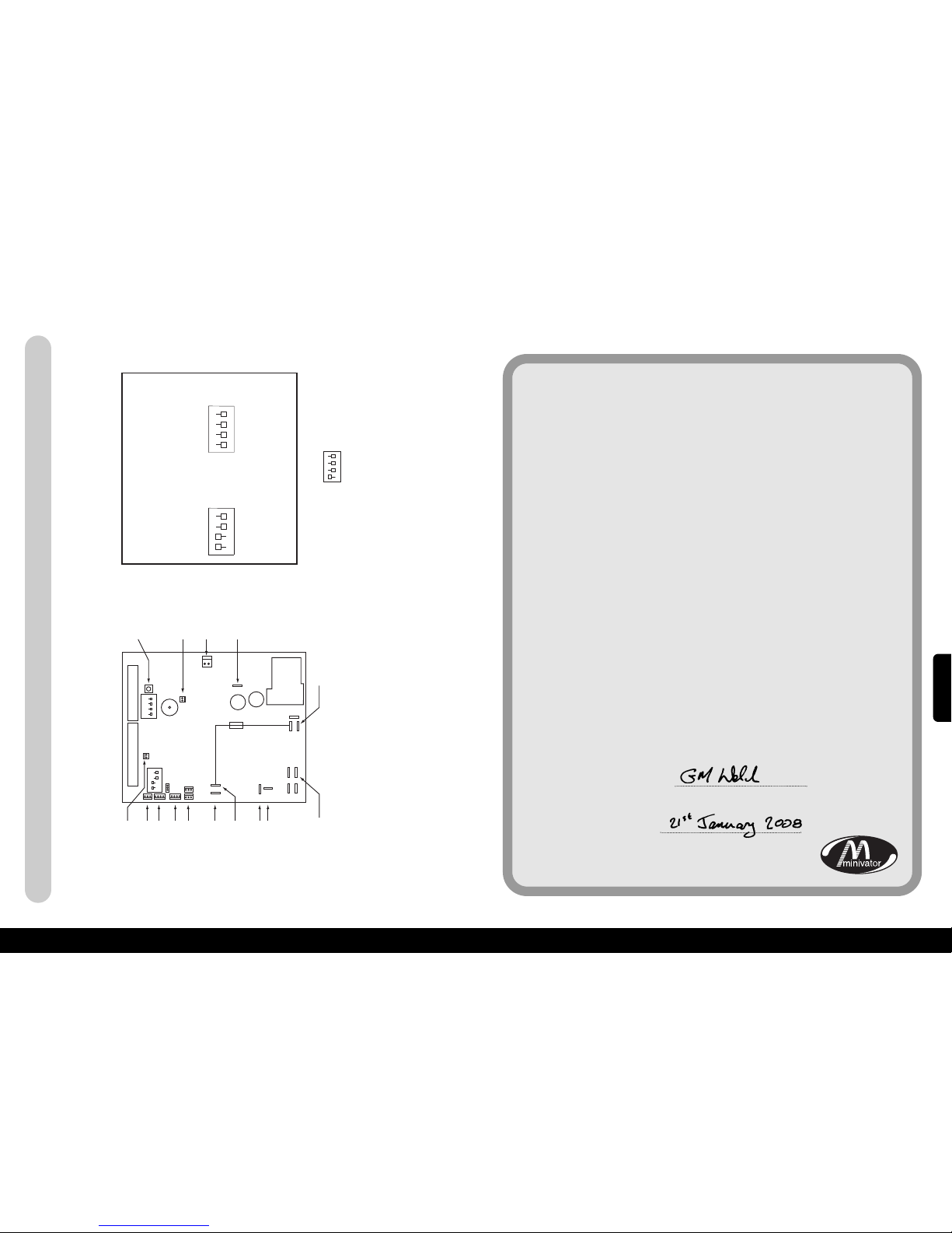
15
xAppendice 2 – Diagrammax
88
87
INFRAROSSI/PULSANTE
RADIO
NESSUN COLLEGAMENTO
RICHIESTO
CONNETTORE DEL FRENO
CARICA+
BATTERIA POSITIVA
BATTERIA NEGATIVA
MOTORE 1 (NERO)
MOTORE 2 (BIANCO)
FUSIBILI A +24V
DATI DEL CARDINE
(CAVO GRIGIO)
NESSUN COLLEGAMENTO
RICHIESTO
DIP
SWITCH 1
15A
FUSIBLE RAPIDO
DIP
SWITCH 2
NESSUN COLLEGAMENTO
RICHIESTO
DISPLAY A 7 SEGMENTI
NESSUN COLLEGAMENTO
RICHIESTO
CONNETTORE A 9 VIE
ON
ON
1 2 3 4
1 2 3 4
CONNETTORE A 8 VIE
INFRAROSSI/RADIO
SE I DIP SWITCH VENGONO CAMBIATI SI PREGA DI SPEGNERE IL MONTASCALE,
ASPETTARE 10 SECONDI, IN SEGUITO RIAVVIARE IL MONTASCALE
DIP 1
ACCESO
1
2 3 4
DIP 2
ACCESO
1
2 3 4
CHIAVE;
IMPOSTAZIONEDEL DIP SWITCH SU M CSE 126 (PANNELLO GIRO AUTOMATIZZATO)
QUESTAIMPOSTAZIONE ABILITERÀ LA MODALITÀ GIRO AUTOMATIZZATO
ACCESO
1
2 3 4
ACCELERAZIONE MEDIA
MEZZA VELOCITADISCESA
DISABILITAZIONEPING
DISABILITAZIONEPLAT
DISABILITAZIONECARDINE
MONTASCALELATO SINISTRO
RAMPA LENTA
N
ON USATA
ACCELERAZIONE PIENA
DISCESA MAX VELOCITA
ABILITAZIONE PING
ABILITAZIONE PLAT
A
BILITAZIONE CARDINE
MONTASCALE LATODESTRO
RAMPA VELOCE
N
ON USATA
xAppendice 3 – Certificato di conformitàx
Noi
Minivator Ltd
con sede
82 First Avenue
Pensnett Estate
Kingswinford
West Midlands
DY6 7FJ, England.
Dichiariamo sotto la nostra totale responsabilità che il prodotto
Montascale Simplicity+ 950
è stato prodotto in conformità alla normativa e alle
specifiche indicate di seguito:
BS5776:1996 in materia di montascale motorizzati
ISO 9386-2 2000-11-01
Ciò a cui fa riferimento la presente dichiarazione è conforme
alla seguente normativa nazionale:
Compatibilità elettromagnetica – Direttiva del Consiglio 89/336/CE
Bassa tensione – Direttiva del Consiglio 73/23/CE
Macchine - Direttiva del Parlamento Europeo e del Consiglio 98/37/CE
Firmato:
Nome: G. Welch
Data:
Ruolo: Ingegnere responsabile
Simplicity
+
Block lato sinistro e lato destro – Rotazione standard / automatica
ITALIANO
Page 46
89
Informazioni importanti sul montascale che vanno
completate a cura del tecnico che effettua l’installazione.
Installato da (Ragione Sociale)
Numero di Serie
Data di installazione
Primo intervento di manutenzione previsto il
Timbro del concessionario
ITALIANO
 Loading...