

Minipack-torre S.p.A.
Via Provinciale, 54 - 24044 Dalmine (BG) - Italy
Tel. (035) 563525 – Fax (035) 564945
E-mail: info@minip ac k - torr e.it
http://www.minipack-torre.it
ISTRUZIONE PER L’INSTALLAZIONE, L’USO E LA MANUTENZIONE
INSTALLATION, OPERATION AND MAINTENANCE
INSTALLATIONS, GEBRAUCHS UND WARTUNGSANWEISUNGEN
INSTRUCTIONS POUR L’INSTALLATION, L’EMPLOI ET L’ENTRETIEN
INSTRUCCIONES PARA LA INSTALACION, USO Y MANTENIMENTO
INSTRUÇÕES PARA A INSTALAÇÃO, O USO E A MANUTENÇÃO
Ο∆ΗΓΙΕΣ ΓΙΑ ΤΗΝ ΕΓΚΑΤΑΣΤΑΣΗ, ΤΗΝ ΧΡΗΣΗ ΚΑΙ ΤΗΝ ΣΥΝΤΗΡΗΣΗ
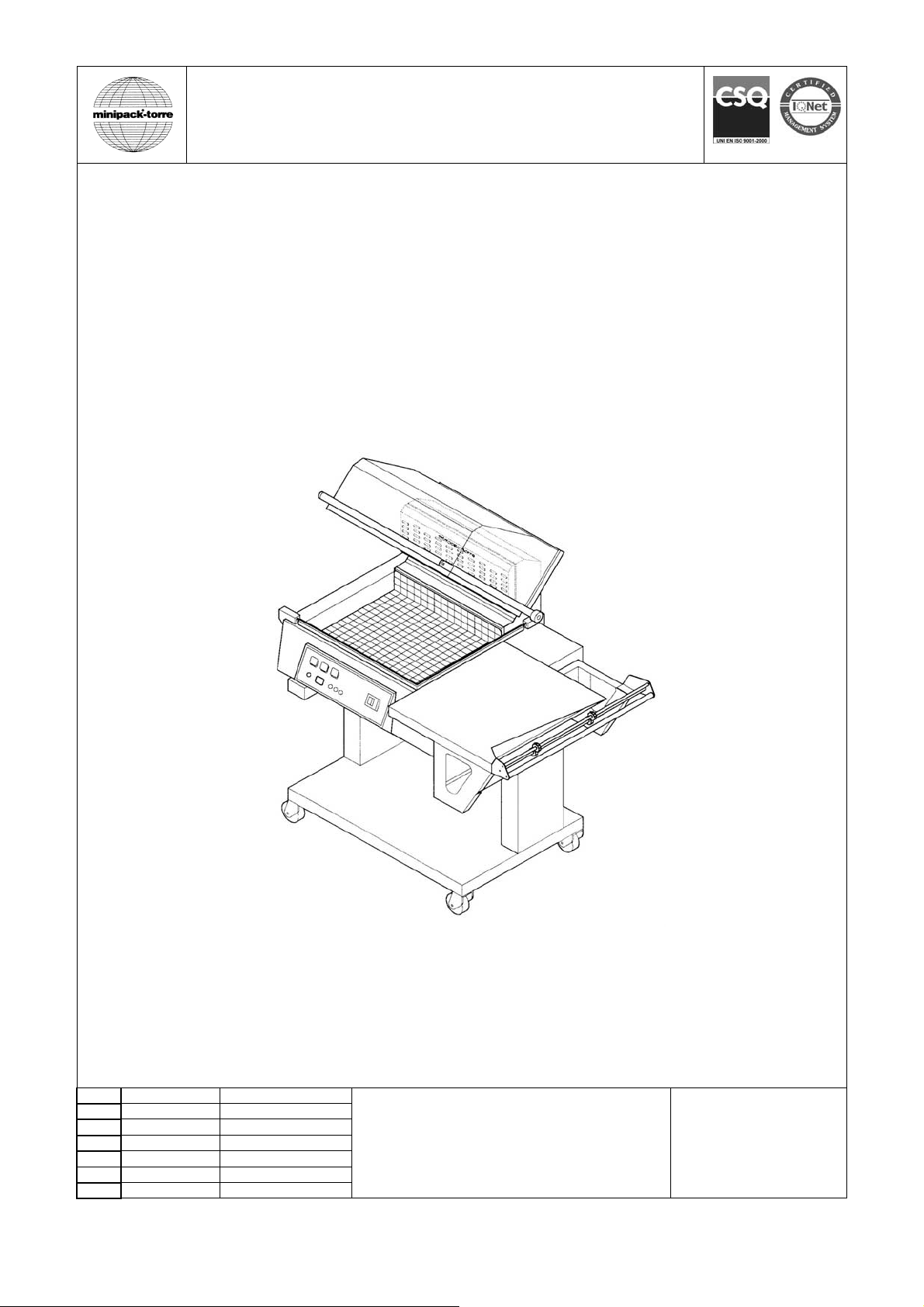
Synthesis 760
Leggere attentamente questo libretto prima di usare la macchina
Before using the machine please carefully read the instructions
Beachten Sie gut die Bedinungsa nle itu ng bev or man die Maschi ne ben ützt
Nous vous prions de bien lire le manuel d’instructions avant d’utiliser la machine
∆ιαβάστε µε προσοχή τις παρακάτω οδηγίες χρήσεως πριν χρησιµοποιήσετε τη συσκευή
I Italiano Pagina 01
GB English Page 09
D Deutsch Seite 17
F Français Page 25
E Español Página 33
P Português Página 41
GR Ελληνικά Σελίδα 49
Leer atentamente este manual antes de usar la máquina
Antes de usar a máquina ler cuidadosamente este livrete
DOC. N. FM111053
REV. 02
ED. 01.2005

Indice
Capitolo 1. Introduzione
1.1. Prefazione pagina 02
1.2. Prestazioni della macchina confezionatrice pagina 02
1.3. Identificazione della macchina pagina 02
1.4. Peso e dimensioni della macchina imballata pagina 02
1.5. Peso e dimensioni della macchina pagina 02
Capitolo 2. Installazione della macchina
2.1. Trasporto e posizionamento pagina 03
2.2. Condizioni ambientali pagina 03
2.3. Collegamento elettrico pagina 03
Capitolo 3. Regolazione ed approntamento macchina
3.1. Regolazione pagina 04
3.2. Inserimento bobina film pagina 05
3.3. Posizionamento del piatto retinato pagina 05
3.4. Regolazione supporto bobina e piatto di confezionamento pagina 05
3.5. Esecuzione 1^ saldatura film pagina 05
3.6. Introduzione dell’oggetto da confezionare pagina 05
3.7. Confezionamento pagina 05
Capitolo 4. Limitazioni e condizioni d’uso della macchina
4.1. Dimensioni max. della confezione pagina 05
4.2. Ciò che non si deve confezionare pagina 05
Capitolo 5. Caratteristiche del film
5.1. Films da adoperare pagina 06
5.2. Calcolo della fascia A pagina 06
Capitolo 6. Norme di sicurezza
6.1. Avvertimenti pagina 06
Capitolo 7. Manutenzione ordinaria
7.1. Cautele per interventi di manutenzione ordinaria pagina 06
7.2. Pulizia lama saldante pagina 07
7.3. Rimozione di sfridi di film plastico e vari pagina 07
7.4. Pulizia della macchina pagina 07
7.5. Cambio teflon e gomma pagina 07
7.6. Cambio lama saldante pagina 07
7.7. Schema elettrico pagina 07
7.8. Particolari di ricambio pagina 08
7.9. Smontaggio, demolizione e smaltimento residui pagina 08
Capitolo 8. Garanzia
8.1. Certificato di garanzia pagina 08
8.2. Condizioni di garanzia pagina 08
1

Capitolo 1. Introduzione
1.1. Prefazione
Il presente manuale è redatto nel rispetto della norma UNI 10893 del Luglio 2000. È rivolto a tutti gli utilizzatori al fine di
consentire un corretto uso della macchina. Conservarlo in luogo facilmente accessibile vicino alla macchina e noto a
tutti gli utilizzatori. Il presente manuale è parte integrante della macchina ai fini della sicurezza.
Per migliorare la comprensione precisiamo di seguito i simboli utilizzati.
ATTENZIONE:
Norme antinfortunistiche per l’operatore. Tale avvertimento indica la presenza di pericoli che
possono causare lesioni a chi sta operando sulla macchina.
ATTENZIONE:
Organi caldi. Indica il pericolo di ustioni con rischio di infortunio, anche grave per la persona
esposta.
AVVERTENZA:
Indica la possibilità di arrecare danno alla macchina e/o ai suoi componenti.
Tutti i diritti di riproduzione del presente manuale sono riservati alla ditta costruttrice. La riproduzione, anche parziale, è
vietata a termini di legge. Le descrizioni e le illustrazioni presenti in questo manuale non sono impegnative, di
conseguenza la ditta costruttrice si riserva il diritto di apportare in qualsiasi momento tutte le modifiche che riterrà
opportune. Il presente manuale non può essere ceduto in visione a terzi senza autorizzazione scritta della ditta
costruttrice. La macchina deve essere utilizzata solo per soddisfare le esigenze per cui è stata concepita, ogni altro uso
è da considerarsi “uso improprio”, quindi pericoloso.
Prima di compiere qualsiasi operazione sulla macchina è obbligatorio leggere attentamente tutte le istruzioni del
presente manuale, al fine di evitare possibili danneggiamenti alla macchina stessa, alle persone ed alle cose.
Non è consentito operare in caso di dubbi sulla corretta interpretazione delle istruzioni.
Interpellare il fabbricante per ottenere i necessari chiarimenti.
Al momento della consegna verificare che la macchina sia completa in tutte le sue parti.
Eventuali anomalie dovranno essere presentate immediatamente al fornitore.
La ditta costruttrice declina ogni responsabilità per uso improprio della macchina e/o per danni causati in seguito ad
operazioni non contemplate in questo manuale.
1.2. Prestazioni della macchina confezionatrice
Avete acquistato una macchina dalle caratteristiche e prestazioni eccezionali e Vi ringraziamo per la preferenza
accordataci. Il sistema di confezionamento è unico nel suo genere e si è affermato nel mondo con la presenza di oltre
60000 macchine operanti nel campo dell’imballaggio e del confezionamento. Esso è pratico, super economico e
razionale ed è coperto da brevetti Nazionali ed Internazionali.
La validità del concetto tecnologico oltre che la qualità dei componenti e materiali impiegati nel processo produttivo e di
collaudo sono la migliore garanzia di un buon funzionamento e affidabilità nel tempo.
La macchina può essere utilizzata come macchina per saldatura e termoretrazione del film contemporanee, oppure
come semplice macchina saldatrice grazie al suo particolare circuito di funzionamento. In questo ultimo caso è possibile
racchiudere l’oggetto in sacchetti flosci senza termoretrazione.
La macchina può arrivare ad eseguire fino a 300 confezioni/ora.
1.3. Identificazione della macchina
Per qualsiasi comunicazione con il costruttore, citare sempre il modello della macchina e il numero di matricola indicati
sulla targhetta applicata nella parte posteriore della macchina (figura 1.3. pag.58).
1.4. Peso e dimensioni della macchina imballata
a = mm1350 b = mm960 c = mm820 Peso = Kg134 (figura 1.4. pag.58).
1.5. Peso e dimensioni della macchina
a = mm1280 b = mm780 c = mm1400 Peso = Kg100 (figura 1.5. pag.58).
2
Capitolo 2. Installazione della macchina
2.1. Trasporto e posizionamento
Nel trasporto e nel posizionamento della macchina si raccomanda di manovrare con molta cautela!
Nella movimentazione della macchina utilizzare guanti di protezione.
! Tagliare con la forbice la reggia (avendo cura di proteggersi gli occhi con degli occhiali) e sfilare il cartone (figura
2.1.A pag.58).
! Togliere la scatola contenente il carrell o (figura 2.1.B pag. 58).
! Svitare le 4 viti di fissaggio (B) al pallet, riportando all’interno della macchina le 4 piastrine (C) (figura 2.1.B pag.58).
! Assemblare il carrello (figura 2.1.C pag.58).
Sollevare la macchina e posizionarla sul carrello facendo attenzione che i 4 piedini siano ben inseriti nei loro
alloggiamenti. Liberare la campana super iore tagliando la cordina di ritegno.
Se si trasporta a mano è necessario l’intervento di 4 persone.
Per sollevare la macchina fare presa sempre alle estremità e comunque mai tramite il supporto bobina
(5).
2.2. Condizioni ambientali
! Posizionare la macchina accertandosi che sia livellata sul pavimento, in un ambiente adatto, privo di umidità,
materiali infiammabili, gas, esplosivi.
! Lasciare uno spazio minimo di 200mm attorno alla macchina, per non ostruire le prese d’aria (figura 2.2. pag.58).
! Bloccare la macchina, una volta ottenuto il corretto posizionamento, agendo sul freno delle ruote.
Condizioni consentite negli ambienti in cui é collocata la macchina:
! Temperatura da + 5°C a + 40°C
! Umidità relativa da 30% a 90% senza condensazione.
L’illuminazione del locale di utilizzo deve essere conforme alle leggi vigenti nel paese in cui è installata la macchina e
deve comunque essere uniforme e garantire una buona visibilità, per salvaguardare la sicurezza e la salute
dell’operatore.
GRADO DI PROTEZIONE DELLA MACCHINA = IP20
IL RUMORE AEREO PRODOTTO DALLA MACCHINA È INFERIORE A 70 dB
2.3. Collegamento elettrico
RISPETTARE LE NORME PER LA SICUREZZA SUL LAVORO!
Se la macchina non è dotata della spina di alimentazione utilizzare una spina adeguata ai valori di tensione
e amperaggio descritti nella targhetta dati e comunque conforme alle normative vigenti nel paese
d’installazione.
È OBBLIGATORIA LA MESSA A TERRA! (figura 2.3. pag.58).
Prima di effettuare il collegamento elettrico assicuratevi che la tensione di rete corrisponda al voltaggio indicato sulla
targhetta applicata nella parte posteriore della macchina e che il contatto di terra sia conforme alle norme di sicurezza
vigenti. In caso di dubbi sulla tensione di rete contattate l’ente locale distributore dell’energia elettrica.
3
Capitolo 3. Regolazione ed approntamento macchina
3.1. Regolazione
1 Interruttore generale
2 Pulsante di regolaz ione
3 Pulsante di regolaz ione
A Spia temperatura
B Spia retrazione
C Spia saldatura
P Pulsante di selezione programmi
D Display
S Pulsante di selezione variabili
(figura 3.1. pag.59).
CARATTERISTICHE SCHEDA ELETTRONICA
La macchina ha 6 programmi selezionabili:
N° Programma Caratteristiche Programma
P1
P2
P3
P4
P5
P6
Il programma più completo è composto da 4 variabili modificabili (qualora una variabile non fosse impostabile,
chiaramente non comparirà):
Variabile Campo Caratteristiche Campo
1. Temperatura
2. Saldatura
3. Retrazione
4. Ritardo Retrazione
Solo saldatura
Saldatura + retrazione
Saldatura + retrazione ritardata a fine saldatura
Saldatura + retrazione
Saldatura + retrazione
Saldatura + retrazione
00 ÷ 99
0 ÷ 2.2
0.0 ÷ 9.9
0 ÷ 9
corrisponde a 200.....400°C (2°C per punto)-(valore medio 75)
valori espressi in secondi
valori espressi in secondi
valori espressi in decimi di secondo
FASE 1 = ACCENSIONE DELLA MACCHINA
Ruotare l’interruttore generale (1) nella posizione 1.
Prima di usare la macchina attendere che arrivi alla temperatura impostata segnalata dallo spegnimento della spia (A). Il
display (D) si accende e compare il n° di programma attivo.
FASE 2 = SELEZIONE PROGRAMMI
Per selezionare il n° di programma premere il pulsante (P).
FASE 3 = PROGRAMMAZIONE VARIABILI
Con il pulsante (S) si scorrono le variabili del programma scelto e con i pulsanti (2) e (3) si modificano i valori
memorizzati.
Per convalidare le modifiche premere il pulsante (S) fino a far comparire sul display il n° di programma.
Il tempo di ritardo ventola dopo la saldatura é una variabile modificabile che non ha un led associato e pertanto viene
indicato con una “ r ” sul display sinistro, mentre il display destro indica il tempo impostato.
Al termine di tutte le variabili programmabili il display mostrerà nuovamente il codice del programma appena editato (es.
P1).
N.B.: Se durante la programmazione viene premuto il fine corsa SQ1 l’apparecchio esce dalla programmazione e il
programma selezionato va immediatamente in esecuzione rimostrando sul display il numero del programma.
FASE 4 = ESECUZIONE
Eseguite tutte le regolazioni la macchina é pronta per procedere al confezionamento.
TABELLA INDICATIVA DELL’IMPOSTAZIONE CICLO MACCHINA
TEMPO DI RETRAZIONE TEMPO DI PAUSA TEMPERATURA (Campo)
6” 6” 50
5” 7” 60
4” 8” 70
3” 9” 80
2” 10” 90
In caso di “ANOMALIA ” sul display compaiono le seguenti sigle:
E 1 La macchina è stata accesa con la campana abbassata. Alzare la campana.
E 2 La macchina è stata accesa col pulsante (S) premuto.
Rilasciare il pulsante. Se permane la segnalazione di errore controllare il funzionamento del pulsante.
E 3 La temperatura di lavoro non è stata raggiunta nel tempo stabilito (10 min.).
Controllare che la sonda sia posizionata correttamente. Controllare la resistenza di riscaldamento. Controllare i
fusibili. Il ripristino avviene premendo il pulsante (P).
E 4 La temperatura ha superato i 430°C oppure la sonda è interrotta.
Il ripristino avviene riavviando la macchina.
4

Capitolo 3. Regolazione ed approntamento macchina
3.2. Inserimento bobina film
! Inserire la bobina di film sul rullo (6) bloccandola mediante i coni centratori (7) (figura 3.2. pag.59).
! Posizionare il rullo sul supporto bobina.
! Passaggio attraverso i microforatori (8).
! Passaggio del lembo inferiore del film sotto il piatto di confezionamento (9).
! Passaggio del lembo superiore del film sopra il piatto di confezionamento (9).
3.3. Posizionamento del piatto retinato
Il piatto retinato (11) può essere posizionato a seconda dell’oggetto da confezionare.
Per il suo posizionamento agire come segue (figura 3.3. pag.59):
! Tirare il piatto secondo le frecce
! Rimuovere il piatto dai riscontri
! Riposizionare il piatto sui riscontri all’altezza desiderata
N.B.: Per una buona confezione il piatto retinato deve essere posizionato in modo che la saldatura del film si trovi a metà
dell’altezza della confezione.
3.4. Regolazione supporto bobina e piatto di confezionamento
Il supporto bobina (5) e il piatto di confezionamento (9) devono essere regolati in funzione della larghezza (A)
dell’oggetto da confezionare, lasciando circa 1-2 cm di spazio tra l’oggetto ed il bordo di saldatura (figura 3.4. pag.59).
3.5. Esecuzione 1^ saldatura film
Per eseguire la 1^ saldatura portare il film come indicato in figura (figura 3.5. pag.59). Abbassare la maniglia della
campana con la mano sinistra e premere con una pressione di 10-15 Kg. La macchina entrerà automaticamente in
funzione e realizzerete la 1^ saldatura sul lato sinistro del film. Con la mano destra aiutate il distacco del film dalla lama
saldante. Ora il film è pronto per procedere al confezionamento.
3.6. Introduzione dell’oggetto da confezionare
Sollevare con la mano sinistra il bordo del film sul piatto di confezionamento.
Introdurre con la mano destra il prodotto nel film e farlo scorrere verso sinistra fino a depositarlo sul piatto retinato
lasciando circa 1-2 cm di spazio tra il prodotto ed il telaio interno di saldatura in modo da permettere il passaggio dell’aria
per la termoretrazione (figura 3.6. pag.59).
3.7. Confezionamento
Premendo sulla maniglia della campana con una pressione di circa 15 Kg. questa va ad appoggiarsi sulla lama saldante
(figura 3.7. pag.59). In questo modo avviene automaticamente la saldatura del film sui lati aperti (destro e di fronte).
Se avete selezionato la funzione “SALDATURA + RETRAZIONE” vedrete il film retrarsi attorno al prodotto, diminuite
allora leggermente la pressione sulla maniglia della campana in modo da permettere lo stacco del film dalla zona di
saldatura all’interno. Con la mano destra aiutate il distacco del film dalle lame saldanti verso l’esterno.
Capitolo 4. Limitazioni e condizioni d’ uso della macchina
4.1. Dimensioni max. della confezione
a = mm 500 b = mm 380 c = mm 250 (figura 4.1. pag.59).
N.B.: le misure indicate nella tabella si riferiscono alla misura max. della singola dimensione.
Per la misura max della confezione (b x c) bisogna comunque fare riferimento al capitolo 5.2., dove si vede che, la
somma di (b + c) é comunque uguale alla larghezza della bobina del film meno 100 mm.
4.2. Ciò’ che non si deve confezionare
E’ assolutamente vietato confezionare i seguenti tipi di prodotti per evitare di danneggiare in modo permanente la
macchina, oltre che provocare rischi di infortuni all’operatore addetto:
• Prodotti bagnati e instabili
• Liquidi di qualsiasi tipo e densità in contenitori fragili
• Materiali infiammabili ed esplosivi
• Bombolette con gas a pressione o di qualsiasi tipo
• Polveri sciolte e volatili
• Materiali sciolti con dimensioni più’ piccole dei fori del piatto retinato
• Eventuali materiali e prodotti non previsti che possano in qualche modo essere pericolosi per
l’utente e provocare danni alla macchina stessa
5
Capitolo 5. Caratteristiche del film
5.1. Films da adoperare
La macchina può lavorare con tutti i films termoretraibili con spessore da 15 a 50 micron sia di tipo tecnico che
alimentare.
Per garantire i migliori risultati è consigliato l’utilizzo dei films commercializzati dalla MINIPACK-TORRE S.p.A.
Le speciali caratteristiche dei nostri films (anche con disegni e scritte personalizzate del cliente) danno garanzie di
affidabilità sia dal lato della corrispondenza alle normative di legge vigenti, che dal lato sicurezza di ottimo
funzionamento delle nostre macchine.
Si raccomanda di consultare le schede tecniche e di sicurezza dei films utilizzati e di attenersi alle
prescrizioni descritte!
A = mm600 MAX D = mm250 MAX d = mm77 (figura 5.1. pag.60).
5.2. Calcolo della fascia A
Fascia A = b + c + 100mm (figura 5.2. pag.60).
Capitolo 6. Norme di sicurezza
6.1. Avvertimenti
Durante le fasi di lavoro porre attenzione a tutte le parti calde della macchina che
possono raggiungere temperature tali da provocare ustioni.
Durante il funzionamento della macchina è vietato fumare!
! Non toccare la lama saldante (13) subito dopo la saldatura, oltrepassando con la mano la barriera di protezione
antinfortunistica (12). Possibilità di scottature dovute al residuo calore sulla lama saldante (13) (figura 6.1.A pag.60).
! Non procedere nella saldatura nel caso di rottura della lama saldante (13). Provvedere immediatamente alla sua
sostituzione (figura 6.1.A pag.60).
! Non toccare la paletta di chiusura polmone (16) durante la fase di riscaldo. Possibilità di scottature (figura 6.1.B
pag.60).
! Assicurarsi che la bobina di film sia alloggiata correttamente nella sua sede (14) (figura 6.1.C pag.60).
! Assicurarsi che i piedini di gomma (15) della macchina siano alloggiati completamente nei fori di alloggiamento del
carrello (figura 6.1.D pag.60).
Quando non si utilizza la macchina lasciare sempre la campana superiore (19) aperta (figura 6.1.D
pag.60).
Capitolo 7. Manutenzione ordinaria
7.1. Cautele per interventi di manutenzione ordinaria
LA MANUTENZIONE ORDINARIA DEVE ESSERE EFFETTUATA DA PERSONALE QUALIFICATO
OPPORTUNAMENTE ISTRUITO.
Prima di effettuare le operazioni di manutenzione spegnere la macchina agendo sull’interruttore
generale, togliere la spina dalla presa di rete e attendere il raffreddamento della macchina!
Durante le operazioni di manutenzione si consiglia di utilizzare guanti di protezione!
6

Capitolo 7. Manutenzione ordinaria
7.2. Pulizia lama saldante
! Rimuovere con un panno asciutto i residui di film che si possono depositare sulla lama saldante; effettuare questa
operazione subito dopo una saldatura in modo che i residui, ancora caldi, possano essere asportati con facilità.
! Lubrificare periodicamente la lama saldante con il grasso fornito in dotazione con la macchina (figura 7.2. pag.60).
7.3. Rimozione di sfridi di film plastico e vari
Prima di rimuovere eventuali residui di film depositati sulle parti calde della macchina (esempio sulla paletta apri
polmone calore), attendere che la macchina si sia adeguatamente raffreddata.
Nel caso di dover provvedere alla pulizia della campana inferiore rimuovere il piatto retinato (11) ed asportare i pezzi
caduti all’interno (figura 7.3. pag.60).
7.4. Pulizia della macchina
! Per la pulizia della macchina utilizzare un panno inumidito con acqua (figura 7.4. pag.61).
! Per la pulizia della campana superiore (19) si consiglia di pulire sia l’esterno che l’interno con un normale detergente
per la pulizia dei vetri.
Non utilizzare detergenti con solventi che potrebbero danneggiare la campana superiore (19) e
ridurne la trasparenza.
! Se la macchina lavora in ambiente polveroso é necessario pulire con maggiore frequenza sia l’esterno che l’interno
della stessa. Si consiglia soprattutto di aspirare la polvere che si deposita sui componenti elettrici interni. Per
l’apertura del cassetto elettrico rimuovere le 4 viti di fissaggio.
7.5. Cambio teflon e gomma
Quando i riscontri in teflon (17) sono troppo usurati, sostituirli con quelli di ricambio facendo molta attenzione alla loro
applicazione, lineare e piana (figura 7.5. pag.61). Pulire con detergente la gomma (18) prima dell’applicazione del nastro
di teflon autoadesivo.
Se anche la gomma (18) risulta deteriorata provvedere alla sua sostituzione nel modo seguente:
1. togliere la gomma vecchia
2. pulire la sede che la contiene
3. mettere alcune gocce di colla nella sede stessa
4. inserire la nuova gomma in modo lineare
5. pulire la gomma con detergente
6. applicare il nastro di teflon autoadesivo
7.6. Cambio lama saldante
Per sostituire la lama saldante (13) seguire questa procedura (figura 7.6. pag.61):
! Togliere tensione alla macchina
! Svitare le 3 viti (20)-(21)-(22)
! Togliere la lama saldante vecchia
! Pulire la sede e se necessario sostituire il teflon isolante (23) del morsetto centrale
! Inserire la lama saldante nuova partendo dal morsetto centrale e stringere la vite (21)
! Rifilare la lama saldante nuova a filo del foro dei pistoncini (24) e (25)
! Completare l’inserimento della lama saldante in tutta la sede
! Spingere a fondo il pistoncino posteriore (25) verso la lama saldante in modo che questa entri nel foro dello stesso e
stringere la vite (22)
! Spingere a fondo il pistoncino anteriore (24) verso la lama saldante in modo che questa entri nel foro dello stesso e
stringere la vite (20)
! Rifilare il teflon sporgente dal morsetto centrale
! Assicurarsi che la lama saldante sia posizionata bene ed in tensione
7.7. Schema elettrico
(figura 7.7. pag.61).
IG Interruttore gene rale M1/2 Motore ventola
FU Fusibile linea 10.3X38 AM 15A 500V M3 Motore ventilatore
FU1 Fusibile scheda 5X20 T 250mA 250V J Termocoppia
FU3 Fusibile magnete 5X20 T 500mA 250V SQ1 Finecorsa ciclo macchina
FU4 Fusibile presa ausiliaria 5X20 T 500mA 250V YA Magnete di retrazione
FU5 Fusibile motore 5X20 T 4A 250V KM1 Contattore lama saldante
EH Resistori KM2 Contattore resistori
EH1 Resistenza lama saldante FR Filtro anti disturbo
T1 Trasformatore di taglio
7
Capitolo 7. Manutenzione ordinaria
7.8. Particolari di ricambio
Codice Denominazione particolare
S02A0404 Rivestimento teflon
FE385617 Lama saldante
FM350009 Gomma neoprene superiore
FM350006 Gomma neoprene inferiore
S0K00306 Morsetto porta lama completo
FE241052 (220-240V) Motore
FM130006 Piatto retinato
FM080029 Campana superiore
FM170002 Barra di torsione
S0K00604 Rotellina con cava completa
S0K00605 Rotellina con aghi completa
FE381061+FE381062 (220-240V) Resistori
S02A0803 Tubo porta bobina completo
FM410001 Ventola
FM195066 Pannello lana di vetro
FE440615 (220-240V) Trasformatore
7.9. Smontaggio, demolizione e smaltimento residui
ATTENZIONE!
Le operazioni di smontaggio e demolizione devono essere affidate a personale specializzato a tali attività e
dotato delle competenze meccaniche ed elettriche necessarie a lavorare in condizioni di sicurezza.
Procedere nel seguente modo:
1. scollegare la macchina dalla rete di alimentazione elettrica
2. smontare i componenti
Ciascun rifiuto deve essere trattato, smaltito o riciclato in base alla classificazione ed alle procedure previste
dalla legislazione vigente nel paese di installazione.
Capitolo 8. Garanzia
8.1. Certificato di garanzia
La Garanzia ha validità 12 mesi dalla data di installazione alle condizioni riportate sul libretto d’istruzioni. Compilare il
retro della cartolina in ogni sua parte, strappare lungo la linea e spedire.
8.2. Condizioni di garanzia
La garanzia è valida 12 mesi e decorre dalla data di installazione della macchina. La garanzia consiste nella sostituzione
o riparazione gratuita di tutte quelle parti riscontrate da noi difettose per anomalie di materiali. Le riparazioni o
sostituzioni avvengono normalmente presso la casa costruttrice con l’addebito all’acquirente delle spese di trasporto o
manodopera. Qualora le riparazioni o sostituzioni vengano eseguite presso la sede dell’acquirente, quest’ultimo sarà
tenuto a pagare le spese di viaggio, trasferta e manodopera. Le prestazioni di garanzia vengono eseguite
esclusivamente a cura della casa costruttrice o dal rivenditore autorizzato. Per avere diritto a prestazioni di garanzia
inviare alla casa costruttrice od al rivenditore autorizzato il pezzo difettoso, perché sia effettuata la riparazione o
sostituzione. La riconsegna di tale pezzo riparato o sostituito, rientrerà nell’adempimento delle operazioni di garanzia. La
garanzia viene annullata:
1. per il mancato immediato invio postale del CERTIFICATO DI GARANZIA al momento dell’acquisto, debitamente
compilato e firmato entro 20 giorni.
2. per la errata installazione, la inadeguata alimentazione, negligenza d’uso e manomissione da parte di persone non
autorizzate.
3. per modifiche effettuate sulla macchina senza il consenso scritto della casa.
4. qualora la macchina non sia più proprietà del primo acquirente
La casa costruttrice declina a termine di legge ogni responsabilità per danni a persone o cose qualora venga
effettuata un’errata installazione o collegamento alla rete di alimentazione elettrica o esclusione della messa a
terra od in caso di manomissioni della macchina stessa. La casa costruttrice si riserva di approntare modifiche
e cambiamenti secondo esigenze tecniche e di funzionamento.
8

Index
Chapter 1. Foreword
1.1. Preface page 10
1.2. Performances of packaging machine page 10
1.3. Machine identification page 10
1.4. Weight and dimensions of packed machine page 10
1.5. Machine weight and dimensions page 10
Chapter 2. Machine installation
2.1. Transport and positioning page 11
2.2. Environmental conditions page 11
2.3. Electrical connections page 11
Chapter 3. Machine adjustment and setting up
3.1. Adjustment page 12
3.2. Film reel insertion page 13
3.3. Reticulated plate installation page 13
3.4. Reel support and packaging plate adjustment page 13
3.5. Execution of 1^ film sealing page 13
3.6. Introducing the object to be wrapped page 13
3.7. Making up page 13
Chapter 4. Limits and conditions in the use of machine
4.1. Max. packing sizes page 13
4.2. Items which must not be packed page 13
Chapter 5. Film features
5.1. Films to be used page 14
5.2. Band A calculation page 14
Chapter 6. Safety standards
6.1. Warnings page 14
Chapter 7. Ordinary maintenance
7.1. Precautions for ordinary maintenance interventions page 14
7.2. Sealing blade cleaning page 15
7.3. Plastic film and other scrap removal page 15
7.4. Machine cleaning page 15
7.5. Rubber and teflon replacement page 15
7.6. Changing the sealing blade page 15
7.7. Wiring diagram page 15
7.8. Spare parts page 16
7.9. Disassembling, demolition and elimination of residuals page 16
Chapter 8. Guarantee
8.1. Certificate of guarantee page 16
8.2. Guarantee conditions page 16
9

Chapter 1. Foreword
1.1. Preface
This manual has been drawn up in compliance with the UNI10893 standard dated July 2000. It is meant for all users in
order to enable them to use the machine correctly. Keep it in a place which can be easily accessed in the proximity of the
machine and which is known to all users. This manual is an integral part of the machine for safety reasons. We wish to
specify the symbols in use here below in order to improve their understanding.
ATTENTION:
Accident prevention rules for the operator. This warning indicates the presence of dangers which
can injure the person operating on the machine.
ATTENTION:
Hot members. It shows the danger of burning, thus involving the risk of a serious accident for the
exposed person.
WARNING:
It indicates the possibility of damaging the machine and/or its components.
All reproduction rights of this manual are reserved to the manufacturer. Partial or complete reproduction is forbidden as
provided by the law. Descriptions and pictures provided on this manual are not binding. Therefore the manufacturer,
reserves the right of making any change considered necessary. This manual cannot be transferred for viewing to third
parties without authorisation in writing of the manufacturing company. The machine must be used only for the purpose it
was built. Any other use shall be considered as “illegitimate use” and therefore dangerous. Before carrying out any
operation on the machine it is compulsory to read carefully all instructions provided on this manual, in order to avoid
possible damage to the machine, to people and property.
Do not operate in case of doubts on the correct interpretation of the instructions.
Contact the manufacturer in order to obtain the necessary explanation.
Upon delivery check that the machine is complete in all parts.
Possible anomalies shall be immediately reported to the manufacturer.
The manufacturing company disclaims any responsibility in case of machine illegitimate use and/or in case of damages
resulting form operations carried out on the machine that are not mentioned in this manual.
1.2. Performances of packaging machine
You have bought a machine with outstanding features and performance and we thank you very much for your confidence
in choosing it. The system is unique in its kind and has achieved worldwide success with more than 60000 units
operating in the field of packaging and wrapping. It is handy, low-priced and protected by patents at home and abroad.
The technological concept underlining its design, as well as the components and materials used in the manufacturing
and testing process are the best assurance of proper operation and long-lasting liability.
Thanks to its particular operating circuit, it can be used both as a sealing and shrinking machine or as a plain sealing
machine (sealing only). In this case it is possible to pack the object in a soft bag without shrink-wrapping. The film used
in centerfolded execution can be micropunched or not when running through the micropunches of machine itself. The
machine can carry out up to 300 packages/hour.
1.3. Machine identification
In every communication with the Manufacturer, always mention the model and the serial number specified on the plate
on the rear part of the machine (figure 1.3. page 58).
1.4. Weight and dimensions of packed machine
a = mm1350 b = mm960 c = mm820 Weight = Kg134 (figure 1.4. page 58).
1.5. Machine weight and dimensions
a = mm1280 b = mm780 c = mm1400 Weight = Kg100 (figure 1.5. page 58).
10
Chapter2. Machine installation
2.1. Transport and positioning
It is recommended to handle with great care during transport and positioning!
Use protection gloves while handling the machine.
! Cut the strap with scissors (make sure you protect your eyes by wearing glasses) and withdraw the cardboard (figure
2.1.A page 58).
! Remove the cardboard containing the trolley (figure 2.1.B page 58).
! Unscrew the 4 fastening screws (B) of the pallet, putting the 4 plates back inside the machine (C) (figure 2.1.B page
58).
! Assemble the trolley (figure 2.1.C page 58).
Lift the machine and place it on its trolley, paying attention that the 4 supports are properly inserted in their housings.
Remove the upper hood by cutting the strings.
If it is transported by hand, 4 people are required for its transportation.
When lifting the machine, always grip it by the ends and never by the reel support (5).
2.2. Environmental conditions
! Place the machine in a suitable environment free from humidity, gases, explosives, combustible materials.
! Leave a minimal space of 200mm around the machine so that not to obstruct air outlets (figure 2.2. page 58).
! Once the correct height is abtained, block the machine by means of the wheel brakes.
Working environmental conditions:
! Temperature from + 5°C to + 40°C
! Relative humidity from 30% to 90%, without condensation
The lighting of the operation room shall comply with the laws in force in the country where the machine is installed.
However, it shall be uniform and provide for good visibility in order to safeguard the operator’s safety and health.
MACHINE SAFETY FACTOR = IP20
THE AERIAL NOISE MADE BY THE MACHINE IS LOWER THAN 70 dB
2.3. Electrical connections
OBSERVE HEALTH AND SAFETY REGULATIONS!
If the machine is not equipped with the power supply plug, use a plug that is suitable for the voltage and
amperage values described by the rating plate and that can comply with the rules in force in the installation
country.
GROUNDING OF THE UNIT IS OBLIGATORY! (figure 2.3. page 58).
Before executing electrical connections, make sure the mains voltage matches the one on the plate on machine rear and
that the ground contact complies with the safety rules in force.
In case of doubts about the mains voltage, contact the local public supply Company.
11
Chapter 3. Machine adjustment and setting up
3.1. Adjustment
1 Main switch
2 Adjusting button
3 Adjusting button
A Temperature warning light
B Shrinking warning light
C Sealing warning light
P Programs selection button
D Display
S Variables selection switch
(figure 3.1. page 59).
ELECTRONIC BOARD FEATURES
The machine is equipped with 6 selectionable programs:
Program nr. Program features
P1
P2
P3
P4
P5
P6
Each program is composed by 4 variables which can be modified (in case it is not possible to set one of them, such a
variable will obviously not appear on the display):
Variable Field Field features
1. Temperature
2. Sealing
3. Shrinking
4. Shrinking delay
Sealing only
Sealing + shrinking
Sealing + delayed shrinking to sealing end
Sealing + shrinking
Sealing + shrinking
Sealing + shrinking
00 ÷ 99
0 ÷ 2.2
0.0 ÷ 9.9
0 ÷ 9
corresponds to 200.....400°C (2°C each point)-(medium value 75)
values expressed in secon ds
values expressed in secon ds
tenth-seconds values
PHASE NR. 1 = SWITCHING THE MACHINE ON
Turn the main switch (1) into pos. 1. Before using the machine, wait until the adjusting temperature is reached. This is
signalled by the extinction of the warning light (A). The display (D) turns on and the number of the currently selected
program will appear.
PHASE NR. 2 = PROGRAMS SELECTION
Push button (P) to select the number of the program.
PHASE NR. 3 = VARIABLES PROGRAMMING
Through button (S) it is possible to look through the variables of the selected program, while through buttons (2) and (3)
the memorized values can be modified. To validate modifications, press button (S) until the number of the program
appears on the display.
The fan delay time after sealing can be modified; there is not a LED indicating this variable which is shown with an “r” on
the left display, while the right one shows the time which has been set. At the end of all variables to be adjusted, the
display will show the code of the program just chosen (for example P1).
N.B.: In case during programming the SQ1 limit switch is being pressed, the unit quits the scheduling, the selected
program is executed and the display shows the number of the program.
PHASE NR. 4 = PERFORMANCE
Once all adjustments have been made, the machine is ready to start working.
APPROXIMATE TABLE OF MACHINE CICLE ADJUSTEMENT
SHRINKING TIME PAUSE TIME TEMPERATURE (Field)
6” 6” 50
5” 7” 60
4” 8” 70
3” 9” 80
2” 10” 90
In case of “ANOMALY” the display will show as follows:
E 1 Machine has been switched on when the hood was lowered. Lift the hood up.
E 2 Machine has been switched on when the (S) button was pressed. Release the button. In case the error signalling
still persists, check the correct functioning of the button.
E 3 Working temperature hasn’t been reached in the set time (10 min.). Check the correct positioning of the feeler.
Check heater and fuses. Reset through (P) button.
E 4 Temperature is higher than 430°C or feeler has been interrupted. Switch the machine on to reset.
12

Chapter 3. Machine adjustment and setting up
3.2. Film reel insertion
! Insert the reel of film on the roller (6) and block it through the centering cones (7) (figure 3.2. page 59).
! Position the roller on the film reel support.
! Run through the micropunches (8).
! Run the film lower layer under the packaging plate (9).
! Run the film upper layer over the packaging plate (9).
3.3. Reticulated plate installation
The reticulated plate (11) can be placed according to the height of the product to pack.
To position it follow this procedure (figure 3.3. page 59):
! Pull the reticulated plate in direction of the arrows
! Remove it from the stops
! Position the plate on the stops at the required height
N.B.: For a proper packaging the reticulated plate must be positioned so that film sealing is at the half of the package
height.
3.4. Reel support and packaging plate adjustment
The reel support (5) and the packaging plate (9) must be adjusted according to the width of the article to be packaged,
leaving a space of about 1-2 cm between the article and the sealing edge (figure 3.4. page 59).
3.5. Execution of 1^ film sealing
Place film as shown in the picture to carry out the first seal (figure 3.5. page 59). Lower the handle of the cover with your
left hand and make a pressure of 10-15 Kg. Machine will automatically operate and the first seal will be carried out on the
side of the film. With the right hand detach the film from the sealing blade. Film is now ready to carry out wrapping.
3.6. Introducing the object to be wrapped
With the left hand slide on the packaging plate the quantity of film necessary to contain the product to be packed.
Introduce the product into the bag using the right hand and make it slide to the left until it is layed on the screen leaving a
little space fo about 1-2 cm to allow the passage of air for shrinkwrapping (figure 3.6. page 59).
3.7. Making up
By pushing the cover handle with a pressure of 10-15 Kg. the cover rests on the sealing blade (figure 3.7. page 59); by
pinching the film, it is automatically sealed on the open sides (right and front). In case you have selected the function
“SEALING +SHRINKWRAPPING” you will see the film shrink onto the product. Slightly decrease the pressure on the
cover handle to allow film detach from the sealing area on the inside. With the right and detach the film from the sealing
blade towards the outside.
Chapter 4. Limits and conditions in the use of machine
4.1. Max. packing sizes
a = mm 500 b = mm 380 c = mm 250 (figure 4.1. page 59).
N.B.: max. dimensions shown on above scheme are referring to the max. dimension of the single package.
Refer to chapter 5.2. to get max. dimension of package (b x c); the addition of (b + c) is equal to film roll width 100 mm.
4.2. Items which must not be packed
The below listed products must absolutely not be wrapped to avoid damages to the machine and serious injuries to the
operator in charge:
• Wet and unstable products
• Liquids of any kind and density in fragile containers
• Flammable and exp lo sive materi al s
• Pressurised gas cylinder of any kind
• Bulk and volatile powders
• Bulk materials with grain size smaller than the holes of the reticulated plate
• Any materials and products not listed but which might harm operator and cause damages to the
machine.
13
Chapter 5. Film features
5.1. Films to be used
Machine can work with all shrinkwrapping films (technical grade or food grade films) with thickness 15-50 micron
manufactured by ”MINIPACK-TORRE S.p.A.”.
The special features of our films (which may be customised with drawings and text) assure their outstanding reliability,
with regard both to compliance with laws in force and to an excellent machine performance.
It is recommended to refer to the technical and safety sheets of the films in use and to observe the
corresponding instructions!
A = mm600 MAX D = mm250 MAX d = mm77 (figure 5.1. page 60).
5.2. Band A calculation
Band A = b + c + 100mm (figure 5.2. page 60).
Chapter 6. Safety standards
6.1. Warnings
During the work phases pay attention to all hot parts of the machine. The temperature
they can reach is so high that it can cause burns.
It is forbidden to smoke when the machine is working!
! Do not touch the sealing blade (13) soon after sealing by reaching beyond the safety guard (12). Danger of burns
due to residual heat on the sealing blade (figure 6.1.A page 60).
! Do not keep on sealing in case the sealing blade breaks (13). Replace it at once (figure 6.1.A page 60).
! Do not touch the chamber closing flap (16) during warm-up function. Danger of burns (figure 6.1.B page 60).
! Make sure the film reel is properly lodged (14) (figure 6.1.C page 60).
! Make sure the rubber feet (15) of machine are lodged in the holes of the wheeled stand (figure 6.1.D page 60).
Every time you turn the machine off, it is recomended to leave the upper hood (19) open (figure 6.1.D
page 60).
Chapter 7. Ordinary maintenance
7.1. Precautions for ordinary maintenance interventions
ORDINARY MAINTENANCE, MUST BE EXECUTED BY QUALIFIED STAFF APPROPRIATELY TRAINED.
Before proceeding to maintenance, switch the machine off and disconnect it by operating on the
master switch and wait for the machine to cool down!
It is recommended to use protection gloves during maintenance operations!
14

Chapter 7. Ordinary maintenance
7.2. Sealing blade cleaning
! Using a dry cloth, wipe off the residues clinging to the sealing blade: do this at once after sealing since they are
easier to remove when still warm.
! Periodically lubrificate the sealing blade with the grease supplied with the machine (figure 7.2. page 60).
7.3. Plastic film and other scrap removal
Wait for the machine to cool down completely before removing any scraps stuck to the hot parts of the machine (e.g., on
the flaps of the heat chamber). If the lower cover requires cleaning (where the fan is installed), remove the reticulated
plate (11) and take out any pieces that may have fallen inside (figure 7.3. page 60).
7.4. Machine cleaning
! Use a cloth moistened with water for the cleaning of the machine (figure 7.4. page 61).
! For cleaning the upper hood (19) inside and outside we recommend to use a normal detergent for glass cleaning.
Do not use any detergents with solvents which could damage the upper hood (19) and reduce the
transparency.
! If the machine works in a dusty environment it is necessary to clean it more frequently inside as well as outside. It is
especially recommended to vacuum-clean the dust which settles on the interior electrical components. To open the
switch box again remove the 4 fastening screws.
7.5. Rubber and teflon replacement
When the Teflon-strikers (17) are worn out, replace them with spare parts, paying attention that the application is linear
and even (figure 7.5. page 61). Before applying the Teflon self-adhesive strip clean the rubber part (18) with a detergent.
If also the rubber (18) is damaged, replace it as follows:
1. remove the old rubber
2. clean its housing
3. apply some drops of glue in the housing
4. insert the new rubber in a linear way
5. clean the rubber with a detergent
6. apply the self-adhesive Teflon-strip.
7.6. Changing the sealing blade
To replace the sealing blade (13) follow this procedure (figure 7.6. page 61):
! Disconnect power to the machine
! Unscrew the three screws (20), (21), (22)
! Remove the old sealing blade
! Clean the housing and if necessary replace the insulating teflon (23) of the central clamp
! Insert the new sealing blade starting from the central clamp and tighten the screw (21)
! Trim the new sealing blade according to the holes of the pistons (24) and (25)
! Complete the insertion if the sealing blade in the whole housing
! Push the rear piston completely onwards (25) towards the sealing blade to make it enter the hole of the piston itself
and then tighten screw (22)
! Push the front piston (24) completely onwards towards the sealing blade to make it enter the hole of the piston itself
and then tighten screw (20)
! Trim the teflon projecting from the central clamp
! Make sure that the sealing blade is well positioned and in tension
7.7. Wiring diagram
(figure 7.7. page 61).
IG Main switch M1/2 Fan motor
FU Line fuse 10.3X38 AM 15A 500V M3 Fan ventilator
FU1 Board fuse 5X20 T 250mA 250V J Thermocouple
FU3 Magnet fuse 5X20 T 500mA 250V SQ1 Machine cycle limit switch
FU4 Auxiliary plug fuse 5X20 T 500mA 250V YA Shrinking magnet
FU5 Motor fuse 5X20 T 4A 250V KM1 Sealing blade contactor
EH Heaters KM2 Heaters contactor
EH1 Sealing blade heater FR Antinoise filter
T1 Cutting transformer
15

Chapter 7. Ordinary maintenance
7.8. Spare parts
Code Item description
S02A0404 Teflon liner
FE385617 Sealing blade
FM350009 Upper neoprene rubber
FM350006 Lower neoprene rubber
S0K00306 Blade holder complete clamp
FE241052 (220-240V) Motor
FM130006 Reticulated plate
FM080029 Upper hood
FM170002 Torsion bar
S0K00604 Complete slotted microperforator
S0K00605 Complete needles microperforator
FE381061+FE381062 (220-240V) Heaters
S02A0803 Roll holder complete tube
FM410001 Fan
FM195066 Glass wool panel
FE440615 (220-240V) Transformer
7.9. Disassembling, demolition and elimination of residuals
ATTENTION!
All operations about disassembling and demolition must be done by qualified personnel with mechanical
and electrical expertise required to work in security conditions.
Proceed as follows:
1. disconnect machine from power mains
2. disassemble components
All wastes must be treated, eliminated or recycled according to their classification and to the procedures in
force established by the laws in force in the country the equipment has been installed.
Chapter 8. Guarantee
8.1. Certificate of guarantee
The guarantee runs for 12 months after the installation date under the conditions set forth on the instruction manual. Fill
in the card with all data requested,tear out along the perforations and send in.
8.2. Guarantee conditions
The guarantee runs for 12 months and goes into force on the installation date of the machine. The guarantee covers free
replacement or repair of any parts due to defects arising from faulty material. The repairs or replacement are usually
carried out at the manufactures, with transport or workmanship at buyer’s charge. If the repair or replacement is carried
out at the buyer’s place, he shall bear the travelling, transfer and workmanship charges. Work under guarantee can be
carried out exclusively by the manufacturer or by the authorised dealer. In order to be entitled to repairs under the
guarantee, the faulty part must be sent for repair or replacement to the manufacturer or his authorised dealer. The return
of such repaired or replaced part will be considered to be the performance of the guarantee.
The guarantee is voided:
1. in case of failure to mail the CERTIFICATE OF GUARANTEE, duly filled in and signed, with in 20 days after the date
of purchase.
2. in case of inappropriate installation, power supply, misuse and mishandling by unauthorised persons.
3. in case of changes made to the machine without prior agreement in writing by the manufacturers.
4. if the machine is no longer the property of the first buyer.
The manufacturer decline any responsibility for damage to persons or things in case of inappropriate
installation or connection to the power mains or omission of connection to earth or in case of any mishandling
of the machine. The manufacturer undertake to carry out any variations and changes made necessary by
technical and operating requirements.
16

Inhaltsverzeichnis
Kapitel 1. Einleitung
1.1. Vorwort seite 18
1.2. Leistungen der Verpackungsmachine seite 18
1.3. Beschreibung der Maschine seite 18
1.4. Gewicht und Abmessungen des verpackten Geräts seite 18
1.5. Gewicht und Abmessungen des Geräts seite 18
Kapitel 2. Aufstellung der Maschine
2.1. Beförderung und Positionierung seite 19
2.2. Umweltbedingungen seite 19
2.3. Elektrischer Anschluß seite 19
Kapitel 3. Regelung und Bereitstellung der Maschine
3.1. Regulierung seite 20
3.2. Einlegung der Folienspule seite 21
3.3. Positionieren des Haltegitters seite 21
3.4. Die regulierung des spulenträgers und des Verpackungsflachstabes seite 21
3.5. Durchführung der ersten Schweissung seite 21
3.6. Einführen des Verpackungsgutes seite 21
3.7. Verpacken seite 21
Kapitel 4. Gebrauchsbeschränkungen und Gebrauchsbedingungen der Maschine
4.1. Maximaldimensionen der Packung seite 21
4.2. Was nicht verpackt werden darf seite 21
Kapitel 5. Folieneingeschaften
5.1. Die zu verwendenden Folie seite 22
5.2. Wie der A-streifen berechnet werden muss seite 22
Kapitel 6. Sicherheitsmassnahmen
6.1. Warnungen seite 22
Kapitel 7. Wartung der Maschine
7.1. Maßnahmen, die getroffen werden müssen, bevor Wartun gsar beiten durchgefürt werden seite 22
7.2. Reinigung der schweißenden Klinge seite 23
7.3. Entfernung von abfällen des plastischen Folien und anderer Art seite 23
7.4. Reinigung der Maschine seite 23
7.5. Wie Teflon und Gummi ersetzt werden müssen seite 23
7.6. Auswechseln der Schweißklinge seite 23
7.7. Schaltbild seite 23
7.8. Ersatzteile seite 24
7.9. Demontage, abbau und entsorgung der rückstände seite 24
Kapitel 8. Garantiezeit
8.1. Garantieschein seite 24
8.2. Garantiebedingungen seite 24
17

Kapitel 1. Einleitung
1.1. Vorwort
Das vorliegende Handbuch wurde gemäß den Norm UNI 10893 von Juli 2000 abgefasst. Es richtet sich an alle Benutzer
und dient zur korrekten Bedienung der Maschine. Bewahren Sie es an einem leicht zugänglichen Ort in der Nähe der
Maschine auf, der allen Benutzern bekannt ist. Das vorliegende Handbuch ist hinsichtlich der Sicherheit, ein wesentlicher
Teil der Maschine. Zur besseren Verständlichkeit werden die verwendeten Symbole erläutert.
ACHTUNG:
Normen bezüglich der Arbeitssicherheit für den Bediener. Diese Warnung wiest auf bestehende
Gefahren hin, welche die Verletzung des Maschinenbedieners verursachen können.
ACHTUNG:
Heiße Maschinenteile. Zeigt eine für die ausgesetzte Person auch schwerwiegende
Verbrennungsgefahr durch heiße Maschinenteile an.
VOSICHT:
Weist auf die Gefahr hin, die Maschine bzw. deren Komponenten zu beschädigen.
Alle Rechte des vorliegenden Handbuchs sind dem Hersteller vorbehalten. Die Vervielfältigung, auch in Teilen, unterliegt
den gesetzlichen Bestimmungen. Die in diesem Handbuch enthaltenen Beschreibungen und Abbildungen sind
unverbindlich. Der Hersteller behält sich vor, jederzeit als notwendig betrachtete Änderungen vorzunehmen. Dieses
Handbuch darf ohne schriftliche Genehmigung des Herstellers zur Einsicht nicht an Dritte ausgehändigt werden. Die
Maschine darf nur für den vorgesehenen Anwendungszweck eingesetzt werden; jede andere Anwendung ist als
„unsachgemäß“ zu betrachten, also gefährlich. Vor Bedienung der Maschine müssen sorgfältig alle Hinweise in diesem
Handbuch durchgelesen werden, um potentielle Schäden an Maschine, Personen oder Gegenständen zu vermeiden.
Bei Zweifeln an der richtigen Auslegung der Hinweise darf die Maschine nicht betrieben werden.
Für die notwendigen Erläuterungen den Hersteller benachrichtigen.
Bei Auslieferung muss die Maschine auf ihre Vollständigkeit geprüft werden.
Eventuelle Fehler müssen sofort dem Spediteur mitgeteilt werden.
Der Hersteller enthebt sich jeglicher Verantwortung bei unsachgemäßer Anwendung der Maschine und/oder Schäden,
die auf Nichtbeachtung der Angaben in diesem Handbuch zurückzuführen sind.
1.2. Leistungen der Verpackungsmachine
Sie haben ein äußerst leistungsfähiges Gerät mit außergewöhnlichen Eigenschaften erworben, und wir danken Ihnen für
die getroffene Wahl.Das Verpackungssystem ist einzing in seiner Art, seine Stellung wird durch die Anzahl von über
60000 weltweit verkauften Geräten bestätigt. Es ist praktisch, sehr wirtschaftlich und rationell und ist von nationalen und
internationalen Patenten geschützt. Der Wert des technologischen Konzepts, die Qualität der Einzelteile und der in der
Fertigung verwendeten Werkstoffe sowie der Endkontrolle sind die beste Garantie für ein zuverläßiges Funktionieren
über einen langen Zeitraum.
Das Gerät kann für das gleichzeitige Schrumpfen und Schweißen der Folien verwendet werden, es kann dank seines
Funktionsprinzips aber auch nur zum Schweißen eingesetzt werden. In diesem Fall ist es möglich, die
Verpackungsobjekte in lose, nicht geschrumpfte Säcke einzuschweißen. Das Gerät kann bis 300 Verpackungen pro
Stunde durchführen.
1.3. Beschreibung der Maschine
Für jede Mitteilung mit dem Hersteller, immer das Modell und die Registriernummer nennen, die auf dem Schild hinter
der Maschine spezifiziert sind (abbildung 1.3. seite 58).
1.4. Gewicht und Abmessungen des verpackten Geräts
a = mm1350 b = mm960 c = mm820 Gewicht = Kg134 (abbildung 1.4. seite 58).
1.5. Gewicht und Abmessungen des Geräts
a = mm1280 b = mm780 c = mm1400 Gewicht = Kg100 (abbildung 1.5. seite 58).
18

Kapitel2. Aufstellung der Maschine
2.1. Beförderung und Positionierung
Bei der Beförderung und Positionierung der Maschine lassen Sie die größte Vorsicht walten!
Beim Umstellen der Maschine Schutzhandschuhe tragen.
! Schneiden Sie das Band mit Schere (schützen Sie Ihre Augen mit Brillen) und ziehen Sie den Karton ab (abbildung
2.1.A seite 58).
! Den Schlitten aus der Schachtel herausnehmen (abbildung 2.1.B seite 58).
! Die 4 Feststellschrauben (B) herausziehen und die 4 Schweißlappen (C) innerhalb der Maschine einlegen (abbildung
2.1.B seite 58).
! Den Schlitten montieren (abbildung 2.1.C seite 58).
Die Maschine abheben und sie auf den Schlitten positionieren. Achten Sie darauf, daß die 4 Füße in ihren eigenen Stellen
festgefügt sind. Freilegen der Abdeckhaube durch Durchschneiden des Befestigungsbandes.
Falls diese von Hand transportiert wird, sind 4 Personen notwendig.
Zum anheben des Gerätes muß dieses an den Enden aufgenommen werden und nie am Rollenhalter
(5).
2.2. Umweltbedingungen
! Das Gerät muß in einem geeigneten Raum aufgestellt werden, trocken, ohne brennbaren Gegenstände, Gäse oder
Sprengstoffe.
! Einen mindeste platz von 200mm herum der Maschine lassen, somit keine Luftzufuhr zu verstopfen (abbildung 2.2.
seite 58).
! Wann die Maschine in der richtige Stellung ist, sperren sie die Maschine durch die Rädersbremse.
Zulässige Umgebungsbedingungen am Aufstellungsort der Maschine:
! Temperaturen zwischen + 5°C und + 40°C
! Relative Luftfeuchtigkeit zwischen 30% und 90%, ohne Kondensierung
Die Beleuchtung im Benutzungsraum muss den in dem jeweiligen Land, in dem die Maschine installiert ist, geltenden
Normen entsprechen und muss jedenfalls gleichmäßig sein und eine gute Sichtbarkeit gewährleisten, um die Sicherheit
und die Gesundheit des Bedieners zu schonen.
SCHUTZGRAD DER MASCHINE = IP20
DAS VON DER MASCHINE GEMACHTE LUFTGERÄUSCH IST UNTER 70dB
2.3. Elektrischer Anschluß
BEACHTEN SIE DIE RICHTLINIEN ZUR SICHERHEIT AM ARBEITSPLATZ!
Falls die Maschine nicht mit einem Netzstecker ausgestattet wurde, einen Stecker verwenden, der den auf
dem Typenschild angegebenen Spannungs- und Amperewerten und den jeweiligen nationalen geltenden
Bestimmungen entspricht.
DAS GERÄT DARF NICHT OHNE ERDUNG BETRIEBEN WERDEN! (abbildung 2.3. seite 58).
Bevor das Gerät an das Stromnetz angeschlossen wird, muß sicher gestellt sein, daß die Netzspannung der auf dem
Typenschild auf der Rückseite des Geräts angebenen Spannung entspricht und daß der Erdungsanschluß den
geltenden Sicherheitsvorschriften entspricht.
Im Falle von Zweifeln an der Netzspannung kann das örtliche Elektrizitätswerk Auskunft geben.
19

Kapitel 3. Regelung und Bereitstellung der Maschine
3.1. Regulierung
1 Hauptschalter
2 Regelungsknopf
3 Regelungsknopf
A Temperaturkontrollampe
B Schrumpfkontrollampe
C Schweissungskontrollampe
P Programm Auswahlknopf
D Datensichtgerät
S Variable Auswahlknopf
(abbildung 3.1. seite 59).
TECHNISCHE DATEN DER ELEKTRONISCHEN KARTE
Die Maschine ist mit 6 auswählenden Programmen ausgestattet:
Programm Nummer Daten
P1
P2
P3
P4
P5
P6
Jeder Programm besteht aus 4 auswählende Variable (falls eine Variable nicht eingegeben werden kann, wird sie
natürlich auch nicht angezeigt):
Variable Feld Feldkennzeichen
1. Temperatur
2. Schweissung
3. Schrumpfen
4. Verspätende Schrumpfen
Nur Schweissung
Schrumpfen + Schweissung
Schweissung + verspätende Schrumpfen am Ende Schweissung
Schrumpfen + Schweissung
Schrumpfen + Schweissung
Schrumpfen + Schweissung
00 ÷ 99
0 ÷ 2.2
0.0 ÷ 9.9
0 ÷ 9
Entspricht 200 ... 400°C (2°C jeder Punkt)-(Mittlerer Wert 75)
Werte sind in Sekunden ausgedrückt
Werte sind in Sekunden ausgedrückt
Zehntelwertsekunden
PHASE NR. 1 - MASCHINE AUSSCHALTEN
Der Hauptschalter (1) auf Pos. 1 stellen. Bevor di Maschine zu benutzen, warten Sie bis die richtige Temperatur
erreicht ist (die Kontrollampe A schaltet sich auf). Der Datensichtgerät schaltet sich ein und zeigt den ausgewahlte
Programm.
PHASE NR. 2 = PROGRAMMENAUSWAHL
Knopf (P) drücken um der Programmenummer zu wählen.
PHASE NR. 3 = VARIABLE PROGRAMMIERUNG
Knopf (S) drücken um die Variable zu sehen; Knopf (2) und (3) drücken um die memorisierte Werte zu verändern. Um
die Änderungen zu bestätigen, Knopf (S) drücken bis den Datensichtgerät den Programmenummer zeigt. Die Zeit für die
Verzögerung des Gabläses nach dem Schweißvorgang ist eine veränderbare Variable, der kein LED zugeordnet wurde.
Sie erscheint daher in Form eines “r”auf dem linken Display, gefolgt von einer Nummer, die die vorgegebene Zeit
anzeigt. Nachdem alle programmierbaren Variablen durchlaufen sind, zeigt das Display erneut den Programmcode des
soeben editierten Programms (z.B. P1). Anm.: Wenn während des Programmiervorgangs der Endanschlag SQ1
gedrückt wird, verläßt das Gerät den Program-mierungsvorgang und das angewählte Programm wird direkt ausgeführt.
Auf dem Display erscheint die Nummer dieses Programms.
PHASE NR. 4 = AUSFÜHRUNG
Die Maschine kann arbeiten wenn alle Regelungen gemachte sind.
BEZEICHNENDE TABELLE DER MASCHINENABLAUF-AUFGABE
SCHRUNPFSZEIT PAUSE TEMPERATUR (Feld)
6” 6” 50
5” 7” 60
4” 8” 70
3” 9” 80
2” 10” 90
Falls einige Unregelmäßigkeiten passen, zeigt der Datensichtgerät die folgende Siegel:
E 1 Die Maschine wurde mit heruntergelassenen Abdeckung eingeschaltet. Die Abdeckung aufheben.
E 2 Die Maschine wurde mit bedrückten Knopf (S) eingeschaltet. Knopf (S) wieder lassen. Die richtige Einordnung
des Knopfs prüfen wenn die Fehlermeldung bes tänd ig ist.
E 3 Die Temperatur in der aufgestellten Zeit (10 Min.) nicht erreichbar war. Die richtige Einordnung der Sonde
überprüfen. Heitzwiderstand und Sicherungen prüfen. Knopf (P) drücken um die Maschine zu wiederherstellen.
E 4 Die Temperatur trifft 430°C über oder die Sonde unterbrochen ist. Maschine einschalten für die
Wiederherstellung.
20

Kapitel 3. Regelung und Bereitstellung der Maschine
3.2. Einlegung der Folienspule
! Anbringen der Folie auf der Welle (6) und Befestigen durch die Zentrierkegel (7) (abbildung 3.2. seite 59).
! Die Walze auf den Spulenträger positionieren.
! Folie durch Lochvorrichtung führen (8).
! Einführen der unteren Folienlage unter die Verpackungsfläche (9).
! Einführen der oberen Folienlage über die Verpackungsfläche (9).
3.3. Positionieren des Haltegitters
Das Haltegitter (11) kann je nach Größe des Verpackungsgutes verstellt werden.
Um dies zu tun, muß folgendermaßen vorgegangen werden (abbildung 3.3. seite 59):
! Ziehen des Haltegitters in Pfeilrichtung
! Entnehmen des Haltegitters aus den Anschlägen
! Einlegen des Haltegitters in der gewünschten Position
Zur Beachtung: Für eine Korrekte Verpackung muß das Haltegitter so positioniert sein, daß die Schweißnaht des Folien
sich auf halber Höhe der Verpackung befindet.
3.4. Die regulierung des spulenträgers und des Verpackungsflachstabes
Der Spulenträger (5) und der Verpackungsflachstab (9) müssen aufgrund der Breite (a) des zu verpackenden
Gegenstandes so reguliert werden, daß der Gegenstand selbst 1-2 cm von der Schweißkante entfernt ist (abbildung 3.4.
seite 59).
3.5. Durchführung der ersten Schweissung
Um die erste Schweißung durchzuführen, muß die Folie wie abgebildet gelegt werden (abbildung 3.5. seite 59). Den Griff
der Abdeckhaube mit der linken Hand herunterlassen, wobei ein Druck von 10 bis 15 Kg ausgeübt werden muß. Das
Gerät beginnt nun zu arbeiten, die erste Schweißung wird auf der linken Seite des Films durchgeführt. Durch leichten
Zug mit der rechten Hand wird das Loslösen von der Schweißklinge erleichtert. Die Folie ist nun für das Verpacken
vorbereitet.
3.6. Einführen des Verpackungsgutes
Die zum Verpacken des Verpackungsgutes benötigte Foliemenge wird mit der linken Hand auf die Packfläche gezogen.
Mit den rechten Hand das Verpackungsgut in den Sack einführen, und dann solange nach links schieben, bis es auf das
Haltegitter abgestellt wird. Dabei muß zwischen Verpackungsgut und Rand des Gerätes ein Raum von 1 bis 2 cm
bleiben, so daß die zum Schrumpfen erforderliche Luft durchgehen kann (abbildung 3.6. seite 59).
3.7. Verpacken
Durch Drücken auf den Griff der Abdeckhaube (10 bis 15 Kg), legt dieser sich auf die Schweißklinge (abbildung 3.7.
seite 59), wobei der Folie, durch einfaches Zusammendrücken, an den noch offenen Seiten (vorne und rechts)
automatisch geschweißt wird. Wenn die Funktion “SCHWEISSEN + SCHRUMPFEN” gewählt worden ist, kann das
Schrumpfen der Folie im Innern der Abdeckhaube beobachtet werden. Durch Verringern des Drucks auf den Haubengriff
wird im Innern der Haube das Loslösen des Films von der Schweißklinge erzielt. Auf der Außenseite wird der Film durch
leichtes Ziehen mit der rechten Hand losgelöst.
Kapitel 4. Gebrauchsbeschränkungen und Gebrauchsbedingungen der Maschine
4.1. Maximaldimensionen der Packung
a = mm 500 b = mm 380 c = mm 250 (abbildung 4.1. seite 59).
N.B.: die in der Tabelle gezeigte Maβe betreffen die max. dimension den einzelnen Packung.
Bitte sich auf Kapitel 5.2. beziehen um Auskünfte über die max. Maβe der Packung (b x c) zu haben. Die summe von (b
+ c) ist gleich der Folienbreite – 100 mm.
4.2. Was nicht verpackt werden darf
Um die Maschine permanent nicht zu beschädigen und Unfallrisiken dem Bediener zu entgehen, ist es absolut verboten
die folgenden Produkte zu verpacken:
• Nasse Produkte
• Flüssigkeiten jeder Art und Dichte in zerbrechlichen Behältern
• Entflammbare Produkte
• Explodierbare Produkte
• Spraydosen, mit oder ohne Treibgas
• Losen Pulver oder staubförmige Produkte
• Lose Produkte, die Kleiner als die Maschen des Haltegitters sind, Andere, hier nicht aufgezählte
• Produkte oder Materialen, die auf irgend eine Weise das Gerät beschädigen oder den Bediener in Gefahr
bringen könnten.
21

Kapitel 5. Folieneingeschaften
5.1. Die zu verwendenden Folie
Das Gerät arbeitet mit allen der von Fa. “MINIPACK-TORRE S.p.A.” hergesttellten und vertriebenen Folienarten der
Schichtstärke 15-50 micron. Die besonderen Eigenschaften der von uns hergestellten Folien (auch mit Abbildern und
Schriftzügen unserer Kunden) garantieren die Übereinstimmung mit den bestehenden Vorschriften und das
bestmögliche Funktionieren unserer Geräte.
Es wird empfohlen, die technischen Blätter und Sicherheitshinweise der verwendeten Folien
durchzulesen und sich an die Angaben zu halten!
A = mm600 MAX D = mm250 MAX d = mm77 (abbildung 5.1. seite 60).
5.2. Wie der A-streifen berechnet werden muss
Fläche A = b + c + 100mm (abbildung 5.2. seite 60).
Kapitel 6. Sicherheitsmassnahmen
6.1. Warnungen
Während der Betriebsphasen auf die heißen Maschinenteile achten, da infolge der hohen
Temperaturen Verbrennungsgefahr besteht!
Während des Maschinenbetriebs ist es verboten zu rauchen!
! Sofort nach dem Schweißvorgang darf die Schweißklinge (13) nich über die Schutzbarriere (12) hinweg angefaßt
Werden. Es besteht die Möglichkeit, sich zu verbrennen (abbildung 6.1.A seite 60).
! Nicht mit gebrochener Schweißklinge schweißen (13). In diesem Fall muß die Schweißklinge sofort ersetzt werden
(abbildung 6.1.A seite 60).
! Während der Heizphase ist es angebracht, die Schließklappe des Wärmegenerators (16) nicht anzufassen, da
Verbrennungsgefahr besteht (abbild ung 6.1.B seite 60).
! Sicherstellen, daß die Folierolle sich in ihrer Halterung (14) befindet (abbildung 6.1.C seite 60).
! Sicherstellen, daß die Gummifüße (15) vollständing in den entsprechenden Aufnahmeöffnungen des Wagens
eingepaßt sind (abbildung 6.1.D seite 60).
Jedesmal die Maschine man abschalt, ist es empfohlen die hohe Haube (19) geöffnet lassen
(abbildung 6.1.D seite 60).
Kapitel 7. Wartung der Maschine
7.1. Maßnahmen, die getroffen werden müssen, bevor Wartungsarbeiten durchgefürt werden
DIE GEWÖHNLICHE WARTUNG Muß MAN VON FACHKRÄFTE ERLEDIGT WERDEN.
Vor der instandhaltung muß das gerät ausgeschaltet werden und durch betätigen des
hauptschalters vom netz getrennt und das Abkühlen der Maschine abwarten!
Während Wartungsarbeiten sollten Schutzhandschuhe getragen werden!
22

Kapitel 7. Wartung der Maschine
7.2. Reinigung der schweißenden Klinge
! Entfernen aller Filmrückstände auf der Schweißklinge mit Hilfe eines Lappens; dies sollte sofort nach einem
Schweißvorgang durchgeführt werden, damit die noch warmen Reste leicht entfernt werden können.
! Periodisch die schweißende Klinge mit dem mitgelieferten fett schmieren (abbildung 7.2. seite 60).
7.3. Entfernung von abfällen des plastischen Folien und anderer Art
Vor dem Entfernen eventuell verbliebener Filmreste von den beheizten Teilen des Geräts (wie der Abdeckung des
Wärmegenerators) abwarten, bis das Gerät ausreichend abgekühlt ist. Sollte es erforderlich sein, den unteren Teil des
Schrumpfraumes zu reinigen, wird das Haltegitter entnommen, danach werden die ins Innere gefallenen Filmstücke
entfernt. Für eine sorgfältigere Reinigung der unteren Glocke, wird die Verwendung eines Staubsaugers warm
empfohlen (abbildung 7.3. seite 60).
7.4. Reinigung der Maschine
! Für die Reinigung der Maschine verwenden Sie ein mit Wasser befeuchtetem Tuch (abbildung 7.4. seite 61).
! Für die Reinigung der Haube (19) wird die Verwendung eines Reinigungsmittels, das normalerweise für die
Reinigung der Fenster verwendet wird, sowohl für deren Außen- als auch für deren Innenseite empfohlen.
Keine Lösungsmittel enthaltenden Reinigungsmittel verwenden, die Haube (19) schaden und deren
Durchsichtigkeit reduzieren könnten.
! Wenn die Maschine in einem staubigen Raum arbeitet, müssen sowohl deren Außen- als auch Innenseite häufiger
gereinigt werden. Man empfiehlt, vor allem den Staub zu saugen, der auf den inneren Elektrobestandteilen liegt. Um
den elektrischen Kasten aufzuziehen, ziehen Sie die 4 Feststellschrauben heraus.
7.5. Wie Teflon und Gummi ersetzt werden müssen
Wenn die Anschläge aus Teflon (17) abgenutzt sind, ersetzen Sie sie durch Ersatzanschläge. Passen Sie auf deren
lineare und ebenflächige Anbringung (abbildung 7.5. seite 61). Bevor Sie das Selbstklebeband aus Teflon anbringen,
reinigen Sie den Gummi (18) mit einem Reinigungsmittel.
Wenn sich der Gummi (18) auch als abgenutzt erweist ist, ersetzen Sie ihn auf folgende Weise:
1. den alten Gummi entfernen
2. das Gehäuse, das ihn enthält, reinigen
3. einige Klebetropfen in das Gehäuse selbst fallen lassen
4. den neuen Gummi linear einlegen
5. den Gummi mit einem Reinigungsmittel reinigen
6. das Selbstklebeband aus Teflon anbringen
7.6. Auswechseln der Schweißklinge
Anweisungen für den Ersatz der Schweissklinge (13) (abbildung 7.6. seite 61):
! Das Gerät ausschalten
! Schrauben (20), (21), (22) lösen
! Die alte Schweissklinge herausziehen
! Die Gehäuse reinigen und eventuell Teflon (23) der zentralen Klammer auswechseln
! Die Schweissklinge von der zentralen Klammer stecken und die Schraube anziehen (21)
! Bündiges Angelen der Schweissklinge an die Kolben (24) und (25)
! Die Schweissklinge in den ganze Gehäuse stecken
! Der rückseitige Kolben (25) nach der Schweissklinge andrücken so dass diese in den Spalt des Kolbens geht und
Schraube anziehen (22)
! Der vordere Kolben (24) nach der Schweissklinge andrücken so dass diese in den Spalt des Kolbens geht und
Schraube anziehen (20)
! Vorstehende Teflon von der zentralen Klammer anlegen
! Kontrollieren dass die Schweissklinge gut und unter Spannung sitzt
7.7. Schaltbild
(abbildung 7.7. seite 61).
IG Hauptschalter M1/2 Motor des Lüfterrads
FU Linieschmelzsicherung 10.3X38 AM 15A 500V M3 Motor des Lüfterrads
FU1 Schmelzsicherung der Karte 5X20 T 250mA 250V J Sonde
FU3 Schmelzsicherung des Magnets 5X20 T 500mA 250V SQ1 Maschinenzyklus Endschalter
FU4 Schmelzsicherung der Zusatzsteckdose 5X20 T 500mA 250V YA Schrumpfmagnet
FU5 Schmelzsicherung des Motors 5X20 T 4A 250V KM1 Schweißklingezähler
EH Widerstände KM2 Heitzkörperzähler
EH1 Widerstände der Schweißklinge FR Störungshemmender Filter
T1 Schnittransformator
23

Kapitel 7. Wartung der Maschine
7.8. Ersatzteile
Codenummer Beschreibung der Teilen
S02A0404 Teflonstreifen
FE385617 Schweissklinge
FM350009 Obere Neoprengummi
FM350006 Untere Neoprengummi
S0K00306 Komplett Klammer für Klingehalter
FE241052 (220-240V) Motor
FM130006 Haltegitter
FM080029 Haube
FM170002 Federdrehstab
S0K00604 Rädchen mit Nadeln
S0K00605 Rädchen mit Gummianschlag
FE381061+FE381062 (220-240V) Widerstände
S02A0803 Komplett Rollenachse
FM410001 Lüfter
FM195066 Glaswollmatte
FE440615 (220-240V) Transformator
7.9. Demontage, abbau und entsorgung der rückstände
ACHTUNG!
Die Demontage- und Abbauarbeiten dürfen nur vom dafür qualifizierten Personal durchgeführt werden,
das die zum sicheren Betrieb notwendigen mechanischen und elektrischen Fachkenntnisse besitzt.
Wie folgt vorgehen:
1. Die Maschine vom Stromnetz trennen
2. Die Bestandteile demontieren
Alle Rückstände müssen nach der Klassifizierung und nach den von den im Installationsort geltenden Gesetzen
vorgeschrieben Prozeduren behandelt, entsorgt oder wiederverwertet werden.
Kapitel 8. Garantiezeit
8.1. Garantieschein
Die Garantie gilt für den Zeitraum von 12 Monaten nach Aufstellung, zu den in der Bedienungsanleitung abgedruckten
Bedingungen. Füllen Sie die Rückseite der Garantiekarte vollständig aus, reißen Sie sie entlang der perforierten Linie
aus und senden Sie sie per Post an uns.
8.2. Garantiebedingungen
Die Garantie gilt für den Zeitraum von 12 Monaten nach der Aufstellung der Geräts. Sie erstreckt sich auf den
kostenlosen Austausch oder die Reparatur der von uns aufgrund von Werkstoffanomalien als fehlerhaft festgestellten
Teile. Die Reparaturen oder der Austausch werden normalerweise im Herstellungswerk vorgenommen, wobei der Käufer
die Transportkosten und den Arbeitslohn trägt. Sollte die Reparatur oder der Austausch beim Käufer vorgenommen
werden, so trägt dieser die Reisekosten, das Tagegeld und den Arbeitslohn. Die Garantieleistungen werden
ausschließlich durch den Hersteller oder durch autorisierte Fachhändler durchgeführt.Um Anrecht auf Garantieleistungen
zu haben, muß das defekte Teil dem Hersteller oder dem autorisierten Fachhändler zugeschickt werden, damit die
Reparatur oder der Austausch vorgenommen werden können. Die Rücklieferung eines solchen reparierten oder
ausgetauschten Teils fällt unter die Erfüllung der Garantieleistungen. Die Garantie verfällt:
1. wenn die GARANTIEURKUNDE nich innerhalb von 20 Tagen nach Zustellung des Geräts vollständing ausgefüllt und
unterschrieben versandt wird.
2. wenn das Gerät falsch aufgestellt, angeschlossen oder durch nicht autorisierte Personen fahrl ässig bedient oder gehandhabt wird.
3. wenn am Gerät vom Hersteller nicht schriftlich genehmigte Konstruktive Veränderungen vorgenommenwerden.
4. wenn das Gerät sich nicht mehr im besitz des ersten Käufers befindet.
Der Hersteller weist aufgrund bestehenden Rechts jede Haftung für Schäden an Personen oder Gegenständen
zurück, sollte das Gerät falsch aufgestellt, falsch ans Stromnetz oder ohne Erdung angeschlossen werden oder
wenn Änderungen am Gerät vorgenommen werden sollten. Der Hersteller behält sich das recht vor, aus
technischen oder funktionellen Gründen Änderungen am Gerät vorzunehmen.
24

Index
Chapitre 1. Avant-propos
1.1. Préface page 26
1.2. Performances de l’emballeuse page 26
1.3. Identification de la machine page 26
1.4. Poids et dimensions de la machine emballée page 26
1.5. Poids et dimensions de la machine page 26
Chapitre 2. Installation de la machine
2.1. Transport et positionnement page 27
2.2. Conditions extérieures page 27
2.3. Raccordement électrique page 27
Chapitre 3. Réglage et preparation de la machine
3.1. Réglage page 28
3.2. Insertion de la pellicule page 29
3.3. Mise en place de la grille page 29
3.4. Reglage du support de la bobine et du plateau de confection page 29
3.5. Execution de la première soudure page 29
3.6. Introduction de l’objet à emballer page 29
3.7. Emballage page 29
Chapitre 4. Limites et conditions d’utilisation de la machine
4.1. Dimensions max. de la confection page 29
4.2. Ce qui ne doit pas être conditionné page 29
Chapitre 5. Caracteristiques de la pellicule
5.1. Pellicules à utiliser page 30
5.2. Calcul de la bande A page 30
Chapitre 6. Normes de securité
6.1. Avertissements page 30
Chapitre 7. Manutention ordinaire
7.1. Precautions pour interventions de manutention ordinaire page 30
7.2. Nettoyage de la lame de soudure page 31
7.3. Enlevement des déchets de plastique et divers page 31
7.4. Nettoyage de la machine page 31
7.5. Changement du teflon et du caoutchouc page 31
7.6. Remplacement de la lame soudeuse page 31
7.7. Circuit électrique page 31
7.8. Pièces detachés page 32
7.9. Démontage, démolition et ècoulement des résidus page 32
Chapitre 8. Garantie
8.1. Certificat de garantie page 32
8.2. Conditions de garantie page 32
25

Chapitre 1. Avant-propos
1.1. Préface
Ce manuel a été rédigé dans le respect de la norme UNI 10893 du mois de juillet de l’an 2000. Il s’adresse à tous les
utilisateurs afin de permettre une bonne utilisation de la machine. Il faudra le conserver dans un lieu facilement
accessible, à proximité de la machine et connu de tous les utilisateurs. Ce manuel fait partie intégrante de la machine en
matière de sécurité. Pour améliorer sa compréhension nous précisons ci-après les symboles utilisés.
ATTENTION:
Normes contre les accidents du travail. Cet avertissement indique la présence de dangers pouvant
provoquer des liaisons à la personne qui travaille sur la machine.
ATTENTION:
Organes chauds. Indique un danger de brûllures avec risque d’accident, avec même grave, pour la
personne exposée.
AVERTISSEMENT:
Indique la possibilité de dommages pouvant être causés à la machine et/ou à ses composants.
Tous les droits de reproduction de ce manuel sont réservés à la société constructrice. La reproduction, même partielle,
est interdite conformément à la loi. Les descriptions et les illustrations présentes dans ce manuel ne sont pas
définitives et par conséquent, la société constructrice se réserve le droit d’apporter à n’importe quel moment toutes les
modifications qu’elle retiendra opportunes. Ce manuel ne peut être prêté à des tiers sans autorisation écrite de la société
de construction de la machine. La machine doit être utilisée seulement pour satisfaire les exigences pour lesquelles elle
a été conçue, tout autre utilisation doit être considérée “utilisation inappropriée ”, et donc dangereuse. Avant
d’entreprendre n’importe quelle opération sur la machine, il est obligatoire de lire attentivement toutes les instructions de
ce manuel afin d’éviter de possibles dommages à la machine, aux personnes et aux choses. Il n’est pas permis de
l’utiliser en cas de doutes sur la correcte interprétation des instructions. Faire appel au fabricant pour obtenir les
éclaircissements nécessaires. Au moment de la livraison, vérifier que la machine soit intègre dans toutes ses parties.
Les éventuelles anomalies devront être présentées immédiatement au fournisseur. La société constructrice décline toute
responsabilité pour une utilisation impropre de la machine et/ou pour des dommages causés à la suite d’opérations non
prévues dans ce manuel.
1.2. Performances de l’emballeuse
Les caractéristiques et les performances de la machine que vous venez d’acheter sont exceptionnelles. Merci de nous
avoir accordé votre préférence. Le système d’emballage est unique en son genre. Il s’est fait connaître dans le monde
entier et plus de 60000 machines sont déjà en service dans le secteur de l’emballage ou de l’empaquetage.Il est
pratique, super-économique, rationnel, protégé par the brevets nationaux et internationaux. La qualité du concept
technologique, des éléments, des matériels qui entrent dans sa fabrication sont les meilleurs atouts de son service et de
sa durabilité.
Un cycle spécial vous permet de synchroniser le soudage et la thermorétraction des pellicules ou d’avoir seulement le
soudage. Le soudage seul vous donne la possibilité d’emballer l’object dans un sachet sans le rétracter. Si vous le
désirez, la pellicule de l’emballage monopli peut être micropercée: il suffit de la faire passer par la microperceuse de la
machine. La machine peut exécuter jusqu’à 300 emballages par heure.
1.3. Identification de la machine
Dans toutes les communications avec la société constructrice, citez toujours le modèle et le numéro de matricule qui
sont indiqués sur la plaque dans la partie postérieure de la machine (figure 1.3. pag.58).
1.4. Poids et dimensions de la machine emballée
a = mm1350 b = mm960 c = mm820 Poids = Kg134 (figure 1.4. pag.58).
1.5. Poids et dimensions de la machine
a = mm1280 b = mm780 c = mm1400 Poids = Kg100 (figure 1.5. pag.58).
26

Chapitre2. Installation de la machine
2.1. Transport et positionnement
Pour le transport et le positionnement de la machine on recommande de manoeuvrer avec beaucoup
de précaution!
Utiliser des gants de protection pour la manutention de la machine.
! Couper avec une ciseaux le feuillard (ayant soins de se proteger les yeux avec des lunettes de protection) et
enlever le carton d’emballage (figure 2.1.A pag.58).
! Enlever la boîte contenant le chariot (figure 2.1.B pag.58).
! Dévisser les 4 vis de fixage (B) de la palette, en reportant à l'intérieur de la machine les 4 plaquettes (C) (figure
2.1.B pag.58).
! Assemblage du chariot (figure 2.1.C pag.58).
Soulever la machine et la positionner sur le chariot en faisant attention que les 4 pieds soient bien insérés dans leur
logements. Coupez la cordelette de tenue du capot pour le libérer.
En cas de manutention à main, l’intervention de 4 personnes est nécessaire.
Pour soulever la machine, empoignez-la toujours para ses extrémités jamais par le porte-rouleau (5).
2.2. Conditions extérieures
! Installez la machine dans une pièce dépourvue d’humidité, de gaz,d’explosifs.
! Lasser un minim. d’espace de 200mm autour de la machine ainsi de pas obstruer les prises d’air (figure 2.2.
pag.58).
! Bloquer la machine, une fois obtenu le correct positionnement, en agissant sur le frein des roues.
Conditions permises dans les locaux où la machine est placée:
! Température de + 5°C à + 40°C
! Humidité relative de 30% à 90% sans condensation
L’éclairage du local doit être conforme aux lois en vigueur dans le pays où est installée la machine; il doit être uniforme
et garantir une bonne visibilité pour sauvegarder la sécurité et la santé de l’opérateur.
DEGRÉ DE PROTECTION DE LA MACHINE = IP20
LE BRUIT AÉRIEN PRODUIT PAR LA MACHINE EST INFÉRIEUR À 70dB
2.3. Raccordement électrique
RESPECTER LES NORMES POUR LA SECURITE SUR LE LIEU DE TRAVAIL!
Si la machine n’est pas équipée d’une fiche d’alimentation utiliser une fiche appropriée aux valeurs de
tension et d’ampérage décrites dans la plaque de données et conforme aux normes en vigueur dans le pays
d’installation.
LA MISE À TERRE DE LA MACHINE EST IMPERATIVE! (figure 2.3. pag.58).
Avant de passer au raccordement électrique, assurez-vous que la tension de réseau corresponde au voltage indiqué sur
la plaque située derrière la machine et contact de terre soit conforme aux réglementations de sécurité en vigueur.
En cas de doutes, contactez l’organisme qui distribue l’énergie électrique.
27

Chapitre 3. Réglage et preparation de la machine
3.1. Réglage
1 Interrupteur général
2 Bouton de réglage
3 Bouton de réglage
A Voyant température
B Voyant rétraction
C Voyant soudure
P Bouton de sélection programmes
D Panneau
S Bouton de sélection de variables
(figure 3.1. pag.59).
CARACTÉRISTIQUES DE LA CARTE ÉLECTRONIQUE
La machine est douée de 6 programmes à sélectionner:
Nr. du Programme Caractéristiques du programme
P1
P2
P3
P4
P5
P6
Chaque programme est composé par 4 variables qu’on peut modifier (quand une variable ne peut pas être modifiée, elle
n’apparaît pas):
Variable Secteur Caractéristiques du secteur
1. Température
2. Soudure
3. Rétraction
4. Retard rétraction
Soudure seulement
Soudure + rétraction
Soudure + rétraction retardée à la fin de la soudure
Soudure + rétraction
Soudure + rétraction
Soudure + rétraction
00 ÷ 99
0 ÷ 2.2
0.0 ÷ 9.9
0 ÷ 9
corresponds à 200.....400°C (2°C pour point)-(valeur moyen 75)
valeurs exprimés en secondes
valeurs exprimés en secondes
valeurs exprimés en secondes décim ale s
PHASE NR.1 = ALLUMAGE DE LA MACHINE
Tourner l’interrupteur général (1) dans la position 1. Avant d’utiliser la machine il faut attendre la réalisation de la
température signalée par le coupage du voyant (A). Le panneau (D) s’allume et le numéro du programme validé à ce
moment là s’affichera.
PHASE NR.2 = SÉLECTION DES PROGRAMMES
Pour sélectioner le numéro des programmes il faut appuyer sur le bout on (P).
PHASE NR.3 = PROGRAMMATION DES VARIABLES
Pour parcouir les variables du programme, il faut appuyer sur le bouton (S). Modifier les valeurs mémorisée à l’aide des
boutons (2) et (3). Appuyez sur le bouton (S) pour confirmer les modifications jusqu’au le panneau affiche le numéro du
programme. Le temps de retard ventilateur après le soudage est une variable modifiable à laquelle aucune led n’est
associée; l’afficheur gauche visualisera un “r” suivi d’un chiffre indiquant le temps programmé. Après que toutes les
variables programmables ont été affichées l’afficheur visualise de nouveau le code de programme que l’on vient d’éditer
(par ex.: P1).
N.B.: Si, au cours de la programmation, on appuie sur le fin de course SQ1, l’appareil quitte la programmation et le
programme sélectionné est immédiatement exécuté, tandis que l’afficheur indique le numéro correspondant.
PHASE NR.4 = EXÉCUTION
La machine peut commencer à conditionner quand elle à été réglée correctement.
TABLEAU INDICATIF DE LA PROGAMMATION DU CYCLE DE LA MACHINE
TEMPS DE RÉTRACTION TEMPS D’ARRÊT TEMPERATURE (Secteur)
6” 6” 50
5” 7” 60
4” 8” 70
3” 9” 80
2” 10” 90
En cas d’ “ANOMALIE” le panneau affiche les sigles suivants:
E 1 La machine à été allumée avec la cloche baissée. Soulevez la cloche.
E 2 La machine à été allumée avec le bouton (S) appuyé. Laissez de nouveau le bouton. Si le signal d’erreur persiste
encore, vérifiez le correct fonctionnement du bouton.
E 3 La temperature de travail n’a pas été atteinte dans le temps établi (10 min.). Vérifiez le correct positionnement de
la sonde, de la résistance et des fusible. Appuyez sur le bouton (P) pour le rétablissement.
E 4 La temperature est plus haute que 430°C ou la sond est coupée. Allumez encore la machine pour le
rétablissement.
28

Chapitre 3. Réglage et preparation de la machine
3.2. Insertion de la pellicule
! Glissez le rouleau sur le moyeu (6) et bloquez-le au moyen des centreurs (7) (figure 3.2. pag.59).
! Positionner le rouleau sur le support de la pellicule.
! Passage par la microperceuse (8).
! Passage du bord inférieur de la pellicule sous le plateau d’empaquetage (9).
! Passage du bord supérieur de la pellicule sur le plateau d’empaquetage (9).
3.3. Mise en place de la grille
Vous pouvez varier la position de la grille (11) en fonction de la hauteur de l’objet à emballer.
Pour la placer (figure 3.3. pag.59):
! Tirez la grille dans le sens des flèches
! Dégagez la grille des cales
! Replacez la grille sur les cales à la hauteur désirée en agissant
N.B.: Pour emballer correctement, la grille doit être placée de manière à ce que le soudage de la pellicule corresponde à
la mi-hauteur de l’emballage.
3.4. Reglage du support de la bobine et du plateau de confectionnement
Le support de la bobine (5) et le plateau de confectionnement (9) doivent être réglés en fonction de la largeur (a) de
l'objet à confectionner, en laissant environ 1-2 cm d'espace entre l'objet et le bord de soudure (figure 3.4. pag.59).
3.5. Execution de la première soudure
Pour effectuer le 1e soudage, placez la pellicule comme sur le croquis (figure 3.5. pag.59). De la main gauche, abaissez
la poignée du capot, puis imprimez une pression de 10 à 15 Kg. La machine se met en marche automatiquement et
fournit le premier soudage du côté gauche de la pellicule. De la main droite, détachez la pellicule de la lame soudeuse.
La pellicule est prête pour l’emballage propement dit.
3.6. Introduction de l’objet à emballer
De la main gauche, faitez glisser sur la grille la quantité de pellicule nécessaire à l’ensachage du produit. Introduisez le
produit dans le sachet avec votre main droite et poussez-le vers gauche, jusqu’à le déposer sur la grille, tout en
prévoyant une distance de 1 à 2 cm entre produit et bord de machine, de manière à ce que l’air nécessaire à la
thermoretraction puisse librement passer (figure 3.6. pag.59).
3.7. Emballage
Impremez une pression de 10 à 15 Kg sur la poignée du capot; elle va se placer sur la lame soudeuse (figure 3.7.
pag.59). Suite au simple pincement de la pellicule, le côté ouvertes se soudent automatiquement (à droite et davant). Si
vous avez sélectionné “SOUDAGE + THERMORETRACTION” , vous pouvez voir que la pellicule se rétracte et
enveloppe le produit. Réduisez ensuite la pression sur la poignée du capot pour que la pellicule puisse se détacher de
l’endroit où se fait le soudage à l’intérieur. De la main droite, détachez la pellicule des lames soudeuses en tirant vers
l’extérieur.
Chapitre 4. Limites et conditions d’utilisation de la machine
4.1. Dimensions max. de la confection
a = mm 500 b = mm 380 c = mm 250 (figure 4.1. pag.59).
N.B.: les dimensions max. indiqués dans le dessin se réferrent à la mesure max. du chaque paquet.
Pour ce qui concerne la dimension max. du paquet (b x c); il faut faire réference au chapitre 5.2. ou on explique que la
somme de (b + c) est égale à la largeur de la bobine de film – 100 mm.
4.2. Ce qui ne doit pas être conditionné
Evitez absolument d’emballer les produits énumérés ci-après, étant donné qu’ils peuvent causer des dégâts définitifs et
mettre les personnes en danger:
• produits mouillés
• liquides de tous type et récipients fragiles
• matières inflammables et explosives
• sprays contenant du gaz sous pression ou autres
• poudres libres et volatiles
• matières libres pouvant passer à travers la grille
• matiéries et produits de tout genre susceptibles de mettre l’utilisateur en danger et d’abîmer la
machine
29

Chapitre 5. Caracteristiques de la pellicule
5.1. Pellicules à utiliser
La machine fonctionne avec toutes les pellicules thermorétractables de 15 à 50 microns d’épaisseur du type
tecnique ou pour aliments, produites et commercialisées par “MINIPACK-TORRE S.p.A.” Nos pellicules ont des
caractéristiques spéciales (dessins et inscriptions personnalisés) qui garantissent totalement la sécurité et le
fonctionnement de nos machines.
Il est recommandé de consulter les fiches techniques et de sécurité des films utilisés et d’observer
les prescriptions reportées!
A = mm600 MAX D = mm250 MAX d = mm77 (figure 5.1. pag.60).
5.2. Calcul de la bande A
Bande A = b + c + 100mm (figure 5.2. pag.60).
Chapitre 6. Normes de securité
6.1. Avertissements
Pendant les phases de travail, faire attention à toutes les parties chaudes de la machine
qui peuvent atteindre des températures en mesure de provoquer des brûlures.
Il est interdit de fumer pendant le fonctionnement de la machine!
! Après le soudage, ne franchissez jamais la barrière de protection contre les accidents (12) pour toucher la lame
soudeuse (13). La chaleur résiduelle de la lame peut provoquer des brûlures (figure 6.1.A pag.60).
! Renoncez au soudage si la lame est cassée (13). Remplacez-la immédiatement (figure 6.1.A pag.60).
! Ne touchez jamais la plaque qui isole le poumon (16) pendant la phase de chauffage. Vous pourriez vous brûler
(figure 6.1.B pag.60).
! Assurez-vous que la pellicule soit bien placé dans son logement (14) (figure 6.1.C pag.60).
! Assurez-vous que les pieds en caoutchouc (15) de la machine soient calés dans les logements du chariot (figure
6.1.D pag.60).
Chaque fois qu’ on ferme la machine, il est recommandé de laisser la cloche supérieure (19) (figure
6.1.D pag.60).
Chapitre 7. Manutention ordinaire
7.1. Precautions pour les interventions de manutention ordinaire
L’ENTRETIEN ORDINAIR DOIT ÊTRE EFFECTUÉ PAR PERSONNEL SPÉCIALISÉ.
Avant d’effectuer l’entretien de la machine, éteignez-la et éliminez la tension au moyen de
l’interrupteur général et attendre le refroidissement de la machine!
Utiliser des gants de protection pendant les opérations d’entretien!
30

Chapitre 7. Manutention ordinaire
7.2. Nettoyage de la lame de soudure
! A l’aide d’un chiffon sec, nettoyez les résidus de pellicule qui se sont déposés sur la lame tout de suite après le
soudage: les résidus sont encore chauds et s’enlèvent plus facilement.
! Lubrifier périodiquement la lame de soudure avec le graisse délivré avec la machine (figure 7.2. pag.60).
7.3. Enlevement des déchets de plastique et divers
Pour éliminer les résidus de pellicule qui se sont déposés sur les éléments chauds (comme la plaque de fermeture du
poumon), attendez que la machine se soit refroidie. Si vous devez nettoyer le capot inférieur (logement du ventilateur),
envelez la grille (11) pour pouvoir éliminer les résidus à l’intérieur (figure 7.3. pag.60).
7.4. Nettoyage de la machine
! Pour le nettoyage de la machine utiliser un chiffon humidifié avec de l’eau (figure 7.4. pag.61).
! Pour le nettoyage de la cloche supérieure (19) on conseille de nettoyer autant l’extérieur que l’intérieur avec un
détergent normal pour le nettoyage des vitres.
Ne pas utiliser de détergents solvants qui pourraient abîmer la cloche supérieure (19) et en diminuer
sa transparence.
! Si la machine travaille dans un environnement poussiéreux il est nécessaire de nettoyer plus souvent soit l’extérieur
que l’intérieur de cette dernière. On conseille surtout d’aspirer la poussière plus souvent soit à l’extérieur qu'à
l’intérieur de cette dernière. On conseille surtout d’aspirer la poussière qui se dépose sur les composants électriques
internes. Pour l’ouverture du tiroir électrique déplacer les 4 vis de fixage.
7.5. Changement du teflon et du caoutchouc
Quand les éléments en Téflon (17) sont trop usés, substituez-les avec les pièces de réchange en faisant très attention à
leur application, linéaire et plane (figure 7.5. pag.61). Nettoyez avec du détergent le caoutchouc (18) avant d’appliquer le
ruban de Téflon auto-adhésif.
Si le caoutchouc (18) résulte aussi détérioré pourvoir à la substitution de façon suivante:
1. enlever le vieux caoutchouc
2. nettoyer l’endroit qui le contient
3. mettre quelques gouttes de colle dans le logement du caoutchouc
4. insérer le nouveau caoutchouc de façon linéaire
5. nettoyer le caoutchouc avec du détergent
6. appliquer le ruban de Téflon auto-adhésif.
7.6. Remplacement de la lame soudeuse
Pour remplacer la lame soudante (13) il faut suivre ces instructions (figure 7.6. pag.61):
! Coupez tension à la machine
! Dévissez les trois vis (20), (21), (22)
! Envelez la vieille lame soudante
! Nettoyez le logement et eventuellement remplecer le téflon isolant (23) du borne central
! Inserez le nouvelle lame soudante en commenceant par le borne central et serrez la vis (21)
! Ebarbez la nouvelle lame soudante au trou des pistons (24) et (25)
! Completez l’insertion de la lame soudante dans le logement
! Puissez le piston postérieur (25) vers la lame soudante pour la faire entrer dans le trou du piston et serrez la vis (22)
! Puissez le piston antérieur (24) vers la lame soudante pour la faire entrer dans le trou du piston et serrez la vis (20)
! Ebarbez le téflon qui avance du borne central
! Assurez-vous que la lame soudante est bien placée et en tension
7.7. Circuit électrique
(figure 7.7. pag.61).
IG Interrupteur général M1/2 Moteur ventilation
FU Fusible de ligne 10.3X38 AM 15A 500V M3 Moteur ventilateur
FU1 Fusible platine electronique 5X20 T 250mA 250V J Thermocouple
FU3 Fusible electro aimant 5X20 T 500mA 250V SQ1 Fin de course cycle machine
FU4 Fusible prise auxiliaire 5X20 T 500mA 250V YA Aimant de rétraction
FU5 Fusible moteur 5X20 T 4A 250V KM1 Contacteur lame de soudure
EH Résistances KM2 Contacteur résistance
EH1 Résistance lame de soudure FR Filtre antibrouillage
T1 Transformateur de découpage
31

Chapitre 7. Manutention ordinaire
7.8. Pièces detachés
Code Dénomination des pièces
S02A0404 Revêtement teflon
FE385617 Lame soudeuse
FM350009 Caoutchouc néoprène supérieur
FM350006 Caoutchouc néoprène inférieur
S0K00306 Borne complet porte lame
FE241052 (220-240V) Moteur
FM130006 Grille
FM080029 Cloche supérieure
FM170002 Barre de torsion
S0K00604 Molette perforateur à picots
S0K00605 Ensemble perforateurs en eplingles
FE381061+FE381062 (220-240V) Résistances
S02A0803 Tube porte bobine complet
FM410001 Rotor de ventilation
FM195066 Laine de verre
FE440615 (220-240V) Transformateur
7.9. Démontage, démolition et ècoulement des résidus
ATTENTION!
Le dèmontage et la démolition doivent être confiées à personnel spécialisé ayant les competences
nècessaires à travailler ans condition s de sécurité.
Proceder de façon suivante:
1. disjoindre la machine de la tension de reseau
2. démonter les composants
Tous les résidus doivent être traités, écoulés et récyclés selon leur classification et selon les procédurs prévues
par les normatives en vigueur dans les pays où la machine est installée.
Chapitre 8. Garantie
8.1. Certificat de garantie
La garantie est valable 12 mois à dater de l’installation, aux conditions du livret d’instructions. Veillez remplir la carte
postale, la détacher et nous l’envoyer.
8.2. Conditions de garantie
La garantie est valable 12 mois à dater de l’installation de la machine. Cette garantie nous engage à échanger ou
gratuitement toutes les pièces sur
lesquelles nous trouvons un vice de matériel. Les réparations ou les échanges s’effectuent habituellement chez le
fabricant; le transport ou la maind’oeuvre sont aux frais du client. Si la réparation ou l’échange a lieu chez le client, c’est
à ce dernier qu’incombent les frais de voyage, transfert et main-d’oeuvre. Les services afférants à la garantie doivent
être pris en charge exclusivement par le fabricant ou le revendeur autorisé. Pour avoir droit à ces services, retournez la
pièce défecteuse au fabricant ou au revendeur autorisé pour réparation ou échange. Le renvoi de la pièce réparée ou
neuve est couvert par la garantie. La garantie tombe:
1. en cas de non-envoi postal du CERTIFICAT DE GARANTIE dûment rempli et signé dans les vingt jours qui suivent
l’achat.
2. en cas d’installation incorrecte, d’alimentation inadéquate, de négligence et de manipulation par toute personne non
autorisée.
3. en cas de modifications apportées à la machine sans le consentement écrit de la maison.
4. au cas où le propriétaire de la machine ne serait plus le premeir acheteur.
Le fabricant décline toute responsabilité, aux termes de la loi, pour les dommages aux personnes ou aux biens
matériels qui dériveraient d’erreurs d’installation, de raccordement au réseau d’alimentation électrique ou de
l’asbsence d’une mise à la terre et en cas de manipulations de la machine. Le fabricant se réserve le droit
d’apporter toutes modifications répondant à des exigences techniques ou de fonctionnement.
32

Indice
Capítulo 1. Prefacio
1.1. Prólogo página 34
1.2. Prestaciones de la maquina para confeccionar página 34
1.3. Identificación de la maquina página 34
1.4. Peso y medidas del embalaje de la maquina página 34
1.5. Peso y medidas de la maquina página 34
Capítulo 2. Installacion de la maquina
2.1. Transporte y postura página 35
2.2. Condiciones ambientales página 35
2.3. Conexión electrica página 35
Capítulo 3. Regulacion y preparacion maquina
3.1. Regulacion página 36
3.2. Insercion bobina film página 37
3.3. Posicionamiento de la bandeja reticulada página 37
3.4. Regulacion soporte bobina y plano de conf ec ció n página 37
3.5. Ejecución primera soldadura film página 37
3.6. Introduccion del objeto de confeccionar página 37
3.7. Confección página 37
Capítulo 4. Limitaciones y condiciones de uso de la maquina
4.1. Dimensiones máx. de la confección página 37
4.2. Lo que no se tiene que confeccionar página 37
Capítulo 5. Caracteristicas del film
5.1. Films para emplear página 38
5.2. Calculo faja A página 38
Capítulo 6. Normas de seguridad
6.1. Advertencias página 38
Capítulo 7. Manutencion ordinaria
7.1. Precauciones para intervenciones de manutención ordinaria página 38
7.2. Limpieza lamina soldadur página 39
7.3. Remoción de recortes de film plástico y varios página 39
7.4. Limpieza de la maquina página 39
7.5. Cambio teflon y goma página 39
7.6. Cambio de la lamina soldadora página 39
7.7. Esquema eléctrico página 39
7.8. Particulares de recambio página 40
7.9. Desmontaje, demolición y desecho de los residuos página 40
Capítulo 8. Garantía
8.1. Certificación de garantia página 40
8.2. Condiciones de garantia página 40
33

Capítulo 1. Prefacio
1.1. Prólogo
Este manual ha sido redactado respetando la norma UNI 10893, versión del mes de Julio del 2000. Está dirigido a todos
los usuarios con la finalidad de permitir un uso correcto de la máquina. Conservarlo en un lugar fácilmente accesible,
cerca de la máquina y conocido por todos los usuarios. Este manual forma parte de la máquina con respecto a los fines
de seguridad. Para mejorar la comprensión a continuación aclaramos la simbología utilizada.
ATENCIÓN:
Normas anti accidentes para el operador. Dicha advertencia indica la presencia de peligros que
pueden causar lesiones a quien está trabajando sobre la máquina.
ATENCIÓN:
Partes calientes:Indica el peligro de quemaduras con riesgo de accidente, también grave, para la
persona expuesta.
ADVERTENCIA:
Indica la posibilidad de provocar daño a la máquina y/o a sus componentes.
Todos los derechos de reproducción del presente manual quedan reservados para la empresa fabricante. La
reproducción, aún parcial, queda prohibida de acuerdo a las prescripciones legales. Las descripciones y las ilustraciones
presentes en este manual no crean obligación, por consecuencia la empresa fabricante se reserva el derecho de
introducir en cualquier momento todas las modificaciones que considerara oportunas.
El presente manual no puede ser cedido en visión a terceros sin la autorización escrita de la empresa fabricante.
La máquina debe ser utilizada solo para satisfacer las exigencias para las cuales ha sido concebida, todo otro uso se
debe considerar “uso impropio”, por lo tanto peligroso. Antes de efectuar cualquier operación sobre la máquina es
obligatorio leer atentamente todas las instrucciones del presente manual, con la finalidad de evitar posibles daños a la
máquina, a las personas y a las cosas. No esta permitido trabajar con la máquina en caso de tener dudas sobre la
correcta interpretación de las instrucciones. Interpelar al fabricante para obtener las aclaraciones que fueran necesarias.
En el momento de la entrega, verificar que la máquina esté completa en todas sus partes.
Eventuales anomalías deberán ser presentadas inmediatamente al proveedor.
La empresa fabricante declina toda responsabilidad por usos impropios de la máquina y/o daños causados debido a
operaciones no contempladas en este manual.
1.2. Prestaciones de la máquina para confeccionar
Ustedes han comprado una maquina con características y prestaciones excepcionales y nosotros Ustedes lo
agradecemos por la preferencia concedida. El sistema de confeccionar es único en sus genere y se ha afirmado en el
mundo con la presencia de más de 60000 maquinas activas en el embalaje y confección. Es practico, supereconómico y
racional e está cubierto de reservas Nacionales y Internacionales. La validez del concepto tecnológico además de la
calidad de los componentes y materiales empleados en el decurso productivo y de habilitación son la mejor garantía
para una buena marcha y seguridad en el tiempo.
La maquina puede ser empleada a la vez como maquina para soldadura y termorretracción del film, o bien como simple
maquina soldadora gracias a su particular circuito de funcionamiento. En ese último caso es posible contener el objeto
dentro de sacos flojos sine termorretracción. La maquina puede efectuar hasta 300 confecciones/hora.
1.3. Identificación de la maquina
Para cualquiera comunicación con el constructor, siempre citar el modelo de la maquina y el número de matricula
indicados sobre a tarjeta puesta en la parte posterior de la maquina (figura 1.3. página 58).
1.4. Peso y medidas del embalaje de la maquina
a = mm1350 b = mm960 c = mm820 Peso = Kg134 (figura 1.4. página 58).
1.5. Peso y medidas de la maquina
a = mm1280 b = mm780 c = mm1400 Peso = Kg100 (figura 1.5. página 58).
34

Capítulo 2. Installacion de la maquina
2.1. Transporte y postura
En el transporte y en la postura de la maquina saben Ustedes manejar con mucha cautela!
Para el movimiento de la máquina utilizar guantes de protección.
! Cortar la cinta con unas tijeras (protegerse los ojos con gaffas protectoras) y quitar la caja de carton (figura 2.1.A
página 58).
! Sacar la caja la que contiene el carro (figura 2.1.B página 58).
! Destornillar los 4 tornillos de fijación (B) al pallet y llevar de nuevo dentro de la maquina las 4 planchitas (C) (figura
2.1.B página 58).
! Ensamblar el carro (figura 2.1.C página 58).
Levantar la maquina y ponerla sobre el carro y tienen Ustedes cuidado que los 4 piececillos están bien insertados sobre
sus alojamientos. Liberar la campana super ior corta ndo la cuerda que la retiene.
Si se transporta a mano es necesaria la intervención de 4 personas.
Para alzar la máquina tomarla siempre por las extremidades y nunca del soporte bobina (5).
2.2. Condiciones ambientales
! Posicionar la máquina en un ambiente adapto y sin humedad, materiales inflamables, gas, explosivos.
! Dejar un espacio minimo de 200mm alrededor de la maquina para no obstruir las tomas de aire (figura 2.2. página
58).
! Bloquear la máquina, una vez obtenida la posición correcta, accionando el freno de las ruedas.
Condiciones permitidas en los ambientes en los que está colocada la máquina:
! Temperatura de + 5°C a + 40°C
! Humedad relativa de 30% a 90% sin condensación
La iluminación del local donde se utiliza la máquina debe estar de acuerdo a las leyes vigentes en el país en el cual se
encuentra instalada la máquina y de todos modos debe ser uniforme y garantizar una buena visibilidad, para
salvaguardar la seguridad y la salud del operador.
GRADO DE PROTECCIÓN DE LA MÁQUINA = IP20
EL RUIDO AÉREO PRODUCIDO DE LA MÁQUINA ES INFERIOR À 70dB
2.3. Conexión electrica
RESPETAR LAS NORMAS DE SEGURIDAD EN EL TRABAJO!
Si la máquina no tiene el enchufe de alimentación, utilizar un enchufe adecuado para los valores de tensión y
amperaje descriptos en la tarjeta de datos y de cualquier modo que cumpla con las normas vigentes en el
país de instalación.
ES OBLIGATORIO LA CONEXIÓN A TIERRA! (figura 2.3. página 58).
Antes de efectuar la conexión eléctrica, asegurarse que la tensión de la red corresponda al voltaje indicado en la tarjeta
puesta en la parte posterior de la máquina y que la conexión a tierra sea conforme a las normas de seguridad vigentes.
En caso de dudas sobre la tensión de la red contactar la sociedad local distribuidora de la energía eléctrica.
35

Capitulo 3. Regulacion y preparacion maquina
3.1. Regulación
1 Interruptor general
2 Tecla de regulación
3 Tecla de regulación
A Señal luminosa de la temperatura
B Señal luminosa de retracción
C Señal luminosa de soldadura
P Tecla de selección de los programas
D Display
S Tecla de selección de las variables
(figura 3.1. página 59).
CARACTERÍSTICAS DE LA PLAQUETA ELECTRÓNICA
La máquina tiene 6 programas seleccionables:
N° de Programa Características del programa
P1
P2
P3
P4
P5
P6
Cada programa está compuesto de 4 variables modificables (cuando una variable no se pudiera impostar,
evidentemente no aparecerá):
Variable Campo Características del campo
1. Temperatura
2. Soldadura
3. Retracción
4. Retraccíon retrasada
Solo soldadura
Soldadura + retracción
Soldadura + retracción retrasada al final de la soldadura
Soldadura + retracción
Soldadura + retracción
Soldadura + retracción
00 ÷ 99
0 ÷ 2.2
0.0 ÷ 9.9
0 ÷ 9
corresponde a 200.....400°C (2°C por punto)-(promedio 75)
valores expresados en segundos
valores expresados en segundos
valores expresados en decimos de segundos
FASE 1 = ENCENDIDO DE LA MAQUINA
Girar el interruptor general (1) a la posición 1. Antes de utilizar la máquina esperar que llegue a la temperatura
impostada que se señala con el apagado de la señal luminosa (A). El display (D) se enciende y aparece el n° de
programa activo.
FASE 2 = SELECCIÓN DE LOS PROGRAMAS
Para seleccionar el n° de programa apretar la tecla (P).
FASE 3 = PROGRAMACIÓN DE LAS VARIABLES
Con la tecla (S) se recorren las variables del programa elegido y con las teclas (2) y (3) se modifican los valores
memorizados. Para convalidar las modificaciones apretar el botón (S) hasta hacer aparecer en el display en n° de
programa. El tiempo de atraso del ventilador después de la soldadura es una variable modificable que no tiene un led
asociado y por lo tanto se indica con una “r” en el display izquierdo, seguida por un número que indica el tiempo
impostado. Al final de todas las variables programables el display mostrará nuevamente el código del programa apenas
editado (por ejemplo P1). N.B.: Si durante la programación se aprieta el sensor de final de carrera SQ1 el aparato sale
de la programación y el programa seleccionado pasa immediatamente en ejecución mostrando nuevamente en el
display el número del programa.
FASE 4 = EJECUCIÓN
Efectuadas todas las regulaciones la máquina está lista para proceder con el empaquetado.
TABILLA INDICATIVA DE LA IMPOSTACION CICLO MÁQUINA
TIEMPO DE RETRACCIÓN TIEMPO DE ALTO TEMPERATURA (Campo)
6” 6” 50
5” 7” 60
4” 8” 70
3” 9” 80
2” 10” 90
En caso de “ANOMALÍA” en el display aparecen las siguientes siglas:
E 1 La máquina fue encendida con la campana bajada. Levantar la campana.
E 2 La máquina fue encendida con la tecla (S) apretada. Soltar la tecla. Si permanece la señalización de error,
controlar el funcionamiento de la tecla.
E 3 La temperatura de trabajo no fue alcanzada en el tiempo establecido (10 min.). Controlar que la sonda esté
posicionada correctamente. Controlar la resistencia de calentamiento. Controlar los fusibles. La reactivación se
efectúa apretando la tecla (P).
E 4 La temperatura ha superado los 430°C o la sonda está interrumpida. La reactivación se efectúa encendiendo
nuevamente la máquina.
36

Capitulo 3. Regulacion y preparacion maquina
3.2. Insercion bobina film
! Introducir la bobina de film en el eje (6) inmovilizandola por medio de los conos centradores (7) (figura 3.2. página 59).
!
Poner en posición el rodillo sobre el soporte bobina.
! Pasaje a través de los microperforadores (8).
! Pasaje del lembo inferior del film debajo la bandeja de embalaje (9).
! Pasaje del lembo superior del film sobre la bandeja de embalaje (9).
3.3. Posicionamiento de la bandeja reticulada
La bandeja reticulada (11) puede ser posicionada según la altura del objeto a embalar.
Para posicionar la bandeja reticulada efectuar las seguientes operaciones (figura 3.3. página 59):
! Tirar la bandeja según las flechas
! Remover la bandeja de los encastres
! Reponer la bandeja en sus encastres a la altura deseada
N.B.: Para realizar un buen embalaje la bandeja reticulada debe ser posicionada en modo tal que la soldadura del film
se encuentre a mitad altura del paquete.
3.4. Regulacion soporte bobina y plano de confección
El soporte bobina (5) y el plano de confección (9) tienen que ser reglados en función de la anchura (a) del objeto de
confeccionar, dejando aproximadamente 1-2 cm de espacio entre el objeto y la orilla de soldadura (figura 3.4. página
59).
3.5. Ejecución primera soldadura film
Para efectuar la 1a soldadura levar el film como esta indicado en la figura (figura 3.5. página 59). Bajar la manija de la
campana con la mano izquierda y apretar con una presión de 10-15 Kg. La máquina entrará automaticamente en
función, efectuando la primer soldadura sobre el lado izquierdo del film. Con la mano derecha ayudar al despegue del
film de la cuchilla soldante. Ahora el film esta en condiciones para iniciar las operaciones de confeccionamiento.
3.6. Introduccion del objeto de confeccionar
Levantar con la mano izquierda la orilla del film sobre el plano de confección.
Introducir con la mano derecha el producto en el film y hacerlo correr hacia izquierda hasta ponerlo sobre la bandeja
reticulada y dejar aproximadamente 1-2 cm de espacio entre el producto y la orilla interiora del telar de soldadura para
que se pueda verificar el transito del aire por la termorretracción (figura 3.6. página 59).
3.7. Confección
Empujando la manija de la campana, con una fuerza de 15 Kg, esta se apoya sobre la lamina soldadora (figura 3.7.
página 59). Apretando el film se realiza automaticamente la soldadura del film en los lados abiertos (derecho et frontal).
Si aveis seleccionado la función “SOLDADURA Y TERMORRETRACCION” , vereis el film retraerse alrededor del
producto, disminuir entonces la presión sobre la manija de la campana en modo de permitir la separación del film de la
zona de soldadura interna. Con la mano derecha, ayudar al despego del film de la cuchilla soldante, hacia el exterior.
Capítulo 4. Limitaciones y condiciones de uso de la maqui na
4.1. Dimensiones máx. de la confección
a = mm 500 b = mm 380 c = mm 250 (figura 4.1. página 59).
N.B.: las medidas indicadas en la tabla se refieren a la medida màx. de cada una de las dimensiones.
Para la medida màx. del paquete (b x c); hay que referirse al capítulo 5.2. donde se ve que, la suma de (b + c) es de
todos modos igual al ancho de la bobina del film menos 100 mm.
4.2. Lo que no se tiene que confeccionar
Para evitar dañar en manera permanente la máquina y evitar riesgos de accidentes al operador, esta prohibido embalar
os siguientes productos:
• productos mojados
• liquidos de cualquier tipo y densidad contenidos en contenedores fragiles
• materiales infl am able s y explosivos
• contenedores con gas a presión de cualquier tipo
• materiales en polvo sueltos o volatiles
• materiales sueltos con dimensiones más pequeñas del reticulado de la bandeja
• eventuales materiales y productos no previstos que en cualquier manera puedan ser peligrosos
para el operador y la máquina misma
37

Capítulo 5. Caracteristicas del film
5.1. Films para emplear
La máquina puede trabajar con todos los film termorretraibles con espesores comprendidos entre 15 y 50 micras a la
vez de tipo técnico y alimenticio, producidos y vendidos por “MINIPACK-TORRE S.p.A.” Las características especiales
de nuestros film (también con dibujos y escrituras personalisadas por el cliente) dan garantías de seguridad sea debido
a que se encuentran dentro las normas impuestas por las leyes vigentes, que por el lado de la seguridad de un optimo
funcionamiento de nuestras máquinas.
Se aconseja consultar las fichas técnicas y de seguridad de las películas utilizadas y de atenerse a las
prescripciones descriptas!
A = mm600 MAX D = mm250 MAX d = mm77 (figura 5.1. página 60).
5.2. Calculo faja A
Faja A = b + c + 100mm (figura 5.2. página 60).
Capítulo 6. Normas de seguridad
6.1. Advertencias
Durante las fases de trabajo prestar atención a todas las partes calientes de la máquina
que podrían alcanzar temperaturas tales de provocar quemaduras.
Se prohibe fumar durante el funcionamiento de la máquina!
! No toques la lamina soldadora (13) súbito después la soldadura, sobrepasando con la mano la barrera de
protección antinfortunio (12). Posibilidad de quemaduras por el calor residual sobre la lamina soldadura (figura 6.1.A
página 60).
! No procedas en la soldadura en el caso de ruptura de la lamina soldadora (13). Proveer inmediatamente a su
substitución (figura 6.1.A página 60).
! No tocar la palita de cierre del pulmón (16) durante la fase de calentamiento. Posibilidad de quemarse (figura 6.1.B
página 60).
! Comprobar que la bobina de film estee colocada en su sede (14) (figura 6.1.C página 60).
! Comprobar que los pies de goma (15) de la máquina se encuentren alojados completamente en los agujeros de
alojamiento del banco móvil (figura 6.1.D página 60).
Cuando no se utiliza la maquina dejar siempre la campana superior (19) abierta (figura 6.1.D página
60).
Capítulo 7. Manutencion ordinaria
7.1. Precauciones para intervenciones de manutención ordinaria
EL MANTENIMIENTO ORDINARIO TIENE QUE SER EFFECTUADA POR PERSONAL ESPECIALIZADO.
Antes de efectuar las operaciones de mantenimiento apagar la máquina y interrumpir la tensión
desconectando el interruptor general y esperar el enfriamiento de la máquina!
Durante las tareas de mantenimiento se aconseja utilizar guantes de protección!
38

Capítulo 7. Manutencion ordinaria
7.2. Limpieza lamina soldadur
! Remover con un paño seco los residuos de film que se pueden haber depositado sobre la lamina soldadora;
efectuar esta operación enseguida al fin de una soldadura de manera tal que los residuos, aún calientes, puedan
sacarse facilmente.
! Lubrificar periódicamente la lamina soldadora con la grasa en provisión con la màquina (figura 7.2. página 60).
7.3. Remoción de recortes de film plástico y varios
Esperar que la máquina se enfrie antes de proceder a remover eventuales residuos de film depositados sobre las partes
a alta temperatura de la máquina (ejemplo: sobre la paleta que abre el pulmón del calor).
En el caso de tener que limpiar la campana inferior (sede del ventilador), sacar la bandeja reticulada y asportar los
trozos caidos en el interior (figura 7.3. página 60).
7.4. Limpieza de la maquina
! Para la limpieza de la maquina utilizar un paño mojado con agua (figura 7.4. página 61).
! Para la limpieza de la campana superior (19) se conseja limpiar a la vez el exterior y el interior con un normal
detersivo por la limpieza de los cristales.
No emplees detersivos con disolventes que podrían averiar la campana superior (19) y reducir la
transparencia.
! Si la maquina trabaja en ambiente polvoroso, es necesario limpiar con mayor frecuencia a la vez el exterior y el
interior de la misma. Se conseja sobre todo aspirar el polvo que se coloca sobre los componentes eléctricos
internos. Por la apertura de la caja eléctrica remover los 4 tornillos de fijación.
7.5. Cambio teflon y goma
Cuando las piezas en Teflon (17) están más utilizados, substituirlos con los de reserva teniendo muy cuidado a sus
aplicación, lineal y llana (figura 7.5. página 61). Limpiar con detersivo la goma (18) antes de la aplicación de la cinta de
Teflon autoadhesivo. Si también la goma (18) aparece utilizada, proveer a su substitución en la manera siguiente:
1. quitar la goma vieja
2. limpiar la sede que la contiene
3. poner algunas gotas de cola en la sede misma
4. insertar la nueva goma en manera lineal
5. limpiar la goma con detersivo
6. aplicar la cinta de Teflon autoadhesivo
7.6. Cambio de la lamina soldadora
Para substituire la lamina soldadora (13) seguire este procedimiento (figura 7.6. página 61):
! Desenchufar la máquina
! Destornillar los 3 tornillos (20)-(21)-(22)
! Quitar la lamina soldadora vieja
! Limpiar la sede y si necesario substituir el Teflon aisl ante (23) del torno centra l
! Insertar la lamina soldadora nueva desde el torno central y estrechar el tornillo (21)
! Filetear la lamina soldadora nueva al hilo del agujero de los pistones (24) y (25)
! Completar la inserción de la lamina soldadora en toda la sede
! Empujar al final el pistón posterior (25) hacia la lamina soldadora en manera que esa entre en el agujero del mismo
y estrechar el tornillo (22)
! Empujar al final el pistón anterior (24) hacia la lamina soldadora en manera que esa entre en el agujero del mismo y
estrechar el tornillo (20)
! Filetear el Teflon saliente desde el torno central
! Asegurarse que la lamina soldadora sea en buena posición y en tensión
7.7. Esquema eléctrico
(figura 7.7. página 61).
IG Interruptor general M1/2 Motor ventalle
FU Fusible de la linea 10.3X38 AM 15A 500V M3 Motor ventalle
FU1 Fusible de la tarjeta 5X20 T 250mA 250V J Termocouple
FU3 Fusible del magneto 5X20 T 500mA 250V SQ1 Fin de carrera ciclo máquina
FU4 Fusible del toma corriente auxiliar 5X20 T 500mA 250V YA Imán de retracción
FU5 Fusible del motor 5X20 T 4A 250V KM1 Contactor lamina soldadura
EH Resistencias KM2 Contactor resistencias
EH1 Resistencia lamina soldadura FR Filtro Antiparasito
T1 Transformador de corte
39

Capítulo 7. Manutencion ordinaria
7.8. Particulares de recambio
Codigo Denomonación particular
S02A0404 Revestimiento teflon
FE385617 Lamina soldadura
FM350009 Goma neoprene superior
FM350006 Goma neoprene inferior
S0K00306 Borneo central completo
FE241052 (220-240V) Motor
FM130006 Bandeja reticulada
FM080029 Campana superior
FM170002 Barra de torsion
S0K00604 Rueda con cava completa
S0K00605 Rueda con microperforador completa
FE381061+FE381062 (220-240V) Resistencias
S02A0803 Tubo porta bobina completo
FM410001 Ventilador
FM195066 Panel lana de vidrio
FE440615 (220-240V) Trasformador
7.9. Desmontaje, demolición y desecho de los residuos
ATENCIÓN!
Las tareas de desmontaje y demolición se deben encargar a personal especializado en dichas actividades y
dotado de los equipos mecánicos y eléctricos necesarios para trabajar en condiciones de seguridad.
Proceder de la siguiente manera:
1. desconectar la máquina de la red de alimentación eléctrica
2. desmontar los componentes
Cada uno de los residuos se debe tratar, desechar o reciclar en función de la clasificación y de los
procedimientos previstos por la legislación vigente en el país de la instalación.
Capítulo 8. Garantía
8.1. Certificación de garantia
El período de garantía es de 12 meses a partir de la fecha de installacion a las condiciones descriptas en el manual de
instrucciones. Completar la parte posterior de la tarjeta postal en todas sus partes, cortar a lo largo de la linea punteada y enviar.
8.2. Condiciones de garantia
El período de garantía es de 12 meses a partir de la fecha de installacion de la máquina. La misma consiste en la
reparación o sustitución gratis de todas aquellas partes encontradas defectuosas. La reparación o sustitución se realizan
en la sede de nuestra sociedad adebitando al comprador los gastos de trasporte o mano de obra. Cuando la reparación
o sustitución sean efectuadas en el domocilio del comprador, este sera tenido a pagar los gastos de viaje,
trasferimientos y mano de obra. La asistencia en garantíia es ejecutada exclusivamente por la casa madre o el vendedor
autorizado. Para adquirir el derecho a la asistencia de garantía se ruega de enviar a la casa madre o al vendedor
autorizado la pieza defecteusa, para que sea ejecutada la reparación o sustitución de la misma. La entrega de dicha
pieza reparada o sustituida entra en las obligaciones de la garantía. La garantía viene anulada por:
1. no enviar a través del correo el CERTIFICADO DE GARANTIA, que acompaña la máquina al momento de la
compra, completo en todas sus partes y firmado, entro 20 dias de la compra misma.
2. por una instalación errada, tensión de alimentación equivocada, negligencia en el utilizo o mantenimiento realizado
por personas no autorizadas.
3. por modificaciones efectuadas en la máquina sin el permiso escrito de la casa madre.
4. cuando la máquina no es más de propriedad del primer comprador.
La casa constructora declina a norma de ley cualquier responsabilidad por daños a personas o cosas cuando
sea efectuada una instalación errada o una conexión a la red de alimentación errada, o la esclusión de la puesta
a tierra o en caso de manteniementos errados de la máquina. La casa constructora se reserva el derecho de
realizar modificaciones y cambios según las exijencias tecnicas y de funcionamento.
40

Indice
Capítulo 1. Introdução
1.1. Prefácio página 42
1.2. Prestações da máquina confeccionadora página 42
1.3. Identificação da máquina página 42
1.4. Peso e dimensões da máquina embalada página 42
1.5. Peso e dimensões da máquina página 42
Capítulo 2. Instalação da máquina
2.1. Transporte e posicionamento página 43
2.2. Condições ambientais página 43
2.3. Conexão eléctrica página 43
Capítulo 3. Regulação e preparação máquina
3.1. Regulação página 44
3.2. Inserção bobina filme página 45
3.3. Posicionamento do prato retinado página 45
3.4. Regulação suporte bobina e prato de confeccionamento página 45
3.5. Execução 1^ solda filme página 45
3.6. Introdução do objecto a ser confeccionado página 45
3.7. Confeccionamento página 45
Capítulo 4. Limitações e condições de uso da máquina
4.1. Dimensões máx. da confecção página 45
4.2. O que não deve ser confeccionados página 45
Capítulo 5. Características do filme
5.1. Filmes a ser usados página 46
5.2. Cálculo da faixa A página 46
Capítulo 6. Normas de segurança
6.1. Advertências página 46
Capítulo 7. Manutenção ordinária
7.1. Cautelas para intervenções de manuten ção ordi nári a página 46
7.2. Limpeza lâmina soldadora página 47
7.3. Remoção de rebarbas de filme plástico e outros página 47
7.4. Limpeza da máquina página 47
7.5. Troca teflon e borracha página 47
7.6. Troca lâmina soldadora página 47
7.7. Diagrama eléctrico página 47
7.8. Peças de reposição página 48
7.9. Desmontagem, demolição e sucateamento resíduos página 48
Capítulo 8. Garantia
8.1. Certificado de garantia página 48
8.2. Condições de garantia página 48
41

Capítulo 1. Introdução
1.1. Prefácio
O presente manual foi redigido respeitando-se a norma UNI 10893 de Julho 2000. Dirige-se a todos os usuários de
modo a consentir um correcto uso da máquina. Conservá-lo em local acessível próximo à máquina e conhecido por
todos os usuários. Para efeito da segurança o presente manual é parte integrante da máquina.
Para melhorar a compreensão esclarecemos, a seguir, os sím bol os uti lizados.
ATENÇÃO:
Normas de prevenção de acidentes para o operador. Tal advertência indica a presença de perigos
que podem causar lesões em quem está operando a máquina.
ATENÇÃO:
Órgãos quentes. Indica o perigo de queimaduras com risco de infortúnio, até mesmo grave, para a
pessoa exposta.
ADVERTÊNCIA:
Indica a possibilidade de trazer danos à máquina e/ou aos seus componentes.
Todos os direitos de reprodução do presente manual são reservados à empresa fabricante. A reprodução, mesmo que
parcial, é proibida nos termos da lei. As descrições e as ilustrações presentes neste manual não são definitivas,
portanto, a empresa fabricante se reserva o direito de efectuar todas as modificações que considerar oportunas, a
qualquer momento. O presente manual não pode ser cedido para análise de terceiros sem a autorização por escrito da
empresa fabricante. A máquina somente deve ser utilizada para satisfazer as necessidades para as quais foi concebida,
qualquer outro uso deve ser considerado “uso impróprio”, portanto, perigoso.
Antes de efectuar qualquer operação na máquina, é obrigatório ler cuidadosamente todas as instruções do presente
manual, de modo a evitar possíveis danos à própria máquina, às pessoas e às coisas.
Não é permitido operar em caso de dúvidas sobre a correcta interpretação das instruções.
Interpelar o fabricante para obter os esclarecimentos necessários.
No momento da entrega verificar que a máquina esteja completa de todas as suas partes.
Eventuais anomalias deverão ser apresentadas imediatamente ao fornecedor.
A empresa fabricante declina qualquer responsabilidade pelo uso impróprio da máquina e/ou por danos causados em
função de operações não contempladas neste manual.
1.2. Prestações da máquina confeccionadora
V.S. adquiriu uma máquina com características e prestações excepcionais e agradecemos pela preferência que nos foi
conferida. O sistema de confeccionamento é único em seu género e afirmou-se no mundo com a presença de mais de
60000 máquinas operantes no campo da embalagem e do confeccionamento. Este é prático, super económico e
racional e é protegido por patentes Nacionais e Internacionais.
A validade do conceito tecnológico, além da qualidade dos componentes e materiais empregados no processo produtivo
e de teste são a melhor garantia de um bom funcionamento e fiabilidade no tempo.
A máquina pode ser utilizada como máquina para solda e termoretração contemporâneas do filme ou como simples
máquina de solda graças ao seu particular circuito de funcionamento. Neste último caso é possível embalar o objecto
em saquinhos frouxos sem termoretração.
A máquina pode chegar a executar até 300 confecções/hora.
1.3. Identificação da máquina
Para qualquer comunicação com o fabricante citar sempre o modelo da máquina e o número de série indicados na placa
aplicada na parte traseira da máquina (desenho 1.3. página 58).
1.4. Peso e dimensões da máquina embalada
a = mm1350 b = mm960 c = mm820 Peso = Kg134 (desenho 1.4. página 58).
1.5. Peso e dimensões da máquina
a = mm1280 b = mm780 c = mm1400 Peso = Kg100 (desenho 1.5. página 58).
42

Capítulo 2. Instalação da máquina
2.1. Transporte e posicionamento
Para o transporte e o posicionamento da máquina recomenda-se manobrar com muita cautela!
Na movimentação da máquina utilizar luvas de protecção.
! Cortar a fita com a tesoura (tomando o cuidado de proteger os olhos com um par de óculos) e tirar o papelão
(desenho 2.1.A página 58).
! Tirar a caixa que contém o carrinho (desenho 2.1.B página 58).
! Soltar os 4 parafusos de fixação (B) ao pallet, recolocando as 4 placas (C) no interior da máquina (desenho 2.1.B
página 58).
! Montar o carrinho (desenho 2.1.C página 58).
Erguer a máquina e posicioná-la no carrinho prestando atenção que os 4 pés estejam bem inseridos em seus
alojamentos. Liberar a campana superior cortando a corda de retenção.
Caso se transporte a mão é necessária a intervenção de pessoas.
Para erguer a máquina pegar sempre em suas extremidades e, nunca por meio do suporte da bobina
(5).
2.2. Condições ambientais
! Posicionar a máquina certificando-se que esteja nivelada no piso, em um ambiente adequado, sem humidade,
materiais inflamáveis, gases explosivos.
! Para não obstruir as tomadas de ar deixar um espaço mínimo de 200 mm ao redor da máquina (desenho 2.2.
página 58).
! Uma vez obtido o correcto posicionamento bloquear a máquina agindo no travão das rodas.
Condições permitidas nos ambientes nos quais a máquina é colocada:
! Temperatura de + 5°C a + 40°C
! Humidade relativa de 30% a 90% sem condensação.
A iluminação do local de utilização deve estar em conformidade com as leis vigentes no país no qual a máquina está
instalada e, todavia, deve ser uniforme e garantir uma boa visibilidade para salvaguardar a segurança e a saúde do
operador.
GRAU DE PROTECÇÃO DA MÁQUINA = IP20
O RUÍDO AÉREO PRODUZIDO PELA MÁQUINA É INFERIOR A 70 dB
2.3. Conexão eléctrica
RESPEITAR AS NORMAS PARA A SEGURANÇA NO TRABALHO!
Se a máquina não for dotada de tomada de alimentação utilizar uma tomada adequada aos valores de
tensão e amperagem descritos na placa de dados e, todavia, em conformidade com as normas vigentes no
país de instalação.
O ATERRAMENTO É OBRIGATÓRIO! (desenho 2.3. página 58).
Antes de efectuar a conexão eléctrica certificar-se que a tensão de rede corresponda à voltagem indicada na placa
aplicada na parte traseira da máquina e que o contacto de terra esteja em conformidade com as normas vigentes de
segurança.
Em caso de dúvidas sobre a tensão de rede contactar a empresa distribuidora de energia eléctrica local.
43

Capítulo 3. Regulação e preparação da máquina
3.1. Regulação
1 Interruptor geral
2 Botão de regulação
3 Botão de regulação
A Lâmpada piloto temperatura
B Lâmpada piloto retracção
C Lâmpada piloto solda
P Botão de selecção programas
D Display
S Botão de selecção variáveis
(desenho 3.1. página 59).
CARACTERÍSTICAS PLACA ELECTRÓNICA
A máquina tem 6 programas seleccionáveis:
N° Programa Características Programa
P1
P2
P3
P4
P5
P6
O programa mais completo é composto por 4 variáveis modificáveis (caso uma variável não seja programável,
claramente não aparecerá):
Variável Campo Características Campo
1. Temperatura
2. Solda
3. Retracção
4. Retardo Retracção
Somente solda
Solda + retracção
Solda + retracção retardada no fim da solda
Solda + retracção
Solda + retracção
Solda + retracção
00 ÷ 99
0 ÷ 2.2
0.0 ÷ 9.9
0 ÷ 9
corresponde a 200.....400°C (2°C por ponto)-(valor médio 75)
valores expressos em segundos
valores expressos em segundos
valores expressos em décimos de segundo
FASE 1 = LIGAÇÃO DA MÁQUINA
Girar o interruptor geral (1) para a posição 1.
Antes de usar a máquina esperar que alcance a temperatura programada sinalizada pelo apagamento da lâmpada piloto
(A). O display (D) se acende e aparece o n° de programa activo.
FASE 2 = SELECÇÃO PROGRAMAS
Para seleccionar o n° de programa pressionar o botão (P).
FASE 3 = PROGRAMAÇÃO VARIÁVEIS
Com o botão (S) corre-se pelas variáveis do programa escolhido e com os botões (2) e (3) modificam-se os valores
memorizados.
Para convalidar as modificações pressionar o botão (S) até o nº de programa aparecer no display.
O tempo de retardo ventoinha após a solda é uma variável que não tem um led associado e, portanto, é indicado com
um “ r ” no display esquerdo, enquanto o display direito indica o tempo programado.
No fim de todas as variáveis programáveis o display mostrará novamente o código do programa recém-editado (ex. P1).
Nota: Se durante a programação for pressionado o fim de curso SQ1 o aparelho sai da programação e o programa
seleccionado entra imediatamente em execução mostrando no display o número do programa.
FASE 4 = EXECUÇÃO
Executadas todas as regulações a máquina está pronta para proceder ao confeccionamento.
TABELA INDICATIVA DA PROGRAMAÇÃO CICLO MÁQUINA
TEMPO DE RETRACÇÃO TEMPO DE PAUSA TEMPERATURA (Campo)
6” 6” 50
5” 7” 60
4” 8” 70
3” 9” 80
2” 10” 90
Em caso de “ANOMALIA ” aparecem as seguintes siglas no display:
E 1 A máquina foi ligada com a campana abaixada. Erguer a campana.
E 2 A máquina foi ligada com o botão (S) pressionado.
Soltar o botão. Se a sinalização de erro permanecer controlar o funcionamento do botão.
E 3 A temperatura de trabalho não foi alcançada no tempo estabelecido (10 min). Controlar que a sonda esteja
correctamente posicionada. Controlar a resistência de aquecimento. Controlar os fusíveis.
O restabelecimento ocorre premendo-se o botão (P).
E 4 A temperatura ultrapassou 430°C ou a sonda está interrompid a.
O restabelecimento é feito partindo novamente a máquina.
44

Capítulo 3. Regulação e preparação da máquina
3.2. Inserção bobina filme
! Inserir a bobina de filme no rolo (6) bloqueando-a por meio dos cones de centragem (7) (desenho 3.2. página 59).
! Posicionar o rolo no suporte bobina.
! Passagem através dos micro furadores (8).
! Passagem da aba inferior do filme sob o prato de confeccionamento (9).
! Passagem da aba superior do filme sobre o prato de confeccionamento (9).
3.3. Posicionamento do prato retinado
O prato retinado (11) pode ser posicionado em função do objecto a ser confeccionado.
Para seu posicionamento agir como segue (desenho 3.3. página 59):
! Puxar o prato conforme indicado pelas setas
! Remover o prato dos encostos
! Reposicionar o prato nos encostos na altura desejada
Nota: Para uma boa confecção o prato retinado deve ser posicionado de modo que a solda do filme se encontre na
metade da altura da confecção (ver figura 2).
3.4. Regulação suporte bobina e prato de confeccionamento
O suporte bobina (5) e o prato de confeccionamento (9) devem ser regulados em função da largura (A) do objecto a ser
confeccionado deixando aproximadamente 1-2 cm de espaço entre o objecto e a borda de solda
3.5. Execução 1^ solda filme
Para executar a 1^ solda posicionar o filme como indicado na figura (desenho 3.5. página 59). Abaixar a alça da
campana com a mão esquerda e pressionar com uma pressão de 10-15 Kg. A máquina entrará automaticamente em
funcionamento e realizar-se-á a 1^ solda no lado esquerdo do filme. Com a mão direita ajudar o destaque do filme da
lâmina soldadora. Agora o filme está pronto parar proceder ao confeccionamento.
(desenho 3.4. página 59).
3.6. Introdução do objecto a ser confeccionado
Erguer a borda do filme no prato de confeccionamento com a mão esquerda.
Introduzir o produto no filme com a mão direita e fazê-lo correr para a esquerda até depositá-lo no prato retinado
deixando aproximadamente 1-2 cm de espaço entre o produto e o chassis interno de solda de modo a permitir a
passagem do ar para a termoretração (desenho 3.6. página 59).
3.7. Confeccionamento
Pressionando na alça da campana com uma pressão de aproximadamente 15 Kg. esta apoia na lâmina soldadora
(desenho 3.7. página 59). Deste modo, a solda do filme nos lados abert os (dire ito e frontal) ocorre autom ati cam en te.
Se a função “SOLDA + RETRACÇÃO” tiver sido seleccionada, ver-se-á o filme retrair-se em volta do produto, então,
diminuir ligeiramente a pressão na alça da campana de modo a permitir o destaque do filme da zona de solda no
interior. Com a mão direita ajudar o destaque do filme das lâminas soldadoras para fora.
Capítulo 4. Limitações e condições de uso da máquina
4.1. Dimensões máx. da confecção
a = mm 500 b = mm 380 c = mm 250 (desenho 4.1. página 59).
Nota: as medidas indicadas na tabela se referem à medida máx. de cada dimensão.
Todavia, para a medida máx da confecção (b x c) é necessário fazer referência ao capítulo 5.2., onde se vê que a soma
de (b + c) é igual à largura da bobina do filme menos 100 mm.
4.2. O que não deve ser confeccionado
É absolutamente proibido confeccionar os seguintes tipos de produto para evitar danos permanentes na máquina, além
de provocar riscos de acidentes ao operador encarregado:
• Produtos molhados
• Produtos instáveis
• Líquidos de qualquer tipo e densidade em recipientes frágeis
• Materiais inflamáveis e explosivos
• Bujões de gás sob pressão ou de qualquer tipo
• Pós soltos e voláteis
• Materiais soltos com dimensões menores dos furos do prato retinado
• Eventuais materiais e produtos não previstos que possam ser, em qualquer modo, perigosos
para o usuário e provocar danos à própria máquina
45

Capítulo 5. Características do filme
5.1. Filmes a ser usados
A máquina pode trabalhar com todos os filmes termoretrácteis com espessura de 15 a 50 micron tanto do tipo técnico
quanto alimentar.
Para garantir os melhores resultados aconselha-se o uso dos filmes comercializados pela MINIPACK-TORRE S.p.A.
As características especiais de nossos filmes (também disponíveis com desenhos e escritas personalizadas do cliente)
dão garantias de fiabilidade tanto pelo lado do atendimento às normas legais quanto pelo lado da segurança de um
óptimo funcionamento de nossas máquinas.
Recomenda-se consultar as fichas técnicas e de segurança dos filmes utilizados e de ater-se às
prescrições descritas!
A = mm600 MAX D = mm250 MÁX d = mm77 (desenho 5.1. página 60).
5.2. Cálculo da faixa A
Faixa A = b + c + 100 mm (desenho 5.2. página 60).
Capítulo 6. Normas de segurança
6.1. Advertências
Durante as fases de trabalho prestar atenção em todas as partes quentes da máquina que
podem alcançar temperaturas tais a provocar queimaduras.
É proibido fumar durante o funcionamento da máquina!
! Não tocar a lâmina soldadora (13) logo após a solda, ultrapassando a barreira de protecção contra acidentes (12)
com a mão. Possibilidade de queimaduras devidas ao calor residual na lâmina soldadora (13) (desenho 6.1.A
página 60).
! Em caso de quebra da lâmina soldadora (13) não proceder com a solda. Providenciar imediatamente sua
substituição (desenho 6.1.A página 60).
! Não tocar a paleta de fechamento pulmão (16) durante a fase de aquecimento. Possibilidade de queimaduras
(desenho 6.1.B página 60).
! Certificar-se que a bobina de filme esteja correctamente alojada em sua sede (14) (desenho 6.1.C página 60).
! Certificar-se que os pés de borracha (15) da máquina estejam completamente alojados nos furos de alojamento do
carrinho (desenho 6.1.D página 60).
Quando não se utiliza a máquina deixar sempre a campana superior (19) aberta (desenho 6.1.D
página 60).
Capítulo 7. Manutenção ordinária
7.1. Cautelas para intervenções de manutenção ordinária
A MANUTENÇÃO ORDINÁRIA DEVE SER EFECTUADA POR PESSOAL QUALIFICADO OPORTUNAMENTE
INSTRUÍDO.
Antes de efectuar as operações de manutenção desligar a máquina agindo no interruptor geral, tirar
a tomada do ponto de corrente e aguardar o esfriamento da máquina!
Durante as operações de manutenção se aconselha utilizar luvas de protecção!
46

Capítulo 7. Manutenção ordinária
7.2. Limpeza da lâmina soldadora
! Remover os resíduos de filme que possam ter se depositado na lâmina soldadora utilizando um pano seco; efectuar
esta operação logo após uma solda de modo que os resíduos, ainda quentes, possam ser retirados com facilidade.
! Lubrificar periodicamente a lâmina soldadora com a graxa fornecida em dotação com a máquina (desenho 7.2.
página 60).
7.3. Remoção de rebarbas de filme plástico e outros
Antes de remover eventuais resíduos de filme depositados nas partes quentes da máquina (exemplo na paleta abre
pulmão calor), aguardar que a máquina tenha esfriado adequadamente.
No caso de ter que limpar a campana inferior, remover o prato retinado (11) e tirar o que tiver caído em seu interior
(desenho 7.3. página 60).
7.4. Limpeza da máquina
! Para a limpeza da máquina utilizar um pano humedecido em água (desenho 7.4. página 61).
! Para a limpeza da campana superior (19) aconselha-se limpar tanto a parte externa quanto a interna com um
detergente normal para a limpeza de vidros.
Não utilizar detergentes com solventes que podem vir a danificar a campana superior (19) e
reduzir sua transparência.
! Se a máquina trabalha em ambiente poeirento é necessário limpar tanto a parte interna quanto a externa da mesma
com maior frequência. Principalmente, aconselha-se aspirar o pó que se deposita nos componentes eléctricos
internos. Para a abertura da gaveta eléctrica remover os 4 parafusos de fixaçã o.
7.5. Troca teflon e borracha
Quando os encostos em teflon (17) estiverem muito desgastados, substituí-los com aqueles de reposição prestando
muita atenção em sua aplicação, linear e plana (desenho 7.5. página 61). Limpar a borracha (18) com detergente antes
da aplicação da fita auto adesiva de teflon.
Se também a borracha (18) resultar deteriorada providenciar sua substituição no seguinte modo:
1. tirar a borracha velha
2. limpar a sede que a contém
3. colocar algumas gotas de cola na própria sede
4. inserir a nova borracha em modo linear
5. limpar a borracha com detergente
6. aplicar a fita auto adesiva de teflon
7.6. Troca lâmina soldadora
Para substituir a lâmina soldadora (13) seguir o seguinte procedimento (desenho 7.6. página 61):
! Tirar a tensão da máquina
! Soltar os 3 parafusos (20)-(21)-(22)
! Tirar a lâmina soldadora velha
! Limpar a sede e se necessário substituir o teflon isolante (23) do grampo central
! Inserir a lâmina soldadora nova partindo do grampo central e apertando o parafuso (21)
! Refilar a lâmina soldadora nova alinhada com o orifício dos pistões (24) e (25)
! Completar a inserção da lâmina soldadora em toda sua sede
! Empurrar firmemente o pistão traseiro (25) na direcção da lâmina soldadora de modo que esta entre no orifício do
mesmo e apertar o parafuso (22)
! Empurrar firmemente o pistão dianteiro (24) na direcção da lâmina soldadora de modo que esta entre no orifício do
mesmo e apertar o parafuso (20)
! Refilar o teflon que sai do grampo central
! Certificar-se que a lâmina soldadora esteja bem posicionada e tensionada
7.7. Diagrama eléctrico
(desenho 7.7. página 61).
IG Interruptor geral M1/2 Motor ventoinha
FU Fusível linha 10.3X38 AM 15A 500V M3 Motor ventilador
FU1 Fusível placa 5X20 T 250mA 250V J Termopar
FU3 Fusível magnete 5X20 T 500mA 250V SQ1 Fim de curso ciclo máquina
FU4 Fusível tomada auxiliar 5X20 T 500mA 250V YA Magnete de retracção
FU5 Fusível motor 5X20 T 4A 250V KM1 Contactor lâmina soldadora
EH Resistências KM2 Contactor resistências
EH1 Resistência lâmina soldadora FR Filtro anti distúrbio
T1 Transformador de corte
47

Capítulo 7. Manutenção ordinária
7.8. Peças de reposição
Código Denominação peça
S02A0404 Revestimento teflon
FE385617 Lâmina soldadora
FM350009 Borracha neoprene superior
FM350006 Borracha neoprene inferior
S0K00306 Grampo porta lâmina completo
FE241052 (220-240V) Motor
FM130006 Prato retinado
FM080029 Campana superior
FM170002 Barra de torção
S0K00604 Roda com cava completa
S0K00605 Roda de agulhas completa
FE381061+FE381062 (220-240V) Resistências
S02A0803 Tubo porta bobina completo
FM410001 Ventoinha
FM195066 Painel lã de vidro
FE440615 (220-240V) Transformador
7.9. Desmontagem, demolição e sucateamento resíduos
ATENÇÃO!
As operações de desmontagem e demolição sempre devem ser confiadas a pessoal especializado em tais actividades e
dotado das competências mecânicas e eléctricas necessárias para trabal har em condições de segurança.
Proceder no seguinte modo:
1. desligar a máquina da rede de alimentação eléctrica
2. desmontar os componentes
Cada parte deve ser tratada, despejada ou reciclada com base na classificação e nos procedimentos previstos
pela legislação vigente no país de instalação.
Capítulo 8. Garantia
8.1. Certificado de garantia
A Garantia tem validade de 12 meses a partir da data de instalação nas condições indicadas no livrete de instruções.
Preencher todos os espaços no verso do postal, cortar ao longo da linha e enviar pelo correio.
8.2. Condições de garantia
A garantia é válida por 12 meses e decorre da data de instalação da máquina. A garantia consiste na substituição ou
reparação gratuita de todas as partes por nós detectadas como defeituosas por anomalias de materiais. As reparações
ou substituições ocorrem normalmente junto à casa fabricante debitando-se ao comprador das despesas de transporte e
mão-de-obra. Caso as reparações ou substituições sejam executadas junto à sede do comparador este deverá pagar as
despesas de viagem, estadia e mão-de-obra. Os serviços de garantia são executados exclusivamente a cargo da casa
fabricante ou pelo revendedor autorizado. Para ter direito a serviços de garantia enviar a peça defeituosa para a casa
fabricante ou revendedor autorizado, para que seja efectuada a reparação ou substituição. A devolução de tal peça
reparada ou substituída está incluída no adimplemento das operações de garantia. A garantia é anulada:
1. quando o CERTIFICADO DE GARANTIA não for enviado devidamente preenchido e assinado até 20 dias da compra
por meio postal.
2. pela errada instalação, inadequada alimentação, negligência de uso e violação por parte de pessoas não
autorizadas.
3. por modificações efectuadas na máquina sem o consenso por escrito do fabricante.
4. caso a máquina não seja mais de propriedade do primeiro comprador
A casa fabricante declina, de acordo com a lei, qualquer responsabilidade por danos a pessoas ou coisas caso
seja efectuada uma errada instalação ou conexão à rede de alimentação eléctrica ou exclusão do aterramento
ou em caso de violações da própria máquina. A casa fabricante se reserva o direito de efectuar modificações de
acordo com necessidades técnicas e de funcionamento.
48

Περιεχοµενα
Κεφάλαιο 1. Εισαγωγή
1.1. Πρόλογος Σελίδα 50
1.2. Επιδόσεις της συσκευαστικής µηχανής Σελίδα 50
1.3. Ταυτότητα της µηχανής Σελίδα 50
1.4. Βάρος και διαστάσεις της µηχανής µε την συσκευασία της Σελίδα 50
1.5. Βάρος και διαστάσεις της µηχανής Σελίδα 50
Κεφάλαιο 2. Εγκατάσταση της µηχανής
2.1. Μεταφορά και τοποθέτηση Σελίδα 51
2.2. Συνθήκες περιβάλλοντος Σελίδα 51
2.3. Ηλεκτρική σύνδεση Σελίδα 51
Κεφάλαιο 3. Ρύθµιση και προετοιµασία της µηχανής
3.1. Ρύθµιση Σελίδα 52
3.2. Τοποθέτηση µποµπίνας φιλµ Σελίδα 53
3.3. Τοποθέτηση του δικτυωτού πιάτου Σελίδα 53
3.4. Ρύθµιση βάσης µποµπίνας και πιάτου συσκευασίας Σελίδα 53
3.5. Εκτέλεση 1
3.6. Εισαγωγή του αντικειµένου προς συσκευασία Σελίδα 53
3.7. Συσκευασία Σελίδα 53
Κεφάλαιο 4. Περιορισµοί και συνθήκες χρήσεως της µηχανής
4.1. Μέγιστες διαστάσεις της συσκευασίας Σελίδα 53
4.2. Τι δεν πρέπει να συσκευασθεί Σελίδα 53
ης
συγκόλλησης ταινίας Σελίδα 53
Κεφάλαιο 5. Χαρακτηριστικά του φιλµ
5.1. Χρησιµοποιούµενα φιλµ Σελίδα 54
5.2. Υπολογισµός της ζώνης ΑΣελίδα 54
Κεφάλαιο 6. Κανονισµοί ασφαλείας
6.1. Προειδοποιήσεις Σελίδα 54
Κεφάλαιο 7. Τακτική συντήρηση
7.1. Προφυλάξεις για επεµβάσεις περιοδικής συντήρησης Σελίδα 54
7.2. Καθαρισµός λεπίδας συγκόλλησης Σελίδα 55
7.3. Αποµάκρυνση φύρας από ταινία πλαστικό και άλλα Σελίδα 55
7.4. Καθαρισµός της µηχανής Σελίδα 55
7.5. Αλλαγή teflon και λάστιχου Σελίδα 55
7.6. Αλλαγή λεπίδας συγκόλλησης Σελίδα 55
7.7. Ηλεκτρικό σχεδιάγραµµαΣελίδα 55
7.8. Λεπτοµέρειες ανταλλακτικών Σελίδα 56
7.9. Αποσυναρµολόγηση, διάλυση και αποµάκρυνση υπολοίπων Σελίδα 56
Κεφάλαιο 8. Εγγύηση
8.1. Πιστοποιητικό εγγύησης Σελίδα 56
8.2. Όροι εγγύησης Σελίδα 56
49

Κεφάλαιο 1. Εισαγωγή
1.1. Πρόλογος
Το παρόν εγχειρίδιο συντάχθηκε σύµφωνα µε την οδηγία UNI 10893 Ιουλίου 2000. Απευθύνεται σε όλους τους χρήστες
µε σκοπό να επιτρέψει µία σωστή λειτουργία του µηχανήµατος. Να φυλαχτεί σε µέρος που να µπορεί να βρεθεί εύκολα,
κοντά στο µηχάνηµα. Το παρόν εγχειρίδιο αποτελεί αναπόσπαστο µέρος του µηχανήµατος για ότι αφορά την ασφάλεια.
Για µια καλύτερη κατανόηση διευκρινίζουµε παρακάτω τους συµβολισµούς που έχουν χρησιµοποιηθεί.
ΠΡΟΣΟΧΗ:
Κανονισµοί για την πρόβλεψη ατυχηµάτων του χρήστη. Αυτή η προειδοποίηση δείχνει την παρουσία κινδύνων
που µπορούν να προκαλέσουν τραυµατισµούς σε όποιον χρησιµοποιεί το µηχάνηµα.
ΠΡΟΣΟΧΗ:
Ζεστά όργανα. Ενδεικνύει τον κίνδυνο εγκαυµάτων και τον κίνδυνο ατυχήµατος και µάλιστα
σοβαρού, για τα άτοµα που βρίσκονται εκτεθειµένα.
ΠΡΟΕΙ∆ΟΠΟΙΗΣΗ:
∆είχνει τη δυνατότητα να προκληθούν ζηµιές στο µηχάνηµα ή/και στα εξαρτήµατά του.
Όλα τα δικαιώµατα σχετικά µε την αναπαραγωγή του παρόντος εγχειριδίου ανήκουν στην κατασκευαστική εταιρεία. Η
αναπαραγωγή, έστω και τµηµατική, απαγορεύεται από τον νόµο. Οι περιγραφές και οι απεικονήσεις που παρουσιάζονται
στο παρόν εγχειρίδιο δεν είναι δεσµευτικές και εποµένως η κατασκευαστική εταιρεία επιφυλάσσεται του δικαιώµατος να
επιφέρει οποιαδήποτε στιγµή όλες τις αλλαγές τις οποίες θα θεωρήσει αναγκαίες. Το παρόν εγχειρίδιο δεν µπορεί να
δοθεί σε τρίτα άτοµα χωρίς την γραπτή συναίνεση της κατασκευαστικής εταιρείας.Το µηχάνηµα µπορεί να χρησιµοποιηθεί
µόνον για να ικανοποιήσει τις ανάγκες για τις οποίες µελετήθηκε και κατασκευάστηκε, οποιαδήποτε άλλη χρήση θεωρείται
ως «ακατάλληλη χρήση» και άρα λοιπόν επικύνδινη.
Πριν κάνετε οποιαδήποτε επέµβαση στο µηχάνηµα θα πρέπει υποχρεωτικά να µελετήσετε προσεκτικά όλες τις οδηγίες
του παρόντος εγχειριδίου, έτσι ώστε να αποφύγετε πιθανές ζηµιές στο ίδιο το µηχάνηµα, σε άτοµα ή σε πράγµατα.
∆εν επιτρέπεται να κάνετε καµµία επέµβαση σε περίπτωση που έχετε αµφιβολίες σχετικά µε την σωστή εξήγηση των
οδηγιών.
Ελάτε σε επαφή µε το εργοστάσιο για να ζητήσετε οποιαδήποτε διευκρίνηση.
Κατά την στιγµή της παράδοσης ελέγξτε αν το µηχάνηµα είναι ακέραιο σε όλα τα µέρη του.
Ενδεχόµενες ανωµαλίες θα πρέπει να επισηµανθούν αµέσως στον προµηθευτή.
Η κατασκευασστική εταιρεία αρνείται οποιαδήποτε υπευθυνότητα σχετική µε ακατάλληλη χρήση του µηχανήµατος και/ή µε
ζηµιές που προξενήθηκαν από επεµβάσεις που δεν αναφέρονται στο παρόν εγχειρίδιο.
1.2. Επιδόσεις της συσκευαστικής µηχανής
Αποκτήσατε ένα µηχάνηµα µε εξαιρετικά χαρακτηριστικά και δυνατότητες και σας ευχαριστούµε για την εµπιστοσύνη που
µας δείξατε. Το σύστηµα συσκευασίας είναι µοναδικό στο είδος του και επιβλήθηκε σε όλο τον κόσµο µε πάνω από
60.000 µονάδες που λειτουργούν στον τοµέα της συσκευασίας και του πακεταρίσµατος. Είναι πρακτικό, πολύ οικονοµικό
και ορθολογικό και καλύπτεται µε Εθνικές και ∆ιεθνείς πατέντες.
Η τέλεια τεχνολογία καθώς και η ποιότητα των ανταλλακτικών και των χρησιµοποιηθέντων υλικών τόσο στην κατασκευή
του όσο και στις δοκιµές, αποτελούν την καλύτερη εγγύηση για την καλή λειτουργία του και την διάρκεια στο χρόνο.
Το µηχάνηµα µπορεί να χρησιµοποιηθεί σαν εργαλείο για την συγκόλληση και την θερµοσυστολή της ταινίας συγχρόνως,
ή σαν απλό εργαλείο συγκόλλησης χάρις στο ιδιαίτερο λειτουργικό του σύστηµα. Σε αυτή την τελευταία περίπτωση µπορεί
να τοποθετηθεί και µέσα σε κανονικές σακούλες χωρίς θερµοσυστολή.
Το µηχάνηµα µπορεί να εκτελέσει µέχρι και 300 συσκευασίες την ώρα.
1.3. Ταυτότητα της µηχανής
Σε οποιαδήποτε επικοινωνία µε τον κατασκευαστικό οίκο αναφέρετε πάντα το µοντέλο της µηχανής και τον αριθµό
πλαισίου που αναγράφονται στην πλακέτα που βρίσκεται στο πίσω µέρος του µηχανήµατος (εικόνα 1.3. σελίδα 58).
1.4. Βάρος και διαστάσεις της µηχανής µε την συσκευασία της
a = χιλ. 1350 b = χιλ. 960 c = χιλ. 820 Βάρος = Κιλά 134 (εικόνα 1.4. σελίδα 58).
1.5. Βάρος και διαστάσεις της µηχανής
a = χιλ. 1280 b = χιλ. 780 c = χιλ. 1400 Βάρος = Κιλά 100 (εικόνα 1.5. σελίδα 58).
50

Κεφάλαιο 2. Εγκατάσταση της µηχανής
2.1. Μεταφορά και τοποθέτηση
Στην µεταφορά και την τοποθέτηση της µηχανής συµβουλεύουµε να ενεργείτε µε µεγάλη προσοχή!
Στην µετακίνηση της µηχανής να χρησιµοποιείτε προστατευτικά γάντια.
! Κόψετε µε ψαλίδι τη σφραγίδα (προσέχοντας να προφυλάξετε τα µάτια σας µε γυαλιά) και τραβήξετε να βγει το
χαρτονένιο κιβώτιο (εικόνα 2.1.A σελίδα 58).
! Βγάλετε το κουτί που περιέχει το πλαίσιο µε τα ροδάκια (εικόνα 2.1.B σελίδα 58).
! Ξεβιδώστε τις 4 βίδες (B), τοποθετώντας στο εσωτερικό της µηχανής τις 4 πλακίτσες (C) (εικόνα 2.1.B σελίδα 58).
! Συναρµολογήστε το πλαίσιο µε τα ροδάκια (εικόνα 2.1.C σελίδα 58).
Ανασηκώστε τη µηχανή και τοποθετήστετη πάνω στο πλαίσιο προσέχοντας τα τέσσερα στηρίγµατα (ποδαράκια) να είναι
καλά τοποθετηµένα στις θέσεις τους. Ελευθερώστε την πάνω κάλυψη κόβοντας το κορδελάκι που την συγκρατεί.
Εάν η µεταφορά γίνεται µε τα χέρια χρειάζονται 4 άτοµα.
Για να σηκώσετε τη µηχανή πιέσατε πάντα στα άκρα και πάντως ποτέ µέσω της βάσης της ταινίας
(µποµπίνα). (5 )
2.2. Συνθήκες περιβάλλοντος
! Τοποθετήστε τη µηχανή προσέχοντας να είναι τέλεια οριζόντια στο πάτωµα (λιβελαρισµένη), σε ένα κατάλληλο
περιβάλλον χωρίς υγρασία, εύφλεκτα υλικά, αέρια ή άλλες εκρηκτικές ύλες.
! Αφήστε έναν ελεύθερο χώρο τουλάχιστον 200 χιλ. γύρω από τη µηχανή, για να µην εµποδίζονται τα ανοίγµατα του
εξαερισµού (εικόνα 2.2. σελίδα 58).
! Μπλοκάρετε τη µηχανή, όταν θα έχει ολοκληρωθεί η σωστή τοποθέτηση της, ενεργώντας στο φρένο των τροχών.
Επιτρεπόµενες συνθήκες στους χώρους που είναι τοποθετηµένη η µηχανή:
! Θερµοκρασία από + 5°C ως + 40°C
! Σχετική υγρασία από 30% ως 90% χωρίς ατµούς.
Ο φωτισµός του χώρου πρέπει να είναι σύµφωνος µε την ισχύουσα νοµοθεσία του κράτους και πρέπει οπωσδήποτε να
εξασφαλίζει µία καλή ορατότητα, για την ασφάλεια και την υγεία του εργαζόµενου.
ΒΑΘΜΟΣ ΑΣΦΑΛΕΙΑΣ ΤΗΣ ΜΗΧΑΝΗΣ = IP20
Ο ΠΑΡΑΓΟΜΕΝΟΣ ΘΟΡΥΒΟΣ ΤΟΥ ΜΗΧΑΝΗΜΑΤΟΣ ΕΙΝΑΙ ΚΑΤΩΤΕΡΟΣ ΑΠΟ 70 dB
2.3. Ηλεκτρική σύνδεση
ΤΗΡΕΙΤΕ ΤΟΥΣ ΚΑΝΟΝΙΣΜΟΥΣ ΑΣΦΑΛΕΙΑΣ ΤΟΥ ΧΩΡΟΥ ΕΡΓΑΣΙΑΣ!
Αν η µηχανή δεν έχει δικό της καλώδιο µε φις χρησιµοποιήστε ένα κατάλληλο για την ένταση και τα αµπέρ
που αναγράφονται στην πλακέτα µε τα στοιχεία της µηχανής και οπωσδήποτε σύµφωνο µε τους ισχύοντες
κανονισµούς της χώρας.
Η ΓΕΙΩΣΗ ΕΙΝΑΙ ΥΠΟΧΡΕΩΤΙΚΗ! (εικόνα 2.3. σελίδα 58).
Πριν κάνετε τη σύνδεση µε το δίκτυο βεβαιωθείτε ότι η τάση του δικτύου αντιστοιχεί στα VOLT που αναγράφονται στην
πλακέτα που βρίσκεται στο πίσω µέρος της µηχανής και ότι η γείωση είναι σύµφωνη µε τους ισχύοντες κανονισµούς
ασφάλειας.
Σε περίπτωση αµφιβολίας σχετικά µε την τάση του δικτύου επικοινωνήστε µε την εταιρεία ηλεκτρισµού (∆ΕΗ) της
περιοχής σας.
51

Κεφάλαιο 3. Ρύθµιση και προεταοιµασία της µηχανής
3.1. Ρύθµιση
1 Γενικός διακόπτης
2 Πλήκτρο ρύθµισης
3 Πλήκτρο ρύθµισης
A Ένδειξη (led) θερµοκρασίας
B Ένδειξη (led) σύµπτυξης
C Ένδειξη συγκόλλησης
P Πλήκτρο διαλογής προγράµµατος
D Οθόνη
S Πλήκτρο διαλογής παραµέτρων
(εικόνα 3.1. σελίδα 59).
ΧΑΡΑΚΤΗΡΙΣΤΙΚΑ ΗΛΕΚΤΡΟΝΙΚΗΣ ΠΛΑΚΕΤΑΣ
Η µηχανή έχει 6 κατ εκλογή προγράµµατα:
Αρ. Προγρ. Χαρακτηριστικά του προγράµµατος
P1
P2
P3
P4
P5
P6
Το πλέον ολοκληρωµένο πρόγραµµα αποτελείται από 4 µεταβλητές (όταν µία µεταβλητή δεν είναι δυνατή, προφανώς δεν
εµφανίζεται στην οθόνη).
Μεταβλητή Πεδίο Χαρακτηριστικά Πεδίου
1. Θερµοκρασία
2. Συγκόλληση
3. Θερµοσυστολή
4. Αργοπορία
θερµοσυστολής
Μόνο συγκόλληση
Συγκόλληση + θερµοσυστολή
Συγκόλληση + αργή θερµοσυστολή για τη συγκόλληση
Συγκόλληση + θερµοσυστολή
Συγκόλληση + θερµοσυστολή
Συγκόλληση + θερµοσυστολή
00 ÷ 99
0 ÷ 2.2
0.0 ÷ 9.9
0 ÷ 9
αντιστοιχεί σε 200.....400°C (2°C κάθε σηµείο)-(µέση τιµή 75)
αξίες εκφρασµένες σε δευτερόλεπτα
αξίες εκφρασµένες σε δευτερόλεπτα
αξίες εκφρασµένες σε δέκατα του δευτερόλεπτου
ΦΑΣΗ 1 = ΘΕΣΗ ΣΕ ΚΙΝΗΣΗ ΤΗΣ ΜΗΧΑΝΗΣ
Γυρίστε τον γενικό διακόπτη (1) στη θέση 1.
Πριν αρχίσετε περιµένετε να φτάσει στην καθορισµένη θερµοκρασία και να σβήσει το λαµπάκι του δείκτη (led) A.
Η οθόνη (D) ανοίγει και εµφανίζεται ο αριθµός του προγράµµατος.
ΦΑΣΗ 2 = ΕΠΙΛΟΓΗ ΠΡΟΓΡΑΜΜΑΤΟΣ
Για να επιλέξετε τον αριθµό του προγράµµατος πιέστε το πλήκτρο (Ρ).
ΦΑΣΗ 3 = ΠΡΟΓΡΑΜΜΑΤΙΣΜΟΣ ΜΕΤΑΒΛΗΤΩΝ
Με το πλήκτρο (S) ανατρέξετε τις παραλλαγές του εκλεγµένου προγράµµατος και µε τα πλήκτρα (2) και (3) αλλάξετε τις
αξίες. Για να επιβεβαιώσετε τις αλλαγές πιέστε το πλήκτρο (S) µέχρι να εµφανισθεί στην οθόνη ο αριθµός του
προγράµµατος. Ο χρόνος καθυστέρησης ανεµιστήρα µετά την συγκόλληση είναι µια παραλλαγή
και που δεν έχει ένα led συγκεκριµένο και γι αυτό σηµειώνεται µε ένα “r” στην αριστερή οθόνη, ενώ η δεξιά οθόνη δείχνει
τον προγραµµατισµένο χρόνο. Στο τέλος όλων των προγραµµατισµένων παραλλαγών η οθόνη δείχνει και πάλι τον
κωδικό του διαλεγµένου προγράµµατος (παράδ. Ρ1).
ΣΗΜΕΙΩΣΗ: Αν κατά τη διάρκεια του προγραµµατισµού πιεστεί το πλήκτρο τέλος διαδροµής SQ1, το µηχάνηµα βγαίνει
από τη φάση του προγραµµατισµού και το εκλεγµένο πρόγραµµα πηγαίνει αµέσως στην εκτέλεση εµφανίζοντας στην
οθόνη τον αριθµό του προγράµµατος.
ΦΑΣΗ 4 = ΕΚΤΕΛΕΣΗ
Με την ολοκλήρωση όλων των ρυθµίσεων η µηχανή είναι έτοιµη να προχωρήσει στη συσκευασία.
ΕΝ∆ΕΙΚΤΙΚΗ ΤΑΜΠΕΛΑ ΡΥΘΜΙΣΗΣ ΚΥΚΛΟΥ ΜΗΧΑΝΗΜΑΤΟΣ
ΧΡΟΝΟΣ ΘΕΡΜΟΣΥΣΤΟΛΗΣ ΧΡΟΝΟΣ ΠΑΥΣΗΣ ΘΕΡΜΟΚΡΑΣΙΑ (Πεδίου)
6” 6” 50
5” 7” 60
4” 8” 70
3” 9” 80
2” 10” 90
Σε περίπτωση «ΑΝΩΜΑΛΙΑΣ» στην οθόνη εµφανίζονται οι παρακάτω ενδείξεις:
E 1 Η µηχανή ετέθη σε λειτουργία µε την «καµπάνα» κατεβασµένη. Σηκώστε την «καµπάνα».
E 2 Η µηχανή ετέθη σε λειτουργία µε το πλήκτρο (S) πατηµένο.
Αφήστε το πλήκτρο. Αν παραµένει η προειδοποίηση λάθους ελέγξτε τη λειτουργία του πλήκτρου.
E 3 Η θερµοκρασία δεν έφτασε εντός του προβλεπόµενου χρόνου (10 λεπτά).
Ελέγξτε τη σωστή θέση του µετρητή της θερµοκρασίας. Ελέγξτε την αντίσταση. Ελέγξτε τις ασφάλειες.
Η επανόρθωση γίνεται πιέζοντας το πλήκτρο (Ρ).
E 4 Η θερµοκρασία υπερβαίνει τους 430 βαθµούς C ή ο µετρητής διεκόπη.
Η επαναφορά γίνεται ανάβοντας εκ νέου τη µηχανή.
που µπορεί να αλλάξει
52

Κεφάλαιο 3. Ρύθµιση και προεταοιµασία της µηχανής
3.2. Τοποθέτηση µποµπίνας φιλµ
! Τοποθετήστε την µποµπίνα της ταινίας στον κύλινδρο (6) µπλοκάροντας την µε τα κωνικά στοιχεία (7) (εικόνα 3.2.
σελίδα 59).
! Τοποθέτηση του κυλίνδρου στο στήριγµα µποµπίνας.
! Πέρασµα µέσω των «µικροτρυπητών».
! Πέρασµα της κατώτερης άκρης του φιλµ κάτω από το επίπεδο της συσκευασίας (9).
! Πέρασµα της ανώτερης άκρης του φιλµ πάνω από το επίπεδο συσκευασίας (9).
3.3. Τοποθέτηση του δικτυωτού πιάτου
Το δικτυωτό πιάτο (11) µπορεί να τοποθετηθεί ανάλογα µε το αντικείµενο προς συσκευασία.
Για την τοποθέτησή του ενεργείστε ως εξής (εικόνα 3.3. σελίδα 59):
! Τραβήξτε το πιάτο ακολουθώντας τα τόξα
! Βγάλτε το πιάτο από τις συνδέσεις
! Ξανατοποθετήστε το πιάτο στις συνδέσεις στο επιθυµητό ύψος.
Σηµ. Για µία καλή συσκευασία το δικτυωτό πιάτο πρέπει να είναι τοποθετηµένο µε τρόπο που η συγκόλληση του φιλµ να
βρίσκεται στα µισά του ύψους της συσκευασίας (βλέπε εικόνα 2)
3.4. Ρύθµιση βάσης µποµπίνας και πιάτου συσκευασίας
Η βάση της µποµπίνας (5) και το πάτο συσκευασίας (9) πρέπει να ρυθµιστούν ανάλογα µε το φάρδος (Α) του αντικειµένου
προς συσκευασία, αφήνοντας περίπου 1 – 2 εκ. χώρο µεταξύ του αντικειµένου και του περιθωρίου συγκόλλησης (εικόνα
3.4. σελίδα 59).
3.5. Εκτέλεση 1ης συγκόλλησης ταινίας
Για να εκ τελέσετε την 1η συγκόλληση φέρετε το φιλµ όπως δείχνει η εικόνα (εικόνα 3.5. σελίδα 59). Κατεβάστε το χερούλι
της καµπάνας µε το αριστερό χέρι και πιέσατε µε πίεση 10 – 15 κιλών. Η µηχανή θα µπει αυτοµάτως σε λειτουργία και θα
πραγµατοποιήσετε την πρώτη συγκόλληση στο αριστερό άκρο του φιλµ. Με το δεξί χέρι βοηθήστε το ξεκόλληµα του φιλµ
από την λεπίδα της συγκόλλησης. Τώρα το φιλµ είναι έτοιµο για να προχωρήσετε στη συσκευασία.
3.6. Εισαγωγή του αντικειµένου προς συσκευασία
Ανασηκώστε µε το αριστερό χέρι την άκρη του φιλµ πάνω στο πιάτο συσκευασίας.
Βάλετε µε το δεξί χέρι το προϊόν µέσα στο φιλµ και σπρώξτε το προς τα αριστερά µέχρι που να το ακουµπήσετε πάνω στο
δικτυωτό πιάτο αφήνοντας περίπου 1 – 2 εκ. χώρο µεταξύ του προϊόντος και του εσωτερικού τελάρου συγκόλλησης έτσι
ώστε να επιτρέπει το πέρασµα του αέρα για την θερµοσυστολή (εικόνα 3.6. σελίδα 59).
3.7. Συσκευασία
Πιέζοντας στο χερούλι της καµπάνας µε µία πίεση περίπου 15 κιλ. η καµπάνα πηγαίνει να ακουµπήσει πάνω στη
συγκολλητική λεπίδα (εικόνα 3.7. σελίδα 59). Με αυτό τον τρόπο γίνεται αυτοµάτως η συγκόλληση του φιλµ στις ανοιχτές
πλευρές (δεξιά και µπροστινή). Αν έχετε διαλέξει την παραλλαγή «συγκόλληση + θερµοσυστολή» θα δείτε το φιλµ να
σφίγγει γύρω από το προϊόν, µειώσετε τότε ελαφρά την πίεση στην λαβή της καµπάνας έτσι ώστε να επιτρέψετε το
ξεκόλληµα του φιλµ από την περιοχή της συγκόλλησης εσωτερικά. Με το δεξί χέρι βοηθήστε το ξεκόλληµα του φιλµ από
τις συγκολλητικές λεπίδες προς το εξωτερικό µέρος.
Κεφάλαιο 4. Περιορισµοί και συνθήκες χρήσεως της µηχανής
4.1. Μέγιστες διαστάσεις συσκευασίας
a = mm 500 b = mm 380 c = mm 250 (εικόνα 4.1. σελίδα 59).
Σηµ. Οι διαστάσεις που φαίνονται στην ταµπέλα αναφέρονται σε µία χωριστή µέγιστη διάσταση.
Για την µέγιστη διάσταση της συσκευής (b x c) πρέπει να γίνει αναφορά στο κεφάλαιο 5.2., όπου φαίνεται ότι το άθροισµα
(b x c) είναι οπωσδήποτε ίσο µε το φάρδος της µποµπίνας του φιλµ µείον 100 χιλ.
4.2. Τι δεν πρέπει να συσκευασθεί
Απαγορεύεται απολύτως να συσκευαστούν οι παρακάτω τύποι προϊόντων για να αποφευχθούν σοβαρές βλάβες της
µηχανής, καθώς και να δηµιουργηθούν κίνδυνοι ατυχηµάτων στον χειριστή:
• Βρεµένα προϊόντα
• Ασταθή προϊόντα
• Υγρά κάθε τύπου και πυκνότητας µέσα σε εύθραυστα δωχεία
• Εύφλεκτα υλικά
• Εκρηκτικά υλικά
• Φιάλες µε αέριο υπό πίεση ή οποιουδήποτε τύπου.
• Αεριώδεις σκόνες
• Αντικείµενα µε διαστάσεις µικρότερες από τις τρύπες του δικτυωτού πιάτου.
• Ενδεχόµενα υλικά και προϊόντα µη προβλεπόµενα που µπορούν να είναι επικίνδυνα για τον χρήστη ή να
προκαλέσουν βλάβες στην ίδια τη µηχανή.
53

Κεφάλαιο 5. Χαρακτηριστικά του φιλµ
5.1. Χρησιµοποιούµενα φιλµ
Η µηχανή µπορεί να δουλεύει µε όλα τα θερµοσυστελλόµεν α φιλµ πάχους από 15 µέχρι 50 µίκρον τεχνικού τύπου καθώς
και διατροφής.
Για την εγγύηση καλύτερων αποτελεσµάτων συµβουλεύουµε την χρησιµοποίηση των εµπορικών φιλµ της MINIPACK –
TORRE S.p.A.
Τα ειδικά χαρακτηριστικά των δικών µας φιλµ (και µε προσωπικά σχέδια και επιγραφές των πελατών) δίνουν εγγύηση
τόσο από πλευράς ανταπόκρισης στους ισχύοντες κανονισµούς, όσο και από πλευράς ασφάλειας για την άριστη
λειτουργία των µηχανών µας.
Συµβουλεύουµε να ακολουθούνται οι τεχνικές ταµπέλες και εκείνες της ασφάλειας των χρησιµοποιηµένων
φιλµ και να εφαρµόζονται οι προδιαγραφές!
A=χιλ. 600 max D= χιλ. 250 max d=χιλ. 77 (εικόνα 5.1. σελίδα 60).
5.2. Υπολογισµός της ζώνης Α
Ζώνη Α = b + c + 100 χιλ. (εικόνα 5.2. σελίδα 60).
Κεφαλαιο 6. Κανονισµοί ασφαλείας
6.1. Προειδοποιήσεις
Κατά τη διάρκεια της εργασίας προσοχή σε όλα τα ζεστά µέρη της µηχανής τα οποία
δύναται να αναπτύξουν υψηλές θερµοκρασίες που µπορούν να προκαλέσουν εγκαύµατα.
Κατά τη λειτουργία της µηχανής απαγορεύεται το κάπνισµα.
! Μην αγγίζετε τη λεπίδα συγκόλλησης (13) αµέσως µετά τη συγκόλληση, ξεπερνώντας µε το χέρι το φράγµα
προστασίας κατά τα ατυχήµατα (12). Περίπτωση εγκαύµατος λόγω της αποµείναντος θερµότητας στη λεπίδα
συγκόλλησης (13) (εικόνα 6.1.A σελίδα 60).
! Μη συνεχίσετε τη συγκόλληση σε περίπτωση θραύσης της λεπίδας συγκόλλησης (13). Αντικαταστήσατε την αµέσως
(εικόνα 6.1.A σελίδα 60).
! Μην ακουµπήσετε το φτυαράκι κλεισίµατος (16) κατά τη φάση θέρµανσης. Περίπτωση εγκαύµατος (εικόνα 6.1.B
σελίδα 60).
! Βεβαιωθείτε ότι η ταινία είναι τοποθετηµένη σωστά στη θέση της (14) (εικόνα 6.1.C σελίδα 60).
! Βεβαιωθείτε ότι οι λαστιχένιες βάσεις (15) της µηχανής είναι τοποθετηµένες εντελώς στις τρύπες τοποθέτησης του
καροτσιού (εικόνα 6.1.D σελίδα 60).
Όταν δεν λειτουργεί η µηχανή αφήνετε πάντα την άνω καµπάνα (19) ανοικτή (εικόνα 6.1.D σελίδα 60).
Κεφαλαίο 7. Τακτική συντήρηση
7.1. Προφυλάξεις για επεµβάσεις τακτικής συντήρησης
Η ΤΑΚΤΙΚΗ ΣΥΝΤΗΡΗΣΗ ΠΡΕΠΕΙ ΝΑ ΠΡΑΓΜΑΤΟΠΟΙΕΙΤΑΙ ΑΠΟ ΕΞΕΙ∆ΙΚΕΥΜΕΝΟ ΠΡΟΣΩΠΙΚΟ ΚΑΤΑΛΛΗΛΑ
ΕΚΠΑΙ∆ΕΥΜΕΝΟ.
Πριν πραγµατοποιήσετε οποιαδήποτε επέµβαση συντήρησης σβήστε την µηχανή επιδρώντας στον
γενικό διακόπτη, αφαιρέστε την πρίζα από την παροχή ρεύµατος και περιµένετε ώσπου να κρυώσει
η µηχανή!
Κατά τη διάρκεια της συντήρησης συµβουλεύεται η χρήση ειδικών προστατευτικών
γαντιών.
54

Κεφαλαίο 7. Τακτική συντήρηση
7.2. Καθαρισµός λεπίδας συγκόλλησης
! Αφαιρείτε µε ένα στεγνό πανί τα υπολείµµατα ταινίας που ενδέχεται να µένουν στην λεπίδα συγκόλλησης.
Πραγµατοποιείτε την παραπάνω κίνηση αµέσως µετά από µια συγκόλληση έτσι ώστε τα ακόµα ζεστά υπολείµµατα
να αφαιρούνται µε ευκολία.
! Λιπαίνετε τακτικά τη λεπίδα συγκόλλησης µε το λιπαντικό που παρέχεται µαζί µε τη µηχανή (εικόνα 7.2. σελίδα 60).
7.3. Αποµάκρυνση φύρας από ταινία πλαστικό και άλλα
Προτού αποµακρύνετε ενδεχόµενα υπολείµµατα ταινίας από τα ζεστά µέρη της µηχανής (π.χ. στο φτυαράκι ανοίγµατος
βαλβίδας θέρµανσης), περιµένετε ώσπου η µηχανή να έχει κρυώσει κατάλληλα. Στην περίπτωση που πρέπει να
καθαρίσετε την κάτω καµπάνα αφαιρείτε το δικτυωτό πιάτο (11) και αποµακρύνετε τα κοµµάτια που έπεσαν στο εσωτερικό
του µέρος (εικόνα 7.3. σελίδα 60).
7.4 Καθαρισµός της µηχανής
! Για τον καθαρισµό της µηχανής χρησιµοποιείτε ένα υγρό πανί (εικόνα 7.4. σελίδα 61).
! Για τον καθαρισµό της καµπάνας plexiglas (19) συµβουλεύεται η χρήση απλού απορρυπαντικού για τα τζάµια.
Μην χρησιµοποιείτε απορρυπαντικά µε διαλυτικό που ενδέχεται να προκαλέσουν ζηµιά στην
καµπάνα (19) και να µειώσουν τη διαφάνεια της.
! Εάν η µηχανή λειτουργεί σε χώρο µε σκόνη είναι απαραίτητο να καθαρίζετε πιο συχνά τη µηχανή, εξωτερικά και
εσωτερικά. Συµβουλεύεται κυρίως να αφαιρείται η σκόνη που µένη στα εσωτερικά ηλεκτρικά µέρη. Για το άνοιγµα του
ηλεκτρικού συρταριού αφαιρείτε τις τέσσερις βίδες στερέωσης.
7.5. Αλλαγή teflon και λάστιχου
Όταν οι συνδέσεις από teflon (17) είναι πολύ φθαρµένες, τα αντικαθιστάτε µε τα αντίστοιχα ανταλλακτικά προσέχοντας η
τοποθέτηση να είναι λεία και επίπεδη (εικόνα 7.5. σελίδα 61).
Καθαρίζετε το λάστιχο (18) µε απορρυπαντικό προτού τοποθετήσετε την αυτοκόλλητη teflon ταινία.
Εάν και το λάστιχο (18) είναι φθαρµένο το αντικαθιστάτε µε τον ακόλουθο τρόπο:
1. Αφαιρείτε το παλιό λάστιχο
2. Καθαρίζετε την υποδοχή όπου είναι τοποθετηµένο
3. Βάζετε µερικές σταγόνες κόλλα στο δοχείο
4. Τοποθετείτε επίπεδα το νέο λάστιχο
5. Καθαρίζετε µε απορρυπαντικό το λάστιχο
6. Τοποθετείτε την αυτοκόλλητη ταινία teflon
7.6. Αλλαγή λεπίδας συγκόλλησης
Για να αντικαταστήσετε τη λεπίδα συγκόλλησης (13) ακολουθείτε την εξής διαδικασία (εικόνα 7.6. σελίδα 61):
! Αφαιρείτε την τάση της µηχανής
! Ξεβιδώνετε τις τρεις βίδες (20) – (21) – (22)
! Αφαιρείτε την παλιά λεπίδα συγκόλλησης
! Καθαρίζετε την υποδοχή και εάν είναι απαραίτητο αντικαθιστάτε το µονωτικό teflon (23) του κεντρικού µορσέτου
! Εισάγετε τη νέα λεπίδα συγκόλλησης ξεκινώντας από το κεντρικό µορσέτο και σφίγγετε τη βίδα (21)
! Τοποθετείτε τη νέα λεπίδα συγκόλλησης ξυστά µε την τρύπα των µικρών πιστονιών (24) και (25)
! Ολοκληρώνετε την τοποθέτηση της νέας λεπίδας συγκόλλησης σε όλη την κατάλληλη θέση
! Σπρώχνετε βαθιά το πίσω πιστόνι (25) προς την λεπίδα συγκόλλησης έτσι ώστε η λεπίδα να µπει στην τρύπα
του πιστονιού και σφίγγετε τη βίδα (22)
! Σπρώχνετε βαθιά το µπροστινό πιστόνι (24) προς την λεπίδα συγκόλλησης έτσι ώστε η λεπίδα να µπει στην
τρύπα του πιστονιού και σφίγγετε τη βίδα (20)
! Τοποθετείτε το teflon που εξέχει από το κεντρικό µορσέτο
! Βεβαιωθείτε ότι η λεπίδα συγκόλλησης είναι σωστά τοποθετηµένη και σε τάση
7.7. Ηλεκτρικό σχεδιάγραµµα
(εικόνα 7.7. σελίδα 61).
IG Γενικός διακόπτης M1/2 Μοτέρ ανεµιστήρα
FU Ασφάλεια γραµµής 10.3Χ38 AM 15A 500V M3 Μοτέρ εξαερισµού
FU1 Ασφάλεια πλακέτας 5Χ20 T 250mA 250V J Θερµοστοιχείο
FU3 Ασφάλεια µαγνήτη 5Χ20 T 500mA 250V SQ1 Τέλος κύκλου µηχανής
FU4 Ασφάλεια βοηθητικής πρίζας 5Χ20 T 500mA 250V YA Μαγνήτης µαζέµατος
FU5 Ασφάλεια µηχανής 5Χ20 T 4A 250V KM1 Μετρητής λάµας κόλλησης
EH Αντιστάσεις KM2 Μετρητής αντιστάσεων
EH1 Αντίσταση λεπίδας συγκόλλησης FR Φίλτρο για παρεµβολές
T1 Μετασχηµατιστής κοψίµατος
55

Κεφαλαίο 7. Τακτική συντήρηση
7.8. Λεπτοµέρειες ανταλλακτικών
Κωδικός Ειδική ονοµασία
S02A0404 Επένδυση teflon
FE385617 Λεπίδα συγκόλλησης
FM350009 Άνω ελαστικό συνθετικό (neoprene)
FM350006 Κάτω ελαστικό συνθετικό (neoprene)
S0K00306 Πλήρες µορσέτο για τη λεπίδα συγκόλλησης
FE241052 (220-240V) Μοτέρ
FM130006 ∆ικτυωτό πιάτο
FM080029 Άνω καµπάνα
FM170002 Μπάρα συστροφής
S0K00604 Ροδίτσα κοµπλέ
S0K00605 Ροδίτσα µε βελόνες κοµπλέ
FE381061+FE381062 (220-240V) Αντιστάσεις
S02A0803 Πλήρης σωλήνας για µποµπίνα
FM410001 Σετ ανεµιστήρα
FM195066 Πάνελ υαλοβάµβακα
FE440615 (220-240V)
7.9. Αποσυναρµολόγηση, διάλυση και αποµάκρυνση υπόλοιπων
ΠΡΟΣΟΧΗ!
Η επιχείρηση αποσυναρµολόγησης και διάλυσης πρέπει να αναλαµβάνονται από εξειδικευµένο προσωπικό
που να έχει τις µηχανικές και ηλεκτρικές γνώσεις απαραίτητες για να δουλέψει σε ασφαλείς συνθήκες.
Ακολουθείτε την εξής διαδικασία:
1. Αποσυνδέετε τη µηχανή από το δίκτυο ηλεκτρικής τροφοδοσίας
2. Αποσυναρµολογείτε τα κοµµάτια
Όλα τα απορρίµµατα πρέπει να αποχετεύονται η να ανακυκλώνονται ανάλογα µε την νοµοθεσία του κράτους
εγκαταστάσεις της µηχανής.
Μετασχηµατιστής
Κεφαλαίο 8. Εγγύηση
8.1. Πιστοποιητικό εγγύησης
Η εγγύηση ισχύει για 12 µήνες από την ηµεροµηνία εγκατάστασης µε τους όρους που αναγράφονται στο βιβλιάριο
οδηγιών. Συµπληρώστε το πίσω µέρος της κάρτας σε κάθε σηµείο της και αποστείλατε την.
8.2. Όροι εγγύησης
Η εγγύηση ισχύει για 12 µήνες από την ηµεροµηνία τοποθέτησης της µηχανής. Η εγγύηση περιέχει την αντικατάσταση η
την δωρεάν επισκευή όλων των κοµµατιών εκείνων που εµείς κρίνουµε ελαττωµατικά λόγω ατέλειας των υλικών. Οι
επισκευές και οι αντικαταστάσεις γίνονται συνήθως στην έδρα του οίκου παραγωγής και ο αγοραστής θα επιβαρύνεται µε
τα έξοδα µεταφοράς και εργασίας. Εάν η επισκευή ή η αντικατάσταση γίνει στην έδρα του ο αγοραστής θα επιβαρυνθεί µε
τα έξ οδα εργασίας, ταξιδιού και αποζηµίωσης εκτός έδρας. Η παροχές εγγύησης θα εκτελούνται µόνο υπό την ευθύνη
του οίκου παραγωγής η εξουσιοδοτηµένου πωλητή. Για να έχετε δικαίωµα στις παροχές της εγγύησης αποστείλατε στον
οίκο παραγωγής η στον εξουσιοδοτηµένο πωλητή το ελαττωµατικό κοµµάτι , έτσι ώστε να πραγµατοποιηθεί η επισκευή ή
η αντικατάσταση. Η παράδοση του επισκευασµένου κοµµατιού η ενός καινούριου συµπεριλαµβάνεται στην παροχή
εγγύησης. Η εγγύηση δεν ισχύει:
1. στην περίπτωση που δεν έχει σταλεί άµεσα ταχυδροµικώς το ΠΙΣΤΟΠΟΙΗΤΙΚΟ ΕΓΓΥΗΣΗΣ την στιγµή της αγοράς,
κατάλληλα συµπληρωµένο και υπογεγραµµένο εντός 20 ηµερών
2. σε περίπτωση ελαττωµατικής εγκατάστασης, τροφοδοσίας, αµέλειας κατά τη χρήση η χειρισµού από µη
εξουσιοδοτηµένα άτοµα
3. σε περίπτωση αλλαγών στην µηχανή που να προέκυψαν δίχως γραπτή έγκριση του οίκου παραγωγής
4. σε περίπτωση που η µηχανή δεν είναι πλέον ιδιοκτησία του πρώτου αγοραστή
Ο οίκος παραγωγής δεν φέρει ευθύνη βάσει νόµου για ζηµίες που να προκλήθηκαν σε άτοµα η αντικείµενα και
που να οφείλονται σε ελαττωµατική εγκατάσταση η σύνδεση µε το δίκτυο ηλεκτρικής τροφοδοσίας η
ελαττωµατικής γείωσης η σε περίπτωση αλλοίωσης της µηχανής. Ο οίκος παραγωγής διατηρεί το δικαίωµα να
πραγµατοποιήσει αλλαγές η βελτιώσεις ανάλογα µε ανάγκες τεχνικές η χρήσης.
56

57

1.3. 1.4.
1.5. 2.1.A
2.1.B 2.1.C
2.2. 2.3.
58

3.1. 3.2.
3.3. 3.4.
3.5. 3.6.
3.7. 4.1.
59

5.1. 5.2.
6.1.A 6.1.B
6.1.C 6.1.D
7.2. 7.3.
60

7.4. 7.5.
7.6.
7.7.
61

(I) Tipo CERTIFICATO DI GARANZIA
(GB) Type CERTIFICATE OF GUARANTEE
(D) Typ GARANTIESCHEIN
(F) Type BULLETIN DE GARANTIE
(E) Tipo CERTIFICADO DE GARANTIA
(P) Tipo CERTIFICADO DE GARANTIA
(GR) Τύπος ΠΙΣΤΟΠΟΙΗΤΙΚΟ ΕΓΓΥΗΣΗΣ
(I) Matricola n° Data e timbro rivenditore
(GB) Serial n° Date and dealer’s stamp
(D) Kennummer Datum und stempel des verkaufers
(F) No. de série Date et timbre du revendeur
(E) No. de matrícula Fecha y timbre del revendedor
(P) Número de série Data e carimbo revendedor
(GR) Κωδικός Ηµεροµηνία και σφραγίδα εξουσιοδοτηµένου πωλητή
(I) Collaudo
(GB) Test n°
(D) Abnahmeprüfung
(F) Essai
(E) Ensayo
(P) Teste
(GR) ∆όκιµη
(I) Indirizzo acquirente
(GB) Customer address
(D) Adresse des Abnehmers
(F) Adresse de l’acheteur
(E) Dirección del comprador
(P) Endereço comprador
(GR) ∆ιεύθυνση αγοραστή
(I) Data di acquisto
(GB) Purchase date
(D) Einkau fdatum
(F) Date d’achat
(E) Fecha de compra
(P) Data de compra
(GR) Ηµεροµηνία αγοράς
"

Minipack-torre S.p.A.
Via Provinciale, 54 - 24044 DALMINE (BG) - ITALY
Tel. (035) 563525 – Fax (035) 564945
E-mail: info@minipack-torre.it
http://www.minipack-torre.it
"
Spett.le
minipack-torre S.p.A.
Via Provinciale, 54
24044 DALMINE (BG)
ITALY
MADE IN ITALY
 Loading...