

minipack Synthesis Installation Manual
Minipack-torre S.p.A.
Via Provinciale, 54 - 24044 Dalmine (BG) - Italy
Tel. (035) 563525 – Fax (035) 564945
E-mail: info@minipack-torre.it
http://www.minipack-torre.it
IT ISTRUZIONE PER L’INSTALLAZIONE, L’USO E LA MANUTENZIONE
EN INSTALLATION, OPERATION AND MAINTENANCE
DE INSTALLATIONS-, GEBRAUCHS- UND WARTUNGSANLEITUNG
FR INSTRUCTIONS POUR L’INSTALLATION, L’EMPLOI ET L’ENTRETIEN
ES INSTRUCCIONES PARA LA INSTALACION, USO Y MANTENIMENTO
PT INSTRUÇÕES PARA A INSTALAÇÃO, O USO E A MANUTENÇÃO
EL Ο∆ΗΓΙΕΣ ΓΙΑ ΤΗΝ ΕΓΚΑΤΑΣΤΑΣΗ, ΤΗΝ ΧΡΗΣΗ ΚΑΙ ΤΗΝ ΣΥΝΤΗΡΗΣΗ
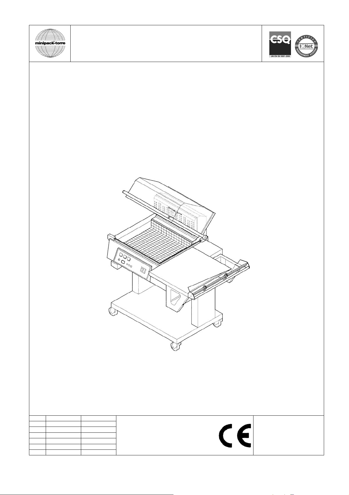
Synthesis
IT LEGGERE ATTENTAMENTE QUESTO LIBRETTO PRIMA DI USARE LA MACCHINA
EN BEFORE USING THE MACHINE PLEASE CAREFULLY READ THE INSTRUCTIONS
DE LESEN SIE SICH DIE BEDIENUNGSANLEITUNG BITTE GENAU DURCH, BEVOR SIE DIE MASCHINE BENUTZEN
FR NOUS VOUS PRIONS DE BIEN LIRE LE MANUEL D’INSTRUCTIONS AVANT D’UTILISER LA MACHINE
ES LEER ATENTAMENTE ESTE MANUAL ANTES DE USAR LA MÁQUINA
PT ANTES DE USAR A MÁQUINA LER CUIDADOSAMENTE ESTE LIVRETE
EL ∆ΙΑΒΑΣΤΕ ΜΕ ΠΡΟΣΟΧΗ ΤΙΣ ΠΑΡΑΚΑΤΩ Ο∆ΗΓΙΕΣ ΧΡΗΣΕΩΣ ΠΡΙΝ ΧΡΗΣΙΜΟΠΟΙΗΣΕΤΕ ΤΗ ΣΥΣΚΕΥΗ
IT
Italiano Pagina 01
EN
English Page 09
DE
Deutsch Seite 17
FR
Français Page 25
ES
Español Página 33
PT
Português Página 41
EL
Ελληνικά Σελίδα 49
DOC. N. FM111006
REV. 03
ED. 10.2013

ISTRUZIONI ORIGINALI
Indice IT
Capitolo 1. Introduzione
1.1. Prefazione Pagina 02
1.2. Prestazioni della macchina confezionatrice Pagina 02
1.3. Dati tecnici della macchina Pagina 02
Capitolo 2. Installazione della macchina
2.1. Trasporto e posizionamento Pagina 03
2.2. Condizioni ambientali Pagina 03
2.3. Collegamento elettrico Pagina 03
Capitolo 3. Regolazione ed approntamento macchina
3.1. Regolazione Pagina 04
3.2. Inserimento bobina film Pagina 05
3.3. Posizionamento del piatto retinato Pagina 05
3.4. Regolazione supporto bobina e piatto di confezionamento Pagina 05
3.5. Esecuzione 1ª saldatura film Pagina 05
3.6. Introduzione dell’oggetto da confezionare Pagina 05
3.7. Confezionamento Pagina 05
Capitolo 4. Limitazioni e condizioni d’uso della macchina
4.1. Dimensioni max. della confezione Pagina 05
4.2. Ciò che non si deve confezionare Pagina 05
Capitolo 5. Caratteristiche del film
5.1. Films da adoperare Pagina 06
5.2. Calcolo della fascia A Pagina 06
Capitolo 6. Norme di sicurezza
6.1. Avvertimenti Pagina 06
Capitolo 7. Manutenzione ordinaria
7.1. Cautele per interventi di manutenzione ordinaria Pagina 06
7.2. Pulizia lama saldante Pagina 07
7.3. Rimozione di sfridi di film plastico e vari Pagina 07
7.4. Pulizia della macchina Pagina 07
7.5. Cambio teflon e gomma Pagina 07
7.6. Cambio lama saldante Pagina 07
7.7. Schema elettrico Pagina 07
7.8. Particolari di ricambio Pagina 08
7.9. Smontaggio, demolizione e smaltimento residui Pagina 08
Capitolo 8. Garanzia
8.1. Certificato di garanzia Pagina 08
8.2. Condizioni di garanzia Pagina 08
Dichiarazione CE di conformità Pagina 57
1

Capitolo 1. Introduzione IT
1.1. Prefazione
Il presente manuale é redatto nel rispetto della norma UNI 10893 del Luglio 2000. É rivolto a tutti gli utilizzatori, al fine di
consentire un corretto uso della macchina. Consigliamo di conservarlo vicino ad essa, in un luogo facilmente accessibile
e noto a tutti gli utilizzatori. Questo manuale é parte integrante della macchina ai fini della sicurezza. Per migliorare la
comprensione precisiamo di seguito i simboli utilizzati.
ATTENZIONE
Norme antinfortunistiche per l’operatore. Tale avvertimento indica la presenza di pericoli che
possono causare lesioni a chi sta operando sulla macchina.
ATTENZIONE:
Organi caldi. Indica il pericolo di ustioni con rischio di infortunio, anche grave, per la persona
esposta.
AVVERTENZA:
Indica la possibilità di arrecare danno alla macchina e/o ai suoi componenti.
Tutti i diritti di riproduzione del presente manuale sono riservati alla ditta costruttrice. La riproduzione, anche parziale, è
vietata a termini di legge. Le descrizioni e le illustrazioni presenti in questo manuale non sono impegnative, di
conseguenza la ditta costruttrice si riserva il diritto di apportare in qualsiasi momento tutte le modifiche che riterrà
opportune. Il presente manuale non può essere ceduto in visione a terzi senza autorizzazione scritta della ditta
costruttrice. La macchina deve essere utilizzata solo per soddisfare le esigenze per cui è stata concepita, ogni altro uso
è da considerarsi “uso improprio”, quindi pericoloso.
Prima di compiere qualsiasi operazione sulla macchina è obbligatorio leggere attentamente tutte le istruzioni del
presente manuale, al fine di evitare possibili danneggiamenti alla macchina stessa, alle persone ed alle cose.
Non è consentito operare in caso di dubbi sulla corretta interpretazione delle istruzioni.
Interpellare il fabbricante per ottenere i necessari chiarimenti.
La macchina non è destinata a essere usata da persone (bambini compresi) le cui capacità fisiche, sensoriali o mentali
siano ridotte, oppure con mancanza di esperienza o di conoscenza, a meno che esse abbiano potuto beneficiare,
attraverso l’intermediazione di una persona responsabile della loro sicurezza, di una sorveglianza o di istruzioni
riguardanti l’uso dell’apparecchio.
I bambini devono essere sorvegliati per sincerarsi che non giochino con la macchina.
Al momento della consegna verificare che la macchina sia completa in tutte le sue parti.
Eventuali anomalie dovranno essere presentate immediatamente al fornitore.
La ditta costruttrice declina ogni responsabilità per uso improprio della macchina e/o per danni causati in seguito ad
operazioni non contemplate in questo manuale.
1.2. Prestazioni della macchina confezionatrice
Avete acquistato una macchina dalle caratteristiche e prestazioni eccezionali e Vi ringraziamo per la preferenza
accordataci. Il sistema di confezionamento é unico nel suo genere e si é affermato nel mondo con la presenza di oltre
150000 macchine operanti nel campo dell’imballaggio e del confezionamento.
La validità del concetto tecnologico, oltre che la qualità dei componenti e dei materiali impiegati nel processo produttivo e
di collaudo, sono la migliore garanzia di un buon funzionamento e di affidabilità nel tempo.
La macchina può essere utilizzata per saldare e termoretrarre il film contemporaneamente, oppure semplicemente per
saldarlo, grazie al suo particolare circuito di funzionamento. In quest’ultimo caso é possibile chiudere l’oggetto in
sacchetti flosci senza termoretrazione.
1.3. Dati tecnici della macchina
Peso e dimensioni dell’imballo
a = mm1350 b = mm 960 c = mm820 Peso = Kg134 (figura 1.3.A pag.58).
Peso e dimensioni della macchina
a = mm1280 b = mm780 c = mm1400 Peso = Kg100 (figura 1.3.B pag.58).
Produzione massima
300 confezioni/ora.
:
2
Capitolo 2. Installazione della macchina IT
2.1. Trasporto e posizionamento
Nel trasporto e nel posizionamento della macchina si raccomanda di manovrare con molta cautela!
Nella movimentazione della macchina utilizzare guanti di protezione
Tagliare con le forbici la reggia (avendo cura di proteggersi gli occhi con degli occhiali) e sfilare il cartone (figura
Togliere la scatola contenente il carrello (figura 2.1.B pag.58).
Svitare le 4 viti di fissaggio (B) al pallet, riportando all’interno della macchina le 4 piastrine (C) (figura 2.1.B pag.58).
Assemblare il carrello (figura 2.1.C pag.58).
Sollevare la macchina e collocarla sul carrello facendo attenzione che i 4 piedini siano ben inseriti nei loro
2.2. Condizioni ambientali
Posizionare la macchina accertandosi che sia livellata sul pavimento, in un ambiente adatto, privo di umidità,
Lasciare uno spazio minimo di 0,5m attorno alla macchina, per non ostruire le prese d’aria
Bloccare la macchina, una volta ottenuto il corretto posizionamento, agendo sul freno delle ruote.
Condizioni consentite negli ambienti in cui é collocata la macchina:
Temperatura da + 5°C a + 40°C
Umidità relativa da 30% a 90% senza condensazione.
L’illuminazione del locale di utilizzo deve essere conforme alle leggi vigenti nel paese in cui è installata la macchina e
deve comunque essere uniforme e garantire una buona visibilità, per salvaguardare la sicurezza e la salute
dell’operatore.
GRADO DI PROTEZIONE DELLA MACCHINA = IP20
IL RUMORE AEREO PRODOTTO DALLA MACCHINA È INFERIORE A 70 dB(A)
2.3. Collegamento elettrico
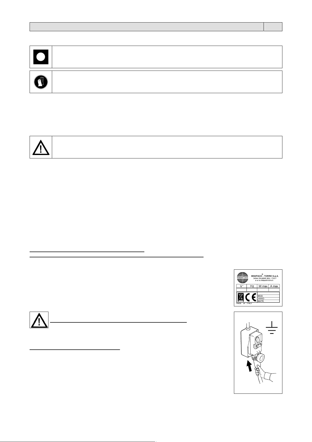
Tensione (V): vedere dati targhetta
Frequenza (Hz): vedere dati targhetta
Potenza massima assorbita (W): vedere dati targhetta
Corrente massima assorbita (A): vedere dati targhetta
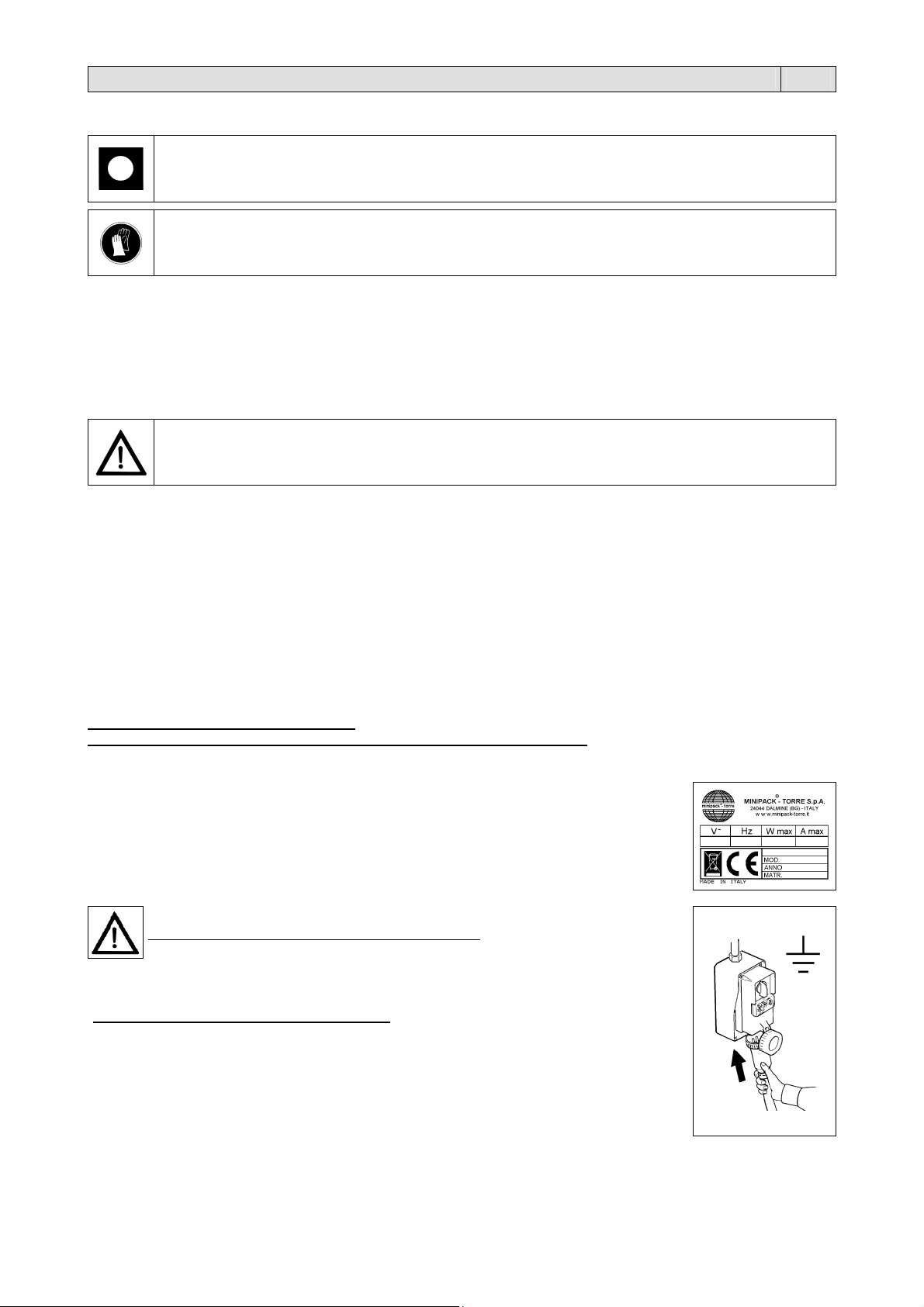
N.B.: per qualsiasi comunicazione con il costruttore, citare sempre il modello della macchina e il
numero di matricola indicati sulla targhetta applicata nella parte posteriore della macchina.
2.1.A pag.58).
alloggiamenti. Liberare la campana superiore tagliando la cordina di ritegno.
SE SI TRASPORTA A MANO È NECESSARIO L’INTERVENTO DI 4 PERSONE.
Per sollevare la macchina fare presa sempre alle estremità e comunque mai tramite il supporto
bobina (5).
materiali infiammabili, gas, esplosivi. La macchina deve essere installata solamente su superfici lisci, orizzontali e
non infiammabili.
RISPETTARE LE NORME PER LA SICUREZZA SUL LAVORO!
Se la macchina non è dotata della spina di alimentazione utilizzare una spina adeguata ai valori
di tensione e amperaggio descritti nella targhetta dati e comunque conforme alle normative
vigenti nel paese d’installazione.
È OBBLIGATORIA LA MESSA A TERRA!
Prima di effettuare il collegamento elettrico assicuratevi che la tensione di rete corrisponda al
voltaggio indicato sulla targhetta applicata nella parte posteriore della macchina e che il contatto
di terra sia conforme alle norme di sicurezza vigenti. In caso di dubbi sulla tensione di rete
contattate l’ente locale distributore dell’energia elettrica.
Collegare la spina del cavo proveniente dal quadro elettrico della macchina in una presa di
corrente del circuito generale che sia facilmente raggiungibile dall’operatore.
3

Capitolo 3. Regolazione ed approntamento macchina IT
3.1. Regolazione
1 Interruttore generale
2 Pulsante “DECREMENTA”. Riduce i valori delle funzioni impostate
3 Pulsante “INCREMENTA”. Aumenta i valori delle funzioni impostate
A Spia temperatura
B Spia retrazione
C Spia saldatura
P Pulsante di selezione programmi
D Display. Visualizza le funzioni selezionate e i relativi dati di impostazione
S Pulsante di selezione variabili
(figura 3.1. pag.59).
CARATTERISTICHE SCHEDA ELETTRONICA
La macchina ha 6 programmi da selezionare.
N° PROGRAMMA CARATTERISTICHE PROGRAMMA
P1
P2
P3
P4
P5
P6
Il programma più completo è composto da 4 variabili modificabili (chiaramente non comparirà la variabile, qualora questa
non possa essere impostata,):
VARIABILE CAMPO CARATTERISTICHE CAMPO
1. Temperatura
2. Saldatura
3. Retrazione
4. Ritardo Retrazione
FASE 1 = ACCENSIONE DELLA MACCHINA
Ruotare l’interruttore generale 1 nella posizione 1.
Prima di usare la macchina attendere che arrivi alla temperatura impostata, segnalata dallo spegnimento della spia A Il
display D si accende e compare il n° di programma attivo
FASE 2 = SELEZIONE PROGRAMMI
Per selezionare il n° di programma premere il pulsante P.
FASE 3 = PROGRAMMAZIONE VARIABILI
Con il pulsante S si scorrono le variabili del programma scelto e con i pulsanti 2 e 3 si modificano i valori memorizzati.
Per convalidare le modifiche premere il pulsante S fino a far comparire sul display il n° di programma.
Il tempo di ritardo ventola dopo la saldatura é una variabile modificabile che non ha un led associato e pertanto viene
indicato con una “r” sul display sinistro, mentre il display destro indica il tempo impostato.
Al termine di tutte le variabili programmabili, il display mostrerà nuovamente il codice del programma appena editato (es.
P1).
N.B.: se durante la programmazione viene premuto il fine corsa B1, l’apparecchio esce dalla programmazione e il
programma selezionato va immediatamente in esecuzione, mostrando di nuovo sul display il numero del programma.
FASE 4 = ESECUZIONE
Eseguite tutte le regolazioni, la macchina é pronta per procedere al confezionamento.
TABELLA INDICATIVA DELL’IMPOSTAZIONE CICLO MACCHINA
TEMPO DI RETRAZIONE TEMPO DI PAUSA TEMPERATURA (Campo)
6” 6” 50
5” 7” 60
4” 8” 70
3” 9” 80
2” 10” 90
In caso di “ANOMALIA ” sul display compaiono le seguenti sigle:
E 1 La macchina é stata accesa con la campana abbassata. Alzare la campana.
E 2 La macchina é stata accesa col pulsante S premuto.
Rilasciare il pulsante. Se permane la segnalazione di errore controllare il funzionamento del pulsante.
E 3 La temperatura di lavoro non è stata raggiunta nel tempo stabilito (10 min.).
Controllare che la sonda sia posizionata correttamente. Controllare la resistenza di riscaldamento. Controllare i
fusibili. Il ripristino avviene premendo il pulsante P.
E 4 La temperatura ha superato i 430°C oppure la sonda è interrotta.
Il ripristino avviene riavviando la macchina.
Solo saldatura
Saldatura + retrazione
Saldatura + retrazione ritardata a fine saldatura
Saldatura + retrazione
Saldatura + retrazione
Saldatura + retrazione
00 ÷ 99
0 ÷ 2.2
0.0 ÷ 9.9
0 ÷ 9
corrisponde a 200.....400°C (2°C per punto)-(valore medio 75)
valori espressi in secondi
valori espressi in secondi
valori espressi in decimi di secondo
.
4

Capitolo 3. Regolazione ed approntamento macchina IT
3.2. Inserimento bobina film
Inserire la bobina del film sul rullo (6) bloccandola mediante i coni centratori (7) (figura 3.2. pag.59).
Posizionare il rullo sul supporto bobina.
Passaggio attraverso i microforatori (8).
Passaggio del lembo inferiore del film sotto il piatto di confezionamento (9).
Passaggio del lembo superiore del film sopra il piatto di confezionamento (9).
3.3. Posizionamento del piatto retinato
Il piatto retinato (11) può essere sistemato a seconda dell’oggetto da confezionare.
Per il suo collocamentoo agire come segue (figura 3.3. pag.59):
tirare il piatto secondo le frecce
rimuovere il piatto dai riscontri
riposizionare il piatto sui riscontri all’altezza desiderata
N.B.: Per una buona confezione, il piatto retinato deve essere collocato in modo che la saldatura del film si trovi a metà
dell’altezza della confezione.
3.4. Regolazione supporto bobina e piatto di confezionamento
Il supporto bobina (5) e il piatto di confezionamento (9) devono essere regolati in funzione della larghezza (A)
dell’oggetto da confezionare, lasciando circa 1-2 cm di spazio tra l’oggetto ed il bordo di saldatura (figura 3.4. pag.59).
3.5. Esecuzione 1ª saldatura film
Per eseguire la 1ª saldatura portare il film come indicato in figura (figura 3.5. pag.59). Abbassare la maniglia della
campana con la mano sinistra e premere con una pressione di 10-15 Kg. La macchina entrerà automaticamente in
funzione e realizzerete la 1ª saldatura sul lato sinistro del film. Con la mano destra aiutate il distacco del film dalla lama
saldante. In questo modo il film é pronto per procedere al confezionamento.
3.6. Introduzione dell’oggetto da confezionare
Sollevare con la mano sinistra il bordo del film sul piatto di confezionamento.Introdurre con la mano destra il prodotto nel
film e farlo scorrere verso sinistra fino a depositarlo sul piatto retinato lasciando circa 1-2 cm di spazio tra il prodotto ed il
telaio interno di saldatura, in modo da permettere il passaggio dell’aria per la termoretrazione (figura 3.6. pag.59).
3.7. Confezionamento
Premendo sulla maniglia della campana con una pressione di circa 15 Kg., questa va ad appoggiarsi sulla lama saldante
(figura 3.7. pag.59). In questo modo avviene automaticamente la saldatura del film sui lati aperti (destro e di fronte).
Se avete selezionato la funzione “SALDATURA + RETRAZIONE” vedrete il film retrarsi attorno al prodotto, in questo
caso diminuite, leggermente, la pressione sulla maniglia della campana, in modo da permettere lo stacco del film dalla
zona di saldatura all’interno. Con la mano destra aiutate il distacco del film dalle lame saldanti verso l’esterno.
Capitolo 4. Limitazioni e condizioni d’uso della macchina IT
4.1. Dimensioni massime della confezione
a = mm 500 b = mm 380 c = mm 250 (figura 4.1. pag.59).
N.B.: le misure indicate nella tabella si riferiscono alla misura massima. della singola dimensione.
Per la misura massima della confezione (b x c), bisogna comunque fare riferimento al capitolo 5.2. dove si vede che la
somma di (b + c) é comunque uguale alla larghezza della bobina del film meno 100 mm.
4.2. Ció che non si deve confezionare
Per evitare di danneggiare in modo permanente la macchina, oltre che provocare rischi di infortuni all’operatore addetto,
é assolutamente vietato confezionare i seguenti tipi di prodotti:
prodotti bagnati e instabili
liquidi di qualsiasi tipo e densità in contenitori fragili
materiali infiammabili ed esplosivi
bombolette con gas a pressione o di qualsiasi tipo
polveri sciolte e volatili
materiali sciolti con dimensioni più’ piccole dei fori del piatto retinato.
eventuali materiali e prodotti non previsti che possano in qualche modo essere pericolosi per
l’utente e provocare danni alla macchina stessa
5
Capitolo 5. Caratteristiche del film IT
5.1. Films da adoperare
La macchina può lavorare con tutti i films termoretraibili e non, con spessore da 15 a 50 micron, sia di tipo tecnico,sia
alimentare. Per garantire i migliori risultati é consigliato l’utilizzo dei films da noi commercializzati.
Le speciali caratteristiche dei nostri films (anche con disegni e scritte personalizzate del cliente), danno garanzie di
affidabilità sia per la corrispondenza alle normative di legge vigenti, sia per la sicurezza di un ottimo funzionamento delle
nostre macchine.
Si raccomanda di consultare le schede tecniche e di sicurezza dei films utilizzati e di attenersi alle
prescrizioni descritte.
A = mm600 MAX D = mm250 MAX d = mm77 (figura 5.1. pag.60).
5.2. Calcolo della fascia A
Fascia A = b + c + 100mm (figura 5.2. pag.60).
Capitolo 6. Norme di sicurezza IT
6.1. Avvertimenti
NON PERMETTERE L’USO DELLA MACCHINA A PERSONALE NON ADDESTRATO!
Durante le fasi di lavoro porre attenzione a tutte le parti calde della macchina che possono
raggiungere temperature tali da provocare ustioni.
Durante il funzionamento della macchina è vietato fumare!
Non toccare la lama saldante (13) subito dopo la saldatura, oltrepassando con la mano la barriera di protezione
antinfortunistica (12). Possibilità di scottature dovute al residuo calore sulla lama saldante (13) (figura 6.1.A pag.60).
Non procedere nella saldatura nel caso di rottura della lama saldante (13). Provvedere immediatamente alla sua
sostituzione (figura 6.1.A pag.60).
Non toccare la paletta di chiusura polmone (16) durante la fase di riscaldo. Possibilità di scottature (figura 6.1.B
pag.60).
Assicurarsi che la bobina del film sia alloggiata correttamente nella sua sede (14) (figura 6.1.C pag.60).
Assicurarsi che i piedini di gomma (15) della macchina, siano alloggiati completamente nei fori di alloggiamento del
carrello (figura 6.1.D pag.60).
Quando non si utilizza la macchina lasciare sempre la campana superiore (19) aperta (figura 6.1.D
pag.60).
Capitolo 7. Manutenzione ordinaria IT
7.1. Cautele per interventi di manutenzione ordinaria
LA MANUTENZIONE ORDINARIA DEVE ESSERE EFFETTUATA DA PERSONALE QUALIFICATO
OPPORTUNAMENTE ISTRUITO.
Prima di effettuare le operazioni di manutenzione spegnere la macchina agendo sull’interruttore
generale, togliere la spina dalla presa di rete e attendere il raffreddamento della macchina.
Durante le operazioni di manutenzione si consiglia di utilizzare guanti di protezione.
6
Capitolo 7. Manutenzione ordinaria IT
7.2. Pulizia lama saldante
Rimuovere con un panno asciutto i residui di film che si possono depositare sulla lama saldante. Effettuare quest'
operazione subito dopo una saldatura, in modo che i residui, ancora caldi, possano essere asportati con facilità.
Lubrificare periodicamente la lama saldante con il grasso fornito in dotazione con la macchina (figura 7.2. pag.60).
7.3. Rimozione di sfridi di film plastico e vari
Prima di rimuovere eventuali residui di film depositati sulle parti calde della macchina (esempio sulla paletta apri
polmone calore), attendere che la macchina si sia adeguatamente raffreddata.
Nel caso di dover provvedere alla pulizia della campana inferiore, rimuovere il piatto retinato (11) ed asportare i pezzi
caduti all’interno (figura 7.3. pag.60).
7.4. Pulizia della macchina
Per la pulizia della campana superiore (19) pulire sia l’esterno che l’interno esclusivamente con
acqua e sapone (figura 7.4. pag.61).
Non utilizzare detergenti con solventi che potrebbero danneggiare la campana superiore (19) e
Per la pulizia della macchina utilizzare un panno inumidito con acqua.
É necessario pulire con maggiore frequenza sia l’esterno sia l’interno della macchina, se si trova in un ambiente
polveroso. Si consiglia soprattutto di aspirare la polvere che si deposita sui componenti elettrici interni.
7.5. Cambio teflon e gomma
É necessario sostituire i riscontri in teflon (17) con quelli di ricambio, quando sono troppo usurati, facendo molta
attenzione alla loro applicazione, che deve essere lineare e piana (figura 7.5. pag.61). Pulire con detergente la gomma
(18) prima dell’applicazione del nastro di teflon autoadesivo.
Se anche la gomma (18) risulta deteriorata provvedere alla sua sostituzione nel modo seguente:
1. togliere la gomma vecchia
2. pulire la sede che la contiene
3. mettere alcune gocce di colla nella sede stessa
4. inserire la nuova gomma in modo lineare
5. pulire la gomma con detergente
6. applicare il nastro di teflon autoadesivo
7.6. Cambio lama saldante
Seguire questa procedura, per sostituire la lama saldante (13) (figura 7.6. pag.61):
togliere tensione alla macchina
svitare le 3 viti (20)-(21)-(22)
togliere la lama saldante vecchia
pulire la sede e, se necessario, sostituire il teflon isolante (23) del morsetto centrale
inserire la lama saldante nuova partendo dal morsetto centrale e stringere la vite (21)
rifilare la lama saldante nuova a filo del foro dei pistoncini (24) e (25)
completare l’inserimento della lama saldante in tutta la sede
spingere a fondo il pistoncino posteriore (25) verso la lama saldante in modo che questa entri nel foro dello stesso e
stringere la vite (22)
spingere a fondo il pistoncino anteriore (24) verso la lama saldante in modo che questa entri nel foro dello stesso e
stringere la vite (20)
rifilare il teflon sporgente dal morsetto centrale
assicurarsi che la lama saldante sia posizionata bene ed in tensione.
7.7. Schema elettrico (figura 7.7. pagg.62/63).
B1 Finecorsa start ciclo M1/M2 Motore ventola
B2 Finecorsa avvolgitore M3 Motore avvolgitore
BT1 Termocoppia Q1 Interruttore generale
E1 Ventilatore raffreddamento Q2 Interruttore avvolgitore
ER1 Resistenza lama saldante QM1 Contattore lama saldante
ER2/3 Resistori QM2 Contattore resistori
F1 Fusibile linea 10.3X38 SK1 Scheda di comando
FU1 Fusibile scheda 5X20 T1 Trasformatore di taglio
FU3 Fusibile magnete 5X20 U1 Magnete di retrazione
FU4 Fusibile presa ausiliaria 5X20 V1 Filtro di rete anti disturbo
FU5 Fusibile motore 5X20 X1 Presa alimentazione avvolgitore
K1 Modulo di potenza X2 Spina alimentazione avvolgitore
ridurne la trasparenza.
ATTENZIONE!
Se il cavo di alimentazione è danneggiato, esso deve essere sostituito dal costruttore o dal suo servizio
assistenza tecnica, o comunque da una persona con qualifica similare, in modo da prevenire ogni rischio.
7
Capitolo 7. Manutenzione ordinaria IT
7.8. Particolari di ricambio
CODICE DENOMINAZIONE PARTICOLARE
S02A0404 Rivestimento teflon
FE385602 Lama saldante
FM350009 Gomma neoprene superiore
FM350006 Gomma neoprene inferiore
S0K00306 Morsetto porta lama completo
FE241052 (230V), FE241055 (115V), FE241053 (200V) Motore
FM130006 Piatto retinato
FM080028 Campana superiore
FM170002 Barra di torsione
S0K00604 Rotellina con cava completa
S0K00605 Rotellina con aghi completa
S02A0803 Tubo porta bobina completo
FM410001 Ventola
FM195066 Pannello lana di vetro
FE440612 (230V), FE440611 (115V), FE440612 (200V) Trasformatore
7.9. Smontaggio, demolizione e smaltimento residui
ATTENZIONE!
Le operazioni di smontaggio e demolizione devono essere affidate a personale specializzato a tali
attività e dotato delle competenze meccaniche ed elettriche necessarie a lavorare in condizioni di
sicurezza.
Procedere nel seguente modo:
1. scollegare la macchina dalla rete di alimentazione elettrica
2. smontare i componenti
Ciascun rifiuto deve essere trattato, smaltito o riciclato in base alla classificazione ed alle procedure previste
dalla legislazione vigente nel paese di installazione.
Il simbolo indica che questo prodotto NON deve essere trattato come rifiuto domestico.
Assicurando che il prodotto venga correttamente eliminato, si faciliterà la prevenzione di
potenziali conseguenze negative per l’ambiente e la salute dell’uomo, che potrebbero altrimenti
essere causate da un trattamento del rifiuto di questo prodotto non appropriato. Per informazioni
più dettagliate riguardo il riciclaggio di questo prodotto, contattare il venditore del prodotto, o in
alternativa il servizio di post vendita o l’apposito servizio di trattamento dei rifiuti..
Capitolo 8. Garanzia IT
8.1. Certificato di garanzia
La Garanzia ha una validità di 12 mesi dalla data di installazione, alle condizioni riportate sul libretto d’istruzioni.
Compilare il retro della cartolina in ogni sua parte, strappare lungo la linea e spedire.
8.2. Condizioni di garanzia
La garanzia è valida 12 mesi e decorre dalla data d’installazione della macchina. La garanzia consiste nella sostituzione
o riparazione gratuita di tutte quelle parti ritenute da noi difettose per anomalie di materiali. Le riparazioni o sostituzioni
avvengono normalmente presso la casa costruttrice con l’addebito all’acquirente delle spese di trasporto o manodopera.
Qualora le riparazioni o sostituzioni vengano eseguite presso la sede dell’acquirente, quest’ultimo sarà tenuto a pagare
le spese di viaggio, trasferta e manodopera. Le prestazioni di garanzia vengono eseguite esclusivamente a cura della
casa costruttrice o dal rivenditore autorizzato. Per avere diritto a prestazioni di garanzia inviare alla casa costruttrice od
al rivenditore autorizzato il pezzo difettoso, perché sia effettuata la riparazione o sostituzione. La riconsegna di tale
pezzo riparato o sostituito, rientrerà nell’adempimento delle operazioni di garanzia. La garanzia viene annullata:
1. per il mancato immediato invio postale del CERTIFICATO DI GARANZIA al momento dell’acquisto, debitamente
compilato e firmato entro 20 giorni.
2. per l’errata installazione, l’inadeguata alimentazione, negligenza d’uso e manomissione da parte di persone non autorizzate.
3. per modifiche effettuate sulla macchina senza il consenso scritto della casa.
4. qualora la macchina non sia più proprietà del primo acquirente
La casa costruttrice declina a termine di legge ogni responsabilità per danni a persone o cose, qualora venga
effettuata un’errata installazione o collegamento alla rete di alimentazione elettrica o esclusione della messa a
terra od in caso di manomissioni della macchina stessa. La casa costruttrice si riserva di approntare modifiche
e cambiamenti secondo esigenze tecniche e di funzionamento.
PER QUALUNQUE CONTROVERSIA LEGALE
IL FORO COMPETENTE È QUELLO DI BERGAMO (ITALIA).
8

TRANSLATION OF THE
ORIGINAL INSTRUCTIONS
Index EN
Chapter 1. Foreword
1.1. Preface Page 10
1.2. Performances of packaging machine Page 10
1.3. Technical data of the machine Page 10
Chapter 2. Machine installation
2.1. Transport and positioning Page 11
2.2. Environmental conditions Page 11
2.3. Electrical connections Page 11
Chapter 3. Machine adjustment and setting up
3.1. Adjustment Page 12
3.2. Film reel insertion Page 13
3.3. Reticulated plate installation Page 13
3.4. Reel support and packaging plate adjustment Page 13
3.5. Execution of 1^ film sealing Page 13
3.6. Introducing the object to be wrapped Page 13
3.7. Making up Page 13
Chapter 4. Limits and conditions in the use of machine
4.1. Max. packing sizes Page 13
4.2. Items which must not be packed Page 13
Chapter 5. Film features
5.1. Films to be used Page 14
5.2. Band A calculation Page 14
Chapter 6. Safety standards
6.1. Warnings Page 14
Chapter 7. Ordinary maintenance
7.1. Precautions for ordinary maintenance interventions Page 14
7.2. Sealing blade cleaning Page 15
7.3. Plastic film and other scrap removal Page 15
7.4. Machine cleaning Page 15
7.5. Rubber and teflon replacement Page 15
7.6. Changing the sealing blade Page 15
7.7. Wiring diagram Page 15
7.8. Spare parts Page 16
7.9. Disassembling, demolition and elimination of residuals Page 16
Chapter 8. Guarantee
8.1. Certificate of guarantee Page 16
8.2. Guarantee conditions Page 16
EC declaration of conformity Page 57
9

Chapter 1. Foreword EN
1.1. Preface
This manual has been drawn up in compliance with the UNI10893 standard dated July 2000. It is meant for all users in
order to enable them to use the machine correctly. Keep it in a place which can be easily accessed in the proximity of the
machine and which is known to all users. This manual is an integral part of the machine for safety reasons. We wish to
specify the symbols in use here below in order to improve their understanding.
ATTENTION:
Accident prevention rules for the operator. This warning indicates the presence of dangers which
can injure the person operating on the machine..
All reproduction rights of this manual are reserved to the manufacturer. Partial or complete reproduction is forbidden as
provided by the law. Descriptions and pictures provided in this manual are not binding. Therefore the manufacturer,
reserves the right to make any change considered necessary. This manual cannot be transferred for viewing to third
parties without authorisation in writing from the manufacturing company. The machine must be used only for the purpose
it was built for. Any other use shall be considered “improper” and therefore dangerous. Before carrying out any operation
on the machine it is compulsory to read carefully all instructions provided in this manual, in order to avoid possible
damage to the machine, to people and property.
Do not operate if in doubt about the correct interpretation of the instructions.
Contact the manufacturer in order to obtain the necessary explanation.
This machine is not intended for use by persons (including children) with reduced physical, sensory or mental
capabilities, or lack experience and knowledge, unless they have been given supervision or instruction concerning use of
the machine by a person responsible for their safety.
Children should be supervised to ensure that they do not play with the machine.
Upon delivery check that the machine is complete in all parts.
Possible faults shall be immediately reported to the manufacturer.
The manufacturing company declines any liability in case of machine improper use and/or in case of damage resulting
from operations carried out on the machine that are not mentioned in this manual.
1.2. Performances of packaging machine
You have bought a machine with outstanding features and performance and we thank you very much for your confidence
in choosing it. The system is unique in its kind and has achieved worldwide success with more than 150000 units
operating in the field of packaging and wrapping.
The technological concept underlining its design, as well as the components and materials used in the manufacturing
and testing process are the best assurance of proper operation and long-lasting liability.
Thanks to its particular operating circuit, it can be used both as a sealing and shrinking machine or as a plain sealing
machine (sealing only). In this case it is possible to pack the object in a soft bag without shrink-wrapping. The film used
in centerfolded execution can be micropunched or not when running through the micropunches of machine itself.
1.3. Technical data of the machine
Package weight and sizes
a = mm1350 b = mm960 c = mm820 Weight = Kg134 (figure 1.3.A page 58).
Machine weight and sizes
a = mm1280 b = mm780 c = mm1400 Weight = Kg100 (figure 1.3.B page 58).
Maximum production
300 packages/hour.
ATTENTION:
Hot members. It shows the danger of burning, thus involving the risk of a serious accident for the
exposed person.
WARNING:
It indicates the possibility of damaging the machine and/or its components..
10
Chapter 2. Machine installation EN
2.1. Transport and positioning
It is recommended to handle with great care during transport and positioning..
Use protection gloves while handling the machine.
Cut the strap with scissors (make sure you protect your eyes by wearing glasses) and withdraw the cardboard
Remove the cardboard containing the trolley (figure 2.1.B page 58).
Unscrew the 4 fastening screws (B) of the pallet, putting the 4 plates back inside the machine (C) (figure 2.1.B page
Assemble the trolley (figure 2.1.C page 58).
Lift the machine and place it on its trolley, paying attention that the 4 supports are properly inserted in their housings.
2.2. Environmental conditions
Place the machine level on the floor in a suitable environment free from humidity, gases, explosives, combustible
Leave a minimum space of 0,5m around the machine so that not to obstruct air inlets
Once the correct position is achieved, lock the machine by means of the wheel brakes.
Working environment conditions:
Temperature from + 5°C to + 40°C
Relative humidity from 30% to 90%, without condensation.
The lighting of the operation room shall comply with the laws in force in the country where the machine is installed.
However, it shall be uniform and allow good visibility in order to safeguard the operator’s safety and health.
MACHINE PROTECTION FACTOR = IP20
THE AIRBORNE NOISE MADE BY THE MACHINE IS LOWER THAN 70 dB(A)
2.3. Electrical connections
Voltage (V): see data on plate
Frequency (Hz): see data on plate
Maximum absorbed power (W): see data on plate
Maximum absorbed current (A): see data on plate
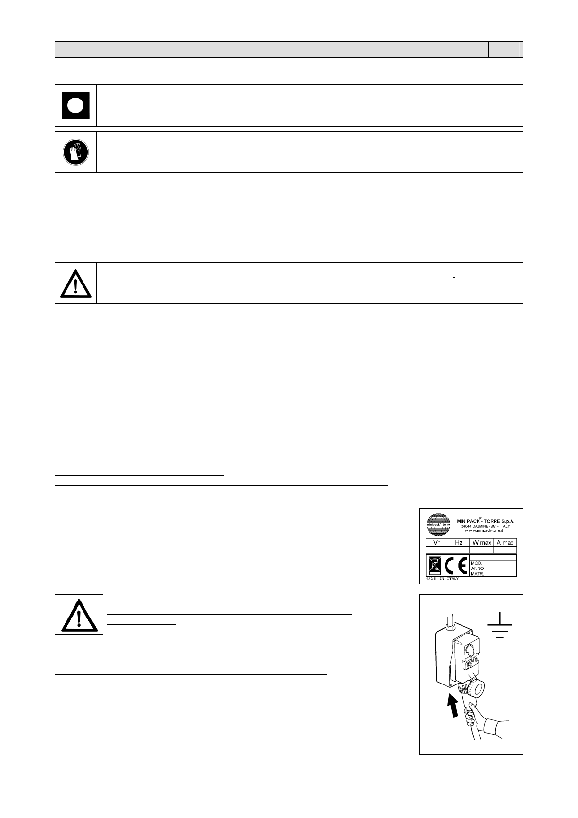
N.B.: when contacting the Manufacturer, always indicate the model and the serial number
specified on the plate on the rear part of the machine.
(figure 2.1.A page 58).
58).
Remove the upper hood by cutting the strings.
IF IT IS TRANSPORTED BY HAND, 4 PEOPLE ARE REQUIRED FOR ITS TRANSPORTATION.
When lifting the machine, always grip it by the ends and never by the reel support (5).
materials. The machine may only be installed on smooth, flat non-inflammable surfaces.
OBSERVE HEALTH AND SAFETY REGULATIONS!
If the machine is not equipped with the power supply plug, use a plug that is suitable for the
voltage and amperage values described by the rating plate and that can comply with the rules
in force in the installation country.
GROUNDING OF THE UNIT IS OBLIGATORY!
Before making electrical connections, make sure the mains voltage matches the one on the
plate on machine rear and that the ground contact complies with the safety rules in force.
In case of doubts about the mains voltage, contact the local power supply company.
Insert the plug on the cable from machine electrical cabinet in a mains power supply socket
that can be reached easily by the operator.
11

Chapter 3. Machine adjustment and setting up EN
3.1. Adjustment
1 Main switch
2 Button “DECREASE”. Reduces set function values
3 Button “INCREASE”. Increases set function values
A Temperature warning light
B Shrinking warning light
C Sealing warning light
P Programs selection button
D Display. Displays selected functions and relative settings
S Variables selection switch
(figure 3.1. page 59).
ELECTRONIC BOARD FEATURES
The machine is equipped with 6 selectionable programs:
PROGRAM NR. PROGRAM FEATURES
P1
P2
P3
P4
P5
P6
Each program is composed by 4 variables which can be modified (in case it is not possible to set one of them, such a
variable will obviously not appear on the display):
VARIABLE FIELD FIELD FEATURES
1. Temperature
2. Sealing
3. Shrinking
4. Shrinking delay
PHASE NR. 1 = SWITCHING THE MACHINE ON
Turn the main switch 1 into pos. 1. Before using the machine, wait until the adjusting temperature is reached. This is
signalled by the extinction of the warning light A The display D turns on and the number of the currently selected program
will appear.
PHASE NR. 2 = PROGRAMS SELECTION
Push button P to select the number of the program.
PHASE NR. 3 = VARIABLES PROGRAMMING
Through button S it is possible to look through the variables of the selected program, while through buttons 2 and 3 the
memorized values can be modified. To validate modifications, press button S until the number of the program appears on
the display.
The fan delay time after sealing can be modified; there is not a led indicating this variable which is shown with an “r” on
the left display, while the right one shows the time which has been set. At the end of all variables to be adjusted, the
display will show the code of the program just chosen (for example P1).
N.B.: In case during programming the B1 limit switch is being pressed, the unit quits the scheduling, the selected
program is executed and the display shows the number of the program.
PHASE NR. 4 = PERFORMANCE
Once all adjustments have been made, the machine is ready to start working.
APPROXIMATE TABLE OF MACHINE CICLE ADJUSTEMENT
SHRINKING TIME PAUSE TIME TEMPERATURE (Field)
6” 6” 50
5” 7” 60
4” 8” 70
3” 9” 80
2” 10” 90
In case of “ANOMALY” the display will show as follows:
E 1 Machine has been switched on when the hood was lowered. Lift the hood up.
E 2 Machine has been switched on when the S button was pressed. Release the button. In case the error signalling
still persists, check the correct functioning of the button.
E 3 Working temperature hasn’t been reached in the set time (10 min.). Check the correct positioning of the feeler.
Check heater and fuses. Reset through P button.
E 4 Temperature is higher than 430°C or feeler has been interrupted. Switch the machine on to reset.
Sealing only
Sealing + shrinking
Sealing + delayed shrinking to sealing end
Sealing + shrinking
Sealing + shrinking
Sealing + shrinking
00 ÷ 99
0 ÷ 2.2
0.0 ÷ 9.9
0 ÷ 9
corresponds to 200.....400°C (2°C each point)-(medium value 75)
values expressed in seconds
values expressed in seconds
tenth-seconds values
12

Chapter 3. Machine adjustment and setting up EN
3.2. Film reel insertion
Insert the reel of film on the roller (6) and block it through the centering cones (7) (figure 3.2. page 59).
Position the roller on the film reel support.
Run through the micropunches (8).
Run the film lower layer under the packaging plate (9).
Run the film upper layer over the packaging plate (9).
3.3. Reticulated plate installation
The reticulated plate (11) can be placed according to the height of the product to pack.
To position it follow this procedure (figure 3.3. page 59):
pull the reticulated plate in direction of the arrows
remove it from the stops
position the plate on the stops at the required height
N.B.: For a proper packaging the reticulated plate must be positioned so that film sealing is at the half of the package
height.
3.4. Reel support and packaging plate adjustment
The reel support (5) and the packaging plate (9) must be adjusted according to the width of the article to be packaged,
leaving a space of about 1-2 cm between the article and the sealing edge (figure 3.4. page 59).
3.5. Execution of 1^ film sealing
Place film as shown in the picture to carry out the first seal (figure 3.5. page 59). Lower the handle of the cover with your
left hand and make a pressure of 10-15 Kg. Machine will automatically operate and the first seal will be carried out on the
side of the film. With the right hand detach the film from the sealing blade. Film is now ready to carry out wrapping.
3.6. Introducing the object to be wrapped
With the left hand slide on the packaging plate the quantity of film necessary to contain the product to be packed.
Introduce the product into the bag using the right hand and make it slide to the left until it is laid on the screen leaving a
little space of about 1-2 cm to allow the passage of air for shrinkwrapping (figure 3.6. page 59).
3.7. Making up
By pushing the cover handle with a pressure of 10-15 Kg. the cover rests on the sealing blade (figure 3.7. page 59); by
pinching the film, it is automatically sealed on the open sides (right and front). In case you have selected the function
“SEALING +SHRINKWRAPPING” you will see the film shrink onto the product. Slightly decrease the pressure on the
cover handle to allow film detach from the sealing area on the inside. With the right and detach the film from the sealing
blade towards the outside.
Chapter 4. Limits and conditions in the use of machine EN
4.1. Max. packing sizes
a = mm 500 b = mm 380 c = mm 250 (figure 4.1. page 59).
N.B.: max. dimensions shown on above scheme are referring to the max. dimension of the single package.
Refer to chapter 5.2. to get max. dimension of package (b x c); the addition of (b + c) is equal to film roll width 100 mm.
4.2. Items which must not be packed
The below listed products must absolutely not be wrapped to avoid damages to the machine and serious injuries to the
operator in charge:
Wet and unstable products
Liquids of any kind and density in fragile containers
Flammable and explosive materials
Pressurised gas cylinder of any kind
Bulk and volatile powders
Bulk materials with grain size smaller than the holes of the reticulated plate
Any materials and products not listed but which might harm operator and cause damages to
the machine.
13

Chapter 5. Film features EN
5.1. . Films to be used
The machine can work with all thermoshrinkable and non-thermoshrinkable films, from 15 to 50 microns in thickness, of a
technical and food type. To guarantee the best results, it is recommended to use the films marketed by us.
The special features of our films (which may be customised with drawings and text) assure their outstanding reliability,
with regard both to compliance with laws in force and to an excellent machine performance.
It is recommended to refer to the technical and safety sheets of the films in use and to observe the
corresponding instructions!
A = mm600 MAX D = mm250 MAX d = mm77 (figure 5.1. page 60).
5.2. Band A calculation
Band A = b + c + 100mm (figure 5.2. page 60).
Chapter 6. Safety standards EN
6.1. Warnings
THE MACHINE CAN NOT BE USED BY UNTRAINED PERSONNEL!
During the work phases pay attention to all hot parts of the machine. The temperature they can
reach is so high that it can cause burns.
It is forbidden to smoke when the machine is working!
Do not touch the sealing blade (13) soon after sealing by reaching beyond the safety guard (12). Danger of burns
due to residual heat on the sealing blade (figure 6.1.A page 60).
Do not keep on sealing in case the sealing blade breaks (13). Replace it at once (figure 6.1.A page 60).
Do not touch the chamber closing flap (16) during warm-up function. Danger of burns (figure 6.1.B page 60).
Make sure the film reel is properly lodged (14) (figure 6.1.C page 60).
Make sure the rubber feet (15) of machine are lodged in the holes of the wheeled stand (figure 6.1.D page 60).
Every time you turn the machine off, it is recomended to leave the upper hood (19) open (figure
6.1.D page 60).
Chapter 7. Ordinary maintenance EN
7.1. Precautions for ordinary maintenance interventions
ORDINARY MAINTENANCE, MUST BE EXECUTED BY QUALIFIED STAFF APPROPRIATELY TRAINED.
Before proceeding to maintenance, switch the machine off and disconnect it by operating on the
master switch and wait for the machine to cool down
It is recommended to use protection gloves during maintenance operations!
14
Chapter 7. Ordinary maintenance EN
7.2. Sealing blade cleaning
Using a dry cloth, wipe off the residues clinging to the sealing blade: do this at once after sealing since they are
easier to remove when still warm.
Periodically lubrificate the sealing blade with the grease supplied with the machine (figure 7.2. page 60).
7.3. Plastic film and other scrap removal
Wait for the machine to cool down completely before removing any scraps stuck to the hot parts of the machine (e.g., on
the flaps of the heat chamber). If the lower cover requires cleaning (where the fan is installed), remove the reticulated
plate (11) and take out any pieces that may have fallen inside (figure 7.3. page 60).
7.4. Machine cleaning
To clean the upper hood (19), clean both the outer and the inner side with water and soap only
(figure 7.4. page 61).
Do not use any detergents with solvents which could damage the upper hood (19) and reduce the
Use a cloth moistened with water for the cleaning of the machine .
If the machine works in a dusty environment it is necessary to clean it more frequently inside as well as outside. It is
transparency.
especially recommended to vacuum-clean the dust which settles on the interior electrical components. To open the
switch box again remove the 4 fastening screws.
7.5. Rubber and teflon replacement
When the Teflon-strikers (17) are worn out, replace them with spare parts, paying attention that the application is linear
and even (figure 7.5. page 61). Before applying the Teflon self-adhesive strip clean the rubber part (18) with a detergent.
If also the rubber (18) is damaged, replace it as follows:
1. remove the old rubber
2. clean its housing
3. apply some drops of glue in the housing
4. insert the new rubber in a linear way
5. clean the rubber with a detergent
6. apply the self-adhesive Teflon-strip.
7.6. Changing the sealing blade
To replace the sealing blade (13) follow this procedure (figure 7.6. page 61):
disconnect power to the machine
unscrew the three screws (20), (21), (22)
remove the old sealing blade
clean the housing and if necessary replace the insulating teflon (23) of the central clamp
insert the new sealing blade starting from the central clamp and tighten the screw (21)
trim the new sealing blade according to the holes of the pistons (24) and (25)
complete the insertion if the sealing blade in the whole housing
push the rear piston completely onwards (25) towards the sealing blade to make it enter the hole of the piston itself
and then tighten screw (22)
push the front piston (24) completely onwards towards the sealing blade to make it enter the hole of the piston itself
and then tighten screw (20)
trim the teflon projecting from the central clamp
make sure that the sealing blade is well positioned and in tension
ATTENTION!
If the supply cord is damaged, it must be replaced by the manufacturer, its service agent or similarly
qualified persons in order to avoid a hazard.
7.7. Wiring diagram (figure 7.7. pages 62/63).
B1 Cycle start limit switch M1/M2 Fan motor
B2 Rewinder limit switch M3 Rewinder motor
BT1 Thermocouple Q1 Main switch
E1 Cooling fan Q2 Rewinder switch
ER1 Sealing blade heater QM1 Sealing blade contactor
ER2/3 Oven resistors QM2 Heaters contactor
F1 Line fuse 10.3X38 SK1 Control board
FU1 Board fuse 5X20 T1 Cutting transformer
FU3 Magnet fuse 5X20 U1 Shrinking magnet
FU4 Auxiliary plug fuse 5X20 V1 Antinoise filter
FU5 Motor fuse 5X20 X1 Rewinder power supply socket
K1 Electronic control board X2 Rewinder power supply plug
15

Chapter 7. Ordinary maintenance EN
7.8. Spare parts
CODE ITEM DESCRIPTION
S02A0404 Teflon liner
FE385602 Sealing blade
FM350009 Upper neoprene rubber
FM350006 Lower neoprene rubber
S0K00306 Blade holder complete clamp
FE241052 (230V), FE241055 (115V), FE241053 (200V) Motor
FM130006 Reticulated plate
FM080028 Upper hood
FM170002 Torsion bar
S0K00604 Complete slotted microperforator
S0K00605 Complete needles microperforator
S02A0803 Roll holder complete tube
FM410001 Fan
FM195066 Glass wool panel
FE440612 (230V), FE440611 (115V), FE440612 (200V) Transformer
7.9. Disassembling, demolition and elimination of residuals
ATTENTION!
All operations about disassembling and demolition must be done by qualified personnel with
mechanical and electrical expertise required to work in security conditions.
Proceed as follows:
1. disconnect machine from power mains
2. disassemble components
All wastes must be treated, eliminated or recycled according to their classification and to the procedures in
force established by the laws in force in the country the equipment has been installed.
The symbol indicates that this product shall NOT be treated as household waste.
By assuring that the product will be properly disposed of, you will facilitate the prevention of
potential negative effects for the environment and the man’s health, which might be otherwise
caused by the improper waste treatment of this product.
For more detailed information about the recycling of this product, please contact the product seller
or, as an alternative, the after-sales service or the corresponding waste treatment service.
Chapter 8. Guarantee EN
8.1. Certificate of guarantee
The guarantee runs for 12 months after the installation date under the conditions set forth on the instruction manual. Fill
in the card with all data requested,tear out along the perforations and send in.
8.2. Guarantee conditions
The guarantee runs for 12 months and goes into force on the installation date of the machine. The guarantee covers free
replacement or repair of any parts due to defects arising from faulty material. The repairs or replacement are usually
carried out at the manufactures, with transport or workmanship at buyer’s charge. If the repair or replacement is carried
out at the buyer’s place, he shall bear the travelling, transfer and workmanship charges. Work under guarantee can be
carried out exclusively by the manufacturer or by the authorised dealer. In order to be entitled to repairs under the
guarantee, the faulty part must be sent for repair or replacement to the manufacturer or his authorised dealer. The return
of such repaired or replaced part will be considered to be the performance of the guarantee.
The guarantee is voided:
1. in case of failure to mail the CERTIFICATE OF GUARANTEE, duly filled in and signed, with in 20 days after the date of purchase.
2. in case of inappropriate installation, power supply, misuse and mishandling by unauthorised persons.
3. in case of changes made to the machine without prior agreement in writing by the manufacturers.
4. if the machine is no longer the property of the first buyer.
The manufacturer decline any responsibility for damage to persons or things in case of inappropriate
installation or connection to the power mains or omission of connection to earth or in case of any mishandling
of the machine. The manufacturer undertake to carry out any variations and changes made necessary by
technical and operating requirements.
IN THE EVENT OF DISPUTES THE COURT OF BERGAMO (ITALY)
SHALL HAVE SOLE JURISDICTION.
16

ÜBERSETZUNG DER ORIGINAL-
ANLEITUNG
Inhaltsverzeichnis DE
Kapitel 1. Einleitung
1.1. Vorwort Seite 18
1.2. Leistungen der Verpackungsmachine Seite 18
1.3. Technische Angaben der Maschine Seite 18
Kapitel 2. Aufstellung der Maschine
2.1. Beförderung und Positionierung Seite 19
2.2. Umweltbedingungen Seite 19
2.3. Elektrischer Anschluß Seite 19
Kapitel 3. Regelung und Bereitstellung der Maschine
3.1. Regulierung Seite 20
3.2. Einlegung der Folienspule Seite 21
3.3. Positionieren des Haltegitters Seite 21
3.4. Die regulierung des spulenträgers und des Verpackungsflachstabes Seite 21
3.5. Durchführung der ersten Schweissung Seite 21
3.6. Einführen des Verpackungsgutes Seite 21
3.7. Verpacken Seite 21
Kapitel 4. Gebrauchsbeschränkungen und Gebrauchsbedingungen der Maschine
4.1. Maximaldimensionen der Packung Seite 21
4.2. Was nicht verpackt werden darf Seite 21
Kapitel 5. Folieneingeschaften
5.1. Die zu verwendenden Folie Seite 22
5.2. Wie der A-streifen berechnet werden muss Seite 22
Kapitel 6. Sicherheitsmassnahmen
6.1. Warnungen Seite 22
Kapitel 7. Wartung der Maschine
7.1. Maßnahmen, die getroffen werden müssen, bevor Wartungsarbeiten durchgefürt werden Seite 22
7.2. Reinigung der schweißenden Klinge Seite 23
7.3. Entfernung von abfällen des plastischen Folien und anderer Art Seite 23
7.4. Reinigung der Maschine Seite 23
7.5. Wie Teflon und Gummi ersetzt werden müssen Seite 23
7.6. Auswechseln der Schweißklinge Seite 23
7.7. Schaltbild Seite 23
7.8. Ersatzteile Seite 24
7.9. Demontage, abbau und entsorgung der rückstände Seite 24
Kapitel 8. Garantiezeit
8.1. Garantieschein Seite 24
8.2. Garantiebedingungen Seite 24
EG Konformitätserklärung Seite 57
17

Kapitel 1. Einleitung DE
1.1. Vorwort
Das vorliegende Handbuch wurde gemäß den Norm UNI 10893 von Juli 2000 abgefasst. Es richtet sich an alle Benutzer
und dient zur korrekten Bedienung der Maschine. Bewahren Sie es an einem leicht zugänglichen Ort in der Nähe der
Maschine auf, der allen Benutzern bekannt ist. Das vorliegende Handbuch ist hinsichtlich der Sicherheit, ein wesentlicher
Teil der Maschine. Zur besseren Verständlichkeit werden die verwendeten Symbole erläutert.
ACHTUNG:
Unfallschutzvorschriften für den Bediener. Diese Warnung weist auf bestehende Gefahren hin,
durch die eine Verletzungsgefahr für den Bediener besteht.
Alle Rechte des vorliegenden Handbuchs sind dem Hersteller vorbehalten. Die Vervielfältigung, auch auszugsweise, ist
gesetzlich verboten. Die in diesem Handbuch enthaltenen Beschreibungen und Abbildungen sind unverbindlich. Der
Hersteller behält sich vor, jederzeit Änderungen vorzunehmen, die er als notwendig erachtet. Dieses Handbuch darf
ohne schriftliche Genehmigung des Herstellers nicht zur Einsicht an Dritte ausgehändigt werden. Die Maschine darf nur
für den vorgesehenen Anwendungszweck eingesetzt werden; jede andere Anwendung ist als „unsachgemäß“ und somit
als gefährlich anzusehen.
Vor Bedienung der Maschine müssen sorgfältig alle Hinweise in diesem Handbuch durchgelesen werden, um potentielle
Schäden an Maschine, Personen oder Gegenständen zu vermeiden.
Bei Zweifeln an der richtigen Auslegung der Hinweise darf die Maschine nicht betrieben werden.
Bitte wenden Sie sich für die notwendigen Erläuterungen an den Hersteller.
Die Maschine ist nicht dazu bestimmt, von Personen (einschließlich Kindern) angewandt zu werden, deren körperliche,
mentale oder Sinnesfähigkeiten eingeschränkt sind, oder die zu wenig Erfahrung oder Kenntnisse haben, außer wenn
sie durch eine Person, die für ihre Sicherheit verantwortlich ist, überwacht werden oder von dieser Anweisungen über
den Gebrauch des Geräts erhalten.
Kinder müssen ständig überwacht werden, um sicherzustellen, dass sie nicht mit der Maschine spielen.
Prüfen Sie bei der Auslieferung der Maschine, ob sie in allen ihren Teilen vollständig ist.
Eventuelle Auffälligkeiten müssen sofort dem Lieferanten mitgeteilt werden.
Der Hersteller lehnt jede Haftung für unsachgemäße Anwendung der Maschine und/oder Schäden ab, die auf
Tätigkeiten zurückzuführen sind, die nicht in diesem Handbuch vorgesehen sind.
1.2. Leistungen der Verpackungsmachine
Sie haben ein äußerst leistungsfähiges Gerät mit außergewöhnlichen Eigenschaften erworben, und wir danken Ihnen für
die getroffene Wahl.Das Verpackungssystem ist einzing in seiner Art, seine Stellung wird durch die Anzahl von über
150000 weltweit verkauften Geräten bestätigt. Der Wert des technologischen Konzepts, die Qualität der Einzelteile und
der in der Fertigung verwendeten Werkstoffe sowie der Endkontrolle sind die beste Garantie für ein zuverläßiges
Funktionieren über einen langen Zeitraum.
Das Gerät kann für das gleichzeitige Schrumpfen und Schweißen der Folien verwendet werden, es kann dank seines
Funktionsprinzips aber auch nur zum Schweißen eingesetzt werden. In diesem Fall ist es möglich, die
Verpackungsobjekte in lose, nicht geschrumpfte Säcke einzuschweißen.
1.3. Technische Angaben der Maschine
Gewicht und Größen der Verpackung
a = mm1350 b = mm960 c = mm820 Gewicht = Kg134 (Abbildung 1.3.A Seite 58).
Gewicht und Größen der Maschine
a = mm1280 b = mm780 c = mm1400 Gewicht = Kg100 (Abbildung 1.3.B Seite 58).
Höchstproduktion
300 Verpackungen pro Stunde
ACHTUNG:
Heiße Maschinenteile. Zeigt eine für die ausgesetzte Person auch schwerwiegende
Verbrennungsgefahr durch heiße Maschinenteile an.
VOSICHT:
Weist auf die Gefahr hin, die Maschine bzw. deren Komponenten zu beschädigen.
18
Kapitel 2. Aufstellung der Maschine DE
A
2.1. Beförderung und Positionierung
Bei der Beförderung und Positionierung der Maschine lassen Sie die größte Vorsicht walten
Beim Umstellen der Maschine Schutzhandschuhe tragen.
Schneiden Sie das Band mit Schere (schützen Sie Ihre Augen mit Brillen) und ziehen Sie den Karton ab (Abbildung
Den Schlitten aus der Schachtel herausnehmen (Abbildung 2.1.B Seite 58).
Die 4 Feststellschrauben (B) herausziehen und die 4 Schweißlappen (C) innerhalb der Maschine einlegen
Den Schlitten montieren (Abbildung 2.1.C Seite 58).
Die Maschine abheben und sie auf den Schlitten positionieren. Achten Sie darauf, daß die 4 Füße in ihren eigenen
2.2. Umweltbedingungen
Das Gerät muss eben auf dem Boden aufgestellt werden, sowie in einer geeigneten Umgebung, die trocken ist und
Um die Maschine herum müssen mindestens 0,5m frei gelassen werden, damit die Lüfteröffnungen nicht verdeckt
Sobald die Maschine ordnungsgemäß aufgestellt ist, wird sie mithilfe der Radbremse festgestellt.
Zulässige Umgebungsbedingungen am Aufstellungsort der Maschine:
Temperaturen zwischen + 5°C und + 40°C
Relative Luftfeuchtigkeit zwischen 30 % und 90 %, ohne Kondensation.
Die Beleuchtung des Raums, in dem die Maschine benutzt wird, muss den Gesetzen entsprechen, die im Einbauland der
Maschine gelten und auf jeden Fall gleichmäßig sein und eine gute Sichtbarkeit gewährleisten, um die Sicherheit und die
Gesundheit des Bedieners zu schützen.
SCHUTZKLASSE DER MASCHINE = IP20
DAS VON DER MASCHINE ERZEUGTE LUFTGERÄUSCH LIEGT UNTER 70 dB(A)
2.3. Elektrischer Anschluß
Spannung (V): siehe Typenschild
Frequenz (Hz): siehe Typenschild
Maximale Leistungsaufnahme (W): siehe Typenschild
Maximale Stromaufnahme (A): siehe Typenschild
NM.: Nennen Sie bitte bei jeglicher Kommunikation mit dem Hersteller immer das Modell
und die Seriennummer der Maschine, die auf dem Schild angegeben sind, das sich auf der
Rückseite der Maschine befindet.
Falls die Maschine nicht mit einem Netzstecker ausgestattet ist, verwenden Sie einen
Stecker, der den auf dem Typenschild angegebenen Spannungs- und Amperewerten und
den jeweiligen nationalen geltenden Bestimmungen entspricht.
DAS GERÄT DARF NICHT OHNE ERDUNG BETRIEBEN WERDEN!
Bevor Sie das Gerät an das Stromnetz anschließen, stellen Sie sicher, dass die
Netzspannung der auf dem Typenschild auf der Rückseite des Geräts angebenen
Spannung entspricht und dass der Erdungsanschluss den geltenden Sicherheitsvorschriften
entspricht. Bei Zweifeln zur Netzspannung kann das örtliche Elektrizitätswerk Auskunft
geben.
Den Stecker des vom Schaltkasten der Maschine kommenden Kabels an eine bequem vom
Benutzer erreichbare Netzsteckdose anschließen.
2.1.A Seite 58).
(Abbildung 2.1.B Seite 58).
Stellen festgefügt sind. Freilegen der Abdeckhaube durch Durchschneiden des Befestigungsbandes.
FALLS DIESE VON HAND TRANSPORTIERT WIRD, SIND 4 PERSONEN NOTWENDIG.
Zum anheben des Gerätes muß dieses an den Enden aufgenommen werden und nie am
Rollenhalter (5)..
in der sich keine brennbaren Gegenstände, Gase oder Sprengstoffe befinden. Die Maschine darf nur auf glatten,
ebenen und nicht entzündbaren Flächen aufgestellt werden
werden
BEACHTEN SIE DIE VORSCHRIFTEN ZUR SICHERHEIT AM
ARBEITSPLATZ!
19

Kapitel 3. Regelung und Bereitstellung der Maschine DE
3.1. Regulierung
1 Hauptschalter
2 Knopf „VERRINGERN“. Reduziert die Werte der eingestellten Funktionen
3 Knopf „ERHÖHEN“. Erhöht die Werte der eingestellten Funktionen
A Temperaturkontrollampe
B Schrumpfkontrollampe
C Schweissungskontrollampe
P Programm Auswahlknopf
D Datensichtgerät. Stellt die gewählten Funktionen und die entsprechenden Einstelldaten dar
S Variable Auswahlknopf
(Abbildung 3.1. Seite 59).
TECHNISCHE DATEN DER ELEKTRONISCHEN KARTE
Die Maschine ist mit 6 auswählenden Programmen ausgestattet:
PROGRAMM NUMMER DATEN
P1
P2
P3
P4
P5
P6
Jeder Programm besteht aus 4 auswählende Variable (falls eine Variable nicht eingegeben werden kann, wird sie
natürlich auch nicht angezeigt):
VARIABLE FELD FELDKENNZEICHEN
1. Temperatur
2. Schweissung
3. Schrumpfen
4. Verspätende Schrumpfen
PHASE NR. 1 - MASCHINE AUSSCHALTEN
Der Hauptschalter 1 auf pos. 1 stellen. Bevor di Maschine zu benutzen, warten sie bis die richtige Temperatur erreicht
ist (die Kontrollampe A schaltet sich auf). Der Datensichtgerät D schaltet sich ein und zeigt den ausgewahlte Programm.
PHASE NR. 2 = PROGRAMMENAUSWAHL
Knopf P drücken um der Programmenummer zu wählen.
PHASE NR. 3 = VARIABLE PROGRAMMIERUNG
Knopf S drücken um die Variable zu sehen; Knopf 2 und 3 drücken um die memorisierte Werte zu verändern. Um die
Änderungen zu bestätigen, Knopf S drücken bis den Datensichtgerät den Programmenummer zeigt. Die zeit für die
verzögerung des gabläses nach dem Schweißvorgang ist eine veränderbare Variable, der kein led zugeordnet wurde.
Sie erscheint daher in Form eines “r”auf dem linken Display, gefolgt von einer Nummer, die die vorgegebene Zeit
anzeigt. Nachdem alle programmierbaren Variablen durchlaufen sind, zeigt das Display erneut den Programmcode des
soeben editierten Programms (z.B. P1). Anm.: Wenn während des Programmiervorgangs der Endanschlag B1 gedrückt
wird, verläßt das Gerät den Program-mierungsvorgang und das angewählte Programm wird direkt ausgeführt. Auf dem
Display erscheint die Nummer dieses Programms.
PHASE NR. 4 = AUSFÜHRUNG
Die Maschine kann arbeiten wenn alle Regelungen gemachte sind.
BEZEICHNENDE TABELLE DER MASCHINENABLAUF-AUFGABE
SCHRUNPFSZEIT PAUSE TEMPERATUR (Feld)
6” 6” 50
5” 7” 60
4” 8” 70
3” 9” 80
2” 10” 90
Falls einige Unregelmäßigkeiten passen, zeigt der Datensichtgerät die folgende Siegel:
E 1 Die Maschine wurde mit heruntergelassenen Abdeckung eingeschaltet. Die Abdeckung aufheben.
E 2 Die Maschine wurde mit bedrückten Knopf S eingeschaltet. Knopf S wieder lassen. Die richtige Einordnung des
Knopfs prüfen wenn die Fehlermeldung beständig ist.
E 3 Die Temperatur in der aufgestellten Zeit (10 Min.) nicht erreichbar war. Die richtige Einordnung der
Thermoelement überprüfen. Heitzwiderstand und Sicherungen prüfen. Knopf P drücken um die Maschine zu
wiederherstellen.
E 4 Die Temperatur trifft 430°C über oder die Thermoelement unterbrochen ist. Maschine einschalten für die
Wiederherstellung.
Nur Schweissung
Schrumpfen + Schweissung
Schweissung + verspätende Schrumpfen am Ende Schweissung
Schrumpfen + Schweissung
Schrumpfen + Schweissung
Schrumpfen + Schweissung
00 ÷ 99
0 ÷ 2.2
0.0 ÷ 9.9
0 ÷ 9
Entspricht 200 ... 400°C (2°C jeder Punkt)-(Mittlerer Wert 75)
Werte sind in Sekunden ausgedrückt
Werte sind in Sekunden ausgedrückt
Zehntelwertsekunden
20
 Loading...