

Minipack-torre S.p.A.
Via Provinciale, 54 - 24044 Dalmine (BG) - Italy
Tel. (035) 563525 – Fax (035) 564945
E-mail: info@minipack-torre.it
http://www.minipack-torre.it
IT ISTRUZIONI PER L’INSTALLAZIONE, L’USO E LA MANUTENZIONE
EN INSTALLATION, OPERATION AND MAINTENANCE
DE INSTALLATIONS-, GEBRAUCHS- UND WARTUNGSANLEITUNG
FR INSTRUCTIONS POUR L’INSTALLATION, L’EMPLOI ET L’ENTRETIEN
ES INSTRUCCIONES PARA LA INSTALACIÓN, USO Y MANTENIMENTO
PT INSTRUÇÕES PARA A INSTALAÇÃO, O USO E A MANUTENÇÃO
EL Ο∆ΗΓΙΕΣ ΓΙΑ ΤΗΝ ΕΓΚΑΤΑΣΤΑΣΗ, ΤΗΧΡΗΣΗ ΚΑΙ ΤΗ ΣΥΝΤΗΡΗΣΗ
RU ИНСТРУКЦИИ ПО МОНТАЖУ, ЭКСПЛУАТАЦИИ И ТЕХОБСЛУЖИВАНИЮ
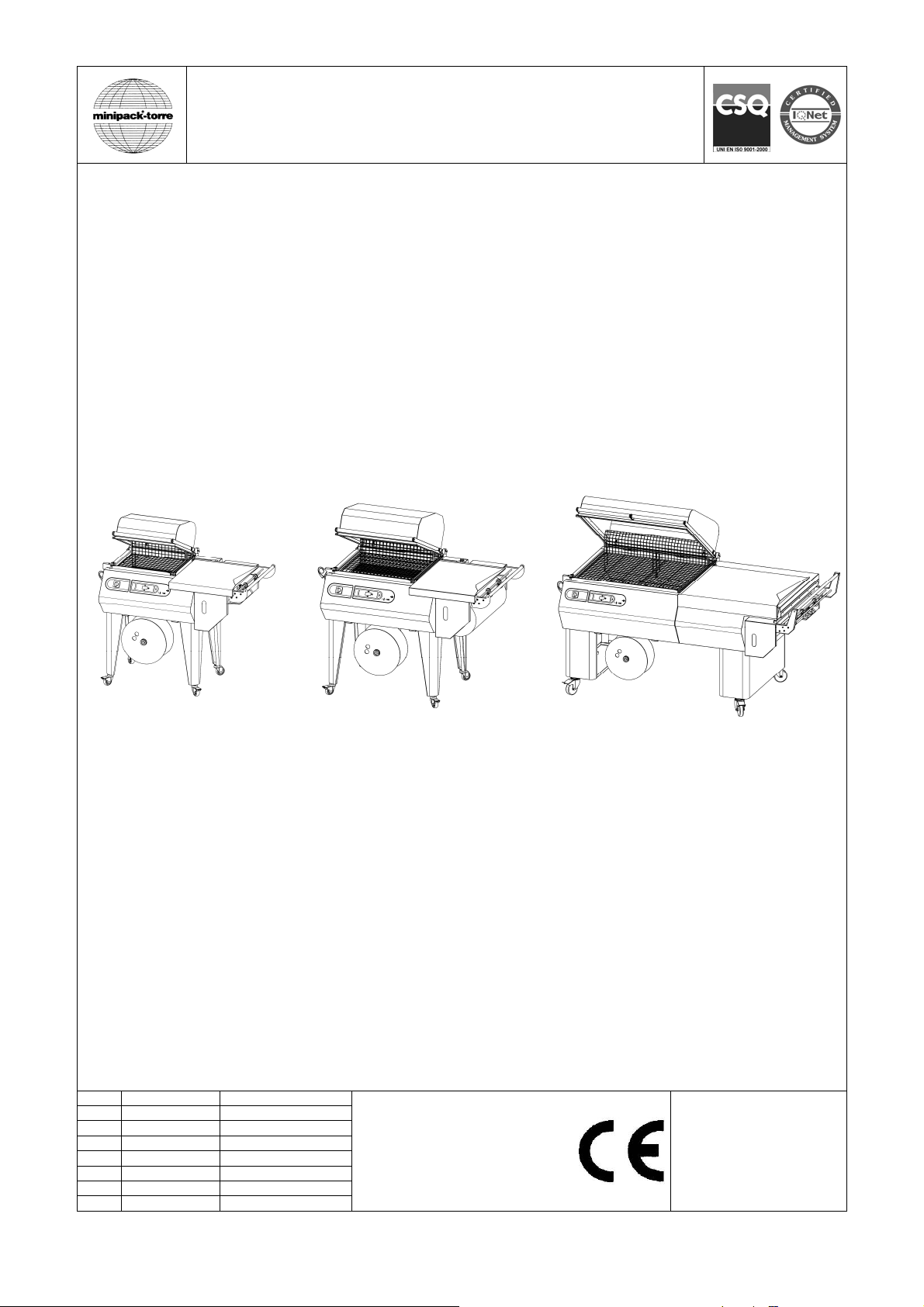
mod. RP40 mod. RP55 mod. RP85
IT LEGGERE ATTENTAMENTE QUESTE ISTRUZIONI PRIMA DI USARE LA MACCHINA
EN BEFORE USING THE MACHINE PLEASE CAREFULLY READ THE INSTRUCTIONS
DE BITTE LESEN SIE DIESE ANLEITUNG GENAU DURCH, BEVOR SIE DIE MASCHINE BENÜTZEN
FR PRIERE DE LIRE ATTENTIVEMENT CE MANUEL D’INSTRUCTIONS AVANT D’UTILISER LA MACHINE
ES LEER ATENTAMENTE ESTE MANUAL ANTES DE USAR LA MÁQUINA
PT ANTES DE USAR A MÁQUINA LER CUIDADOSAMENTE ESTE MANUAL
EL ∆ΙΑΒΑΣΤΕ ΜΕ ΠΡΟΣΟΧΗ ΤΙΣ ΠΑΡΑΚΑΤΩ Ο∆ΗΓΙΕΣ ΧΡΗΣΕΩΣ ΠΡΙΝ ΧΡΗΣΙΜΟΠΟΙΗΣΕΤΕ ΤΗ ΣΥΣΚΕΥΗ
ВНИМАТЕЛЬНО ОЗНАКОМЬТЕСЬ С ДАННЫМИ ИНСТРУКЦИЯМИ, ПРЕЖДЕ ЧЕМ ПРИСТУПИТЬ К РАБОТЕ С МАШИНО
RU
IT Italiano Pagina 01
EN English Page 14
DE Deutsch Seite 27
FR Français Page 40
ES Español Página 53
PT Português Página 66
EL Ελληνικά Σελίδα 79
RU Русский Cтраница 92
DOC. N. FM111131
REV. 01
ED. 01.2014

ISTRUZIONI ORIGINALI
Indice IT
Capitolo 1. Descrizione
1.1. Prefazione pagina 02
1.2. Caratteristiche della macchina pagina 02
1.3. Dati tecnici della macchina pagina 02
Capitolo 2. Caratteristiche del film
2.1. Films da adoperare pagina 02
2.2. Calcolo della fascia A pagina 03
Capitolo 3. Condizioni d’uso della macchina
3.1. Dimensioni e peso max. della confezione pagina 03
3.2. Ciò che si può confezionare pagina 03
3.3. Ciò che non si deve confezionare pagina 03
Capitolo 4. Norme di sicurezza
4.1. Avvertimenti pagina 03
4.2. Descrizione adesivi di sicurezza pagina 04
4.3. Dispositivi di protezione individuale pagina 04
Capitolo 5. Installazione della macchina
5.1. Trasporto e posizionamento pagina 05
5.2. Condizioni ambientali pagina 05
5.3. Collegamento elettrico pagina 05
Capitolo 6. Regolazione ed approntamento macchina
6.1. Controllo senso di rotazione (solo per mod. RP85) pagina 06
6.2. Regolazione pagina 06
6.2.1. Pannello comandi pagina 06
6.2.2. Accensione della macchina pagina 06
6.2.3. Selezione programmi e taratura variabili pagina 06
6.2.4. Messaggi di allarme pagina 08
6.3. Inserimento bobina film pagina 08
6.4. Posizionamento del piatto retinato pagina 09
6.5. Regolazione supporto bobina e piatto di confezionamento pagina 09
6.6. Esecuzione 1ª saldatura film pagina 09
6.7. Aggancio film all’avvolgitore (dove previsto) pagina 09
6.8. Introduzione dell’oggetto da confezionare pagina 09
6.9. Confezionamento pagina 10
Capitolo 7. Manutenzione ordinaria
7.1. Cautele per interventi di manutenzione ordinaria pagina 10
7.2. Pulizia lama saldante pagina 10
7.3. Rimozione di sfridi di film plastico e vari pagina 10
7.4. Pulizia della macchina pagina 10
7.5. Controllo liquido di raffreddamento (dove previsto) pagina 11
7.6. Cambio teflon e gomma pagina 11
7.7. Cambio lama saldante pagina 11
7.8. Soluzione dei problemi pagina 12
7.9. Smontaggio, demolizione e smaltimento residui pagina 12
Capitolo 8. Garanzia
8.1. Certificato di garanzia pagina 13
8.2. Condizioni di garanzia pagina 13
Dichiarazione CE di conformità pagina 105
Schema elettrico (vedi allegato)
1
Capitolo 1. Descrizione IT
1.1. Prefazione
Il presente manuale è redatto nel rispetto della norma UNI 10893 del Luglio 2000. È rivolto a tutti gli utilizzatori al fine di consentire un
corretto uso della macchina. Conservarlo in luogo facilmente accessibile vicino alla macchina e noto a tutti gli utilizzatori. Il presente
manuale è parte integrante della macchina ai fini della sicurezza. Per migliorare la comprensione precisiamo di seguito i simboli
utilizzati.
Tutti i diritti di riproduzione del presente manuale sono riservati alla ditta costruttrice. La riproduzione, anche parziale, è vietata a termini
di legge. Le descrizioni e le illustrazioni presenti in questo manuale non sono impegnative, di conseguenza la ditta costruttrice si riserva
il diritto di apportare in qualsiasi momento tutte le modifiche che riterrà opportune. Il presente manuale non può essere ceduto in visione
a terzi senza autorizzazione scritta della ditta costruttrice.
ATTENZIONE:
Norme antinfortunistiche per l’operatore. Tale avvertimento indica la presenza di pericoli che possono causare
lesioni a chi sta operando sulla macchina.
ATTENZIONE:
Organi caldi. Indica il pericolo di ustioni con rischio di infortunio, anche grave per la persona esposta.
ATTENZIONE:
Non toccare!
AVVERTENZA:
Indica la possibilità di arrecare danno alla macchina e/o ai suoi componenti.
1.2. Caratteristiche della macchina
Avete acquistato una macchina dalle caratteristiche e prestazioni eccezionali e Vi ringraziamo per la preferenza accordataci. Il sistema
di confezionamento è unico nel suo genere e si è affermato nel mondo con la presenza di oltre 200000 macchine operanti nel campo
dell’imballaggio e del confezionamento.
La validità del concetto tecnologico oltre che la qualità dei componenti e materiali impiegati nel processo produttivo e di collaudo sono la
migliore garanzia di un buon funzionamento e affidabilità nel tempo.
La macchina può essere utilizzata come macchina per saldatura e termoretrazione del film contemporanee, oppure come semplice
macchina saldatrice grazie al suo particolare circuito di funzionamento. In quest’ ultimo caso è possibile racchiudere l’oggetto in
sacchetti flosci senza termoretrazione.
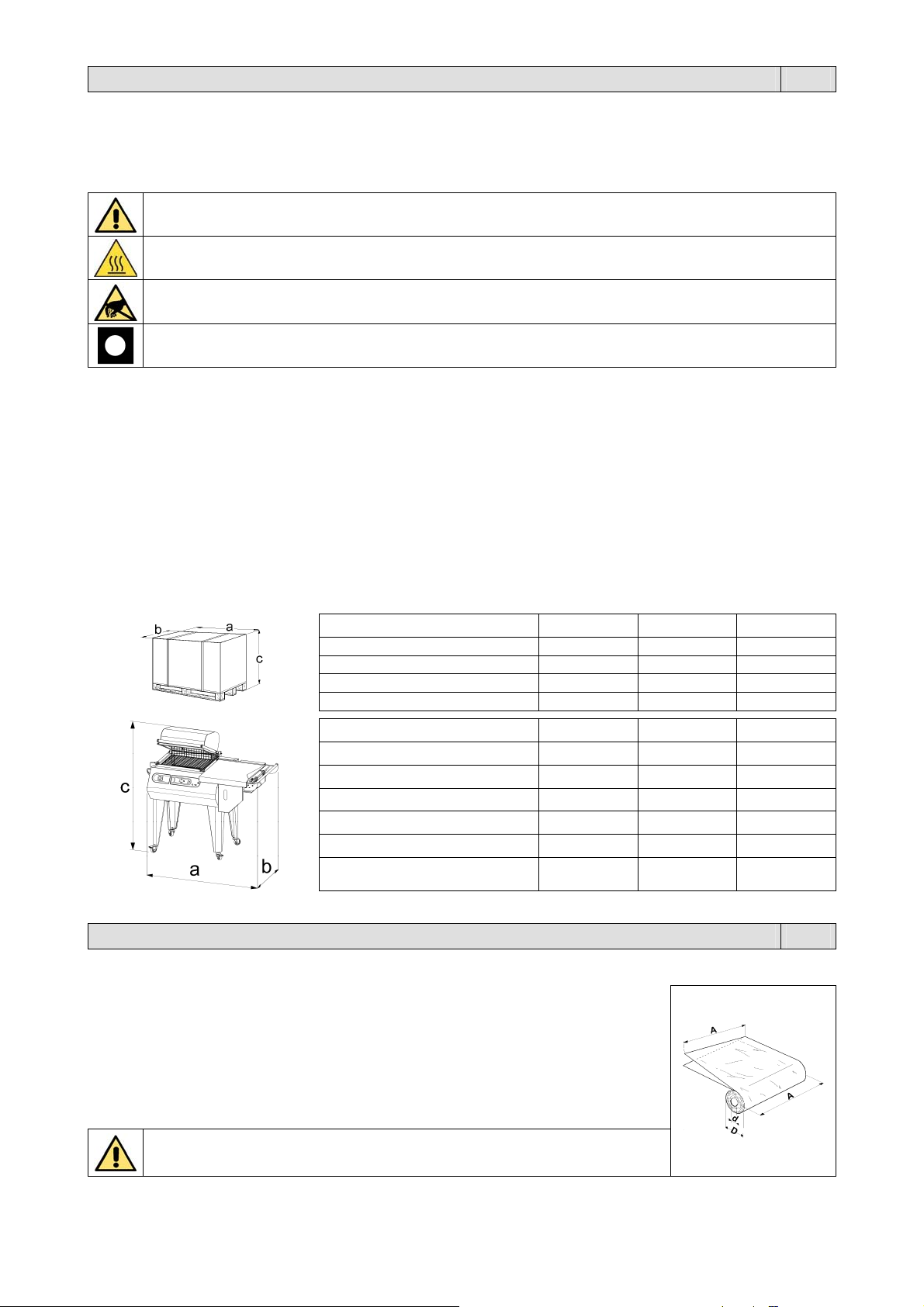
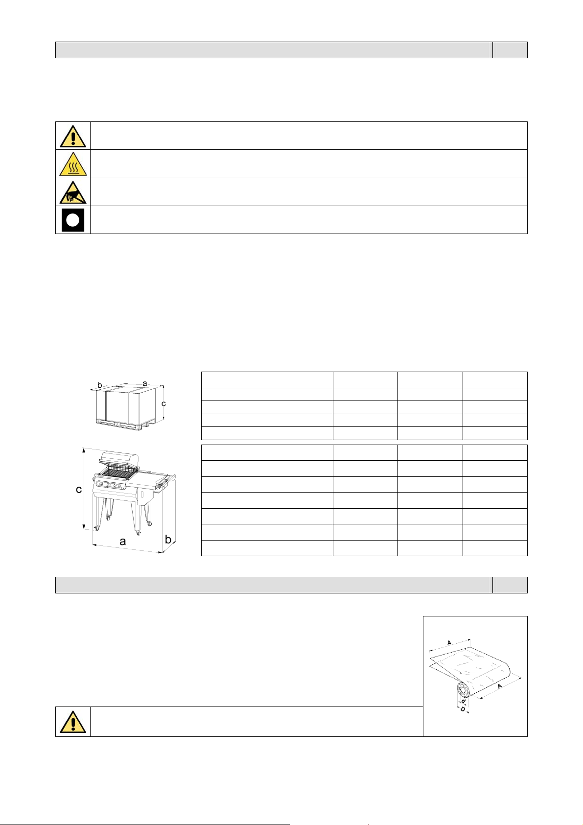
1.3. Dati tecnici della macchina
Larghezza “a”
Lunghezza “b”
Altezza “c”
Peso 114Kg 123Kg 264Kg
Larghezza “a”
Lunghezza “b”
Altezza “c” (campana chiusa)
Altezza “c” (campana aperta)
Peso 90Kg 99Kg 212Kg
Produzione massima
RP40 RP55 RP85
1330mm 1330mm 2180mm
1080mm 1080mm 1040mm
880mm 880mm 1430mm
RP40 RP55 RP85
1160mm 1260mm 1950mm
700mm 810mm 1000mm
1120mm 1165mm 1180mm
1220mm 1310mm 1480mm
300
confezioni/ora
300
confezioni/ora
300
confezioni/ora
Capitolo 2. Caratteristiche del film IT
2.1. Films da adoperare
La macchina può lavorare con tutti i films termoretraibili e non, con spessore da 15 a 50
micron sia di tipo tecnico che alimentare. Per garantire i migliori risultati è consigliato
l’utilizzo dei films da noi commercializzati. Le speciali caratteristiche dei nostri films danno
garanzie di affidabilità sia dal lato della corrispondenza alle normative di legge vigenti, che
dal lato sicurezza di ottimo funzionamento delle nostre macchine.
RP40 A = 500mm MAX D = 250mm MAX d = 77mm
RP55 A = 600mm MAX D = 250mm MAX d = 77mm
RP85 A = 800mm MAX D = 300mm MAX d = 77mm
Si raccomanda di consultare le schede tecniche e di sicurezza dei films
utilizzati e di attenersi alle prescrizioni descritte!
2
Capitolo 2. Caratteristiche del film IT
2.2. Calcolo della fascia A
Fascia A = b + c + 100mm
Per fascia “A” si intende la larghezza che deve avere la bobina di film per poter confezionare
il prodotto.
Capitolo 3. Condizioni d’uso della macchina IT
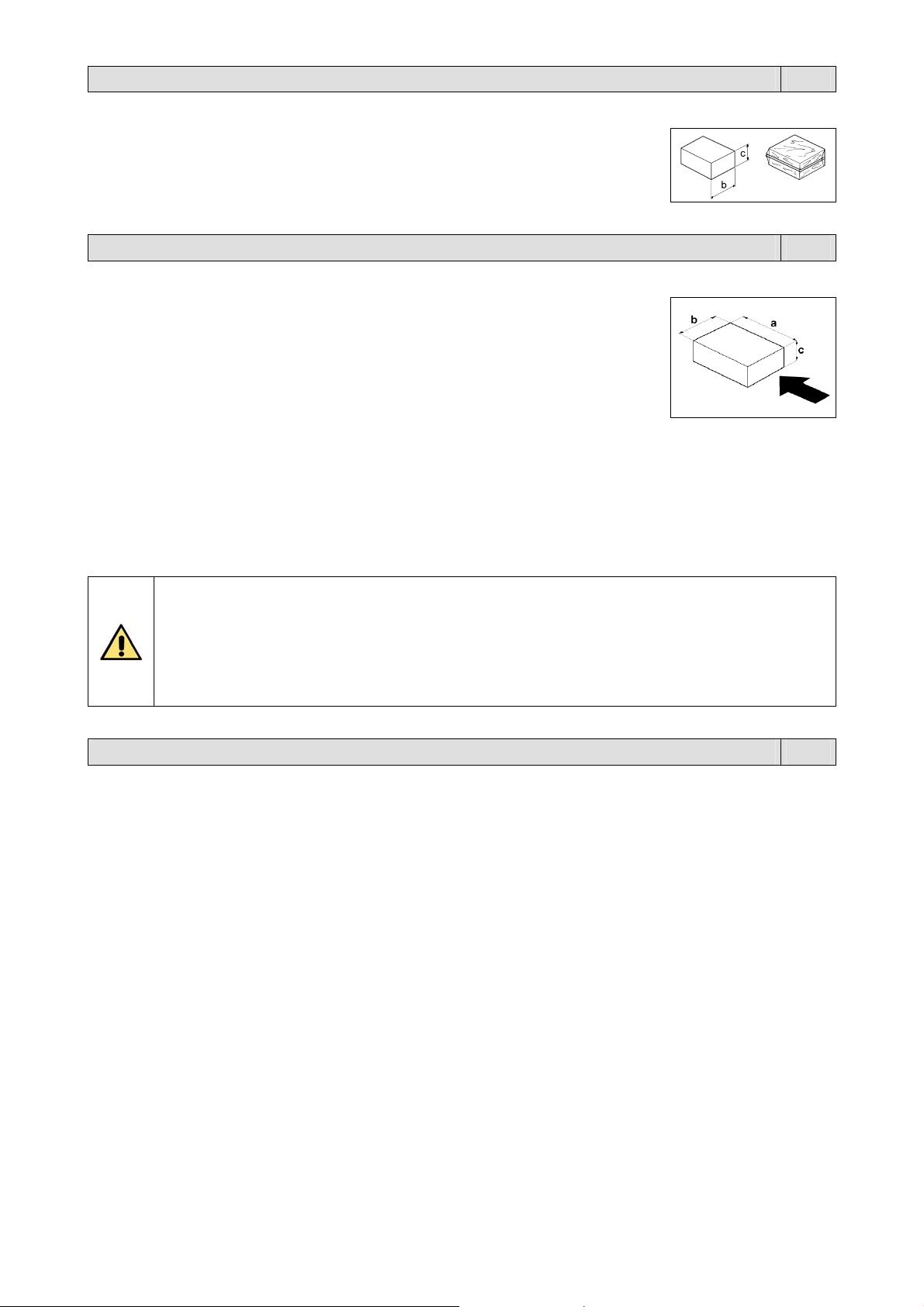
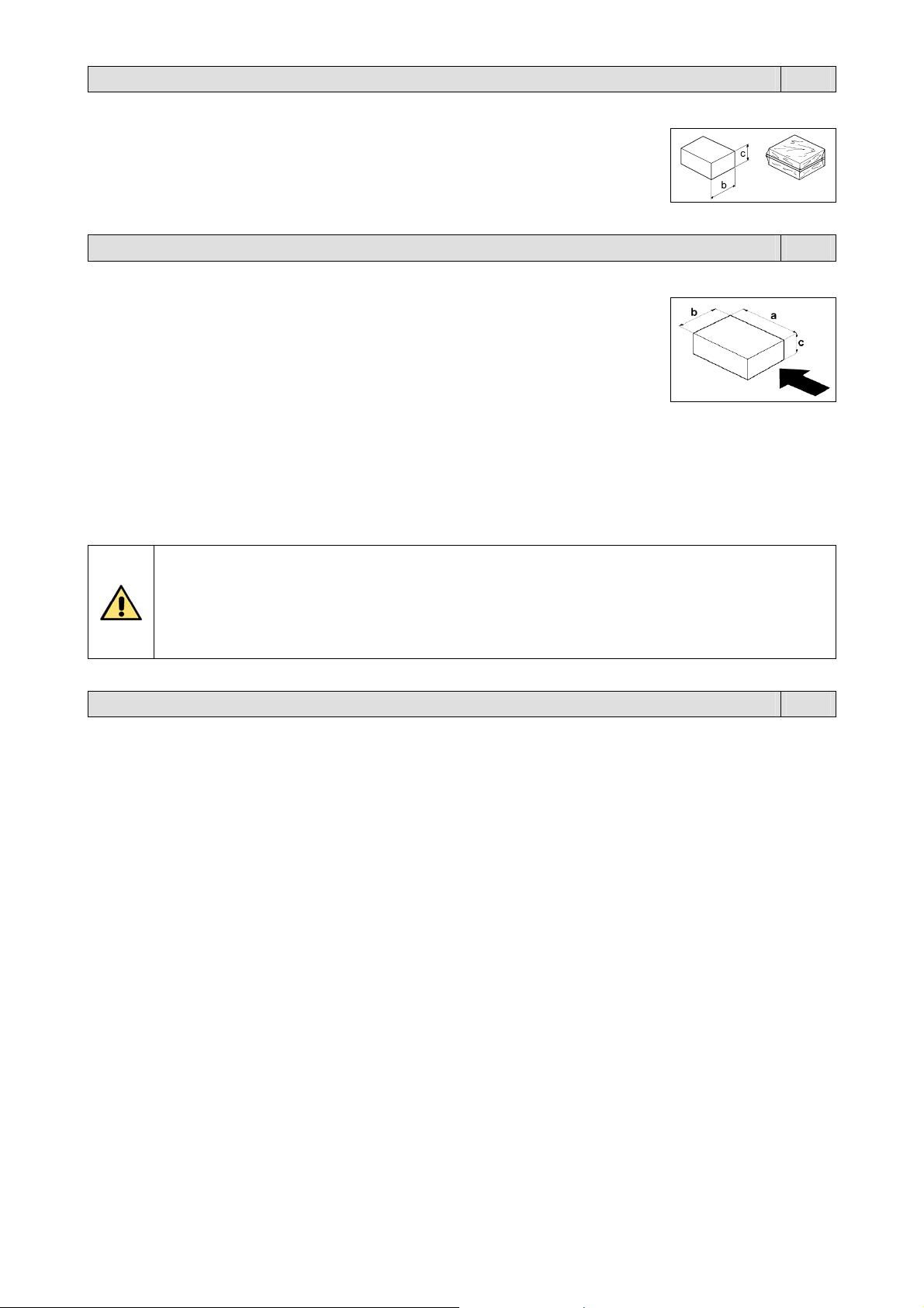
3.1. Dimensioni e peso max. della confezione
RP40 a = 400mm b = 250mm c = 160mm Peso = 10Kg
RP55 a = 500mm b = 380mm c = 200mm Peso = 15Kg
RP85 a = 800mm b = 500mm c = 200mm Peso = 18Kg
Nota: le misure indicate nella tabella si riferiscono alla misura max. della singola
dimensione. Per la misura max della confezione (b x c) bisogna comunque fare riferimento
al capitolo 2.2., dove si vede che, la somma di (b + c) é comunque uguale alla larghezza
della bobina del film meno 100mm.
3.2. Ciò che si può confezionare
Queste macchine sono in grado di confezionare una vasta gamma di prodotti completamente diversi tra loro, infatti sono
utilizzate con successo nei seguenti settori: alimentare, commercio, grafico e mailing, grande distribuzione, industria,
tessile.
3.3. Ciò che non si deve confezionare
E’ assolutamente vietato confezionare i seguenti tipi di prodotti per evitare di danneggiare in modo permanente la
macchina, oltre che provocare rischi di infortuni all’operatore addetto:
Prodotti bagnati e instabili
Liquidi di qualsiasi tipo e densità in contenitori fragili
Materiali infiammabili ed esplosivi
Bombolette con gas a pressione o di qualsiasi tipo
Polveri sciolte e volatili
Materiali sciolti con dimensioni più piccole dei fori del piatto retinato
Eventuali materiali e prodotti non previsti che possano in qualche modo essere pericolosi per l’utente e
provocare danni alla macchina stessa
Capitolo 4. Norme di sicurezza IT
4.1. Avvertimenti
È estremamente importante leggere attentamente questo capitolo in ogni sua parte poiché contiene importanti
informazioni sui rischi in cui l’operatore può incorrere in caso di uso errato della macchina. Queste norme fondamentali,
devono essere sommate a quelle specifiche esistenti nei paesi dove avviene l’installazione della macchina.
L’istallazione della macchina deve essere effettuata da personale tecnico addestrato e autorizzato.
La macchina non è destinata a essere usata da persone (bambini compresi) le cui capacità fisiche, sensoriali o
mentali siano ridotte, oppure con mancanza di esperienza o di conoscenza, a meno che esse abbiano potuto
beneficiare, attraverso l’intermediazione di una persona responsabile della loro sicurezza, di una sorveglianza o di
istruzioni riguardanti l’uso dell’apparecchio.
I bambini devono essere sorvegliati per sincerarsi che non giochino con la macchina.
Non usare la macchina per scopi diversi da quelli indicati dal contratto di vendita.
Non permettere al personale non autorizzato di riparare od eseguire qualsiasi intervento sulla macchina.
L’operatore deve essere a conoscenza delle avvertenze che gli competono e deve essere sempre informato dal
responsabile di reparto riguardo ai rischi relativi il suo lavoro.
Serrare bene attorno ai polsi le maniche dell’indumento da lavoro, abbottonandole in modo sicuro.
Curare lo spazio operativo ed i passaggi attorno alla macchina che devono essere sgombri da ostacoli, puliti ed
adeguatamente illuminati.
Eliminare ogni condizione pericolosa per la sicurezza prima di utilizzare la macchina ed avvertire sempre il
responsabile di reparto di ogni eventuale irregolarità di funzionamento.
Non utilizzare la macchina se in avaria.
È vietato manomettere i dispositivi ed i circuiti di sicurezza.
È vietato eseguire modifiche alla macchina senza l’autorizzazione del costruttore.
Se il cavo di alimentazione è danneggiato, esso deve essere sostituito dal costruttore o dal suo servizio assistenza
tecnica, o comunque da una persona con qualifica similare, in modo da prevenire ogni rischio.
3
Capitolo 4. Norme di sicurezza IT
Il quadro elettrico, durante il funzionamento, deve sempre rimanere chiuso.
Durante il funzionamento della macchina è vietato fumare!
È vietato eseguire qualsiasi operazione di manutenzione e/o regolazione durante il funzionamento della macchina.
Lo smontaggio dei ripari deve essere affidato solo ai manutentori addetti ed istruiti a tale scopo.
È vietato far funzionare la macchina senza prima aver ripristinato i ripari. Prima della messa in servizio, verificare la
corretta posizione dei ripari precedentemente rimossi.
In caso di allontanamento dell’operatore dalla macchina, spegnere la macchina mettendo l’interruttore generale
nella posizione “0” (OFF)!
Il costruttore declina ogni responsabilità per danni a persone o cose conseguenti l’inosservanza delle norme di
sicurezza.
NON PERMETTERE L’USO DELLA MACCHINA A PERSONALE NON ADDESTRATO!
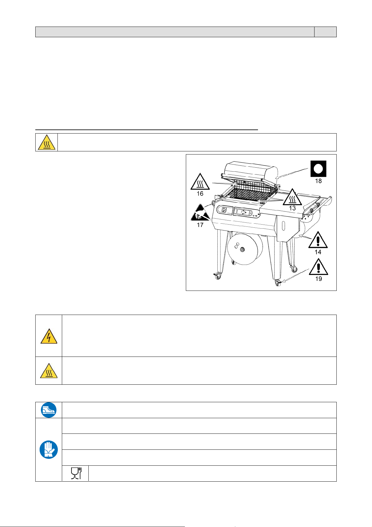
Durante le fasi di lavoro porre attenzione a tutte le parti calde della macchina che possono
raggiungere temperature tali da provocare ustioni.
Non toccare la lama saldante (13) subito dopo la
Non procedere nella saldatura nel caso di rottura della
Non toccare la paletta di chiusura polmone (16)
Non toccare la ventola in movimento o utilizzare la
Assicurarsi che la bobina di film sia alloggiata
Quando non si utilizza la macchina lasciare sempre la
Le ruote (19) devono essere utilizzate esclusivamente
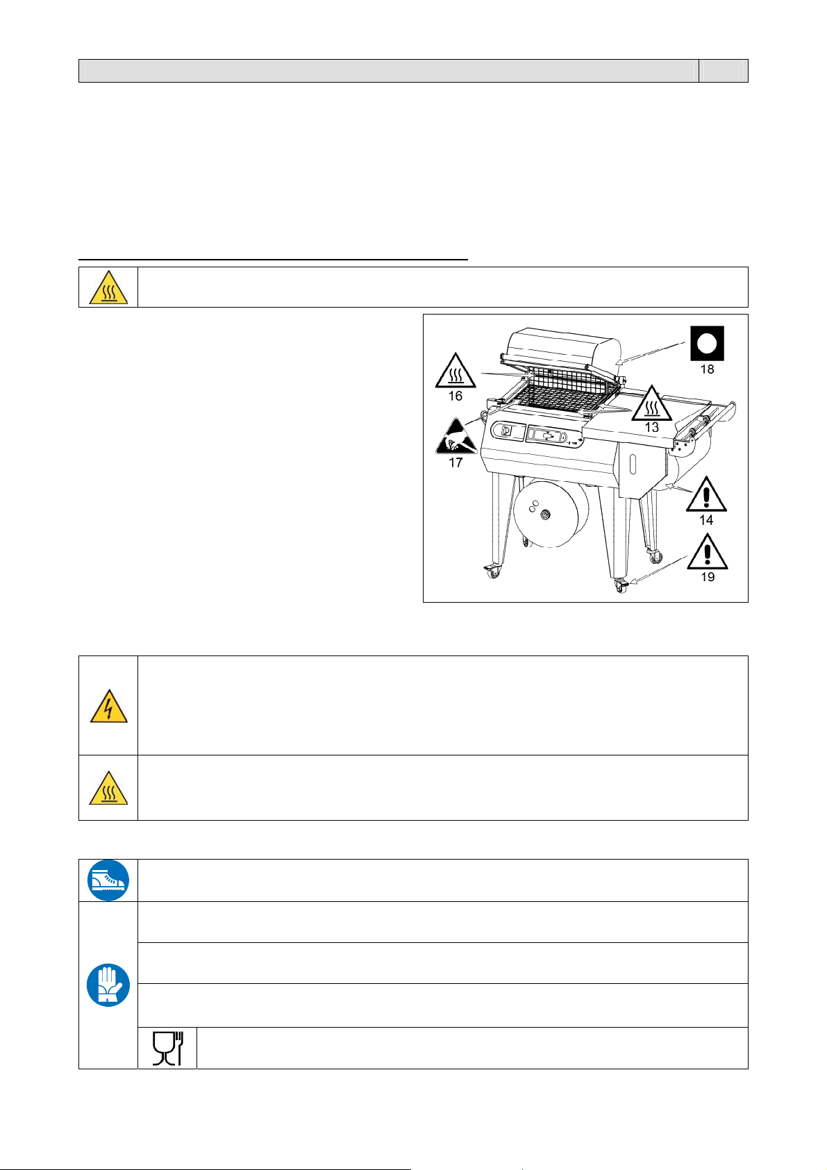
4.2. Descrizione adesivi di sicurezza
Sulla macchina sono presenti i seguenti adesivi di sicurezza:
4.3. Dispositivi di protezione individuale
saldatura, oltrepassando con la mano la barriera di
protezione antinfortunistica. Possibilità di scottature
dovute al residuo calore sulla lama saldante
lama saldante (13). Provvedere immediatamente alla
sua sostituzione
durante la fase di riscaldo. Possibilità di scottature
macchina senza il piatto retinato (17)
correttamente nella sua sede (14)
campana superiore (18) aperta
per “brevi” spostamenti su pavimenti lisci e orizzontali.
Sul pannello frontale della macchina.
Pericolo di folgorazione!
Rischio dovuto all’energia elettrica presente nell’impianto elettrico posto all’interno del pannello frontale.
In caso di apertura del pannello è necessario spegnere la macchina e scollegare la spina del cavo di
alimentazione dalla presa di corrente del circuito generale.
Durante il funzionamento della macchina il pannello frontale deve essere correttamente montato.
Sulla protezione posizionata davanti alla lama saldante.
Sul pannello di protezione del polmone di calore posizionato dietro al piatto retinato.
ATTENZIONE! Organi caldi. Indica il pericolo di ustioni con rischio di infortunio, anche grave per la
persona esposta.
Utilizzare scarpe di protezione resistenti all’urto, allo schiacciamento e alla compressione del piede
durante il trasporto e lo spostamento della macchina.
Utilizzare guanti di protezione dal pericolo di schiacciamento e dai pericoli meccanici durante il trasporto e
lo spostamento della macchina.
Utilizzare guanti di protezione contro il rischio di taglio durante le operazioni di cambio della lama
saldante.
Utilizzare guanti di protezione in base ai rischi dei materiali da confezionare (meccanici, chimici,…) che
resistano alle temperature di contatto con saldatura e/o lama saldante (massimo 100°C).
Utilizzare guanti di protezione per il contatto con alimenti durante l’uso in caso di
confezionamento di alimenti.
4
Capitolo 5. Installazione della macchina IT
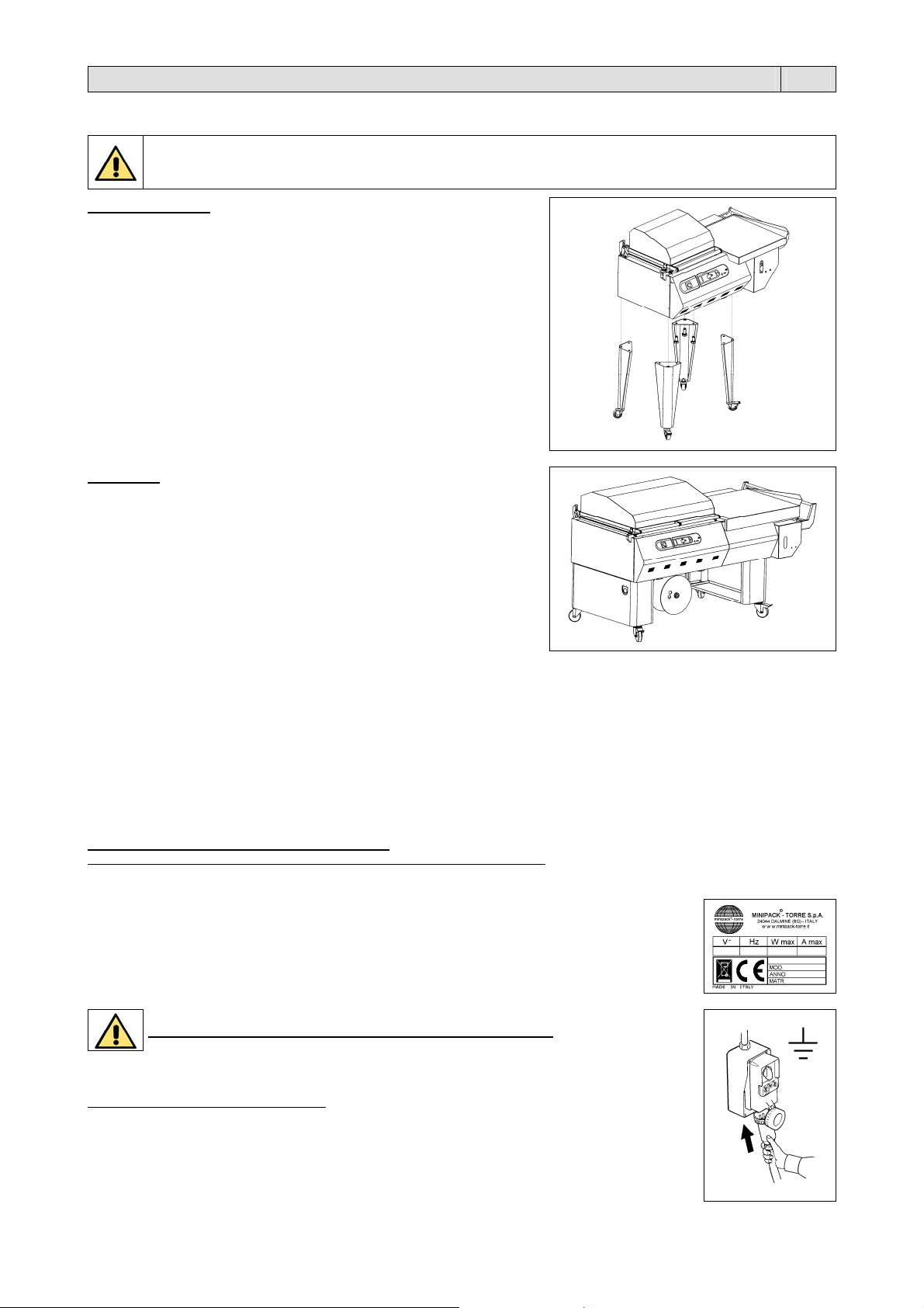
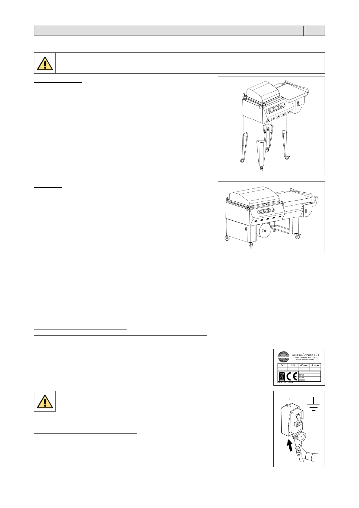
5.1. Trasporto e posizionamento
Nel trasporto e nel posizionamento della macchina si raccomanda di manovrare con molta cautela!
Prima di ogni movimentazione, assicurarsi che il mezzo di sollevamento sia idoneo a sollevare il
mod. RP40 – RP55
Tagliare con la forbice la reggia avendo cura di proteggersi gli occhi
con degli occhiali e sfilare il cartone. Togliere le viti e le eventuali
piastrine che fissano la macchina al pallet.
Se avete acquistato le gambe:
Togliere la scatola contenente le gambe
Sollevare la macchina con un carrello elevatore e fissare le 4 gambe
utilizzando le viti in dotazione
Liberare la campana superiore tagliando la cordina di ritegno.
Se avete acquistato l’avvolgitore sfrido:
Disimballare l’avvolgitore sfrido e posizionarlo come da istruzioni
allegate.
carico da movimentare!
mod. RP85
Tagliare con la forbice la reggia avendo cura di proteggersi gli occhi
con degli occhiali e sfilare il cartone. Togliere le viti e le eventuali
piastrine che fissano la macchina al pallet
Sollevare la macchina dal pallet utilizzando un carrello elevatore a
forche e posizionarla sul pavimento
Liberare la campana superiore tagliando la cordina di ritegno.
5.2. Condizioni ambientali
Posizionare la macchina accertandosi che sia livellata sul pavimento, in un ambiente adatto, privo di umidità, materiali infiammabili,
gas, esplosivi. La macchina deve essere installata solamente su superfici lisci, orizzontali e non infiammabili
Lasciare uno spazio minimo di 0,5m attorno alla macchina, per non ostruire le prese d’aria
Bloccare la macchina, una volta ottenuto il corretto posizionamento, agendo sul freno delle ruote.
Condizioni consentite negli ambienti in cui é collocata la macchina:
Temperatura da + 5°C a + 40°C
Umidità relativa da 30% a 90% senza condensazione.
L’illuminazione del locale di utilizzo deve essere conforme alle leggi vigenti nel paese in cui è installata la macchina e deve comunque
essere uniforme e garantire una buona visibilità, per salvaguardare la sicurezza e la salute dell’operatore.
GRADO DI PROTEZIONE DELLA MACCHINA = IP20
IL RUMORE AEREO PRODOTTO DALLA MACCHINA È INFERIORE A 70 dB(A)
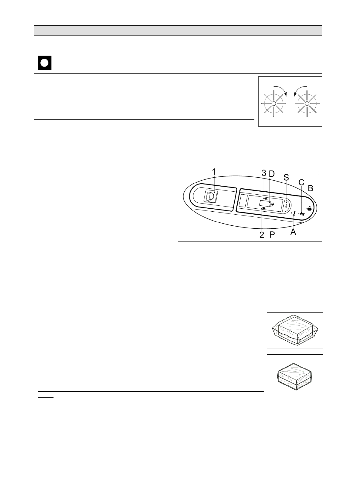
5.3. Collegamento elettrico
Tensione (V): vedere dati targhetta
Frequenza (Hz): vedere dati targhetta
Potenza massima assorbita (W): vedere dati targhetta
Corrente massima assorbita (A): vedere dati targhetta
Nota: per qualsiasi comunicazione con il costruttore, citare sempre il modello della macchina e il numero di
matricola indicati sulla targhetta applicata nella parte posteriore della macchina.
RISPETTARE LE NORME PER LA SICUREZZA SUL LAVORO!
Se la macchina non è dotata della spina di alimentazione utilizzare una spina adeguata ai valori di tensione e
amperaggio descritti nella targhetta dati e comunque conforme alle normative vigenti nel paese
d’installazione.
È OBBLIGATORIA LA MESSA A TERRA!
Prima di effettuare il collegamento elettrico assicuratevi che la tensione di rete corrisponda al voltaggio
indicato sulla targhetta applicata nella parte posteriore della macchina e che il contatto di terra sia conforme
alle norme di sicurezza vigenti. In caso di dubbi sulla tensione di rete contattate l’ente locale distributore
dell’energia elettrica.
Collegare la spina del cavo proveniente dal quadro elettrico della macchina in una presa di corrente del
circuito generale che sia facilmente raggiungibile dall’operatore.
5
Capitolo 6. Regolazione ed approntamento macchina IT
A
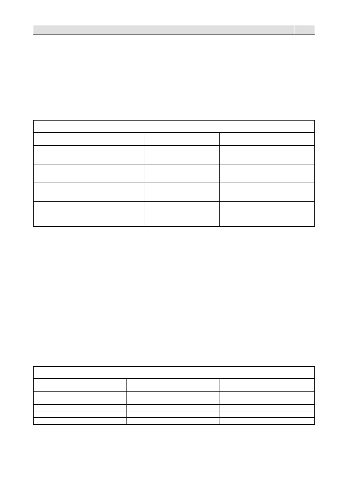
6.1. Controllo senso di rotazione (solo per mod. RP85)
Prima di mettere in funzione la macchina verificarne l’esatto senso di rotazione seguendo queste
istruzioni:
Ruotare l’interruttore generale (1) nella posizione 1.
bbassare la campana ed eseguire un ciclo di lavoro controllando che il senso di rotazione
delle ventole corrisponda alla figura.
Se la rotazione è nel senso opposto è necessario spegnere la macchina, togliere la spina di
alimentazione e invertire due delle tre fasi della spina.
Nota: Il controllo del senso di rotazione va eseguito ogni volta che si cambia presa di
alimentazione.
6.2. Regolazione
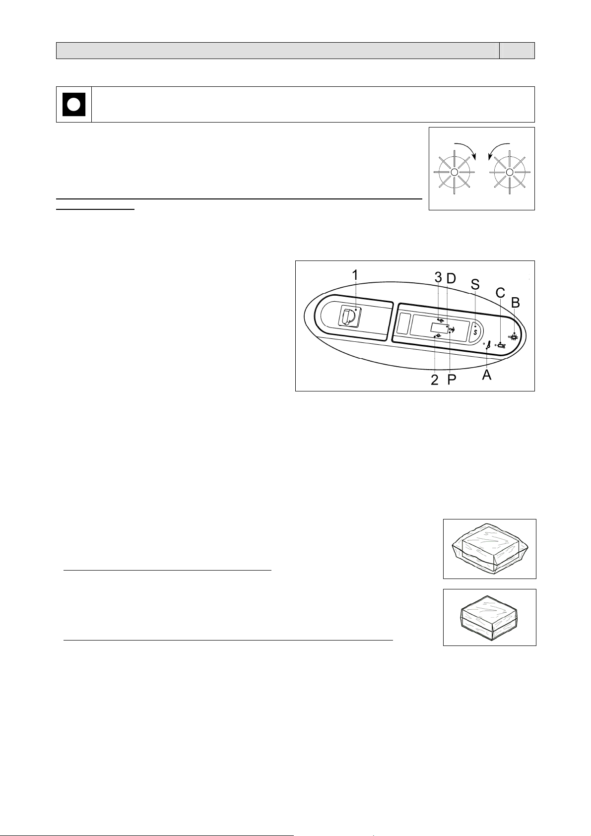
6.2.1.Pannello comandi
La macchina è dotata di un pannello di comando, dal quale è possibile impostare tutte le funzioni di programmazione e
funzionamento.
1 Interruttore generale.
2 Pulsante “DECREMENTA”. Riduce i valori delle
funzioni impostate
3 Pulsante “INCREMENTA”. Aumenta i valori delle
funzioni impostate
A Led temperatura
B Led retrazione
C Led saldatura
P Pulsante di selezione contacicli
D Display. Visualizza le funzioni selezionate e i relativi
dati di impostazione
S Pulsante di selezione programmi e variabili
6.2.2. Accensione della macchina
Ruotare l’interruttore generale (1) nella posizione 1.
Il display (D) si accende e compare il n° di programma attivo.
L’accensione della macchina (con i programmi P02÷P10) alimenta la resistenza di retrazione, che inizia a scaldarsi.
Prima di usare la macchina attendere che arrivi alla temperatura impostata segnalata dallo spegnimento della spia (A).
6.2.3.Selezione programmi e taratura variabili
La macchina ha 10 programmi selezionabili (P01÷P10).
Per selezionare il n° di programma premere i pulsanti (2) e (3).
Programma P01
Questo programma consente la sola saldatura del film.
Il film si fonde mediante il calore della lama saldante. La pressione tra la lama saldante ed il
contrasto superiore rivestito in teflon provoca la separazione dei due lembi di film.
Il prodotto da confezionare è racchiuso in un sacchetto floscio.
Programma P02÷P10
Questo programma consente contemporaneamente la saldatura e la retrazione del film.
La retrazione è prodotta dalla circolazione forzata di aria calda intorno alla confezione. Il
riscaldamento dell’aria si ottiene facendo passare la stessa attraverso una resistenza
(polmone di calore).
Il prodotto da confezionare è racchiuso in un sacchetto che aderisce perfettamente alla sua
forma.
In funzione del numero di programma sono impostabili più o meno variabili (si veda la tabella successiva).
L'ordine di programmazione dei programmi P02÷P10 è il seguente (per il programma P01 si può impostare solo il tempo
di saldatura):
1. Tempo di saldatura
2. Tempo ritardo ventola dopo la saldatura
3. Tempo di retrazione
4. Temperatura polmone
6
Capitolo 6. Regolazione ed approntamento macchina IT
V
Con il pulsante (S) si scorrono le variabili del programma scelto e con i pulsanti (2) e (3) si modificano i valori
memorizzati. Questi pulsanti (2) e (3) agiscono a passi di un digit ma se mantenuti premuti oltre un secondo il valore si
incrementa o decrementa in modo veloce.
Per convalidare le modifiche premere il pulsante (S) fino a far comparire sul display il n° di programma.
Il tempo di ritardo ventola dopo la saldatura é una variabile modificabile che non ha un led associato e pertanto viene
indicato con una “ r ” sul display sinistro, mentre le due cifre rimanenti indicano il tempo impostato.
Al termine di tutte le variabili programmabili il display mostrerà nuovamente il codice del programma appena editato (es.
P01).
Nota: Se durante la programmazione si chiude la campana, la macchina non funziona.
Eseguite tutte le regolazioni la macchina é pronta per procedere al confezionamento.
TABELLA DEI PARAMETRI IN FUNZIONE DEI PROGRAMMI
ariabile P01
Tempo di saldatura
(valori in secondi)
Min. = 0,0
Max. = 3,0
Default = 1,3
Tempo ritardo ventola dopo la saldatura
(valori in secondi)
Tempo di retrazione
(valori in secondi)
Temperatura polmone
non impostabile Min. = 0,0
non impostabile Min. = 0,0
non impostabile Min. = 0
il valore indicato corrisponde a:
0 = 0° (la resistenza è spenta)
1 … 150 = 100° … 398°C (2°C per punto)
CONTACICLI
Quando la macchina è in modalità SELEZIONE PROGRAMMI, il display mostra il programma in esecuzione (es “P01”).
Da questa modalità premendo il pulsante (P) si entra nella funzione “contacicli”.
Il display visualizza il numero dei cicli effettuati da quando la macchina è stata accesa.
Se poi tengo premuti contemporaneamente i pulsanti (2), (3) e (S) per 3 secondi si entra nella funzione “totalizzatore”.
Il display visualizza un numero che indica le “migliaia” di cicli eseguiti complessivamente dalla macchina.
Partendo da destra i numeri visualizzati indicano:
1° numero = migliaia di cicli
2° numero = decine di migliaia di cicli
3° numero = centinaia di migliaia di cicli
Premendo ancora il pulsante (2) il display mostra un numero che indica le unità.
Il display visualizza un numero che indica le “unità” di cicli eseguiti complessivamente dalla macchina.
Partendo da destra i numeri visualizzati indicano:
1° numero = unità di cicli
2° numero = decine di cicli
3° numero = centinaia di cicli
Premendo ancora il pulsante (2) si torna alla funzione “contacicli”.
Premendo infine il pulsante (P) si torna al funzionamento normale (il display mostra il programma in esecuzione).
TABELLA INDICATIVA DELL’IMPOSTAZIONE CICLO MACCHINA
Tempo di retrazione Tempo di pausa Temperatura polmone
6” 6”
5” 7”
4” 8”
3” 9”
2” 10”
(solo saldatura)
P02, 03, 04, 05, 06, 07, 08, 09, 10
(saldatura e retrazione)
Min. = 0,0
Max. = 3,0
Default = 1,3
Max. = 1,0
Default = 0,0
Max. = 10,0
Default = 2,5
Max. = 150
Default = 120
(valore indicato sul display)
7
Capitolo 6. Regolazione ed approntamento macchina IT
6.2.4. Messaggi d’allarme
La scheda elettronica prevede la rilevazione di alcuni allarmi che vengono segnalati tramite la visualizzazione sul display
(D) dei seguenti messaggi:
A: La tensione di alimentazione della macchina è inferiore (~ 10%) a quella prevista dalla rete.
È necessario sostituire la scheda di comando.
Contattare l’assistenza tecnica.
AL1: Finecorsa B1 chiuso all'accensione della macchina.
Le cause possono essere:
Macchina accesa con campana abbassata. Alzare la campana.
Finecorsa B1 guasto.
In entrambi i casi la macchina non esegue il ciclo ed è necessario aprire il contatto del finecorsa per annullare
la segnalazione. All’apertura del contatto l’allarme scompare.
AL2: Temperatura non raggiunta.
La temperatura di lavoro non è stata raggiunta nel tempo stabilito (15 min.).
Controllare che la termocoppia sia posizionata correttamente. Controllare la resistenza di riscaldamento.
Per resettare l’allarme spegnere e riaccendere la macchina.
AL3: Superamento temperatura massima o interruzione termocoppia.
La resistenza ha superato la temperatura massima consentita o la termocoppia è interrotta.
Controllare la termocoppia.
Per resettare l’allarme spegnere e riaccendere la macchina.
Se l’allarme ricompare è possibile un guasto al cavo flat della tastiera a membrana.
Controllare l’integrità del cavo e se guasto sostituire la tastiera a membrana.
AL4: Polarità termocoppia invertita.
Controllare il collegamento della termocoppia.
Per resettare l’allarme spegnere e riaccendere la macchina.
AL5: Protezione della lama saldante.
Per resettare l’allarme spegnere e riaccendere la macchina.
Se la macchina riprende a funzionare regolarmente significa che era stata effettuata una operazione impropria
(es. due saldature a brevissimo intervallo).
Se l’allarme ricompare significa che c’è un guasto sulla scheda di potenza.
Contattare l’assistenza tecnica.
ALL: Campana chiusa dopo la retrazione.
Se durante un ciclo di retrazione la campana resta chiusa oltre il tempo di retrazione impostato, la macchina
continua la retrazione per un tempo massimo di 10 secondi, oltre al quale si ferma.
Per resettare l’allarme è sufficiente aprire la campana.
EEE: Blocco macchina.
Contattare l’assistenza tecnica.
FF1:
FF2:
E_COM:
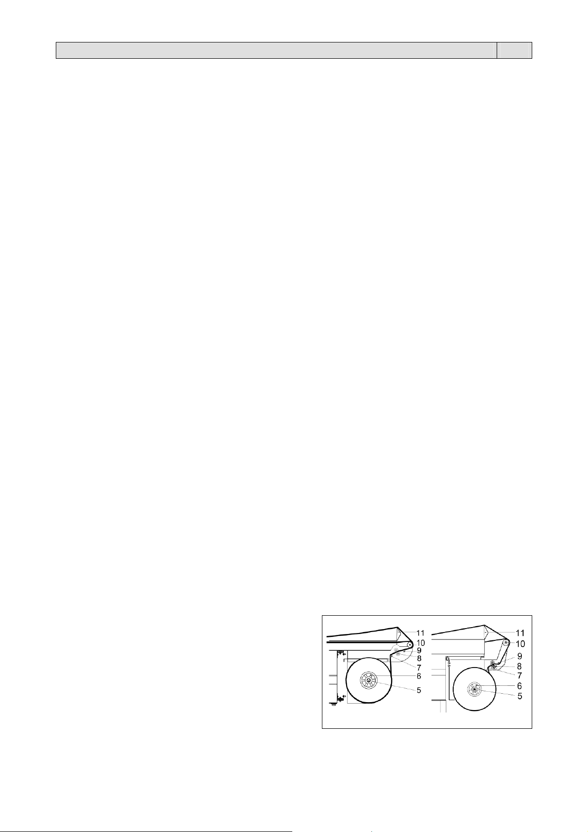
6.3. Inserimento bobina film
Inserire la bobina di film sul rullo (5) bloccandola mediante i
Posizionare il rullo sul supporto bobina
Passare il film intorno al rullo di rinvio (7)
Passare il film attraverso i microforatori (8)
Passare il film sopra il rullo di rinvio (9)
Passare il film intorno al rullo di rinvio (10)
Passaggio del lembo inferiore del film sotto il piatto di
Passaggio del lembo superiore del film sopra il piatto di
Memoria.
Per resettare l’allarme spegnere e riaccendere la macchina tenendo premuto per 3 secondi i pulsanti (2) e (3).
Un disturbo elettrico ha reso incomprensibile la comunicazione fra le schede.
Per resettare l’allarme spegnere e riaccendere la macchina.
coni centratori (6)
confezionamento (11)
confezionamento (11).
mod. RP40-RP55
mod. RP85
8
Capitolo 6. Regolazione ed approntamento macchina IT
A
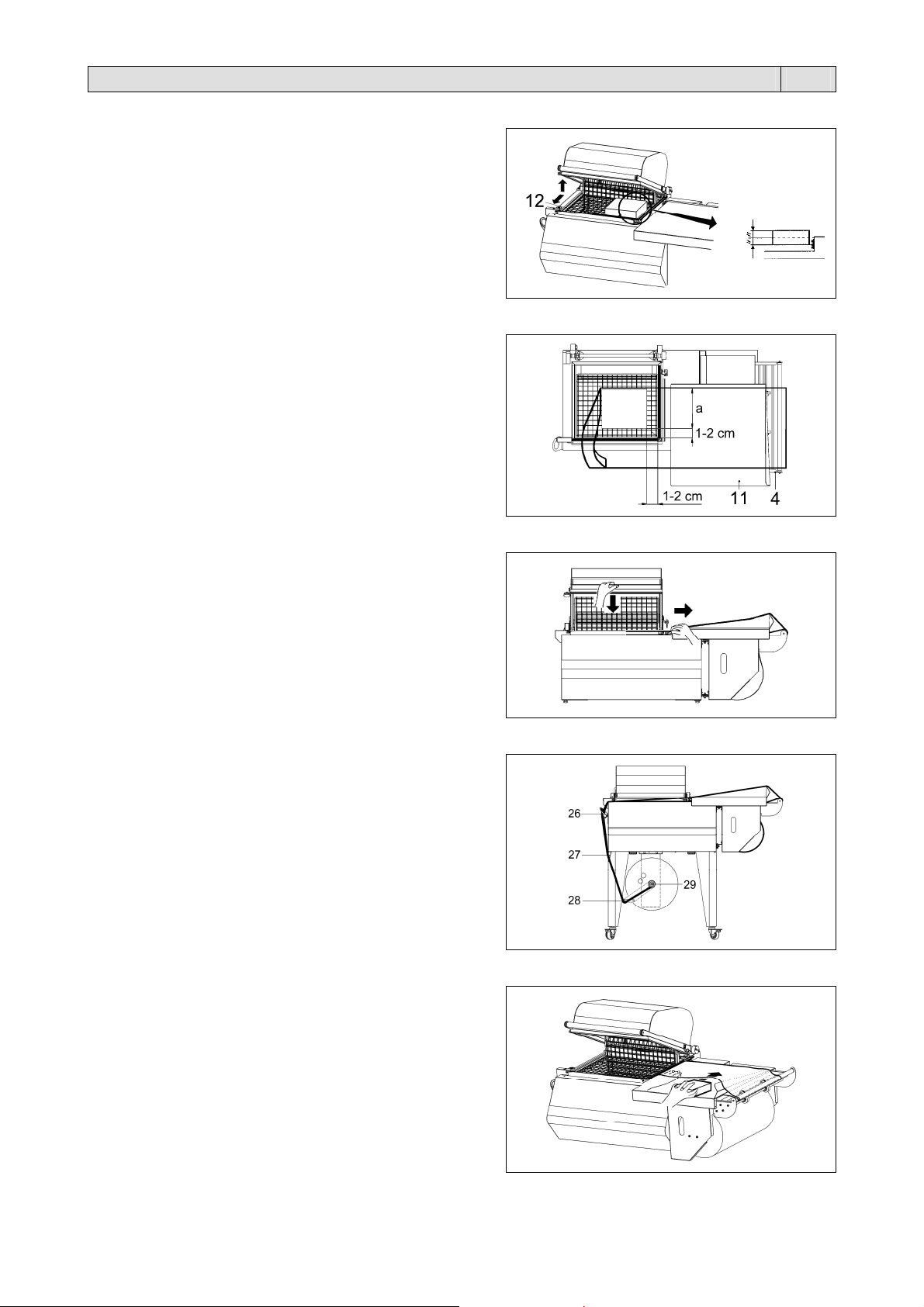
6.4. Posizionamento del piatto retinato
Il piatto retinato (12) può essere posizionato secondo l’oggetto da
confezionare.
Per una buona confezione il piatto retinato deve essere
posizionato in modo che la saldatura del film si trovi a metà
dell’altezza della confezione.
Per il suo posizionamento agire come:
Tirare il piatto secondo le frecce
Rimuovere il piatto dai riscontri
Riposizionare il piatto sui riscontri all’altezza desiderata.
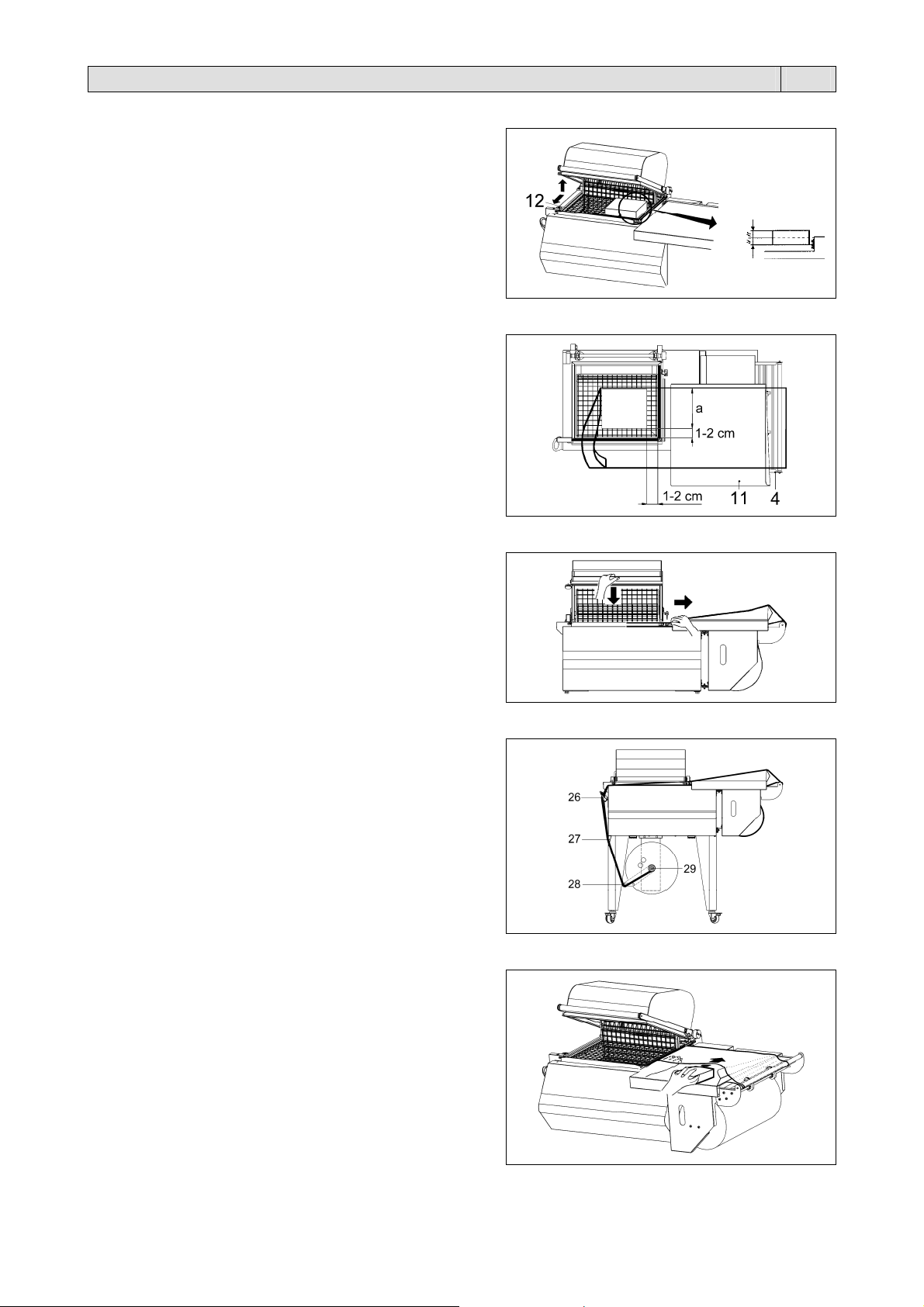
6.5. Regolazione supporto bobina e piatto di confezionamento
Il supporto bobina (4) e il piatto di confezionamento (11) devono
essere regolati in funzione della larghezza (a) dell’oggetto da
confezionare, lasciando circa 1-2 cm di spazio tra l’oggetto ed il
bordo di saldatura.
6.6. Esecuzione 1ª saldatura film
Per eseguire la 1ª saldatura portare il film come indicato in figura.
bbassare la maniglia della campana con la mano sinistra e
premere con una pressione di 10-15 Kg.
La macchina entrerà automaticamente in funzione e realizzerete
la 1ª saldatura sul lato sinistro del film.
Con la mano destra aiutate il distacco del film dalla lama
saldante.
6.7. Aggancio film all’avvolgitore (dove previsto)
Eseguire ora un numero di cicli sufficente a formare una striscia
di film di scarto.
Passarla intorno ai rullini di rinvio (26) e (27), al rullino di
comando (28) ed agganciarla all’avvolgitore (29).
Ora la macchina è pronta per procedere al confezionamento.
6.8. Introduzione dell’oggetto da confezionare
Sollevare con la mano sinistra il bordo del film sul piatto di
confezionamento.
Introdurre con la mano destra il prodotto nel film e farlo scorrere
verso sinistra fino a depositarlo sul piatto retinato lasciando circa
1-2 cm di spazio tra il prodotto ed il telaio interno di saldatura in
modo da permettere il passaggio dell’aria per la termoretrazione.
9
Capitolo 6. Regolazione ed approntamento macchina IT
6.9. Confezionamento
Premendo sulla maniglia della campana con una
pressione di circa 15 Kg. questa va ad appoggiarsi sulla
lama saldante. In questo modo avviene automaticamente
la saldatura del film sui lati aperti (destro e di fronte).
Se avete selezionato la funzione “SALDATURA +
RETRAZIONE” (programmi P02÷P10)
vedrete il film
retrarsi attorno al prodotto, diminuite allora leggermente la
pressione sulla maniglia della campana in modo da
permettere lo stacco del film dalla zona di saldatura
all’interno. Con la mano destra aiutate il distacco del film
dalle lame saldanti verso l’esterno.
Capitolo 7. Manutenzione ordinaria IT
7.1. Cautele per interventi di manutenzione ordinaria
LA MANUTENZIONE ORDINARIA DEVE ESSERE EFFETTUATA DA PERSONALE QUALIFICATO
OPPORTUNAMENTE ISTRUITO.
Prima di effettuare le operazioni di manutenzione spegnere la macchina agendo sull’interruttore
generale, togliere la spina dalla presa di rete e attendere il raffreddamento della macchina!
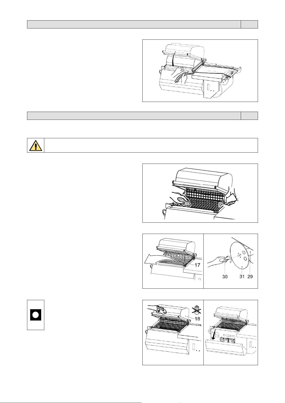
7.2. Pulizia lama saldante
Rimuovere con un panno asciutto i residui di film che si
possono depositare sulla lama saldante; effettuare
questa operazione subito dopo una saldatura in modo
che i residui, ancora caldi, possano essere asportati
con facilità
Per una migliore pulizia si consiglia di lubrificare
periodicamente la lama saldante con il grasso
antiadesivo al teflon fornito in dotazione con la
macchina.
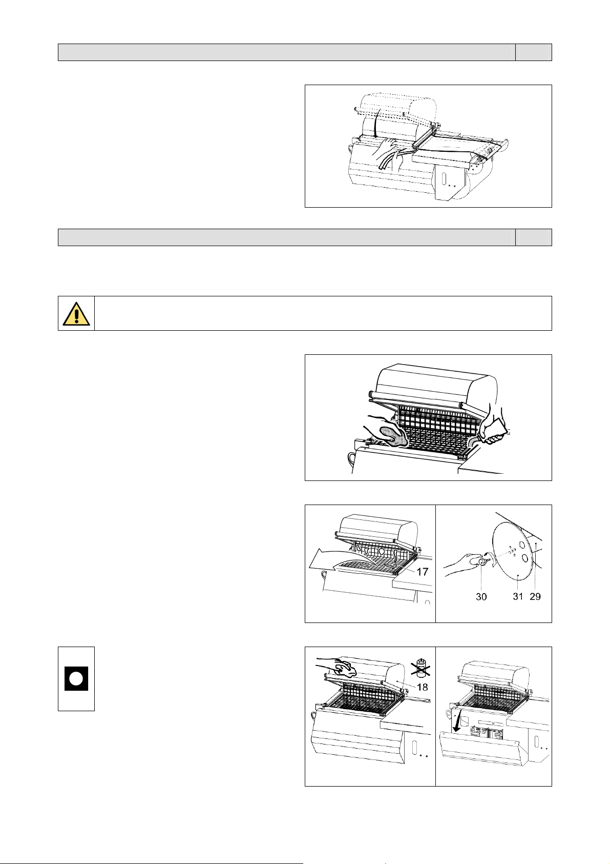
7.3. Rimozione di sfridi di film plastico e vari
Prima di rimuovere eventuali residui di film depositati
sulle parti calde della macchina (esempio sulla paletta
apri polmone calore), attendere che la macchina si sia
adeguatamente raffreddata
Nel caso di dover provvedere alla pulizia della
campana inferiore rimuovere il piatto retinato (17) ed
asportare i pezzi caduti all’interno (figura A)
Quando la bobina dell’avvolgitore automatico (29) è
piena, rimuovere il film svitando la manopola (30) e
togliendo il disco (31) (figura B).
7.4. Pulizia della macchina
Per la pulizia della campana superiore (18)
pulire sia l’esterno che l’interno esclusivamente
con acqua e sapone (figura A).
Non utilizzare detergenti con solventi che
potrebbero danneggiare la campana superiore
(18) e ridurne la trasparenza.
Per la pulizia della macchina utilizzare un panno
inumidito con acqua
Se la macchina lavora in ambiente polveroso é
necessario pulire con maggiore frequenza sia l’esterno
che l’interno della stessa. Si consiglia soprattutto di
aspirare la polvere che si deposita sui componenti
elettrici interni (figura B).
figura A
figura A
figura B
figura B
10
Capitolo 7. Manutenzione ordinaria IT
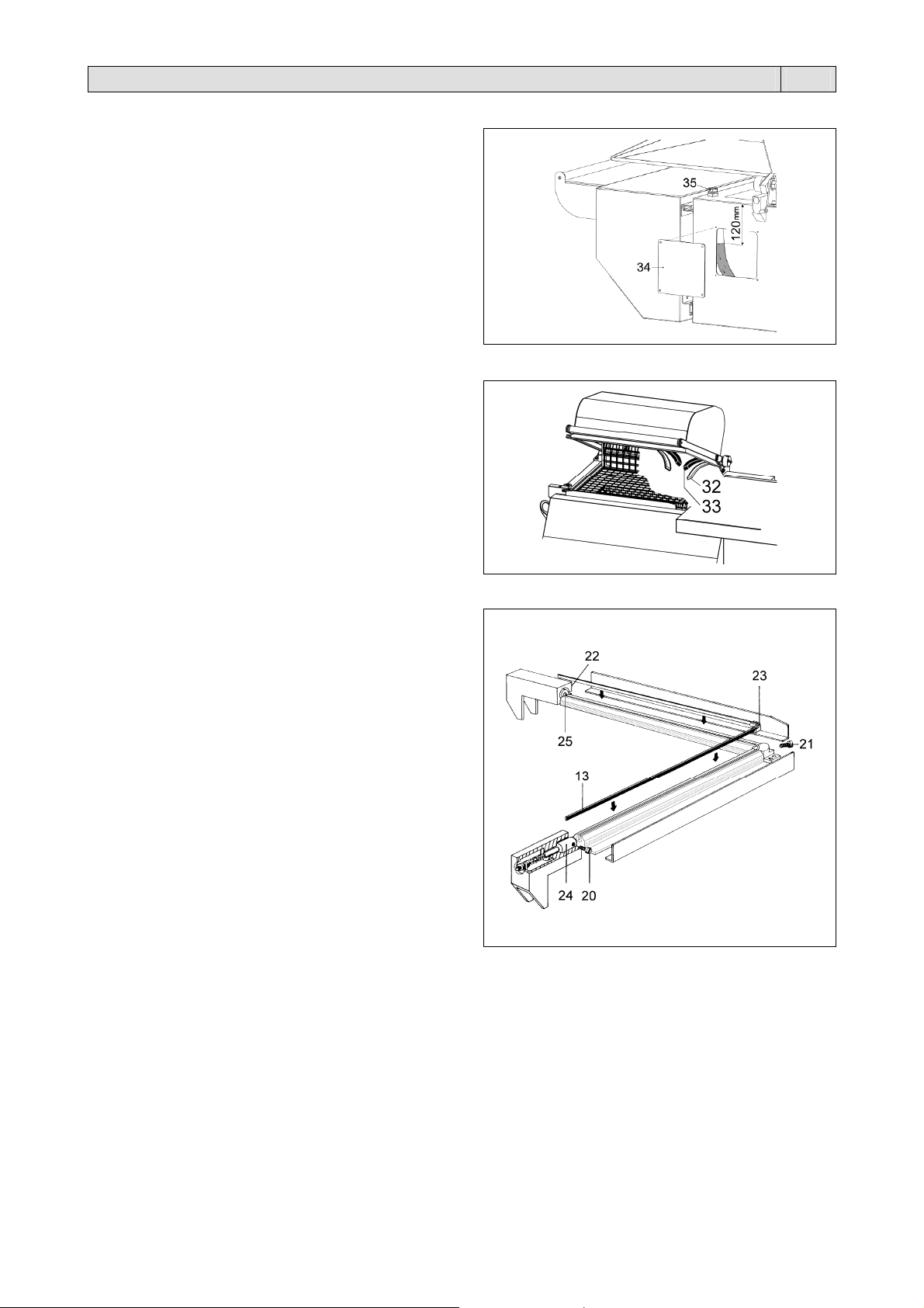
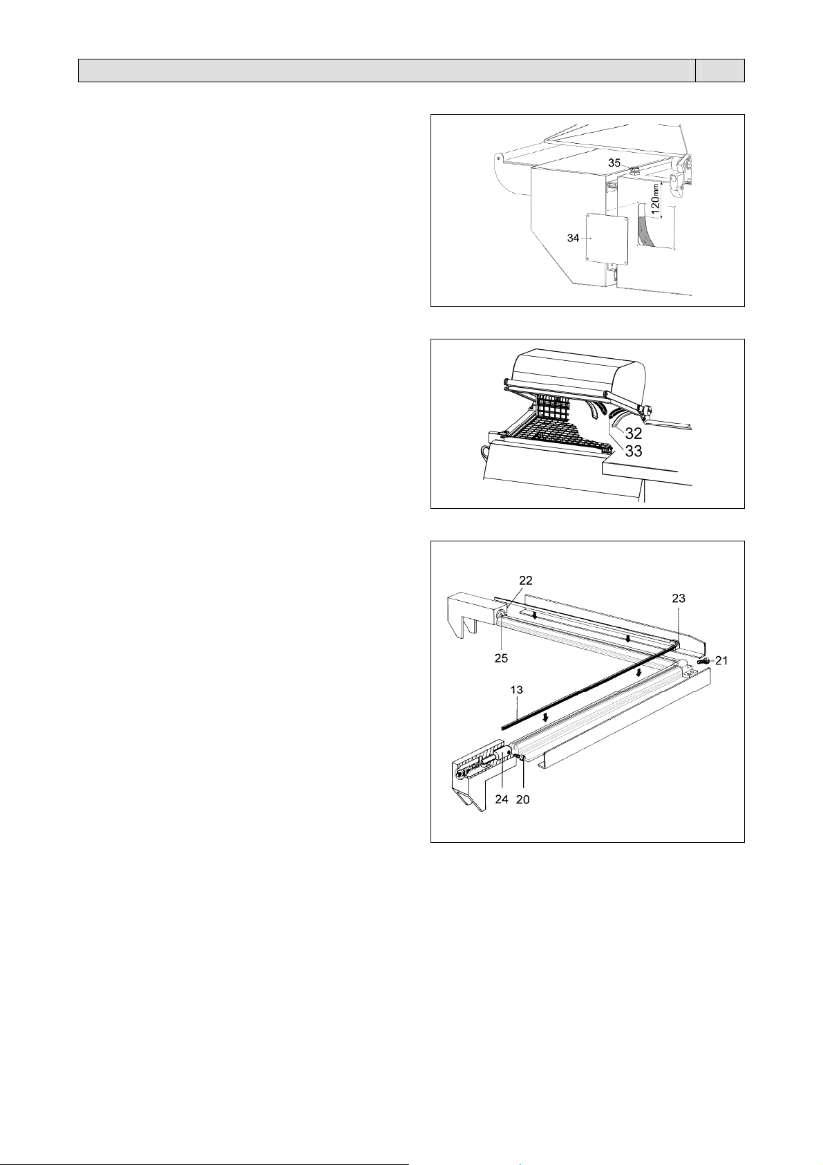
7.5. Controllo liquido di raffreddamento (dove previsto)
Controllare ogni 4 mesi il livello del liquido di raffreddamento
svitando il pannello posteriore (34).
Verificare che il livello del liquido non sia inferiore alla misura
indicata, altrimenti svitare il tappo (35) e aggiungere una
miscela di acqua e liquido anticongelante (10%).
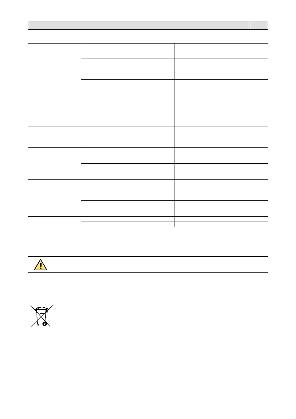
7.6. Cambio teflon e gomma
Quando i riscontri in teflon (32) sono troppo usurati, sostituirli
con quelli di ricambio facendo molta attenzione alla loro
applicazione, lineare e piana.
Pulire con detergente la gomma (33) prima dell’applicazione
del nastro di teflon autoadesivo.
Se anche la gomma (33) risulta deteriorata provvedere alla
sua sostituzione nel modo seguente:
Togliere la gomma vecchia
Pulire la sede che la contiene
Inserire la nuova gomma in modo lineare
Pulire la gomma con detergente
Applicare il nastro di teflon autoadesivo.
7.7. Cambio lama saldante
Per sostituire la lama saldante (13) seguire questa procedura:
Togliere tensione alla macchina
Svitare le 3 viti (20)-(21)-(22)
Togliere la lama saldante vecchia
Pulire la sede e se necessario sostituire il teflon isolante
(23) del morsetto centrale
Inserire la lama saldante nuova partendo dal morsetto
centrale e stringere la vite (21)
Rifilare la lama saldante nuova a filo del foro dei pistoncini
(24) e (25)
Completare l’inserimento della lama saldante in tutta la
sede
Spingere a fondo il pistoncino posteriore (24) verso la
lama saldante in modo che questa entri nel foro dello
stesso e stringere la vite (22)
Spingere a fondo il pistoncino anteriore (25) verso la lama
saldante in modo che questa entri nel foro dello stesso e
stringere la vite (20)
Rifilare il teflon sporgente dal morsetto centrale
Assicurarsi che la lama saldante sia posizionata bene ed
in tensione.
11
Capitolo 7. Manutenzione ordinaria IT
7.8. Soluzione dei problemi
PROBLEMA CAUSA SOLUZIONE
La macchina salda,
ma non termoretrae
La termoretrazione
avviene, ma non è
uniforme e completa
La termoretrazione
presenta delle “bolle”
(il film non aderisce al
prodotto)
La saldatura si apre
durante la
termoretrazione
La saldatura è
irregolare
La saldatura non
avviene
Presenza di fumo
durante la saldatura
Se dopo aver effettuato i suddetti controlli la macchina non dovesse funzionare ancora perfettamente,
contattate il servizio di assistenza descrivendo esattamente il difetto riscontrato.
7.9. Smontaggio, demolizione e smaltimento residui
ATTENZIONE!
Le operazioni di smontaggio e demolizione devono essere affidate a personale specializzato a tali attività e
dotato delle competenze meccaniche ed elettriche necessarie a lavorare in condizioni di sicurezza.
Procedere nel seguente modo:
Scollegare la macchina dalla rete di alimentazione elettrica
Smontare i componenti.
Ciascun rifiuto deve essere trattato, smaltito o riciclato in base alla classificazione ed alle procedure previste
dalla legislazione vigente nel paese di installazione.
Il simbolo indica che questo prodotto non deve essere trattato come rifiuto domestico.
Assicurando che il prodotto venga correttamente eliminato, si faciliterà la prevenzione di potenziali
conseguenze negative per l’ambiente e la salute dell’uomo, che potrebbero altrimenti essere causate da un
inappropriato trattamento del rifiuto di questo prodotto.
Per informazioni più dettagliate riguardo il riciclaggio di questo prodotto, contattare il venditore del prodotto,
o in alternativa il servizio di post vendita o l’appropriato servizio di trattamento dei rifiuti.
La temperatura del polmone di calore è
Aumentare il valore impostato
troppo bassa
Si sta lavorando con il programma P01 (solo
Cambiare programma
saldatura)
La macchina è in riscaldamento Attendere che la macchina arrivi alla
temperatura impostata (spegnimento della
spia “A”)
La ventola non gira Il motore della ventola è guasto.
Contattare l’assistenza tecnica.
È stata superata la temperatura massima
Contattare l’assistenza tecnica
del polmone di calore.
Il termostato di sicurezza è intervenuto,
scollegando la resistenza.
Il film non è idoneo o di scarsa qualità Sostituire il film
Le dimensioni del prodotto sono troppo
grandi
Le dimensioni del prodotto sono maggiori di
quelle consentite (vedi paragrafo 3.1.)
Il film è privo di microfori Far scorrere correttamente il film attraverso i
microforatori (vedi paragrafo 6.3.)
La lama saldante è sporca o danneggiata Pulire la lama saldante o sostituirla se
danneggiata
Il tempo di saldatura è errato Regolare il tempo di saldatura
La pressione della campana è insufficiente Aumentare leggermente la pressione sulla
maniglia della campana
Il film non è idoneo o di scarsa qualità Sostituire il film
Il tempo di saldatura è troppo basso Aumentare il valore impostato
La lama saldante non riceve corrente Riparare il circuito di alimentazione della
lama saldante.
Contattare l’assistenza tecnica.
Il Teflon e/o la guarnizione del coperchio
sono usurati
Sostituire il teflon e/o la guarnizione del
coperchio
La lama saldante è danneggiata Sostituire la lama saldante
Il tempo di saldatura è elevato Diminuire il valore impostato
Presenza di residui sulla lama saldante Pulire la lama saldante
12

Capitolo 8. Garanzia IT
8.1. Certificato di garanzia
La Garanzia ha validità 12 mesi dalla data di installazione alle condizioni riportate sul libretto d’istruzioni. Compilare il
retro della cartolina in ogni sua parte, strappare lungo la linea e spedire.
8.2. Condizioni di garanzia
La garanzia è valida 12 mesi e decorre dalla data di installazione della macchina. La garanzia consiste nella sostituzione
o riparazione gratuita di tutte quelle parti riscontrate da noi difettose per anomalie di materiali. Le riparazioni o
sostituzioni avvengono normalmente presso la casa costruttrice con l’addebito all’acquirente delle spese di trasporto o
manodopera. Qualora le riparazioni o sostituzioni vengano eseguite presso la sede dell’acquirente, quest’ultimo sarà
tenuto a pagare le spese di viaggio, trasferta e manodopera. Le prestazioni di garanzia vengono eseguite
esclusivamente a cura della casa costruttrice o dal rivenditore autorizzato. Per avere diritto a prestazioni di garanzia
inviare alla casa costruttrice od al rivenditore autorizzato il pezzo difettoso, perché sia effettuata la riparazione o
sostituzione. La riconsegna di tale pezzo riparato o sostituito, rientrerà nell’adempimento delle operazioni di garanzia. La
garanzia viene annullata:
Per il mancato immediato invio postale del CERTIFICATO DI GARANZIA al momento dell’acquisto, debitamente
compilato e firmato entro 20 giorni
Per la errata installazione, la inadeguata alimentazione, negligenza d’uso e manomissione da parte di persone non
autorizzate
Per modifiche effettuate sulla macchina senza il consenso scritto della casa
Qualora la macchina non sia più proprietà del primo acquirente.
La casa costruttrice declina a termine di legge ogni responsabilità per danni a persone o cose qualora venga
effettuata un’errata installazione o collegamento alla rete di alimentazione elettrica o esclusione della messa a
terra od in caso di manomissioni della macchina stessa. La casa costruttrice si riserva di approntare modifiche
e cambiamenti secondo esigenze tecniche e di funzionamento.
PER QUALUNQUE CONTROVERSIA LEGALE
IL FORO COMPETENTE È QUELLO DI BERGAMO (ITALIA).
13

TRANSLATION OF THE
ORIGINAL INSTRUCTIONS
Contents EN
Chapter 1. Description
1.1. Preface page 15
1.2. Machine features page 15
1.3. Machine technical data page 15
Chapter 2. Film features
2.1. Films to be used page 15
2.2. Band A calculation page 16
Chapter 3. Machine usage conditions
3.1. Max. weight and dimensions of the package page 16
3.2. Items that may be packaged page 16
3.3. Items which must not be packed page 16
Chapter 4. Safety standards
4.1. Warnings page 16
4.2. Description of safety stickers page 17
4.3. Individual protection devices page 17
Chapter 5. Machine installation
5.1. Transport and positioning page 18
5.2. Environmental conditions page 18
5.3. Electrical connections page 18
Chapter 6. Machine adjustment and setting up
6.1. Direction of rotation check (for mod. RP85 only) page 19
6.2. Adjustment page 19
6.2.1. Control panel page 19
6.2.2. Switching the machine on page 19
6.2.3. Program selection and variable setting page 19
6.2.4. Alarm messages page 21
6.3. Film reel insertion page 21
6.4. Reticulated plate installation page 22
6.5. Reel support and packaging plate adjustment page 22
6.6. Making the first seal page 22
6.7. Film binding on rewinder (if present) page 22
6.8. Introducing the object to be packaged page 22
6.9. Packaging page 23
Chapter 7. Ordinary maintenance
7.1. Instructions for ordinary maintenance work page 23
7.2. Sealing blade cleaning page 23
7.3. Plastic film and other scrap removal page 23
7.4. Machine cleaning page 23
7.5. Coolant check (if present) page 24
7.6. Substituting the rubber and Teflon page 24
7.7. Changing the sealing blade page 24
7.8. Problem solving page 25
7.9. Disassembling, demolition and elimination of residuals page 25
Chapter 8. Guarantee
8.1. Certificate of guarantee page 26
8.2. Guarantee conditions page 26
CE declaration of conformity page 105
Wiring diagram (see attachment)
14
Chapter 1. Description EN
1.1. Preface
This manual has been drawn up in compliance with the UNI10893 standard dated July 2000. It is meant for all users in order to enable
them to use the machine correctly. Keep it in a place which can be easily accessed in the proximity of the machine and which is known
to all users. This manual is an integral part of the machine for safety reasons. We wish to specify the symbols in use here below in order
to improve understanding of them.
All reproduction rights of this manual are reserved to the manufacturer. Partial or complete reproduction is forbidden as provided by the
law. Descriptions and pictures provided in this manual are not binding. Therefore the manufacturer, reserves the right to make any
change considered necessary. This manual cannot be transferred for viewing to third parties without authorisation in writing from the
manufacturing company.
ATTENTION:
Accident prevention rules for the operator. This warning indicates the presence of dangers which can injure the
person operating on the machine.
ATTENTION:
Hot parts. Shows the danger of burning, thus involving the risk of a serious accident for the exposed person.
ATTENTION:
Don’t touch!
WARNING:
It indicates the possibility of damaging the machine and/or its components.
1.2. Machine features
You have bought a machine with outstanding features and performance and we thank you very much for choosing it. The system is
unique and has achieved worldwide success with more than 200000 units operating in the packaging and wrapping sector.
The technological concept of its design, as well as the components and materials used in the manufacturing and testing process are the
best assurance of proper operation and lasting reliability.
Thanks to its particular operating circuit, it can be used both as a sealing and shrinking machine or as a sealing machine only. In the
latter case it is possible to pack the object in a soft bag without shrink-wrapping.
1.3. Machine technical data
Width “a”
Length “b”
Height “c”
Weight 114Kg 123Kg 264Kg
Width “a”
Length “b”
Height “c” (hood closed)
Height “c” (hood open)
Weight 90Kg 99Kg 212Kg
Maximum production 300 packs/hour 300 packs/hour 300 packs/hour
RP40 RP55 RP85
1330mm 1330mm 2180mm
1080mm 1080mm 1040mm
880mm 880mm 1430mm
RP40 RP55 RP85
1160mm 1260mm 1950mm
700mm 810mm 1000mm
1120mm 1165mm 1180mm
1220mm 1310mm 1480mm
Chapter 2. Film features EN
2.1. Films to be used
The machine can work with all heat-shrink and non-heat-shrink films, from 15 to 50 microns
in thickness, of a technical and food type. To guarantee the best results, use the films
marketed by us.
The special features of our films, with regard both to compliance with laws in force and to
excellent machine performance.
RP40 A = 500mm MAX D = 250mm MAX d = 77mm
RP55 A = 600mm MAX D = 250mm MAX d = 77mm
RP85 A = 800mm MAX D = 300mm MAX d = 77mm
Consult the data and safety sheets of the films in use and observe the
corresponding instructions!
15
Chapter 2. Film features EN
2.2. Band A calculation
Band A = b + c + 100mm
By band “A” we mean the width that the film must have to package the product.
Chapter 3. Machine usage conditions EN
3.1. Max. weight and dimensions of the package
RP40 a = 400mm b = 250mm c = 160mm Weight = 10Kg
RP55 a = 500mm b = 380mm c = 200mm Weight = 15Kg
RP85 a = 800mm b = 500mm c = 200mm Weight = 18Kg
Note: measurements shown refer to the maximum for the single dimension.
Refer to chapter 2.2. to get max. dimension of pack (b x c); the addition of (b + c) is equal to
film roll width minus 100mm.
3.2. Items that may be packaged
These machines are capable of packing a wide range of completely different products. They are used successfully in the
following sectors: food, marketing, graphics and mailing, large distribution, industry, fabrics.
3.3. Items which must not be packed
The products listed below must absolutely not be wrapped to avoid permanent damage to the machine and serious
injuries to the operator:
Wet and unstable products
Liquids of any kind and density in fragile containers
Flammable and explosive materials
Pressurised gas cylinder of any kind
Loose and volatile powders
Bulk materials with grain size smaller than the holes of the reticulated plate
Any materials and products not listed but which might harm operator and damage the machine.
Chapter 4. Safety standards EN
4.1. Warnings
It is extremely important to read this entire chapter as it contains important information regarding risks that personnel are
subject to in the event of incorrect use of the machine. These basic standards must be observed as well as specific
standards applicable in the country of installation.
The machine must be installed by trained and authorised technicians.
This machine is not intended for use by persons (including children) with reduced physical, sensory or mental
capabilities, or lack experience and knowledge, unless they have been given supervision or instruction concerning
use of the machine by a person responsible for their safety.
Children should be supervised to ensure that they do not play with the machine.
Never use the machine for purposes other than as specified in the sales contract.
Never allow unauthorised personnel to perform repairs or other operations on the machinery.
The operator must be familiar with all warnings related to the tasks in hand and always be informed by the head of
the site regarding risks.
Ensure that all clothing is tight fitting, with particular reference to cuffs or other loose clothing.
Ensure that all operating areas and transit zones are kept clear, clean and adequately lit at all times.
Eliminate all safety hazard conditions before using the machine and always notify the head personnel of any
malfunction.
Never use the machine in the event of fault.
Never tamper with safety devices or circuits.
Never perform modifications on the machine without prior authorisation from the manufacturer.
If the supply cord is damaged, it must be replaced by the manufacturer, its service agent or similarly qualified
persons in order to avoid a hazard.
16
Chapter 4. Safety standards EN
The electrical enclosure must remain closed during operation.
Smoking is forbidden while the machine is operating!
Never performs maintenance and/or adjustments to the machine during operation. Guards may only be
disassembled by suitably trained and qualified maintenance engineers.
Never operate the machine without all guards fitted. Ensure correct position of all guards before resuming normal
operation.
If it is necessary to leave the machine unattended, switch it off by turning the main switch to the “0” (OFF) position!
The manufacturer declines all liability for damage or phisical injury caused by failure to observe safety standards.
THE MACHINE CAN NOT BE USED BY UNTRAINED PERSONNEL!
During work pay attention to all hot parts of the machine. The temperature they can reach is so high
that it can cause burns.
Do not touch the sealing blade (13) soon after sealing by
Do not keep on sealing if the sealing blade breaks (13).
Do not touch the chamber closing flap (16) during warm-
Do not touch the fan while moving or using the machine
Make sure the film reel is properly lodged in is place (14)
When the machine is not in use, leave the upper hood
The wheels (19) must be used only for moving the unit
4.2. Description of safety stickers
The following safety stickers feature on the machine:
4.3. Individual protection devices
reaching beyond the safety guard. Danger of burns due
to residual heat on the sealing blade (13)
Replace it at once
up. Danger of burns
without the reticulated plate (17)
(18) open.
short distances across smooth, horizontal floors.
On machine front panel.
Danger of electrocution!
Risk due to presence of electrical power in electrical system inside front panel.
When the panel is opened, the machine must be switched off and the plug must be pulled from the socket
of the main circuit.
While the machine is running, the front panel must be mounted properly.
On the guard in front of the sealing blade.
On the protection panel of the heat diaphragm positioned behind the reticulated plate.
ATTENTION! Hot members. It shows the danger of burning, thus involving the risk of a serious
accident for the exposed person.
Wear safety shoes that protect feet from impacts, crushing and compression while moving or handling the
machine.
Wear safety gloves that protect the hands from crushing and mechanical hazards and while moving or
handling the machine.
Wear safety gloves that protect the hands against cutting risks while changing the sealing blade.
Wear safety gloves that protect the hands against the specific risks associated with the materials to be
packed (mechanical, chemical) and against coming into contact with the high temperatures present on the
seals and/or sealing blade (up to 100°C).
Wear safety gloves that prevent the hands from coming into contact with foodstuffs when
packaging them.
17
Chapter 5. Machine installation EN
5.1. Transport and positioning
Handle with great care during transport and positioning!
Before any movement, make sure that the lifting means is suitable for the load to be lifted!
mod. RP40 – RP55
Cut the strap with scissors make sure you protect your eyes by
If you have purchased the legs:
Remove the box containing the legs.
Raise the machine using a fork lift and fit the 4 legs using the screws
Cut the strap to release the upper hood.
If you have purchased the waste rewinder:
Unpack the waste rewinder and position it as indicated in the instructions
provided.
wearing glasses and withdraw the cardboard. Remove the screws and
any plate intended to fasten the machine to the pallet.
provided.
mod. RP85
Cut the strap with scissors make sure you protect your eyes by
wearing glasses and withdraw the cardboard. Remove the screws and
any plate intended to fasten the machine to the pallet.
Lift the machine by means of a fork lift truck and place it on the floor.
Cut the strap to release the upper hood.
5.2. Environmental conditions
Place the machine level on the floor in a suitable environment free from humidity, gases, explosives, combustible materials. The
machine may only be installed on smooth, flat non-inflammable surfaces.
Leave a minimum space of 0,5m around the machine so that not to obstruct air inlets
Once the correct position is achieved, lock the machine by means of the wheel brakes.
Working environment conditions:
Temperature from + 5°C to + 40°C
Relative humidity from 30% to 90%, without condensation.
The lighting of the operation room shall comply with the laws in force in the country where the machine is installed. However, it shall be
uniform and allow good visibility in order to safeguard the operator’s safety and health.
MACHINE PROTECTION FACTOR = IP20
THE AIRBORNE NOISE MADE BY THE MACHINE IS LOWER THAN 70 dB(A)
5.3. Electrical connections
Voltage (V): see data on plate
Frequency (Hz): see data on plate
Maximum absorbed power (W): see data on plate
Maximum absorbed current (A): see data on plate
Note: when contacting the Manufacturer, always indicate the model and the serial number specified on the
plate on the rear part of the machine.
OBSERVE HEALTH AND SAFETY REGULATIONS!
If the machine is not equipped with the power supply plug, use a plug that is suitable for the voltage and
amperage values described by the rating plate and that can comply with the rules in force in the installation
country.
GROUNDING OF THE UNIT IS OBLIGATORY!
Before making electrical connections, make sure the mains voltage matches the one on the plate on machine
rear and that the ground contact complies with the safety rules in force.
In case of doubts about the mains voltage, contact the local power supply company.
Insert the plug on the cable from machine electrical cabinet in a mains power supply socket that can be
reached easily by the operator.
18
Chapter 6. Machine adjustment and setting up EN
6.1. Direction of rotation check (for mod. RP85 only)
Before starting the machine operation check the right direction of rotation following these
instructions:
Rotate the main switch (1) on 1-position.
Lower down the upper hood and execute a work cycle by making sure that the direction of
rotation of the fans will correspond to figure.
If it rotates in the opposite direction to this, it is necessary to shutdown the machine, remove
the power supply plug and invert two of the three-phases of the plug.
Note: The control of direction of rotation should be carried out each time you change
the electrical plug.
6.2. Adjustment
6.2.1. Control panel
The machine is fitted with a control panel, from which all programming and operation functions can be set.
1 Main switch
2 Button “DECREASE”. Reduces set function values
3 Button “INCREASE”. Increases set function values
A Temperature warning light
B Shrinking warning light
C Sealing warning light
P Cycle counter selection button
D Display. Displays selected functions and relative
settings
S Programme and variable selection button
6.2.2. Switching the machine on
Turn the main switch (1) into pos. 1.
The display (D) turns on and the number of the currently selected program will appear.
Switching the machine on (with programs P02÷P10) powers the shrinking heat element which begins to heat up.
Before using the machine, wait until the adjusting temperature is reached. This is signalled by the extinction of the
warning light (A).
6.2.3. Program selection and variable setting
The machine is equipped with 10 selectionable programs (P01÷P10).
Push buttons (2) and (3) to select the number of the program.
Program P01
This program is for film sealing only.
The film melts due to the heat of the sealing blade. The pressure between the sealing blade
and the upper contrast lined in Teflon separates the 2 edges of the film.
The product to be packed is enclosed in a slack bag.
Program P02÷P10
This program seals and shrinks film simultaneously.
Shrinking is produced by the forced circulation of hot air around the the package. Air is heated
by passing through a heat element (heat diaphragm).
The product to be packed is enclosed in a bag which perfectly adheres to its shape.
The number of settable variables will depend upon the programme number (see the following table).
The programmes P02÷P10 must be programmed in the following order (only the sealing time can be set up for
programme 01):
1. Sealing time
2. Fan delay time after sealing
3. Shrinking time
4. Heat chamber temperature
19
Chapter 6. Machine adjustment and setting up EN
V
Through button (S) it is possible to look through the variables of the selected program, while through buttons (2) and (3)
the memorized values can be modified. These buttons (2) and (3) act by one digit at a time, but if they are held down for
more than a second, the value will rapidly increase or decrease.
To validate modifications, press button (S) until the number of the program appears on the display.
The fan delay time after sealing can be modified; there is not a LED indicating this variable which is shown with an “r” on
the left display, whereas the two remaining digits will indicate the set up time.
At the end of all variables to be adjusted, the display will show the code of the program just chosen (for example P01).
Note: If the hood is closed during the programming phase, the machine will not work.
Once all adjustments have been made, the machine is ready to start working.
TABLE OF PARAMETERS ACCORDING TO PROGRAMMES
ariable P01
Sealing time
(values expressed in seconds)
Min. = 0,0
Max. = 3,0
Default = 1,3
Fan delay time after sealing
not settable Min. = 0,0
(values expressed in seconds)
Shrinking time
not settable Min. = 0,0
(values expressed in seconds)
Heat chamber temperature
not settable Min. = 0
the indicated value will correspond to:
0 = 0° (the heating element is switched off)
1 … 150 = 100° … 398°C (2°C each point)
CYCLE COUNTER
When the machine is in the PROGRAMS SELECTION mode, the display will show the programme that is being run (e.g.
“P01”).
In this mode, press button (P) to activate the “cycle counter” function”.
The display indicates the number of cycles since the machine was switched on.
Then, press and hold buttons (2), (3) and (S) simultaneously for 3 seconds to activate the “totalizer” function.
The display indicates a figure corresponding to the total number of cycles performed by the machine, expressed in
thousands.
Starting from the right, the numbers that appear on the display indicate:
st
number = thousands of cycles
1
nd
2
number = tens of thousands of cycles
rd
number = hundreds of thousands of cycles
3
Press button (2) again and the display indicates a number corresponding to the units.
The display indicates a figure corresponding to the total number of cycles performed by the machine, expressed in units.
Starting from the right, the numbers that appear on the display indicate:
st
1
number = single cycles
nd
number = tens of cycles
2
rd
3
number = hundreds of cycles
Press button (2) again to return to the “cycle counter” function
Finally, press button (P) to return to normal operation (the display shows the current programme).
APPROXIMATE TABLE OF MACHINE CICLE ADJUSTEMENT
Shrinking time Pause time Heat chamber temperature
6” 6”
5” 7”
4” 8”
3” 9”
2” 10”
(sealing only)
P02, 03, 04, 05, 06, 07, 08, 09, 10
(sealing and shrinking)
Min. = 0,0
Max. = 3,0
Default = 1,3
Max. = 1,0
Default = 0,0
Max. = 10,0
Default = 2,5
Max. = 150
Default = 120
(value indicated on the display)
20

Chapter 6. Machine adjustment and setting up EN
6.2.4. Alarm messages
The electronic board detects series of alarms that are indicated on the display (D) by the following messages:
A: The machine power voltage is below (~ 10%) that provided by the network.
The control board must be replaced.
Contact the after-sales technical assistance.
AL1: Limit switch B1 closed when the machine is switched on.
Possible causes are:
Machine on and hood down. Lift the hood.
Limit switch B1 faulty. Repair or replace the limit switch.
The machine will not execute the cycle in both cases. It is necessary to open the limit switch contact to cancel
signalling.
The alarm will disappear as soon as the contact is opened.
AL2: Temperature not reached.
The working temperature was not reached in the pre-set time (15 min.).
Check that the thermocouple is positioned correctly. Check the heating element.
To reset the alarm, switch the machine off and on again.
AL3: Maximum temperature exceeded or thermocouple tripped.
The element has exceeded the maximum permissible temperature or the thermocouple has tripped.
Check the thermocouple.
To reset the alarm, switch the machine off and on again.
Should the alarm appear again, the flat cable of the membrane head may be faulty.
Check the cable is intact. Replace the membrane head if the cable is faulty.
AL4: Thermocouple polarity inverted.
Check the thermocouple connections.
To reset the alarm, switch the machine off and on again.
AL5: Sealing blade safety device.
To reset the alarm, switch the machine off and on again.
If the machine operates normally when it restarts it means that an incorrect operation has been carried out
(e.g. two sealing operations in a very short space of time).
If the alarm recurs it means that there is a fault on the power board.
Contact the technical assistance.
ALL: Hood closed after shrinking.
If the hood remains closed during a shrinking cycle for longer than the pre-set shrinking time, the machine
continues the shrinking for a maximum of 10 seconds, after which it stops running.
To reset the alarm, simply open the hood.
EEE: Machine lock.
Contact the technical assistance.
FF1:
FF2:
E_COM:
6.3. Film reel insertion
Insert the reel of film on the roller (5) and lock it with the
Position the roller on the film reel support
Feed the film around the return roller (7)
Run through the micropunches (8)
Run the film over the film drive roller (9)
Feed the film around the return roller (10)
Run the film lower layer under the packaging plate (11)
Run the film upper layer over the packaging plate (11).
Memory.
To reset the alarm, switch the machine off and on again while pressing the buttons (2) and (3) for 3 seconds.
Electrical interference has rendered communication between the boards incomprehensible.
To reset the alarm, switch the machine off and on again.
centring cones (6)
mod. RP40-RP55
mod. RP85
21
Chapter 6. Machine adjustment and setting up EN
6.4. Reticulated plate installation
The reticulated plate (12) can be placed according to the height of
the product to pack.
For a proper packaging the reticulated plate must be positioned
so that film sealing is at the half of the package height.
To position it follow this procedure:
Pull the reticulated plate in direction of the arrows
Remove it from the stops
Position the plate on the stops at the required height.
6.5. Reel support and packaging plate adjustment
The reel support (4) and the packaging plate (11) must be
adjusted according to the width of the article to be packaged,
leaving a space of about 1-2 cm between the article and the
welding edge.
6.6. Making the first seal
Place film as shown in the picture to carry out the 1st seal.
Lower the handle of the cover with your left hand and make a
pressure of 10-15 Kg.
Machine will automatically operate and the first seal will be
carried out on the side of the film.
With the right hand detach the film from the sealing blade.
6.7. Film binding on rewinder (if present)
Carry out a number of cycles sufficient to make a strip of scrap
film.
Guide this film strip around the transmission rollers (26) and (27)
and the control roller (28) and bind it to the rewinder (29).
The machine is now ready to start packaging.
6.8. Introducing the object to be packaged
With the left hand slide on the packaging plate the quantity of film
necessary to contain the product to be packed.
Introduce the product into the bag using the right hand and make
it slide to the left until it is laid on the screen leaving a little space
of about 1-2 cm to allow the passage of air for shrinkwrapping.
22
Chapter 6. Machine adjustment and setting up EN
6.9. Packaging
By pushing the cover handle with a pressure of 15 Kg. the
cover rests on the sealing blade; by pinching the film, it is
automatically sealed on the open sides (right and front).
In case you have selected the function “SEALING +
SHRINKWRAPPING” (programs P02÷P10) you will see
the film shrink onto the product.
Slightly decrease the pressure on the cover handle to
allow film detach from the sealing area on the inside.
With the right and detach the film from the sealing blade
towards the outside.
Chapter 7. Ordinary maintenance EN
7.1. Instructions for ordinary maintenance work
ORDINARY MAINTENANCE MUST BE CARRIED OUT BY QUALIFIED, APPROPRIATELY TRAINED STAFF.
Before carrying out maintenance, switch the machine off with the main ON/OFF switch, disconnect it
and wait for the machine to cool down!
7.2. Sealing blade cleaning
Using a dry cloth, wipe any film residues off the sealing
blade: do this at once after sealing since they are
easier to remove when still warm
For improved cleaning, regularly lubricate the sealing
blade with the Teflon non-stick grease supplied with
the machine.
7.3. Plastic film and other scrap removal
Wait for the machine to cool down completely before
removing any scraps stuck to the hot parts of the
machine (e.g. , on the flaps of the heat chamber)
If the lower cover requires cleaning (where the fan is
installed), remove the reticulated plate (17) and take
out any pieces that may have fallen inside (figure A)
When the reel on the automatic rewinder (29) is full,
remove the film by unscrewing the knob (30) and
taking away the disk (31) (figure B).
7.4. Machine cleaning
To clean the upper hood (18), clean both the
outside and the inside with water and soap only
(figure A).
Do not use any detergents with solvents which
could damage the upper hood (18) and reduce
the transparency.
Use a cloth moistened with water to clean the machine
If the machine works in a dusty environment it is
necessary to clean it more frequently inside as well as
outside. We especially recommend you vacuum up the
dust which settles on the interior electrical components
(figure B).
figure A
figure A
figure B
figure B
23
Chapter 7. Ordinary maintenance EN
7.5. Coolant check (if present)
Check the level of the coolant every 4 months by unscrewing
the rear panel (34).
Make sure the level of the liquid is not below the indicated
measure. Otherwise unscrew the cap (35) and add the
mixture of water and antifreeze (10%).
7.6. Substituting the rubber and Teflon
When the Teflon-strikers (32) are worn out, substitute them
with spare parts, making sure the application is linear and
even.
Before applying the Teflon self-adhesive strip clean the rubber
part (33) with a detergent.
If the rubber (33) is also damaged, substitute it as follows:
Remove the old rubber
Clean its housing
Insert the new rubber in a linear way
Clean the rubber with a detergent
Apply the self-adhesive Teflon-strip.
7.7. Changing the sealing blade
To substitute the sealing blade (13) follow this procedure:
Disconnect power to the machine
Unscrew the three screws (20), (21), (22)
Remove the old sealing blade
Clean the housing and if necessary substitute the
insulating Teflon (23) of the central clamp
Insert the new sealing blade starting from the central
clamp and tighten the screw (21)
Trim the new sealing blade according to the holes of the
pistons (24) and (25)
Complete the insertion if the sealing blade in the whole
housing
Push the rear piston completely (24) towards the sealing
blade to make it enter the hole of the piston itself and then
tighten screw (22)
Push the front piston (25) completely towards the sealing
blade to make it enter the hole of the piston itself and then
tighten screw (20)
Trim the Teflon projecting from the central clamp
Make sure that the sealing blade is well positioned and
under tension.
24
Chapter 7. Ordinary maintenance EN
7.8. Problem solving
PROBLEM CAUSE SOLUTION
The machine seals but
it does not shrink.
Shrinking takes place,
but it is not even and
complete
Shrinking contains
“bubbles” (the film
does not adhere to the
product)
Sealing opens during
shrinking
Sealing is irregular
Sealing does not take
place
Fumes present during
sealing
If the machine does not work properly after the above-mentioned checks, contact the assistance service
describing the detected defect.
7.9. Disassembling, demolition and elimination of residuals
ATTENTION!
All disassembling and demolition operations must be done by qualified personnel with mechanical and
electrical expertise required to work in safe conditions.
Proceed as follows:
Disconnect machine from power mains
Disassemble components.
All wastes must be treated, eliminated or recycled according to their classification and to the procedures in
force established by the laws in force in the country where the equipment has been installed.
The symbol indicates that this product shall not be treated as household waste. By making sure that the
product will be properly disposed of, you will facilitate the prevention of potential negative effects for the
environment and human health, which might be otherwise caused by the improper waste treatment of this
product. For more detailed information about the recycling of this product, please contact the product
seller or, as an alternative, the after-sales service or the corresponding waste treatment service.
The head lung’s temperature is too low Increase the set value
Work is being performed with program P01
Change program
(sealing only)
The machine is in heating mode Wait for the machine to reach the set
temperature (LED “A” switch-off)
The fan does not turn The fan’s motor is faulty.
Contact the after-sales technical assistance.
The maximum temperature of the heat lung
Contact the after-sales technical assistance.
is exceeded.
The safety thermostat intervened,
disconnecting the heating element.
The film is not suitable or of scarce quality Replace the film
The product is too big The product is bigger than admitted (see
paragraph 3.1.)
The film is without micro-holes Make the film properly slide through the
micro-holes (see paragraph 6.3.)
The sealing blade is dirty or damaged Clean the sealing blade or replace it if
damaged
Sealing time is incorrect Adjust the sealing time
Insufficient hood pressure Slightly increase pressure on the hood’s
handle
The film is not suitable or of scarce quality Replace the film
Sealing time is not enough Increase the set value
The sealing blade does not receive current Repair the power supply circuit of the sealing
blade.
Contact the after-sales technical assistance.
The Teflon and/or gasket of the cover are
worn
Replace the Teflon and/or gasket of the
cover
The sealing blade is damaged Replace the sealing blade
Sealing time is long Decrease the set value
Residues present on the sealing blade Clean the sealing blade
25

Chapter 8. Guarantee EN
8.1. Certificate of guarantee
The guarantee runs for 12 months after the installation date under the conditions set out in the instruction manual. Fill in
the card with all data requested, tear out along the perforations and send in.
8.2. Guarantee conditions
The guarantee runs for 12 months and comes into force on the installation date of the machine. The guarantee covers
free replacement or repair of any parts due to defects arising from faulty material. The repairs or replacement are usually
carried out at the manufacturer’s premises, with transport or labour charged to the buyer. If the repair or replacement is
carried out at the buyer’s premises, he shall bear the travelling, transfer and labour costs. Work under guarantee can be
carried out exclusively by the manufacturer or by the authorised dealer. In order to be entitled to repairs under the
guarantee, the faulty part must be sent for repair or replacement to the manufacturer or his authorised dealer. The return
of such repaired or replaced part will be considered fulfilment of the guarantee. The guarantee is voided:
In case of failure to mail the CERTIFICATE OF GUARANTEE, duly filled in and signed, with in 20 days after the date
of purchase
In case of inappropriate installation, power supply, misuse and mishandling by unauthorised persons
In case of changes made to the machine without prior agreement in writing from the manufacturer
If the machine is no longer the property of the first buyer.
The manufacturer declines all liability for personal injury or damage in case of inappropriate installation or
connection to the power mains or omission of connection to earth or in case of any mishandling of the machine.
The manufacturer undertakes to carry out any variations and changes made necessary by technical and
operating requirements.
IN THE EVENT OF DISPUTES THE COURT OF BERGAMO (ITALY)
SHALL HAVE SOLE JURISDICTION.
26

ÜBERSETZUNG DER ORIGINAL-
ANLEITUNG
Inhaltsverzeichnis DE
Kapitel 1. Beschreibung
1.1. Vorwort Seite 28
1.2. Eigenschaften der Maschine Seite 28
1.3. Technische Daten der Maschine Seite 28
Kapitel 2. Merkmale der Folie
2.1. Zu verwendende Folien Seite 28
2.2. Berechnung des Bands A Seite 29
Kapitel 3. Verwendung der Maschine
3.1. Max. Gewicht und dimensionen der Packung Seite 29
3.2. Was verpackt werden kann Seite 29
3.3. Was nicht verpackt werden darf Seite 29
Kapitel 4. Sicherheitsvorschriften
4.1. Warnungen Seite 29
4.2. Beschreibung der Sicherheitsaufkleber Seite 30
4.3. Persönliche Schutzausrüstungen Seite 30
Kapitel 5. Einbau der Maschine
5.1. Beförderung und Aufstellung Seite 31
5.2. Umweltbedingungen Seite 31
5.3. Elektrischer Anschluss Seite 31
Kapitel 6. Einstellung und Vorbereitung der Maschine
6.1. Prüfung der Drehrichtung (nur bei Mod. RP85) Seite 32
6.2. Einstellung Seite 32
6.2.1. Steuertafel Seite 32
6.2.2. Maschine Einschalten Seite 32
6.2.3. Auswahl der Programme und Einstellung der Variablen Seite 32
6.2.4. Alarmmeldungen Seite 34
6.3. Einlegen der Folienspule Seite 34
6.4. Positionieren des Haltegitters Seite 35
6.5. Einstellung des Spulenträgers und der Verpackungsplatte Seite 35
6.6. Durchführung der ersten Folienschweißung Seite 35
6.7. Einhängen der Folie an den Aufwickler (falls vorgesehen) Seite 35
6.8. Einführung des zu verpackenden Gegenstands Seite 35
6.9. Verpacken Seite 36
Kapitel 7. Ordentliche Wartung
7.1. Vorsichtsmaßnahmen für die ordentlichen Wartungsarbeiten Seite 36
7.2. Reinigung der Schweißklinge Seite 36
7.3. Entfernen der Abfälle von Kunststoff- und anderen Folien Seite 36
7.4. Reinigung der Maschine Seite 36
7.5. Kontrolle der Kühlflüssigkeit (falls vorgesehen) Seite 37
7.6. Auswechseln von Teflon und Gummi Seite 37
7.7. Auswechseln der Schweißklinge Seite 37
7.8. Problemlösungen Seite 38
7.9. Abbau, Verschrottung und Entsorgung der Rückstände Seite 38
Kapitel 8. Garantie
8.1. Garantieschein Seite 39
8.2. Garantiebedingungen Seite 39
EG Konformitätserklärung Seite 105
Schaltbild (laut Anlage)
27
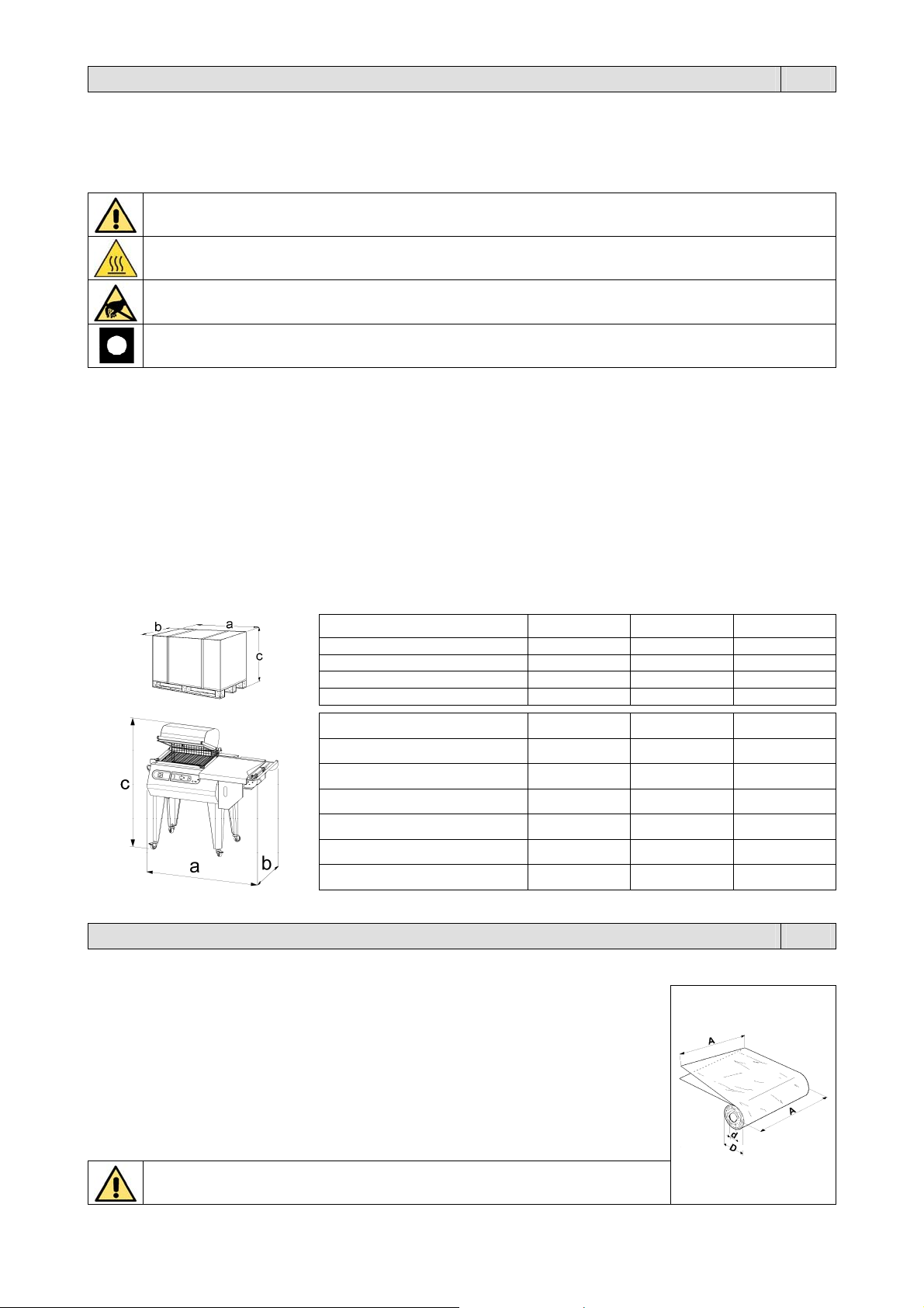
Kapitel 1. Beschreibung DE
1.1. Vorwort
Das vorliegende Handbuch wurde gemäß den Norm UNI 10893 von Juli 2000 verfasst. Es richtet sich an alle Benutzer und dient zur
korrekten Bedienung der Maschine. Bewahren Sie es an einem leicht zugänglichen Ort in der Nähe der Maschine auf, der allen
Benutzern bekannt ist. Das vorliegende Handbuch ist in Bezug auf die Sicherheit ein wesentlicher Teil der Maschine. Zur besseren
Verständlichkeit werden die verwendeten Symbole hier in der Folge erläutert.
Alle Rechte des vorliegenden Handbuchs sind dem Hersteller vorbehalten. Die Vervielfältigung, auch auszugsweise, ist gesetzlich
verboten. Die in diesem Handbuch enthaltenen Beschreibungen und Abbildungen sind unverbindlich. Der Hersteller behält sich vor,
jederzeit Änderungen vorzunehmen, die er als notwendig erachtet. Dieses Handbuch darf ohne schriftliche Genehmigung des
Herstellers nicht zur Einsicht an Dritte ausgehändigt werden.
ACHTUNG:
Vorschriften zum Unfallschutz für den Bediener. Diese Warnung weist auf bestehende Gefahren hin, die zu
Verletzungen des Maschinenbedieners führen können.
ACHTUNG:
Heiße Maschinenteile. Zeigt eine Verbrennungsgefahr durch heiße Maschinenteile an, die für die ausgesetzte
Person auch schwerwiegend sein kann.
ACHTUNG:
Nicht Berühren!
VORSICHT:
Weist auf die Gefahr hin, dass die Maschine bzw. deren Komponenten beschädigt werden könnten.
1.2. Eigenschaften der Maschine
Sie haben ein äußerst leistungsfähiges Gerät mit außergewöhnlichen Eigenschaften erworben, und wir danken Ihnen für die getroffene
Wahl. Dieses Verpackungssystem ist einzig in seiner Art und hat sich weltweit mit über 200000 Maschinen bewährt, die im Bereich der
Einschlag- und Verpackungstechnik in Betrieb sind.
Der Wert des technologischen Konzepts, sowie die Qualität der Einzelteile und der Materialien, die bei der Fertigung verwendet werden,
und die Endabnahme sind die beste Garantie für einen zuverlässigen Betrieb über einen langen Zeitraum hinweg.
Das Gerät kann für das gleichzeitige Schrumpfen und Schweißen der Folien verwendet werden, es kann dank seines Funktionsprinzips
aber auch nur zum Schweißen eingesetzt werden. In diesem Fall ist es möglich, die Verpackungsobjekte in lose, nicht geschrumpfte
Säcke einzuschweißen.
1.3. Technische Daten der Maschine
Breite “a”
Länge “b”
Höhe “c”
Gewicht 114Kg 123Kg 264Kg
Breite “a”
Länge “b”
Höhe “c” (geschlossene Haube)
Höhe “c” (geöffnete Haube)
Gewicht 90Kg 99Kg 212Kg
Höchstproduktion
RP40 RP55 RP85
1330mm 1330mm 2180mm
1080mm 1080mm 1040mm
880mm 880mm 1430mm
RP40 RP55 RP85
1160mm 1260mm 1950mm
700mm 810mm 1000mm
1120mm 1165mm 1180mm
1220mm 1310mm 1480mm
300 Verpackungen
pro Stunde
300 Verpackungen
pro Stunde
300 Verpackungen
pro Stunde
Kapitel 2. Merkmale der Folie DE
2.1. Zu verwendende Folien
Die Maschine kann mit allen wärmeschrumpfenden und nicht wärmeschrumpfenden Folien
mit einer Stärke von 15 bis 50 Mikron arbeiten, sowohl mit technischen Folien als auch mit
Lebensmittelfolien. Um optimale Ergebnisse zu garantieren, wird empfohlen, die von uns
vermarkteten Folien zu verwenden. Die besonderen Eigenschaften unserer Folien sind eine
Garantie für die Zuverlässigkeit, sowohl in Hinsicht auf die Übereinstimmung mit den
bestehenden Vorschriften als auch in Hinsicht auf die Sicherheit und das bestmögliche
Funktionieren unserer Maschinen.
RP40 A = 500mm MAX D = 250mm MAX d = 77mm
RP55 A = 600mm MAX D = 250mm MAX d = 77mm
RP85 A = 800mm MAX D = 300mm MAX d = 77mm
Es wird dringend dazu geraten, die technischen und Sicherheitsblätter der
verwendeten Folien durchzulesen und sich an die darin beschriebenen Vorgaben zu
halten!
28
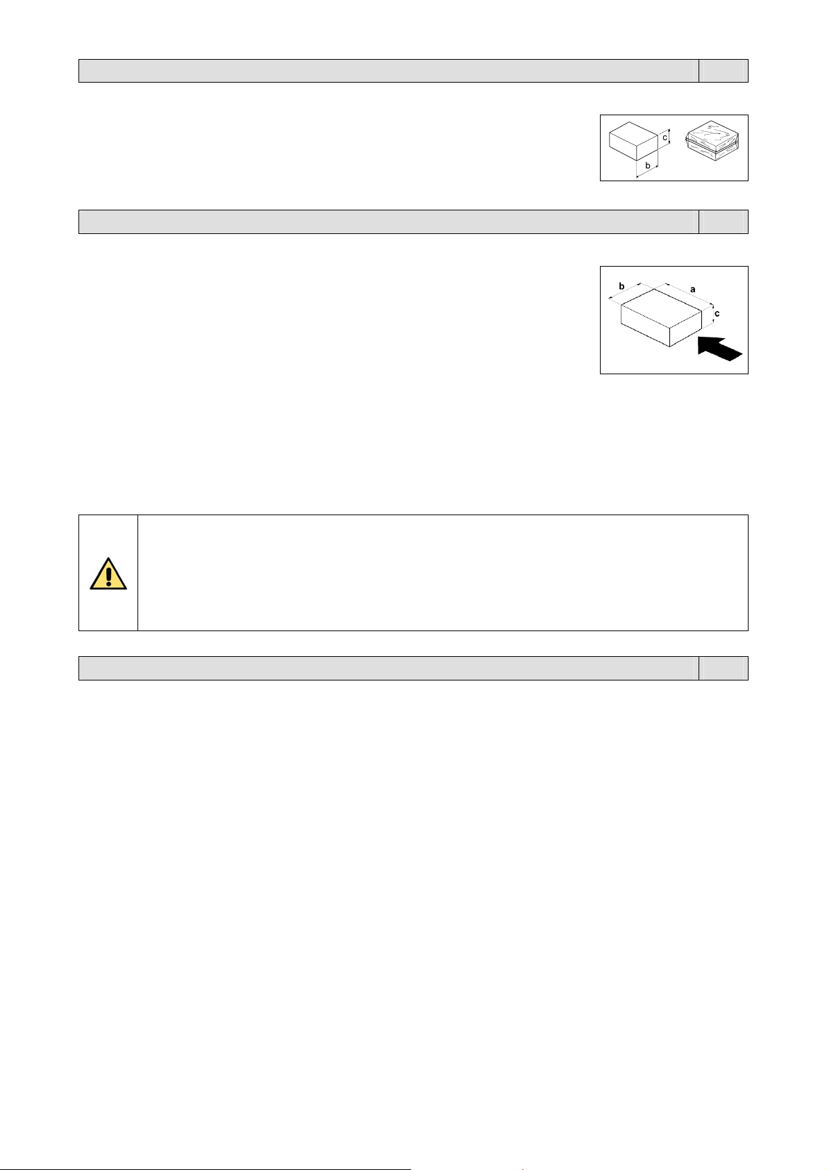
Kapitel 2. Merkmale der Folie DE
2.2. Berechnung des Bands A
Band A = b + c + 100mm
Unter Band “A” versteht man die Breite, die der Film besitzen muß, um das Produkt
verpacken zu können.
Kapitel 3. Verwendung der Maschine DE
3.1. Max. Gewicht und dimensionen der Packung
RP40 a = 400mm b = 250mm c = 160mm Gewicht = 10Kg
RP55 a = 500mm b = 380mm c = 200mm Gewicht = 15Kg
RP85 a = 800mm b = 500mm c = 200mm Gewicht = 18Kg
Hinweis: Die in der Tabelle angegebenen Maβe beziehen sich auf die max. Größe der
einzelnen Packung. Was die Höchstmaße der Packung (b x c) betrifft, beziehen Sie sich
bitte in jedem Fall auf das Kapitel 2.2., aus dem hervorgeht, dass die Summe von (b + c)
gleich der Breite der Folienspule – 100mm ist.
3.2. Was verpackt werden kann
Diese Maschinen können für die Verpackung einer umfangreichen Palette vollkommen unterschiedlicher Produkte
verwendet werden und werden erfolgreich in folgenden Bereichen eingesetzt: Lebensmittel, Handel, graphisches
Gewerbe und Versand, Großhandel, Industrie, Textilsektor.
3.3. Was nicht verpackt werden darf
Um die Maschine nicht dauerhaft zu beschädigen und Unfallrisiken für den Bediener zu vermeiden, ist es absolut
verboten, die folgenden Arten von Produkten zu verpacken:
Nasse und instabile Produkte
Flüssigkeiten jeder Art und Dichte in zerbrechlichen Behältern
Entflammbare und explosive Produkte
Spraydosen mit Treibgas bzw. jeder sonstigen Art
Loses Pulver oder staubförmige Produkte
Lose Produkte, die Kleiner als die Maschen des Haltegitters sind, Andere, hier nicht aufgezählte
Sonstige, hier nicht aufgezählte Produkte oder Materialen, die auf irgendeine Weise das Gerät
beschädigen oder den Bediener in Gefahr bringen könnten.
Kapitel 4. Sicherheitsvorschriften DE
4.1. Warnungen
Es ist sehr wichtig, dieses Kapitel vollständig und genau durchzulesen, da es wichtige Informationen über die Gefahren
enthält, denen der Bediener ausgesetzt ist, falls er die Maschine falsch anwendet. Diese grundlegenden Vorschriften
müssen zusätzlich zu denjenigen angewandt werden, die in den Ländern gelten, in denen die Maschine eingebaut wird.
Die Installation der Maschine muss durch geschultes und autorisiertes.
Die Maschine ist nicht dazu bestimmt, von Personen (einschließlich Kindern) angewandt zu werden, deren
körperliche, mentale oder Sinnesfähigkeiten eingeschränkt sind, oder die zu wenig Erfahrung oder Kenntnisse
haben, außer wenn sie durch eine Person, die für ihre Sicherheit verantwortlich ist, überwacht werden oder von
dieser Anweisungen über den Gebrauch des Geräts erhalten.
Kinder müssen ständig überwacht werden, um sicherzustellen, dass sie nicht mit der Maschine spielen.
Verwenden Sie die Maschine zu keinen anderen Zwecken als denen, die im Verkaufsvertrag angegeben sind.
Erlauben Sie keinem unbefugten Personal, die Maschine zu reparieren oder irgendwelche sonstigen Eingriffe daran
vorzunehmen.
Der Bediener muss die Warnungen, die ihn betreffen, kennen, und muss von der verantwortlichen Person für die
Abteilung immer über die Gefahren seiner Arbeit informiert werden.
Achten Sie darauf, dass die Ärmel der Arbeitsbekleidung eng am Handgelenk anliegen und knöpfen Sie sie sicher zu.
Achten Sie auf den Arbeitsbereich und die Durchgänge um die Maschine herum: sie müssen frei von Hindernissen,
sauber und angemessen beleuchtet sein.
Beheben oder entfernen Sie jede Gefahr für die Sicherheit, bevor Sie die Maschine gebrauchen und informieren Sie
die verantwortliche Person für die Abteilung immer über jede Unregelmäßigkeit beim Betrieb.
Wenden Sie die Maschine nicht an, wenn sie eine Störung hat.
Es ist verboten, Veränderungen an den Sicherheitsvorrichtungen und –kreisen vorzunehmen.
Es ist verboten, ohne Erlaubnis des Herstellers Änderungen an der Maschine vorzunehmen.
Wenn das Stromversorgungskabel beschädigt ist, muss es vom Hersteller oder von dessen Kundendienst
ausgewechselt werden, oder zumindest von einer Person mit gleichwertiger Qualifikation, um jegliche Gefahr zu
meiden.
29
 Loading...