

mininavident DENACAM User Manual

USER MANUAL
VERSION 1.2

CONTACT INFORMATION
CONTACT INFORMATION
Manufacturer’s address
mininavident AG
Hochbergerstrasse 60c
4057 Basel
Switzerland
www.mininavident.com
info@mininavident.com
Authorized service partners
mininavident’s authorized service partners cover all
service needs for the entire system life cycle.
To find your local authorized service partner visit our
website:
www.mininavident.com/servicepartner
Ordering components
INTENDED USE OF THE DENACAM SYSTEM
The DENACAM navigation system is a real-time
computerized navigational system intended to provide
assistance in the intra-operative surgical phases of dental
implantation surgery.
The system provides precise navigational guidance of
surgical instruments according to the preoperative
planning in the dental implantation procedure.
Patient population
Partially edentulous and edentulous adult and geriatric
patients who require dental implants as part of their
treatment plan.
Intended user
Oral surgeons, cranio maxillofacial surgeons, and general
practitioners with knowledge of dental implant surgery
and preoperative planning software, who understand
written and spoken English, and who have successfully
completed training on the DENACAM System.
Only use original accessories and spare parts. Order
DENACAM components from an authorized mininavident
service partner.
For order information, see "Reference numbers" on page 90
FAQ
www.mininavident.com/faq
Anatomical location
Complete upper and lower jaw, depending on the
individual mouth opening and the placement and line of
sight of the marker.
Intended medical indication
All dental implantations are indications for using this
navigation system.
DENACAM System | User Manual | REF M1000-1001 I Version 1.22

INTENDED USE OF THE DENACAM SYSTEM
Intended medical contraindication
All contraindications for dental implants apply as well as
a contraindication for this navigation system.
Dental implants contraindications
General:
Serious internal medical problems, bone metabolism
disturbances, uncontrolled bleeding disorders,
inadequate wound healing capacity, poor oral hygiene,
maxillary and mandibular growth not completed, poor
general state of health, uncooperative, unmotivated
patient, drug or alcohol abuse, psychoses, prolonged
therapy-resistant functional disorders, xerostomia,
weakened immune system, illness requiring periodic use
of steroids, titanium allergy, uncontrollable endocrine
disorders.
Relative contraindications:
Previously irritated bone, diabetes mellitus,
anticoagulation drugs/hemorrhagic diatheses, bruxism,
parafunctional habits, unfavorable anatomic bone
conditions, tobacco abuse, uncontrolled periodontitis,
temporomandibular joint disorders, treatable pathologic
diseases of the jaw and changes in the oral mucosa,
pregnancy, inadequate oral hygiene.
Electromagnetic compatibility (EMC)
The DENACAM System is a medical device that requires
special safety precautions and must be installed and
placed in operation in accordance with the attached EMC
information.
mininavident only guarantees compliance of the
DENACAM System with the EMC directives when it is
used with original spare parts, consumables, and
accessories. The use of spare parts, consumables, and
accessories that have not been approved by mininavident
may lead to increased emission of electromagnetic
interference or to reduced resistance to electromagnetic
interference.
For more information about the EMC manufacturer’s declaration,
see "EMC manufacturer’s declaration for the DENACAM System" on
page 94
Local contraindications:
Inadequate bone volume or quality, local root remnants.
Navigation system contraindications
Heavy artefacts in region of marker, preventing
unambiguous detection.
DENACAM System | User Manual | REF M1000-1001 I Version 1.2 3

NOTES ON THE USER MANUAL
NOTES ON THE USER MANUAL
General information on the User Manual
Table 1 Revision history
Publication version Software version Revision date Change description
1.0 1.0.0 August 2017 First version
1.1 1.0.0 January 2018 Additional information about the
precision of the optical system
1.2 1.1.0 July 2018 Software update. Minor content
changes
Edition notice
This User Manual is intended for operators of the
DENACAM System.
Every effort has been made to ensure that all the
information contained in this User Manual is correct at the
time of publishing. However, mininavident may need to
update the User Manual information as a result of product
surveillance.
Observe the User Manual information
Please familiarize yourself with the unit by reading
through this User Manual before putting it into operation.
It is essential that you comply with the specified warning
and safety information.
For more information about safety, see "Safety information" on
page 9
Keep the User Manual safe
Always keep the User Manual handy in case you or
another user requires information later. Save the User
Manual on the computer or print it out. If you sell the unit,
make sure that the User Manual is included with it either
as a hard copy or on an electronic storage device so that
the new owner can familiarize himself with its functions
and the specified warning and safety information.
From there, you can download this User Manual along
with other documents.
Help
If you continue to have difficulties despite having
thoroughly studied the User Manual, please contact an
authorized service partner.
For information about your local authorized service partner, see
"Authorized service partners" on page 2
Other valid documents
Documents Supplement of
Quick Start Guide DENACAM
®
System
Equipment options
This document describes the full version of the DENACAM
System. It may therefore cover components that are not
included in the package you purchased.
Online portal for technical documents
mininavident has set up an online portal for the technical
documents at http://www.mininavident.com/manuals.
DENACAM System | User Manual | REF M1000-1001 I Version 1.24
NOTES ON THE USER MANUAL
Names, symbols, and abbreviations
Component names Symbols used on components
Component name Descriptor
DENACAM
DENAOPT
DENACOMP
DENASOFT
DENASCREEN
DENADAPT
DENAREG
DENACART
DENAMARK
DENATRAY
®
System System
®
®
®
®
®
®
®
®
®
Camera
Computer
Software
Touchscreen
Adapter
Registration tool
System cart
Marker
Tray
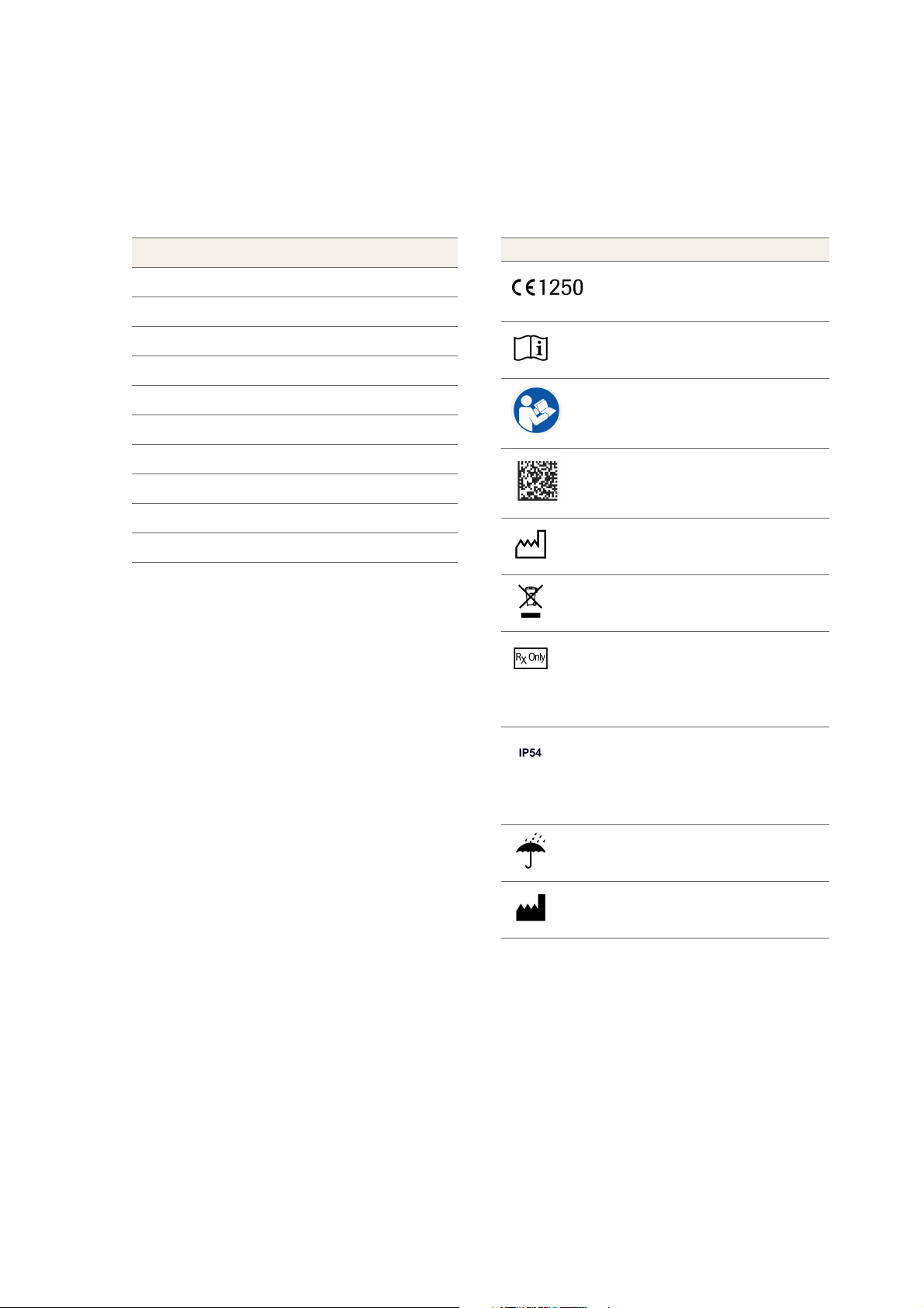
Symbol Explanation
CE mark
with identification number of the notified
body
Consult instructions for use
Consult User Manual
Data matrix code for product information
including UDI
Date of manufacture
Do not dispose of with domestic waste
Federal law restricts this system to sale by
or on the order of a dentist, physician or
any other practitioner licensed by the law
of the state in which he or she practices to
use or order the use of the system.
Limited protection against dust ingress
(no harmful deposit).
Protected against low pressure water jets
from any direction. Limited ingress
permitted.
Keep dry
Manufacturer
DENACAM System | User Manual | REF M1000-1001 I Version 1.2 5
WARRANTY AND LIABILITY
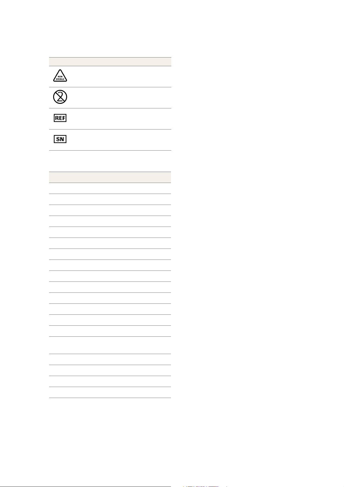
Symbol Explanation
Non sterile
Not for re-use
Reference number
Serial number
Abbreviations
Abbreviation Definition
3D Three-dimensional
AC Alternating current
ANSI American National Standards Institute
CBCT Cone beam computed tomography
DC Direct current
DIN Deutsches Institut für Normung
WARRANTY AND LIABILITY
Care and cleaning
The owner is responsible for making sure that all care and
cleaning activities are performed.
Repair
As manufacturers of medical electrical equipment,
mininavident can assume responsibility for the safety
properties of the system only if repairs on the system are
performed by authorized service partners, and if
components of the system are replaced only by original
spare parts in case of failure.
Exclusion of liability
Any customer modification of the system renders the
warranty or service agreement null and void.
In the event that the system owner fails to fulfill its
obligation to perform care and cleaning activities or
ignores error messages, mininavident and its authorized
dealers cannot assume liability for any damage thus
incurred.
EMC Electromagnetic compatibility
EN European standard
ESD Electrostatic discharge
FAQ Frequently asked questions
HDMI High-definition multimedia interface
HF High frequency
IEC International Electrotechnical Commission
IFU Instructions for use
ISO International Organization for
Standardization
LED Light emitting diode
RF Radio frequency
UDI Unique device identification
USB Universal serial bus
Duration
mininavident grants a product warranty of 24 months
from the date of purchase.
DENACAM System | User Manual | REF M1000-1001 I Version 1.26
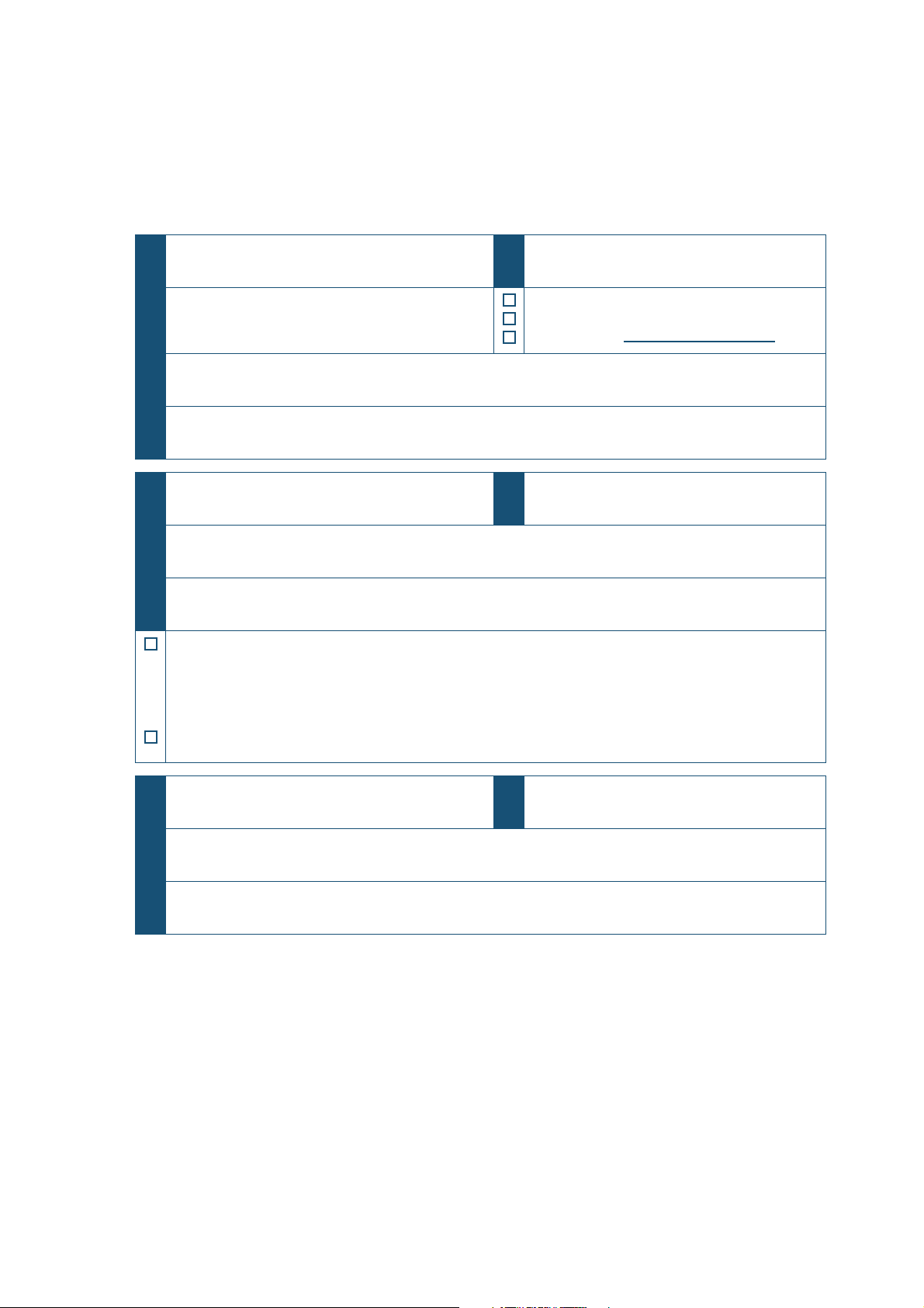
ACCEPTANCE PROTOCOL / TRAINING
Product name:
DENACAM® System
Serial number (SN):
The product is:
Purchased
Rented
Loaned until:
Manufacturer (incl. address):
mininavident, Hochbergerstrasse 60c, 4057 Basel, Switzerland
Distributor (incl. address):
Name of user: Date of birth and/or personnel number:
Hospital / practice / departement (incl. address):
Signature of user:
The signature confirms that the user has been successfully trained on the DENACAM system, in
accordance with the legal regulations (medical devices marketing regulation, medical devices act) and has
understood the content of this manual. Particular attention has been paid to the chapter of safety notes,
operation, care, and cleaning.
The signature confirms the hand over of the the fully functional DENACAM system.
Name of instructor / authorized service partner Date of instruction / handover
Address of instructor / authorized service partner
Signature of instructor / authorized service partner
ACCEPTANCE PROTOCOL / TRAINING
DENACAM System | User Manual | REF M1000-1001 I Version 1.2 7

ACCEPTANCE PROTOCOL / TRAINING
DENACAM System | User Manual | REF M1000-1001 I Version 1.28

SAFETY INFORMATION
General . . . . . . . . . . . . . . . . . . . . . . . . . . . . . . . . . . . 10
Safety classifications . . . . . . . . . . . . . . . . . . . . 10
Safety messages. . . . . . . . . . . . . . . . . . . . . . . . . . . . 11
Safety precautions . . . . . . . . . . . . . . . . . . . . . . 11
Warning messages . . . . . . . . . . . . . . . . . . . . . . 12
Caution messages. . . . . . . . . . . . . . . . . . . . . . . 13
Notices . . . . . . . . . . . . . . . . . . . . . . . . . . . . . . . 14
Safety labels on the components. . . . . . . . . . . . . . . . 15
SAFETY INFORMATION
Warning
Caution
Notice
GENERAL
GENERAL
General attention
To avoid serious or fatal injury, read this User Manual
thoroughly before you use the system and its
components.
• Pay particular attention to all safety precautions.
• Always follow the instructions in this User Manual.
• Do not use the system in a way that is not described
in this User Manual.
• Keep this User Manual in a safe place to ensure that
it is not damaged and remains available for use.
• This User Manual must always be easily accessible.
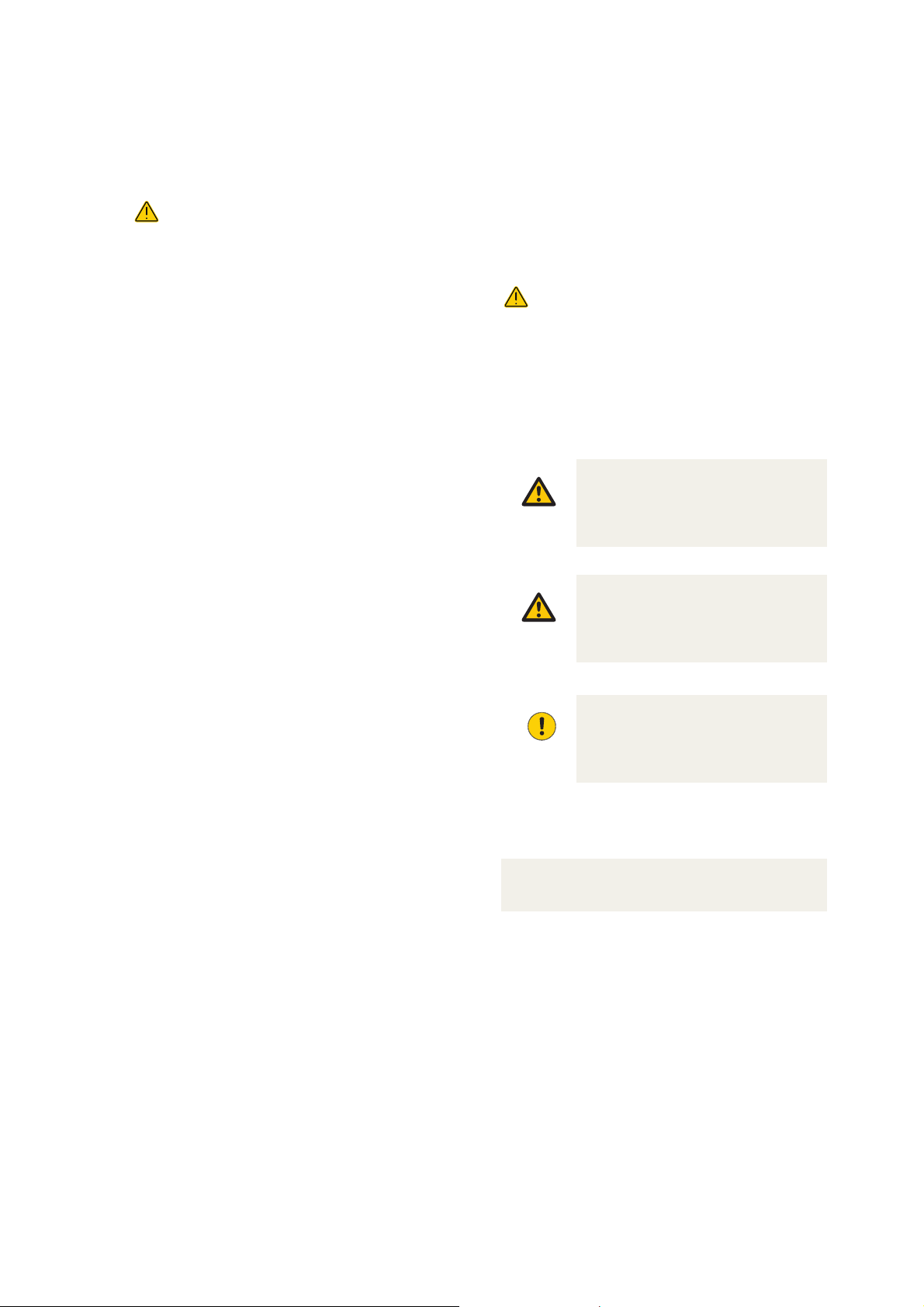
Safety classifications
The safety precautions and important user notes are
classified according to the ANSI Z535.6-2011 standard.
Familiarize yourself with the following meanings and
icons:
Safety alert
The safety alert symbol is used to alert you to
potential physical injury hazards. Comply with all
safety messages that follow this symbol to avoid
possible damage to the system, injury, or death.
These symbols and signal words are used for specific
hazards:
Warning...
...indicates a hazardous situation which, if not
avoided, could result in death or serious injury.
Caution...
...indicates a hazardous situation which, if not
avoided, could result in minor or moderate
injury.
Notice...
...indicates a hazardous situation that, if not
avoided, may result in damage to the system or
components.
Important information that is not safety relevant is
indicated with the following icon:
Note
Indicates additional information on correct use or useful tips.
DENACAM System | User Manual | REF M1000-1001 I Version 1.210

SAFETY INFORMATION
SAFETY MESSAGES
SAFETY MESSAGES
Safety precautions
To avoid serious or fatal injury, read and comply
with the following safety precautions.
ON-SITE INSTALLATION
• Only an authorized mininavident service partner
shall install the system.
• The installation must have been performed
according to the requirements of mininavident.
For more information about the installation, see "Installation and
setup" on page 29
EXCHANGE OR REMOVAL OF PARTS
Unauthorized exchange or removal of system parts can
damage the system or stop it from functioning correctly.
• Do not exchange or remove any part of the system
not specified in the user documentation.
• Leave replacement of components to an authorized
mininavident service partner.
NON-SPECIFIED ACCESSORIES AND CONSUMABLES
Use of non-specified accessories and/or consumables
can lead to incorrect navigation.
• Do not use components, accessories, or
consumables that are not intended for use with the
system.
For a list of supported materials, see "Overview of the system
components" on page 19
UNSUITABLE OPERATING CONDITIONS
Operation outside of the specified ranges may lead to
incorrect navigation or malfunction of the system.
• Use the system indoors only, and avoid heat and
humidity outside of the specified range.
• Keep the User Manual undamaged and available for
use. It must be easily accessible for all users.
UNAUTHORIZED ACCESS
Unauthorized access to the components of the system
can result in data loss, system damage, or system
unavailability.
• Only authorized persons may access system
components.
TOUCHSCREEN
The touchscreen is equipped with touch-sensitive control
technology. Operating with pointed objects such as
ballpoint pens, pencils, etc. could damage or scratch its
surface.
• Always operate the touchscreen by pressing it
gently with your fingertip.
ELECTROMAGNETIC COMPATIBILITY
Medical electrical equipment is subject to special
precautionary measures with regard to electromagnetic
compatibility (EMC).
• The installation must have been performed
according to the requirements of The installation
must have been performed according to the
requirements of mininavident.
• The use of spare parts, consumables, and
accessories that have not been approved by
mininavident may lead to increased emission of
electromagnetic interference or to reduced
resistance to electromagnetic interference.
• Operate the product in a place with a maximum
distance to electrical and magnetic interfering
transmitters. If it is necessary to operate the product
close to other devices or in a stack with other
devices, observe the correct functioning of the
system.
• HF surgical equipment can influence the operation
of the system and may not be operated in
combination with the system.
• Portable wireless communications equipment such
as wireless home network devices, mobile phones,
cordless telephones and their base stations, walkietalkie etc. can affect the system and should be kept
at least a distance of 30 cm away from any part of
the system.
DENACAM System | User Manual | REF M1000-1001 I Version 1.2 11

SAFETY INFORMATION
SAFETY MESSAGES
For more information about the EMC manufacturer’s declaration,
see "EMC manufacturer’s declaration for the DENACAM System" on
page 94
ELECTROSTATIC DISCHARGE
Electrostatic discharge (ESD) from people can damage
electronic components when the components are
touched. Damaged components usually have to be
replaced. Repairs must be performed by qualified
personnel.
Measures to protect against ESD include:
• Procedures to avoid electrostatic charging via:
• Air conditioning
• Air humidification
• Conductive floor coverings
• Non-synthetic clothing
• Procedures to avoid discharging the electrostatic
charges from your own body through contact with:
• A metallic unit casing
• A larger metallic object
• Any other metal part grounded with the
protective earth
Warning messages
List of warning messages
Failure to observe warning messages may result in death
or serious injury.
• Before operating the system, read the warning
messages carefully.
OPERATOR QUALIFICATION - INSUFFICIENT KNOWLEDGE
AND SKILLS
As an operator, ensure that you know the relevant safety
precaution guidelines and standards and the information
and procedures contained in this User Manual.
• Do not carry out operation and maintenance unless
you have read and understood the information
provided in the user documentation.
• Leave installation, repair, and preventive
maintenance to an authorized mininavident service
partner.
• Carefully follow the procedures specified in the
instructions for operation and maintenance.
mininavident recommends that all persons working with
this system are made aware of the significance of the ESD
warning label.
DENACAM System | User Manual | REF M1000-1001 I Version 1.212

SAFETY INFORMATION
SAFETY MESSAGES
Caution messages
List of caution messages
Failure to observe them may result in minor or moderate
injury.
• Before operating, read the caution messages
carefully.
INJURY TO THE PATIENT DUE TO POWER INTERRUPTION
A power failure or momentary drop in voltage may stop
the navigation procedure or lead to data loss.
• Always keep case planning data available on a USB
storage device during surgery.
For information about how to proceed after a power failure, see
"Software Messages/Warnings" on page 86
INJURY TO THE PATIENT DUE TO WRONG INSTALLATION
Incorrect installation and setup of the system may lead to
injury to the patient and/or inaccurate navigation
procedure.
• Leave installation, repair, and preventive
maintenance to an authorized mininavident service
partner.
• The person assembling the system is responsible
for ensuring conformity according to e.g. Directive
93/42/EEC.
• The system must only be connected to AC mains
supply with protective earth.
• Make sure the power supply connector can be easily
unplugged in case of an emergency.
For more information about the installation, see "Installation and
setup" on page 29
INJURY TO THE PATIENT DUE TO USE OF NON-FUNCTIONAL
OR NON-CONFORM COMPONENTS
Use of damaged, contaminated, or not correctly working
components may lead to inaccurate navigation
procedure.
• Do not use USB storage devices with a separate
power supply. USB storage devices with a separate
power supply may seriously interfere with the
electrical safety of the system.
• Replace damaged components prior surgery.
• Do not use components that are contaminated.
• Do not use components that may not work correctly
(e.g. after falling down).
• Do not use components that are not intended for use
with the system.
• Do not use components that passed their service
interval.
For a list of supported materials, see "Overview of the system
components" on page 19
INJURY TO THE PATIENT DUE TO NOT SPECIFIED
TEMPERATURE CONDITIONS OF THE COMPONENTS
Distortion of camera housing in case of heating by builtin parts (e.g. LED) or an external source (solar radiation).
• Avoid heat sources close to the system and its
components. Exposure to heat may cause the
temperature inside of the components to rise.
For information about operating conditions, see "Specifications" on
page 90
For information about cooling down the system, see "To cool down
the system" on page 87
DENACAM System | User Manual | REF M1000-1001 I Version 1.2 13

SAFETY INFORMATION
SAFETY MESSAGES
Notices
List of notices
Failure to observe the notices may result in damage to the
system.
• Before operating, read the notices contained in this
summary carefully.
DAMAGE TO THE COMPONENTS DUE TO MECHANICAL
STRESS
Shock, vibration, or pressure can damage the
components of the system.
• Keep sources of vibration away from the
components.
• Do not place objects on the components.
INFECTION BY BIOHAZARDOUS WASTE
• Treat the system as biohazardous waste.
Decontamination (cleaning, disinfection, and
sterilization) is required before reuse, recycling, or
disposal of the system.
• Dispose of the system according to the local
regulations. For more information, contact your
Service representative.
DENACAM System | User Manual | REF M1000-1001 I Version 1.214
SAFETY LABELS ON THE COMPONENTS
SAFETY LABELS ON THE COMPONENTS
The system has warning labels to draw your attention to
areas of potential hazard.
The following list explains the meanings of the labels at
the locations where you find the labels.
Table 2 Safety labels on the components
Label Where to find Meaning
Computer Consult User Manual
Computer Do not dispose of with domestic waste
SAFETY INFORMATION
Non sterile The component has not been sterilized or
treated with a process during manufacturing
to eliminate potential microorganisms
Not for re-use The component must only be used with one
patient and must not be reprocessed
DENACAM System | User Manual | REF M1000-1001 I Version 1.2 15

SAFETY INFORMATION
SAFETY LABELS ON THE COMPONENTS
DENACAM System | User Manual | REF M1000-1001 I Version 1.216

SYSTEM OVERVIEW
DENACAM workflow . . . . . . . . . . . . . . . . . . . . . . . . . 18
Overview of the system components . . . . . . . . . . . . . 19
The DENAOPT camera. . . . . . . . . . . . . . . . . . . . 20
The DENADAPT adapter . . . . . . . . . . . . . . . . . . 20
The DENACOMP computer . . . . . . . . . . . . . . . . 21
The DENASCREEN touchscreen. . . . . . . . . . . . . 21
The DENAREG registration tool . . . . . . . . . . . . . 22
The DENATRAY tray . . . . . . . . . . . . . . . . . . . . . 22
The DENAMARK marker . . . . . . . . . . . . . . . . . . 23
The DENACART system cart . . . . . . . . . . . . . . . 23
Overview of the software. . . . . . . . . . . . . . . . . . . . . . 24
System and user information . . . . . . . . . . . . . . 26
SYSTEM OVERVIEW
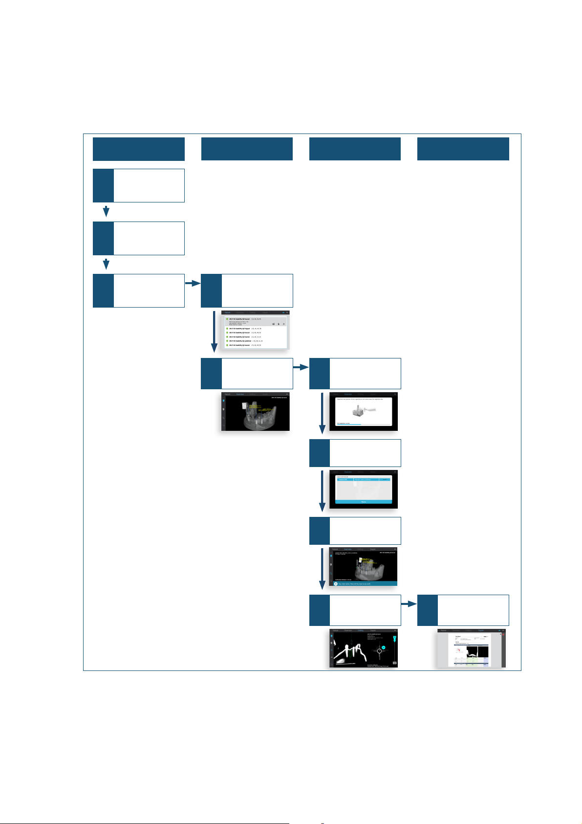
Preoperative Before surgery During surgery After surgery
1
Preparing and
positioning tray and
marker
2
Performing CBCT
scan
Case planning
3
Importing case
4
Starting up system
Loading case
5
Placing tray with
marker
Viewing 3D-scan
6
Registering round bur
or drill
7
Selecting round bur
or drill
8
Performing tray
position test
9
Guided drilling
10
Exporting case report
Shutting down
system
DENACAM WORKFLOW
DENACAM WORKFLOW
Picture 1 DENACAM workflow
For more information about operation, see "Operation" on page 41
DENACAM System | User Manual | REF M1000-1001 I Version 1.218
OVERVIEW OF THE SYSTEM COMPONENTS
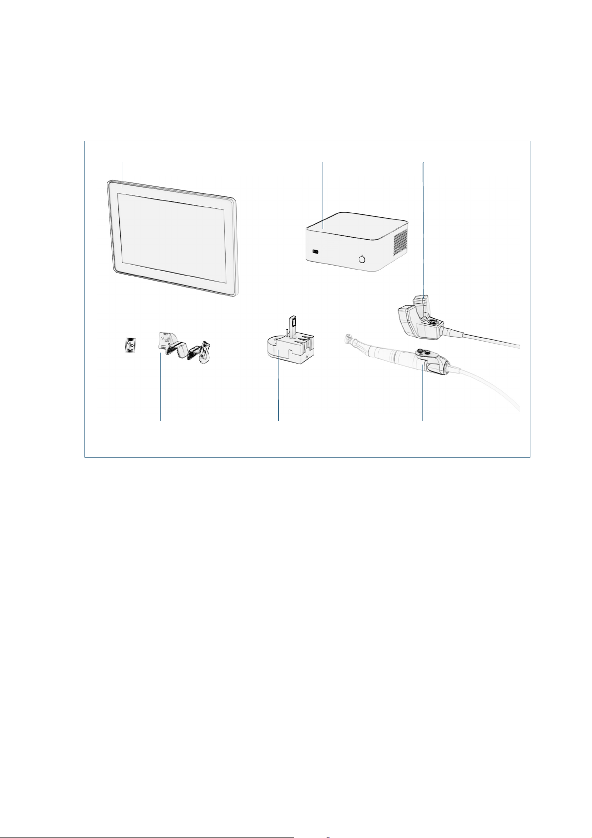
DENATOUCH touchscreen DENACOMP computer
DENAREG registration tool DENADAPT adapter
DENATRAY tray 1 and 2 with
DENAMARK marker
DENAOPT camera
SYSTEM OVERVIEW
OVERVIEW OF THE SYSTEM COMPONENTS
Picture 2 System components
For more information about unpacking the components and setting
up the system, see "Installation and setup" on page 29
For reference numbers, see "Reference numbers" on page 90
For technical specifications, see "Specifications" on page 90
DENACAM System | User Manual | REF M1000-1001 I Version 1.2 19
SYSTEM OVERVIEW
OVERVIEW OF THE SYSTEM COMPONENTS
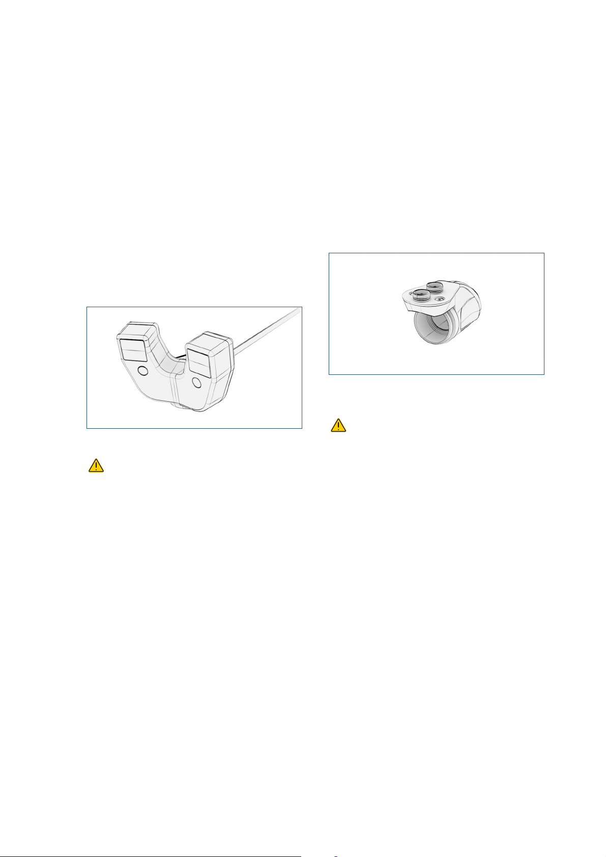
The DENAOPT camera
The camera contains the optical system (stereo camera)
which captures the pattern of the marker. In addition, two
LED lights are integrated into the housing. These LED
lights can be activated via the button in the middle of the
housing.
The camera is attached to the handpiece motor using the
adapter and connected to the computer via the USB
cable.
For information about attaching the camera o the handpiece motor,
see "Attaching the camera to the handpiece motor" on page 33
For information about connecting the camera to the computer, see
"Connecting the system" on page 32
The DENADAPT adapter
The adapter connects the camera to the handpiece motor
with a magnetic quick-release fastener. It is screwed to
the handpiece motor permanently.
For information about mounting the adapter to the handpiece motor,
see "Attaching the camera to the handpiece motor" on page 33
By means of a spring mechanism, the plate can be
rotated around the handpiece motor, allowing the camera
to be fixed in the most suitable position for drilling.
The adapter is mainly made of stainless steel and fiberreinforced plastic.
The housing is made of anodized aluminum alloy.
For cleaning, the camera must be separated from
the adapter / handpiece motor and cleaned individually.
Only wipe disinfection is allowed. The camera must not
be sterilized.
For information about cleaning, see "Individual cleaning
instructions" on page 69
Not all handpiece motors are compatible with the
adapter.
For information about compatible handpiece motors, see
www.mininavident.com/faq
The adapter is cleaned and sterilized together with the
handpiece motor.
For information about cleaning, see "Individual cleaning
instructions" on page 69
DENACAM System | User Manual | REF M1000-1001 I Version 1.220
SYSTEM OVERVIEW
OVERVIEW OF THE SYSTEM COMPONENTS
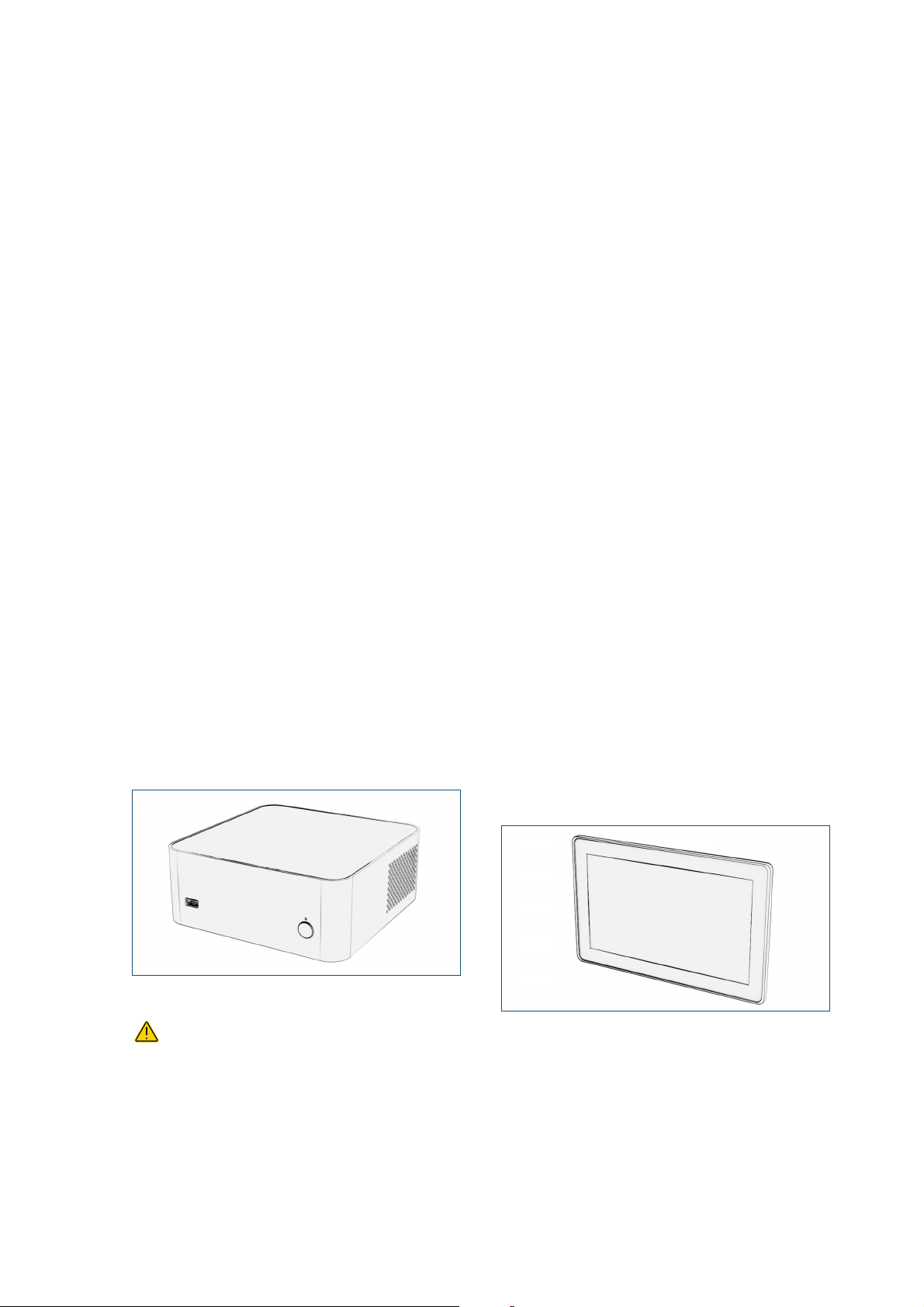
The DENACOMP computer
The computer is specially designed for the DENACAM
System using a LINUX operating system. The DENASOFT
software is pre-installed.
The computer is switched on by the power button and
switched off by the software.
The USB port on the front is used for connecting a USB
storage device for the following purpose:
• Importing case planning data
• Exporting case reports
• Updating the software
You can connect any USB storage device to the system
that does not require the installation of additional driver
software. The system can access the highest level only on
a USB storage device, i.e. the root directory. You cannot
access folders.
For information about setting up the software, see "Service tasks"
on page 35
On the back of the computer, you find the following ports:
• AC mains power input
• DC power output for the touchscreen
• USB port for the camera
• USB port for the touchscreen
• DisplayPort for the touchscreen
For information about connecting the computer to other
components, see "Connecting the system" on page 32
The DENASCREEN touchscreen
The touchscreen displays the user interface and is
equipped with a touch sensitive panel. It can be used with
gloves.
The software can be fully operated by the touchscreen.
No mouse or keyboard is necessary.
A screen protector film or sterile foil may be attached to
the touchscreen to protect it against damage or for
touching intra-operatively.
The touchscreen turns on as soon as the computer is
switched on and turns off when the computer is shut
down.
On the back of the touchscreen, you find the following
elements:
• DC power input from the computer
• USB port for the computer
• DisplayPort for the computer
• Ports not used for the DENACAM System (Audio,
VGA, DVI-D)
• Operating buttons not used for the DENACAM
System (Input, menu, plus, minus, power)
For information about connecting the touchscreen to the computer,
see "Connecting the system" on page 32
In the basic version, the touchscreen is placed on a stand.
Alternatively, it can be mounted on the swivel arm of the
DENACART system cart.
For information about mounting the touchscreen to the system cart,
see"Installing the system cart (optional)" on page 31
The surfaces of the computer are made of aluminum.
For cleaning, the computer must be switched off.
Only wipe disinfection is allowed. The computer must not
be sterilized.
For information about cleaning, see "Individual cleaning
instructions" on page 69
The surfaces of the touchscreen are made of plastic,
glass, and silicone rubber.
DENACAM System | User Manual | REF M1000-1001 I Version 1.2 21
SYSTEM OVERVIEW
OVERVIEW OF THE SYSTEM COMPONENTS
For cleaning, the computer and touchscreen must
be switched off. Only wipe disinfection is allowed. The
touchscreen must not be sterilized.
For information about cleaning, see "Individual cleaning
instructions" on page 69
The DENAREG registration tool
The registration tool is used to teach the handpiece and
to register the drill and the round bur. It consists of the
following:
• A pin for teaching the handpiece
• Three tapered slots for different drill lengths
• Two conical cavities for different round bur
diameters
• A centrally positioned marker
• A base plate, attached by a magnet
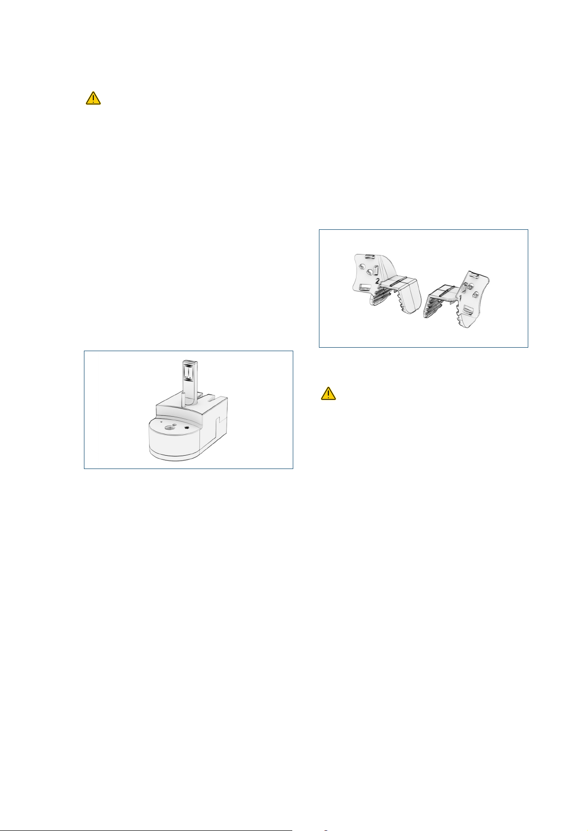
The DENATRAY tray
The tray holds the DENAMARK marker and is fixed to the
lower or upper jaw by means of impression material.
For information about handling the tray and the marker, see
"Assembling, positioning, and attaching the tray with the marker" on
page 43
It is available in two versions. Tray 1 holds the marker on
the right side, tray 2 on the left side.
The tray is made of plastic.
The registration tool is made of stainless steel and
zirconia.
The marker on the registration tool has a pattern that is
captured by the camera. The pattern may lose the
contrast after several reprocessings. Therefore,
mininavident recommends to reprocess the registration
tool no more than 50 times.
For information about cleaning and inspecting, see "Individual
cleaning instructions" on page 69
The tray is a single patient use product and must be
disposed after each patient.
For information about disposing the tray, see "To dispose the tray
after use" on page 80
DENACAM System | User Manual | REF M1000-1001 I Version 1.222
SYSTEM OVERVIEW
OVERVIEW OF THE SYSTEM COMPONENTS
The DENAMARK marker
Mounted on a tray, the marker serves as a reference point
for the navigation system in the lower or upper jaw of the
patient.
For information about mounting the marker onto the tray, see
"Assembling, positioning, and attaching the tray with the marker" on
page 43
It has a pattern that is captured by the camera.
The marker is made of aluminum oxide.
The pattern may lose the contrast after several
reprocessings. Therefore, mininavident recommends to
reprocess the marker no more than 50 times.
For information about cleaning and inspecting, see "Individual
cleaning instructions" on page 69
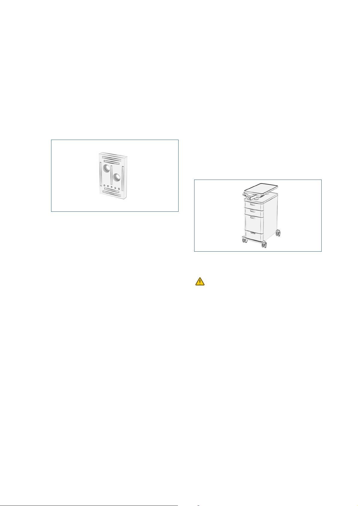
The DENACART system cart
The system cart is an accessory that can be ordered
optionally.
It offers the following possibilities for working with the
DENACAM System:
• A swivel arm for holding the touchscreen
• Storage space for the computer
• Four drawers for extra storage space
• Equipment for cable management (pre-installed
cables, holder for a magnetic multiple socket)
For information about installing the system cart, see"Setting up the
workspace" on page 49
The surfaces of the system cart are made of plastic, steel,
and aluminum.
Only wipe disinfection is allowed. The system cart
must not be sterilized.
For information about cleaning, see "Individual cleaning
instructions" on page 69
DENACAM System | User Manual | REF M1000-1001 I Version 1.2 23
SYSTEM OVERVIEW
1
Patient
screen
• Searching cases
• Importing and loading cases
• Deleting cases
2
Overview screen
• Viewing the case
• Checking the tray
• Registering the round bur or drill
4
Export
screen
• Viewing and exporting the case report
3
Drilling
screen
• Guided drilling
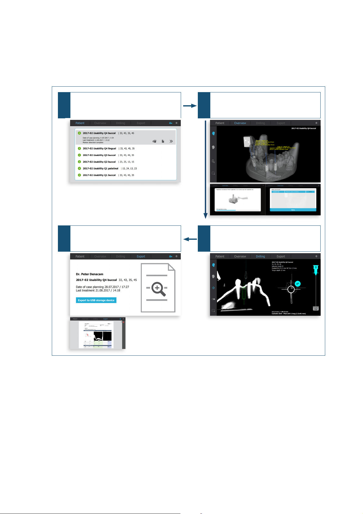
OVERVIEW OF THE SOFTWARE
OVERVIEW OF THE SOFTWARE
Picture 3 Overview user interface
The DENACAM software can be fully operated by the
touchscreen. No mouse or keyboard is necessary.
For working with the DENACAM System, the user
interface guides the user through the four main menu
entries Patient, Overview, Drilling, and Export.
Each main menu entry has its own screen, and if
necessary, additional overlays.
1. Patient screen
2. Overview screen
3. Drilling screen
4. Export screen
• Drill registration overlay
• Drill selection overlay
• Case report viewing overlay
DENACAM System | User Manual | REF M1000-1001 I Version 1.224

The DENASOFT software continuously calculates the
three-dimensional position and angle of the handpiece in
relation to the DENAMARK marker in the mouth. On the
basis of the data from the case planning, this position and
case information on the exact implant position, drill angle,
and drilling depth are displayed in real time on the
DENASCREEN touchscreen.
For information about setting up the software, see "Service tasks"
on page 35
SYSTEM OVERVIEW
OVERVIEW OF THE SOFTWARE
DENACAM System | User Manual | REF M1000-1001 I Version 1.2 25
SYSTEM OVERVIEW
OVERVIEW OF THE SOFTWARE
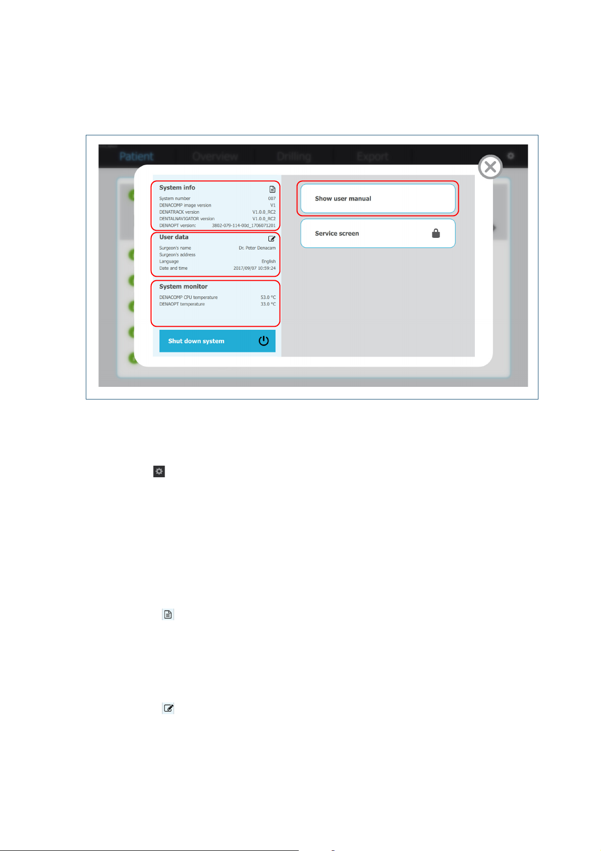
System and user information
Picture 4 System and user information - Configuration overlay
To start up the system, press the power switch on the
computer. Wait until the Patient screen is displayed.
Patient screen > button
On the configuration overlay, you have access to
following information and functions:
• System info:
• System number
• DENACOMP Image version
• DENATRACK version
• DENTALNAVIGATOR version
• DENAOPT version
• Choose the button to view the legal notice
• User data:
• Surgeon’s name
• Surgeon’s address
• Language
• Date and time
• Choose the button to edit the user data
For information about how to set up the user data, see "To set
up the user data" on page 27
•
System monitor:
• DENACOMP CPU temperature
• DENAOPT temperature
• Choose the Shut down system button to shut down
the system
• Choose the Show user manual button to view the
User Manual (pdf file)
• Choose the Service screen button to access the
service screen overlay (password required):
• LED timeout
• System check
• Handpiece teaching
• Monitoring
• Software update
• Log file export
For information about logging in to the service screen, see
"Service tasks" on page 35
DENACAM System | User Manual | REF M1000-1001 I Version 1.226
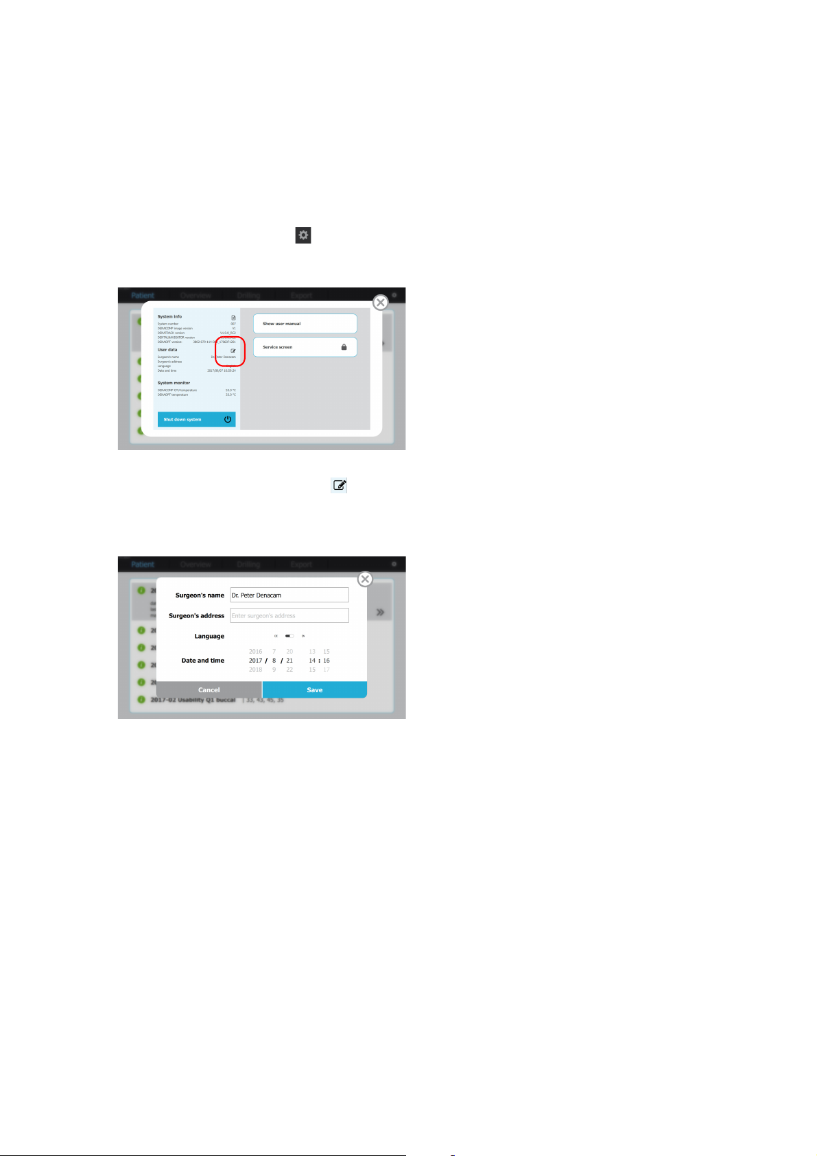
To set up the user data
1 To start up the system, press the power switch on
the computer.
Wait until the Patient screen is displayed.
2 On the menu bar, choose the button.
The configuration overlay is displayed.
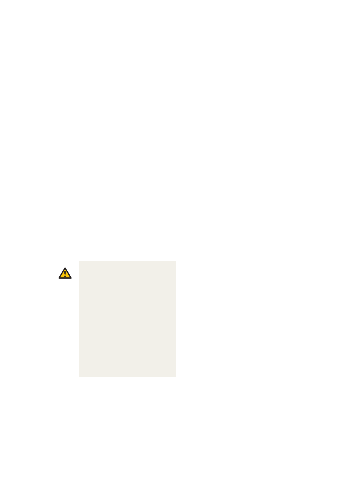
SYSTEM OVERVIEW
OVERVIEW OF THE SOFTWARE
3 To access the user data, choose the button on
the configuration overlay.
The user data overlay is displayed.
4 Edit the user data.
A virtual keyboard is displayed when you place the
cursor in an editable field.
5 Choose the Save button.
If you don’t want to save, choose the Cancel button
DENACAM System | User Manual | REF M1000-1001 I Version 1.2 27

SYSTEM OVERVIEW
OVERVIEW OF THE SOFTWARE
DENACAM System | User Manual | REF M1000-1001 I Version 1.228

INSTALLATION AND
SETUP
Unpacking and setting up the system . . . . . . . . . . . . 30
Unpacking all components . . . . . . . . . . . . . . . . 30
Contents of the packages . . . . . . . . . . . . . 30
Installing the system cart (optional). . . . . . . . . . 31
Connecting the system . . . . . . . . . . . . . . . . . . . 32
Attaching the camera to the handpiece motor . . 33
Service tasks . . . . . . . . . . . . . . . . . . . . . . . . . . 35
Teaching the handpiece . . . . . . . . . . . . . . . . . . 38
INSTALLATION AND SETUP
Caution
UNPACKING AND SETTING UP THE SYSTEM
UNPACKING AND SETTING UP THE
SYSTEM
As manufacturers of medical electrical equipment,
mininavident can assume responsibility for the safety
properties of the system only if repairs of the system are
performed by authorized service partners,
The main tasks for unpacking and setting up the system
are:
1. Unpacking all components
2. Installing the system cart (optional)
3. Connecting the system
4. Attaching the camera to the handpiece motor
5. Service tasks
6. Teaching the handpiece
PREREQUISITES
Correct transport and storage of the components.
For more information about the transport and storage conditions,
see "Transport and storage conditions" on page 92
SAFETY
Unpacking all components
Carefully unpack all components and check the
containers to make sure that all the parts are in the
package and in good condition.
Contents of the packages
For reference numbers, see "Reference numbers" on page 90
DENACART SYSTEM CART (OPTIONAL)
• 1 System cart
• 1 Swivel arm inclusive screw for mounting the
touchscreen
DENACOMP COMPUTER
• 1 Computer
• 1 AC power cable
DENASCREEN TOUCHSCREEN
• 1 Touchscreen, including stand
• 1 DC power cable
• 1 USB cable
• 1 DisplayPort cable
Injury to the patient due to wrong
installation
Incorrect installation and setup of the system
may lead to injury to the patient and/or
inaccurate navigation procedure.
• Leave installation, repair, and preventive
maintenance to an authorized mininavident
service partner.
• The person assembling the system is
responsible for ensuring conformity to
Directive 93/42/EEC.
• The system must only be connected to a
mains supply with protective earth.
• Make sure the power supply connector can
be easily unplugged in case of an
emergency.
For more information about safety, see "Safety information" on
page 9
DENAOPT CAMERA
• 1 Camera, including magnetic mounting plate
DENADAPT ADAPTER
• 1 Adapter
DENAREG REGISTRATION TOOL
• 1 Registration tool
DENATRAY TRAY 1
• 4 Tray 1
DENATRAY TRAY 2
• 4 Tray 2
DENAMARK MARKER
• 2 Markers
DENACAM QUICK START GUIDE
DENACAM System | User Manual | REF M1000-1001 I Version 1.230
 Loading...