

Minimizer B4850BTPACF, B4850BTPA Mounting Instructions
Revised 04/01/2016 Page 1
B4850BTPACF
Fender Mounting Instructions for MIN4050, MIN950 & MIN1550 Fenders
STEP 1
A. Unpack all cartons and lay out parts.
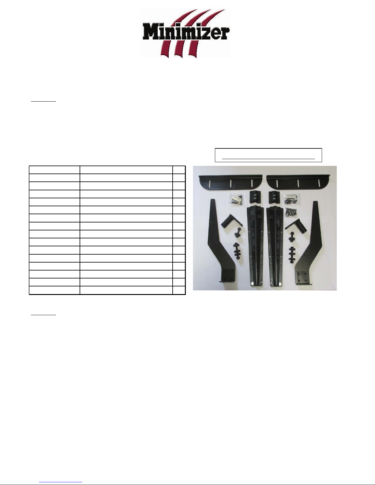
B. Compare the parts with hardware kit B4850BTPA as shown in Figure 1.
STEP 2
A. Measure the suspension travel. This measurement is used to determine the distance
between the fender and the wheel.
a. For air suspension systems, let the air out of the air bags.
b. For spring systems, measure from the stops on the springs to the bottom of the
frame.
NOTE: For air suspensions with travel exceeding 6”:
In some cases a travel stop may need to be installed to prevent such large gaps
between the fenders & tires. This will help with alignment and 5th wheel plate clearance.
(Please call Minimizer @ 800-248-3855 for questions regarding this issue).
B4850BTPACF Mounting Kit
Figure 1
PART%NUMBER DESCRIPTION QTY
PB5015 BRKT,5015,STL,SWVL,4.25,BLK 2
I62C450BFL8/RBZFT HDWR,HHCS,RBZ,FLNG,5/8-11X4.5 2
I62CNCG/RBZ HDWR,NUT,RBZ,FLNG-LOCK,5/8-11 4
PB1/2"SPACER HDWR,SPCR,PE,.5 8
PB501026CF BRKT,5010,PP,TPRD,26,CFBR 2
PBLOCK BRKT,BLOCK,PP,BLK 2
I31C300BSF/RBZ HDWR,HHCS,RBZ,SERR,5/16-18X3 8
I31C100BSF/RBZ HDWR,HHCS,RBZ,SERR,5/16-18X1 12
I31N150WFEZ HDWR,WSHR,ZINC,5/16X1.5 12
I31CNCF/RBZ HDWR,NUT,RBZ,FLNG-LOCK,5/16-18 42
PB5067 BRKT,5067,STL,CNTR,ANGL 2
I62C250BFL8/RBZ HDWR,HHCS,RBZ,FLNG,5/8-11X2.5 2
PB5069 BRKT,5069,PE,CNTR,.5 2
I31C125BSF/RBZ HDWR,HHCS,RBZ,SERR,5/16-18X1.2 22
PB5071 BRKT,5071,PE,CNTR,ANGL 2
Revised 04/01/2016 Page 2
Figure 2
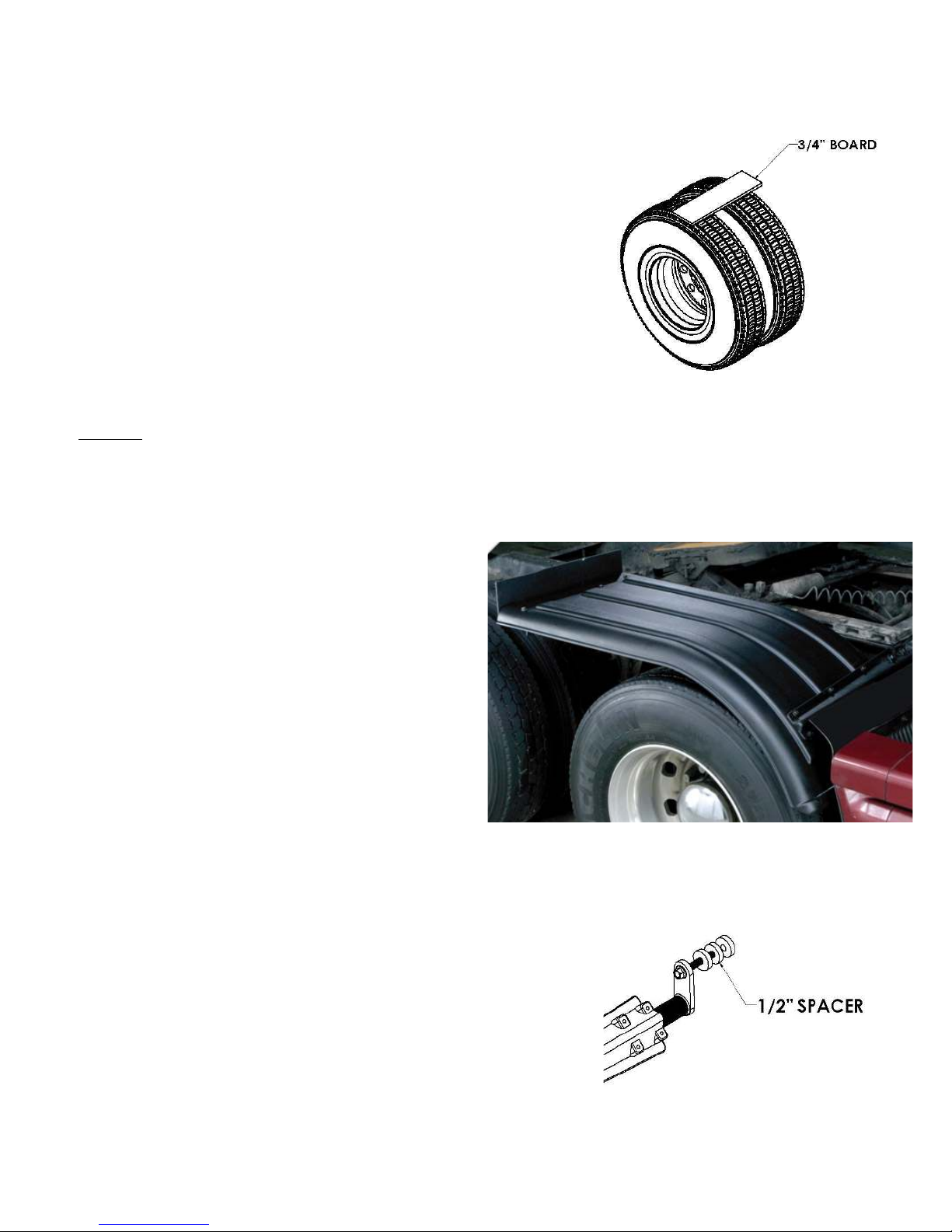
B. Gap the fenders ¾” over the maximum travel point of the suspension system. The goal is
to make sure the fender does not rub on the tire. A gap larger than ¾” may be necessary
if using worn tires.
TIP: Establish the ¾” minimum gap required in Step 2B.
a. For an air suspension system, place a ¾”
board on top of the tires after the air has
been let out of the airbags (Figure 2).
Place the fender on top of the board.
b. For a spring suspension system, add ¾”
to the measurement from Step 2A.
STEP 3
A. Position the fenders exactly where they will be mounted.
a. Visually pick and mark the locations that the brackets will bolt to the frame.
B. Try to use existing holes in the frame to
bolt through. It is possible to remove
any existing frame bolt and replace it
with the supplied bolt in the bracket kit.
a. Splash guards are available if
additional coverage is wanted
with a half fender set (Figure 3).
C. Spacers are supplied to bring the steel swivel away
from the frame in the event of any obstructions
(Figure 4).
c. The ideal setup is to mount the
steel swivel directly to the frame.
NOTE: Use spacers only when necessary.
D. Install center bracket assembly (Figure 5).
a. Try to use existing holes in the frame to bolt
Figure 4
Figure 3
 Loading...