

Minimizer B4578BTPAPL, B4578BTPA Mounting Instructions
PART NUMBER DESCRIPTION QTY
PB5015 BRKT,5015,STL,SWVL,4.25,BLK 4
I62C450BFL8/RBZFT HDWR,HHCS,RBZ,FLNG,5/8-11X4.5 4
I62CNCG/RBZ HDWR,NUT,RBZ,FLNG-LOCK,5/8-11 6
PB1/2"SPACER HDWR,SPCR,PE,.5 14
PB501026PL BRKT,5010,PP,TPRD,26,LPL 4
PBLOCK BRKT,BLOCK,PP,BLK 4
I31C300BSF HDWR,HHCS,ZINC,SERR,5/16-18X3 16
I31C100BSF HDWR,HHCS,ZINC,SERR,5/16-18X1 24
I31N150WFEZ HDWR,WSHR,ZINC,5/16X1.5 40
I31CNCFZ HDWR,NUT,FLNG-LOCK,5/16-18 54
PB5067 BRKT,5067,STL,CNTR,ANGL 2
I62C250BFL8/RBZ HDWR,HHCS,RBZ,FLNG,5/8-11X2.5 2
PB5069 BRKT,5069,PE,CNTR,.5 2
I31C125BSF/RBZ HDWR,HHCS,RBZ,SERR,5/16-18X1.2 8
I31CNCF/RBZ HDWR,NUT,RBZ,FLNG-LOCK,5/16-18 16
PB5071 BRKT,5071,PE,CNTR,ANGL 2
I31C125BSF HDWR,HHCS,ZINC,5/16-18X1.25 14
I31C100BSF/RBZ HDWR,HHCS,RBZ,SERR,5/16-18X1 8
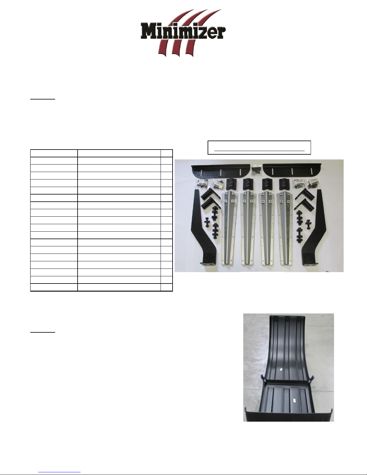
B4578BTPAPL Mounting Kit
Figure 1
Figure 2
B4578BTPAPL
Fender Mounting Instructions for MIN4000, MIN900, MIN1500 & MIN1554 Fenders
STEP 1
A. Unpack all cartons and lay out parts.
B. Compare the parts with hardware kit B4578BTPAPL as shown in Figure 1.
STEP 2
A. Lay the fenders out and clamp them together (Figure 2).
This will make bolting them together much easier.
B. Bolt the fenders together. A pack of 5/16 x 1” bolts, 5/16”
nuts and 5/16” x 1- ½” fender washers is included in the
kit. Use four bolts per joint. Recommended torque is
10-15 ft-lbs.
Revised 04/01/2016 Page 1

Figure 3
Figure 4
STEP 3
A. Measure the suspension travel. This measurement is used to determine the distance
between the fender and the wheel.
a. For air suspension systems, let the air out of the air bags.
b. For spring systems, measure from the stops on the springs to the bottom of the
frame.
NOTE: For air suspensions with travel exceeding 6”:
In some cases a travel stop may need to be installed to prevent such large gaps
between the fenders & tires. This will help with alignment and 5th wheel plate clearance.
(Please call Minimizer @ 800-248-3855 for questions regarding this issue).
B. Gap the fenders ¾” over the maximum travel point of the suspension system. The goal is
to make sure the fender does not rub on the tire. A gap larger than ¾” may be necessary
if using worn tires.
TIP: Establish the ¾” minimum gap required in Step 3B.
a. For an air suspension system, place a ¾”
board on top of the tires after the air has
been let out of the airbags (Figure 3).
Place the fender on top of the board.
b. For a spring suspension system, add ¾”
to the measurement from Step 3A.
STEP 4
A. Position the fenders exactly where they will be mounted.
a. Visually pick and mark the locations that the brackets will bolt
to the frame.
B. Try to use existing holes in the frame to bolt through. It is possible
to remove any existing frame bolt and replace it with the supplied
bolt in the bracket kit.
Tip: It is common for the front bracket to align with the
existing quarter fender holes and the rear bracket to align
with the holes left from the mud flap hanger.
NOTE: Depending on the length of the truck frame and the placement of the mud flap hangers,
the fender may tuck inside the mud flap hanger. Figure 4 shows a truck with flaps and fenders.
Revised 04/01/2016 Page 2

Figure 5
Figure 6
Figure 7
NOTE: Do not drill into the weld or any other
part of the light box. If a mud flap is mounted to
the light box style fender and the mud flap is
backed over, it may cause the interior welded
plate to become loose. Slot the mud flaps to
prevent this issue. This is NOT covered under
warranty.
See IMPORTANT assembly
instructions for center bracket
PB5069 & PB5067, last page
of this form.
C. Spacers are supplied to bring the steel swivel away
from the frame in the event of any obstructions
(Figure 5).
c. The ideal setup is to mount the
steel swivel directly to the frame.
NOTE: Use spacers only when necessary.
D. Install center bracket assembly (Figure 6).
a. Try to use existing holes in the frame to bolt through. It is possible to remove any
existing frame bolt and replace it with the supplied bolt in the bracket kit.
Recommended torque for the 5/8 x 2-1/2” bolt with washer is 110-115 ft-lbs.
E. Install center bracket as close to where the two fenders join
together as possible (Figure 7).
a. Drill three 5/16” holes through the fenders using the holes in
bracket PB5069 as a guide.
b. Use three 5/16” x 1 ¼” bolts to bolt the center bracket and
fenders together. Recommended torque for all 5/16”
Revised 04/01/2016 Page 3
hardware is 10-15 ft-lbs.
c. Use 5/16” fender washers and 5/16” nuts provided with the
kit on the inside of the fenders.
 Loading...