

Page 1

935-MP55T1-000G
12310953E-DVD
System Board
User’s Manual
Page 2

Copyright
This publication contains information that is protected by copyright. No part of it
may be reproduced in any form or by any means or used to make any transformation/adaptation without the prior written permission from the copyright holders.
This publication is provided for informational purposes only. The manufacturer
makes no representations or warranties with respect to the contents or use
of this manual and specically disclaims any express or implied warranties of
merchantability or tness for any particular purpose. The user will assume the
entire risk of the use or the results of the use of this document. Further, the
manufacturer reserves the right to revise this publication and make changes to
its contents at any time, without obligation to notify any person or entity of such
revisions or changes.
© 2009. All Rights Reserved.
Trademarks
Windows® 2000 and Windows® XP are registered trademarks of Microsoft Corporation. Award is a registered trademark of Award Software, Inc. Other trademarks
and registered trademarks of products appearing in this manual are the properties of their respective holders.
FCC and DOC Statement on Class B
This equipment has been tested and found to comply with the limits for a Class B
digital device, pursuant to Part 15 of the FCC rules. These limits are designed to
provide reasonable protection against harmful interference when the equipment
is operated in a residential installation. This equipment generates, uses and can
radiate radio frequency energy and, if not installed and used in accordance with
the instruction manual, may cause harmful interference to radio communications.
However, there is no guarantee that interference will not occur in a particular
installation. If this equipment does cause harmful interference to radio or television reception, which can be determined by turning the equipment off and on,
the user is encouraged to try to correct the interference by one or more of the
following measures:
• Reorient or relocate the receiving antenna.
• Increase the separation between the equipment and the receiver.
• Connect the equipment into an outlet on a circuit different from that to which
the receiver is connected.
• Consult the dealer or an experienced radio TV technician for help.
Notice:
1. The changes or modications not expressly approved by the party responsible
for compliance could void the user’s authority to operate the equipment.
2. Shielded interface cables must be used in order to comply with the emission
limits.
Page 3

Table of Contents
About this Manual ........................................................................................... 4
Warranty ..........................................................................................................4
Static Electricity Precautions .........................................................................5
Safety Measures ................................................................................................5
About the Package ..........................................................................................6
About the Genie BIOS Guideline ................................................................6
Before Using the System Board ...................................................................6
System Board Layout ...................................................................................... 7
English .................................................................................................................8
Français .............................................................................................................31
Deutsch ............................................................................................................54
Italiano ..............................................................................................................77
Español .......................................................................................................... 103
Polski .............................................................................................................. 126
Русский ...................................................................................................... 148
Debug LED Post and Troubleshooting .................................................. 170
Page 4

4
E
English
About this Manual
An electronic le of this manual is included in the DVD. To view the user’s manual, insert the DVD into an optical drive. The autorun screen will appear. On the
top row of the screen, click the last icon to open the Manuals menu.
For additional information on the system board, please download the complete
version of the manual from DFI’s website. Visit www.d.com.
Warranty
1. Warranty does not cover damages or failures that arised from misuse of the
product, inability to use the product, unauthorized replacement or alteration
of components and product specications.
2. The warranty is void if the product has been subjected to physical abuse,
improper installation, modication, accidents or unauthorized repair of the
product.
3. Unless otherwise instructed in this user’s manual, the user may not, under
any circumstances, attempt to perform service, adjustments or repairs on the
product, whether in or out of warranty. It must be returned to the purchase
point, factory or authorized service agency for all such work.
4. We will not be liable for any indirect, special, incidental or consequencial
damages to the product that has been modied or altered.
Page 5

5
E
English
Static Electricity Precautions
It is quite easy to inadvertently damage your PC, system board, components
or devices even before installing them in your system unit. Static electrical discharge can damage computer components without causing any signs of physical
damage. You must take extra care in handling them to ensure against electrostatic build-up.
1. To prevent electrostatic build-up, leave the system board in its anti-static bag
until you are ready to install it.
2. Wear an antistatic wrist strap.
3. Do all preparation work on a static-free surface.
4. Hold the device only by its edges. Be careful not to touch any of the components, contacts or connections.
5. Avoid touching the pins or contacts on all modules and connectors. Hold
modules or connectors by their ends.
Important:
Electrostatic discharge (ESD) can damage your processor, disk drive and
other components. Perform the upgrade instruction procedures described
at an ESD workstation only. If such a station is not available, you can
provide some ESD protection by wearing an antistatic wrist strap and
attaching it to a metal part of the system chassis. If a wrist strap is
unavailable, establish and maintain contact with the system chassis
throughout any procedures requiring ESD protection.
Safety Measures
To avoid damage to the system:
• Use the correct AC input voltage range.
To reduce the risk of electric shock:
• Unplug the power cord before removing the system chassis cover for installation or servicing. After installation or servicing, cover the system chassis
before plugging the power cord.
Battery:
• Danger of explosion if battery incorrectly replaced.
• Replace only with the same or equivalent type recommend by the manufac-
turer.
• Dispose of used batteries according to local ordinance.
Page 6

6
E
English
About the Package
The system board package contains the following items. If any of these items are
missing or damaged, please contact your dealer or sales representative for assistance.
One system board
Four Serial ATA data cables
Two Serial ATA power cables
Smart connectors
One I/O shield
One DVD
One Creative X-Fi Tool CD
One user’s manual
The system board and accessories in the package may not come similar to the
information listed above. This may differ in accordance to the sales region or
models in which it was sold. For more information about the standard package in
your region, please contact your dealer or sales representative.
About the Genie BIOS Guideline
Genie BIOS allows conguring the system to optimize system performance and
overclock capability. For detailed information about Genie BIOS, please download
the Genie BIOS Guideline from DFI’s website (www.d.com). The guideline is also
available in the provided DVD.
Before Using the System Board
Before using the system board, prepare basic system components.
If you are installing the system board in a new system, you will need at least the
following internal components.
• A CPU
• Memory module
• Storage devices such as hard disk drive, CD-ROM, etc.
You will also need external system peripherals you intend to use which will nor-
mally include at least a keyboard, a mouse and a video display monitor.
Page 7
7
E
English
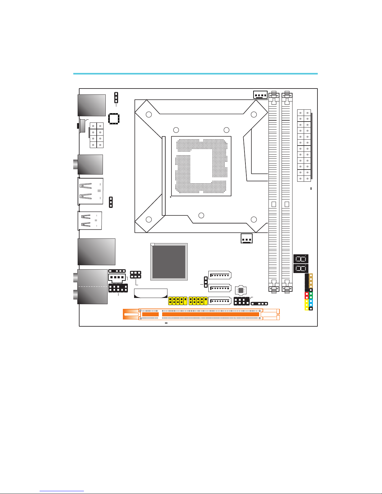
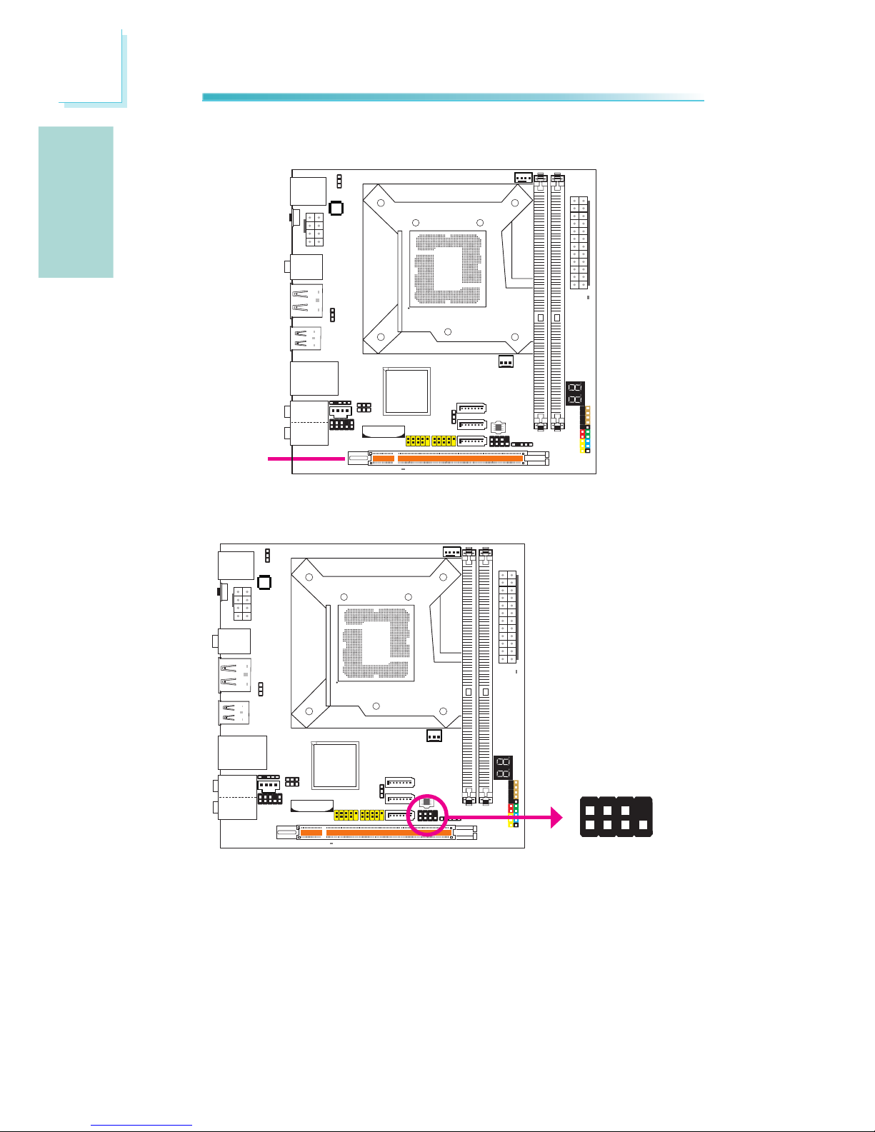
System Board Layout
LGA 1156
Mouse
KB
Clear CMOS
switch
1
4
5
8
12V power
1
PS/2 power
select (J )P8
1
CPU fan
Top: Coaxial RCA
Bottom: Optical
S/PDIF-
out
Bottom:Port shared
between PowereSATA
and USB 11
Top: USB 10
1
USB 8-13
select (JP5)
power
USB 8-9
LAN
USB 12-13
Line-in
Front R/L
Mic-in
Center/
Subwoofer
Side R/L
Rear R/L
1
S/PDIF
CD-in
1
Front audio
1
9
10
Battery
USB 0-1
2
9
10
1
2
9
10
1
USB 2-3
Clear CMOS
(JP2)
Secondary RTC
reset (JP12)
1
1
1
USB 0-3
select (JP6)
power
1
SATA 0
1
1
SATA 1
SATA 3
SPI Flash
BIOS
1
2
7
8
Download
BIOSFlash
1
IrDA
1
Front panel
2
19
HD-LED RESET
SPEAKER
PWR-LED
ATX-SW
DIMM1
DIMM 2
1
PWM fan
Intel
P55
2412
AT X
power
113
DRAM
power LED
PCIE1
Standby
power LED
PCIE 1
Standby
power LED
Page 8

8
English
E
English
Chapter 1 - Introduction
Specifications
Processor
Chipset
System Memory
Expansion Slots
BIOS
Audio
LAN
Serial ATA
Rear Panel I/O
• LGA 1156 socket for:
- Intel® Core i5/i7 Lynneld processors
• Supports Intel® Turbo Boost Technology
• Intel® P55 Express chipset
• Two 240-pin DDR3 DIMM sockets
• Supports DDR3 1600(O.C.)/1333/1066 MHz
• Supports up to 8GB system memory
• Delivers up to 21Gb/s bandwidth at 1333MHz
• Supports dual channel (128-bit wide) memory interface
• Supports non-ECC unbuffered DIMMs
• 1 PCI Express (Gen 2) x16 slot
• AMI BIOS
• 32Mbit SPI ash BIOS
• CMOS Reloaded
• Realtek ALC885 High Denition audio CODEC
• 8-channel audio output
• DAC SNR/ADC SNR of 106dB/101dB
• Full-rate lossless content protection technology
• Optical S/PDIF-out and coaxial RCA S/PDIF-out interfaces
• Intel 82578DC Gigabit Ethernet PHY
• Fully compliant to IEEE 802.3 (10BASE-T), 802.3u
(100BASE-TX) and 802.3ab (1000BASE-T) standards
• Supports up to 3 SATA devices
- Intel Matrix Storage technology
- SATA speed up to 3Gb/s
- RAID 0, RAID 1, RAID 0+1 and RAID 5
• Supports 1 Power eSATA device
• 1 mini-DIN-6 PS/2 mouse port
• 1 mini-DIN-6 PS/2 keyboard port
• 1 Clear CMOS switch
• 1 coaxial RCA S/PDIF-out port
• 1 optical S/PDIF-out port
• 1 Power eSATA port
• 6 USB 2.0/1.1 ports (one shared with Power eSATA)
• 1 RJ45 LAN port
• Center/subwoofer, rear R/L and side R/L jacks
• Line-in, line-out (front R/L) and mic-in jacks
Page 9

9
English
E
English
Internal I/O
Power
Management
Hardware
Monitor
PCB
• 2 connectors for 4 additional external USB 2.0 ports
• 1 front audio connector
• 1 CD-in connector
• 1 S/PDIF connector
• 1 IrDA connector
• 3 Serial ATA connectors
• 1 24-pin ATX power connector
• 1 8-pin 12V power connector
• 1 front panel connector
• 2 fan connectors
• 1 download ash BIOS connector
• 1 diagnostic LED
• ACPI and OS Directed Power Management
• ACPI STR (Suspend to RAM) function
• Wake-On-PS/2 KB/Mouse
• Wake-On-USB KB
• Wake-On-LAN
• RTC timer to power-on the system
• AC power failure recovery
• Monitors CPU/chipset/PWM temperature and overheat
alarm
• Monitors CPU/DRAM/VTT/CPU_PLL/+3.3/+5/+12/+5VSB/
Vbat voltages
• Monitors the speed of the cooling fans
• CPU Overheat Protection function monitors CPU tempera-
ture and fan during system boot-up - automatic shutdown
upon system overheat
• 6 layers, Mini-ITX form factor
• 17cm (6.7”) x 17cm (6.7”)
Page 10

10
English
E
English
Chapter 2 - Hardware Installation
Jumper Settings
If you encounter the following,
a) CMOS data becomes corrupted.
b) You forgot the supervisor or user password.
c) The overclocked settings in the BIOS resulted to the system’s instability or
caused system boot up problems.
you can recongure the system with the default values stored in the ROM BIOS.
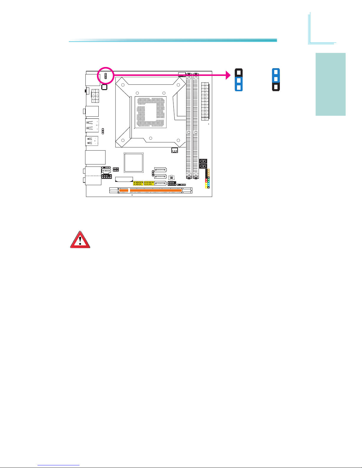
Clear CMOS Switch
The Clear CMOS switch at the rear panel of the system provides convenience by
allowing you to clear the CMOS without having to remove the chassis cover. Press
the black button to clear the CMOS data.
Clear CMOS Jumper
To load the default values stored in the ROM BIOS, please follow the steps below.
1. Power-off the system then unplug the power cord.
2. Set JP2 pins 2 and 3 to On. Wait for a few seconds and set JP2 back to its
default setting, pins 1 and 2 On.
3. Now plug the power cord then power-on the system.
Clear CMOS Data
2-3 On:
Clear CMOS Data
1-2 On: Normal
(default)
JP2
31 2
31
2
Clear CMOS
switch
Page 11
11
English
E
English
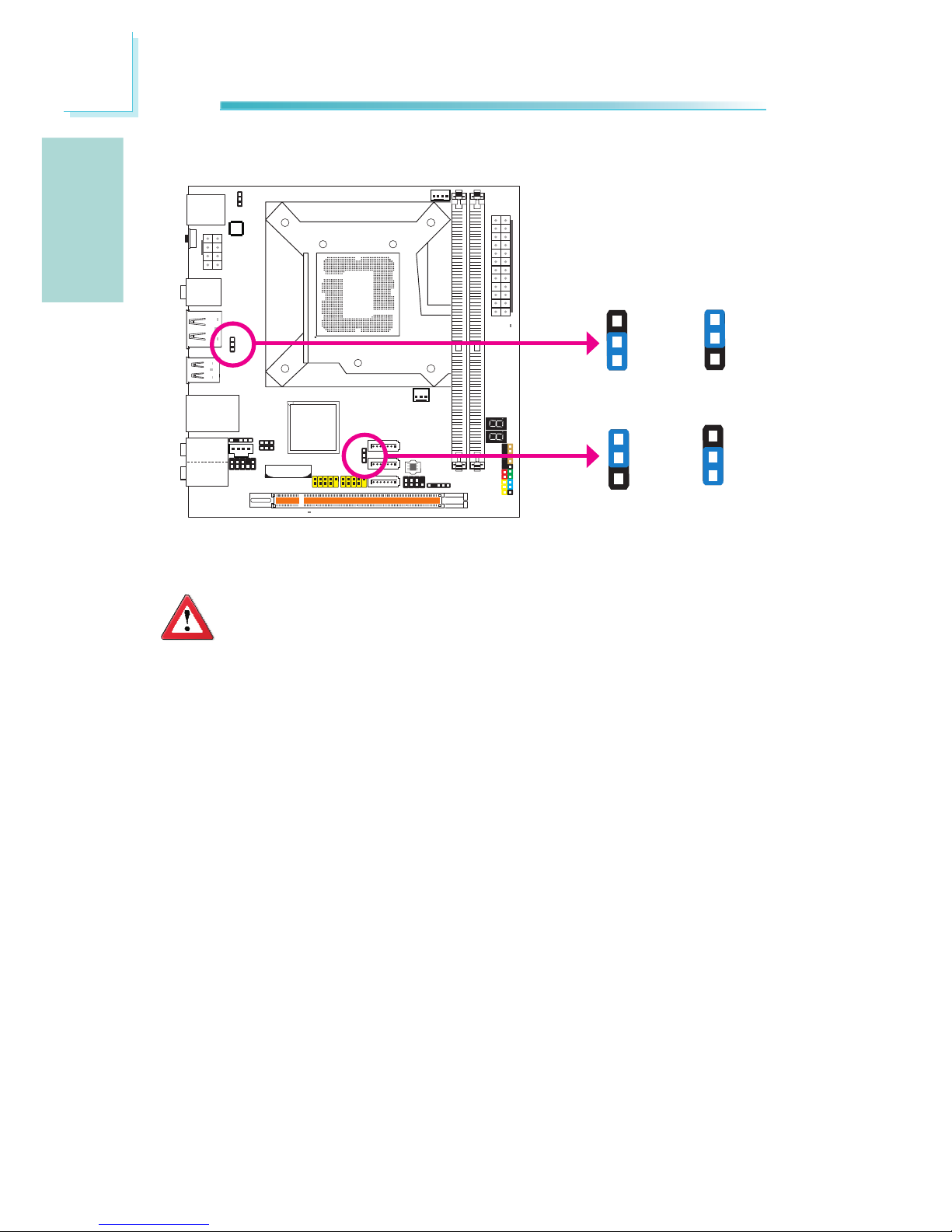
PS/2 Power Select
Selecting 5VSB will allow you to use the PS/2 keyboard or PS/2 mouse to wake
up the system.
Important:
The 5VSB power source of your power supply must support ≥720mA.
JP8
3
1
2
3
1
2
2-3 On:
5VSB
1-2 On: 5V
(default)
Page 12
12
English
E
English
USB Power Select
USB 8-13
(JP5)
Selecting 5VSB will allow you to use the USB keyboard to wake up the system.
Important:
The 5VSB power source of your power supply must support ≥1.5A (2
devices) or ≥2A (3 or more devices).
3
1
2
3
1
2
2-3 On:
5VSB
1-2 On: 5V
(default)
1
3
2
1
3
2
2-3 On:
5VSB
1-2 On: 5V
(default)
USB 0-3
(JP6)
Page 13
13
English
E
English
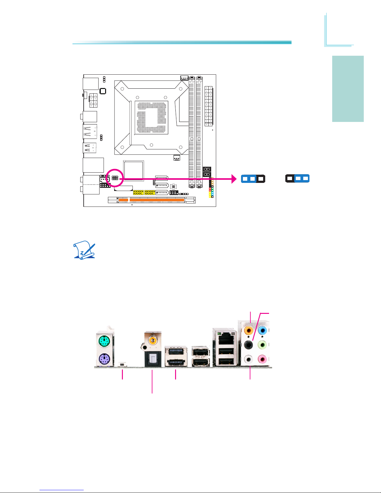
Secondary RTC Reset
When the RTC battery is removed, this jumper resets the manageability register
bits in the RTC.
Note:
1. The SRTCRST# input must always be high when all other RTC power
planes are on.
2. In the case where the RTC battery is dead or missing on the platform, the SRTCRST# pin must rise before the RSMRST# pin.
2-3 On:
RTC Reset
1-2 On: Normal
(default)
JP12
31 2
31 2
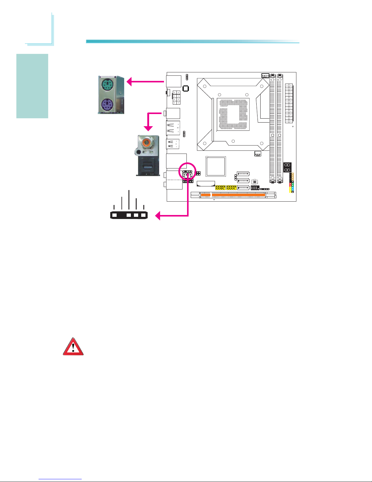
Rear Panel I/O Ports
PS/2 K/B
Clear CMOS
switch
USB 8 USB 12-13
Mic-in
Side R/L
Center/Subwoofer
Rear R/L
Line-in
Front R/L
LAN
PS/2
Mouse
USB 9
Power eSATA or
USB 11
USB 10
Optical
S/PDIF-out
Coaxial
S/PDIF-out
Page 14
14
English
E
English
PS/2 Mouse and PS/2 Keyboard Ports
These ports are used to connect a PS/2 mouse and a PS/2 keyboard.
Optical S/PDIF
The optical S/PDIF jack is used to connect an external audio output device using
an optical S/PDIF cable.
Coaxial RCA S/PDIF
The coaxial RCA S/PDIF jack is used to connect an external audio output device
using a coaxial S/PDIF cable.
Important:
DO NOT use optical S/PDIF and Coaxial RCA S/PDIF at the same time.
PS/2 Ports and S/PDIF Ports
PS/2 Mouse
PS/2 KB
Optical S/PDIF
Coaxial RCA
S/PDIF
S/PDIF Connector
The S/PDIF connector is used to connect an external S/PDIF port. Your S/PDIF
port may be mounted on a card-edge bracket. Install the card-edge bracket to
an available slot at the rear of the system chassis then connect the audio cable
to the S/PDIF connector. Make sure pin 1 of the audio cable is aligned with pin 1
of the S/PDIF connector.
S/PDIF
1 5
+5V
Key
SPDIF out
Ground
SPDIF in
Page 15
15
English
E
English
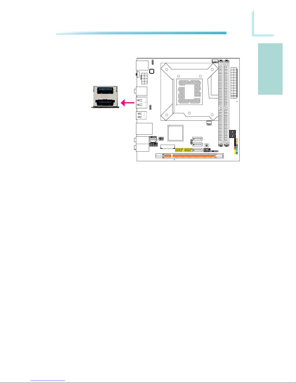
Power eSATA
Power eSATA
The arrow above points to the location shared by the Power eSATA and USB 11.
You can choose to plug a Power eSATA device or a USB device. This port supplies
sufcient power to run an eSATA device (no additional power required).
Port shared between
Power eSATA and USB 11
Page 16
16
English
E
English
USB 0-1
USB 10
LAN
USB 11 /
Power eSATA
USB 12
USB 13
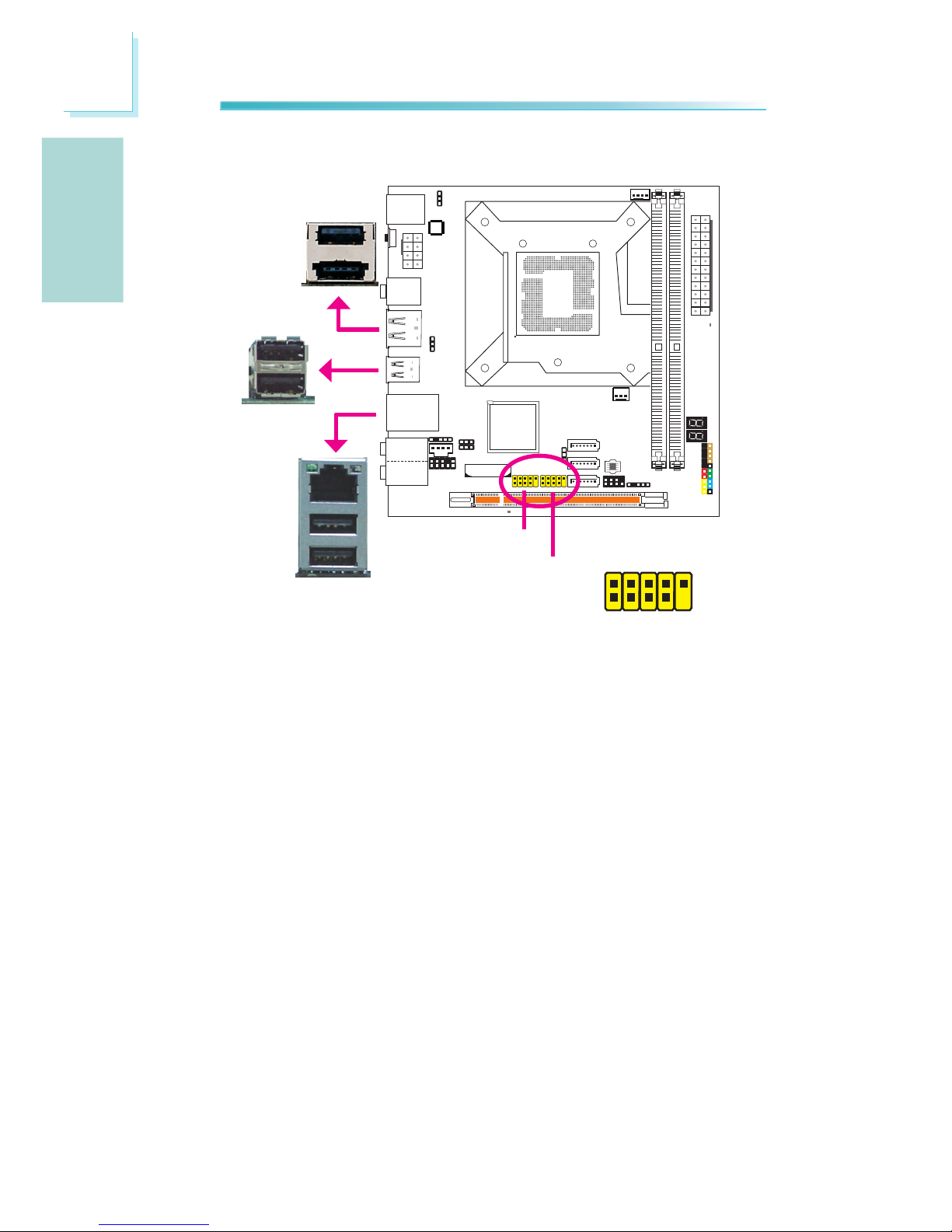
USB and LAN Ports
USB
The USB ports are used to connect USB 2.0/1.1 devices. The 10-pin connectors
allow you to connect 4 additional USB 2.0/1.1 ports. Your USB ports may come
mounted on a card-edge bracket. Install the card-edge bracket to an available
slot at the rear of the system chassis then connect the USB port cables to these
connectors.
USB 11 is a port shared with Power eSATA. If you are using a Power eSATA device, you cannot use this port to connect a USB device.
LAN
The LAN port allows the system board to connect to a local area network by
means of a network hub.
USB 2-3
1
VCC
-Data
+Data
GND
Key
VCC
-Data
+Data
GND
GND
2
10
9
USB 9
USB 8
Page 17
17
English
E
English
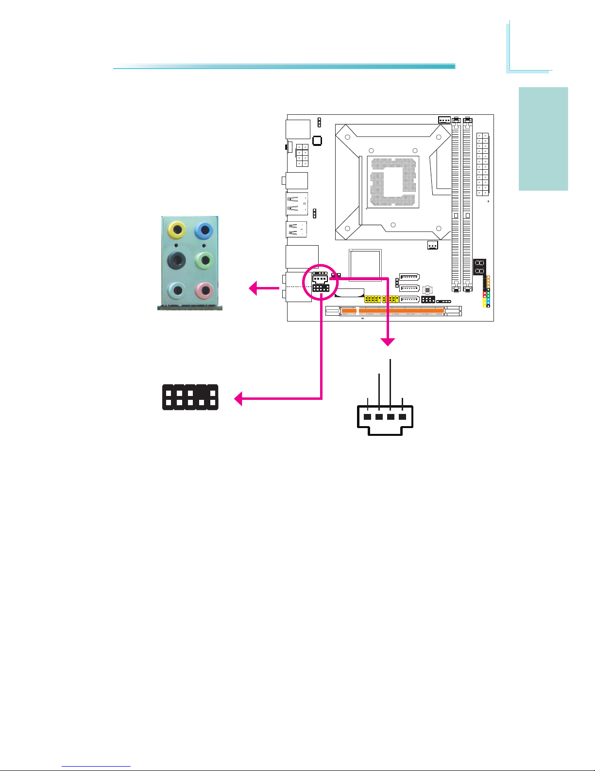
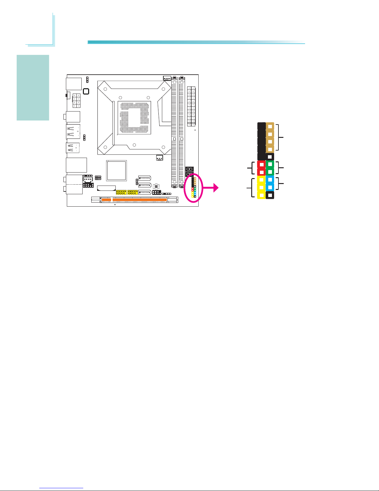
Rear Panel Audio
Center/Subwoofer Jack (Orange)•
This jack is used to connect to the center and subwoofer speakers of the au-
dio system.
Rear Right/Left Jack (Black)•
This jack is used to connect to the rear right and rear left speakers of the
audio system.
Side Right/Left Jack (Gray)•
This jack is used to connect to the side left and side right speakers of the
audio system.
Line-in (Light Blue)•
This jack is used to connect any audio devices such as Hi- set, CD player,
tape player, AM/FM radio tuner, synthesizer, etc.
Audio and CD-In
Rear audio
Front R/L
Line-in
Mic-in
Rear R/L
Center/
Subwoofer
Side R/L
CD-in
Front audio
1
Mic2-L
Line2-R
Front_IO_Sense
GND
Presence Signal
Key
2
10
Mic Jack Sense
Line-out Jack
Sense
9
Mic2-R
Line2-L
4
1
Left audio
channel
Right audio
channel
Ground
Ground
Page 18
18
English
E
English
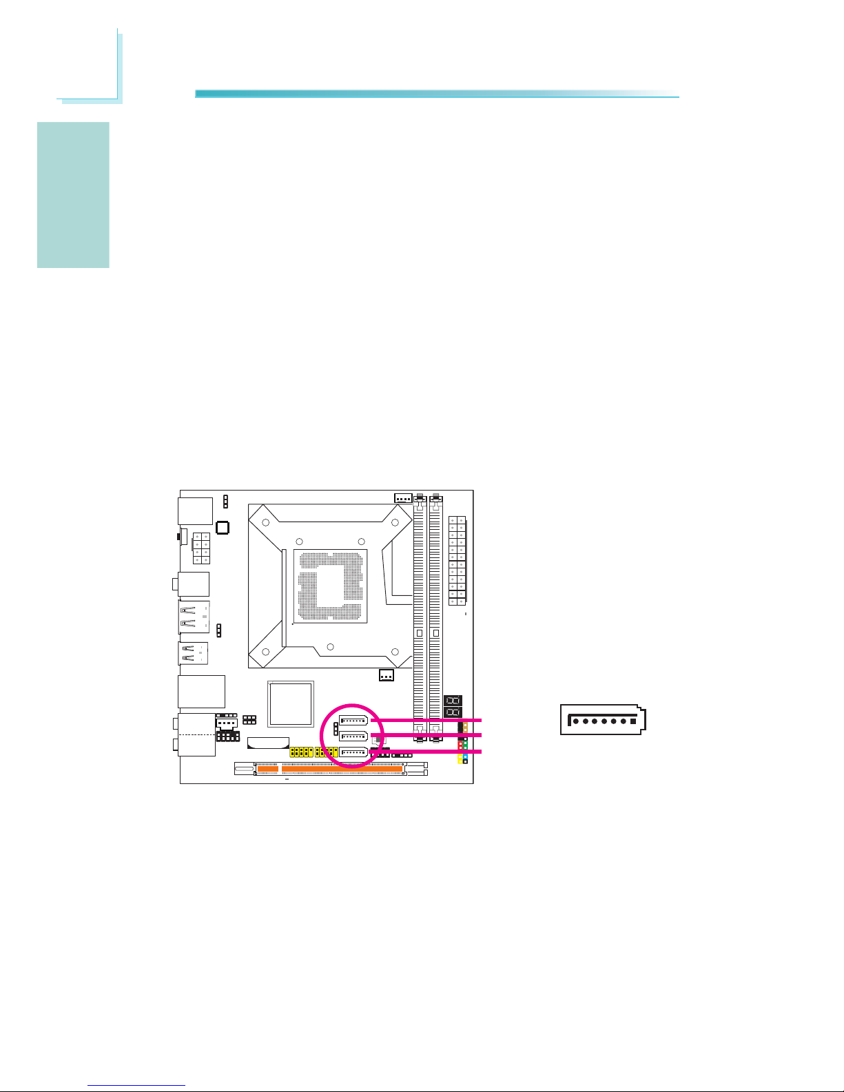
The Serial ATA (SATA) connectors are used to connect Serial ATA drives. Connect
one end of the Serial ATA cable to a Serial ATA connector and the other end to
your Serial ATA device.
Configuring RAID
Refer to the RAID chapter in this manual for more information about creating
RAID on Serial ATA drives.
Serial ATA Connectors
Line-out - Front Right/Left Jack (Lime)•
This jack is used to connect to the front right and front left speakers of the
audio system.
Mic-in Jack (Pink)•
This jack is used to connect an external microphone.
Front Audio
The front audio connector is used to connect to the line-out and mic-in jacks that
are at the front panel of your system.
CD-in
The CD-in connector is used to receive audio from a CD-ROM drive, TV tuner or
MPEG card.
Internal I/O Connectors
7
RXN
GND
TXP
TXN
GND
1
RXP
GND
SATA 0
SATA 1
SATA 3
Page 19
19
English
E
English
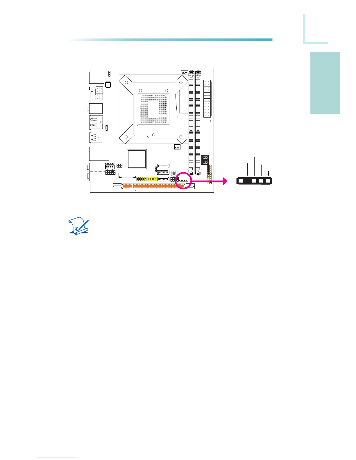
IrDA Connector
Connect the cable connector from your IrDA module to the IrDA connector.
Note:
The sequence of the pin functions on some IrDA cable may be reversed
from the pin function dened on the system board. Make sure to connect
the cable to the IrDA connector according to their pin functions.
You may need to install the proper drivers in your operating system to use the
IrDA function. Refer to your operating system’s manual or documentation for
more information.
1 5
VCC
N. C.
IRRX
Ground
IRTX
Page 20
20
English
E
English
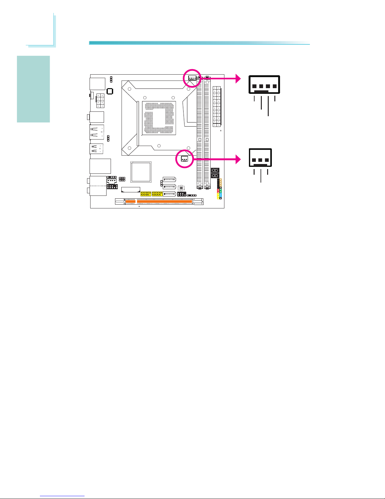
Cooling Fan Connectors
These fan connectors are used to connect cooling fans. Cooling fans will provide
adequate airow throughout the chassis to prevent overheating the CPU and system board components.
CPU fan
4
1
Sense
Power
Ground Speed
Control
3
1
Sense
Power
Ground
PWM fan
Page 21
21
English
E
English
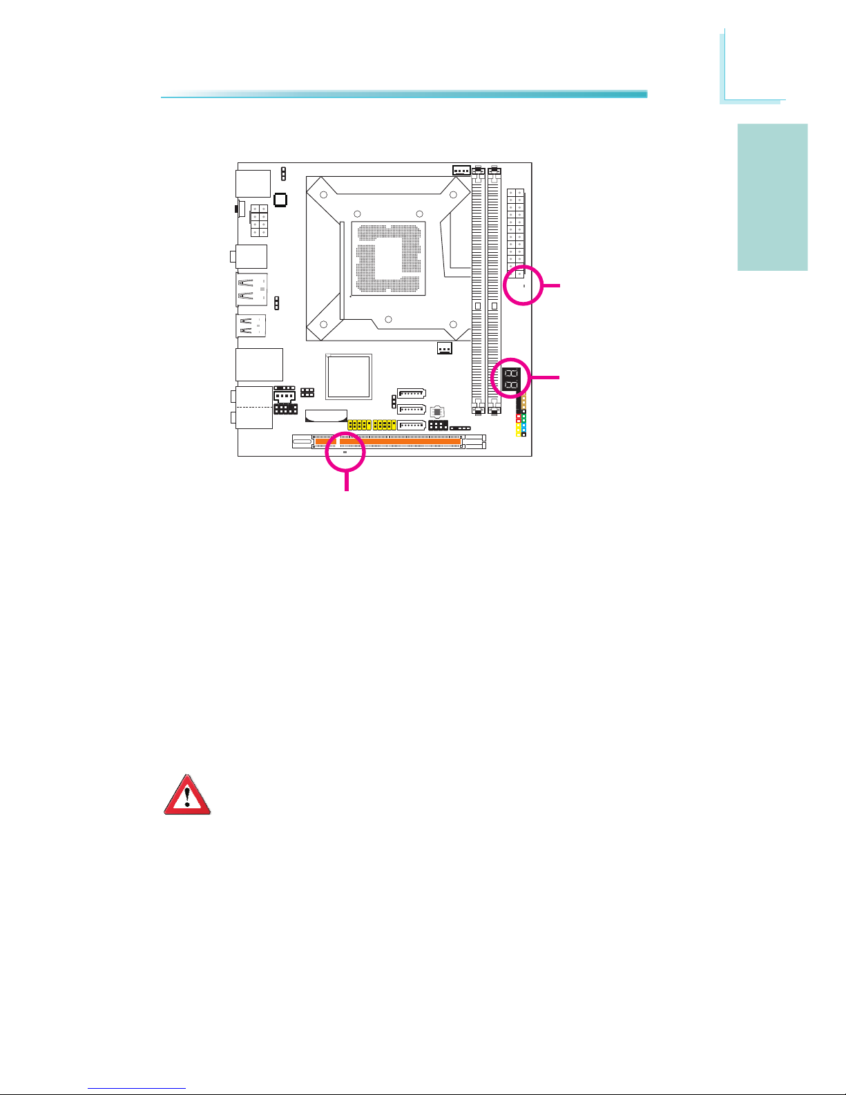
DRAM Power LED
Standby Power LED
LEDs
Diagnostic LED
DRAM Power LED
This LED will light when the system’s power is on.
Standby Power LED
This LED will light when the system is in the standby mode.
Diagnostic LED
The Diagnostic LED displays POST codes. POST (Power-On Self Tests) which is
controlled by the BIOS is performed whenever you power-on the system. POST
will detect the status of the system and its components. Each code displayed on
the LED corresponds to a certain system status.
Important:
When the DRAM Power LED and/or Standby Power LED lit red, it indicates that power is present on the DIMM sockets and/or PCI slots. Power-off the PC then unplug the power cord prior to installing any memory
modules or add-in cards. Failure to do so will cause severe damage to
the motherboard and components.
Page 22
22
English
E
English
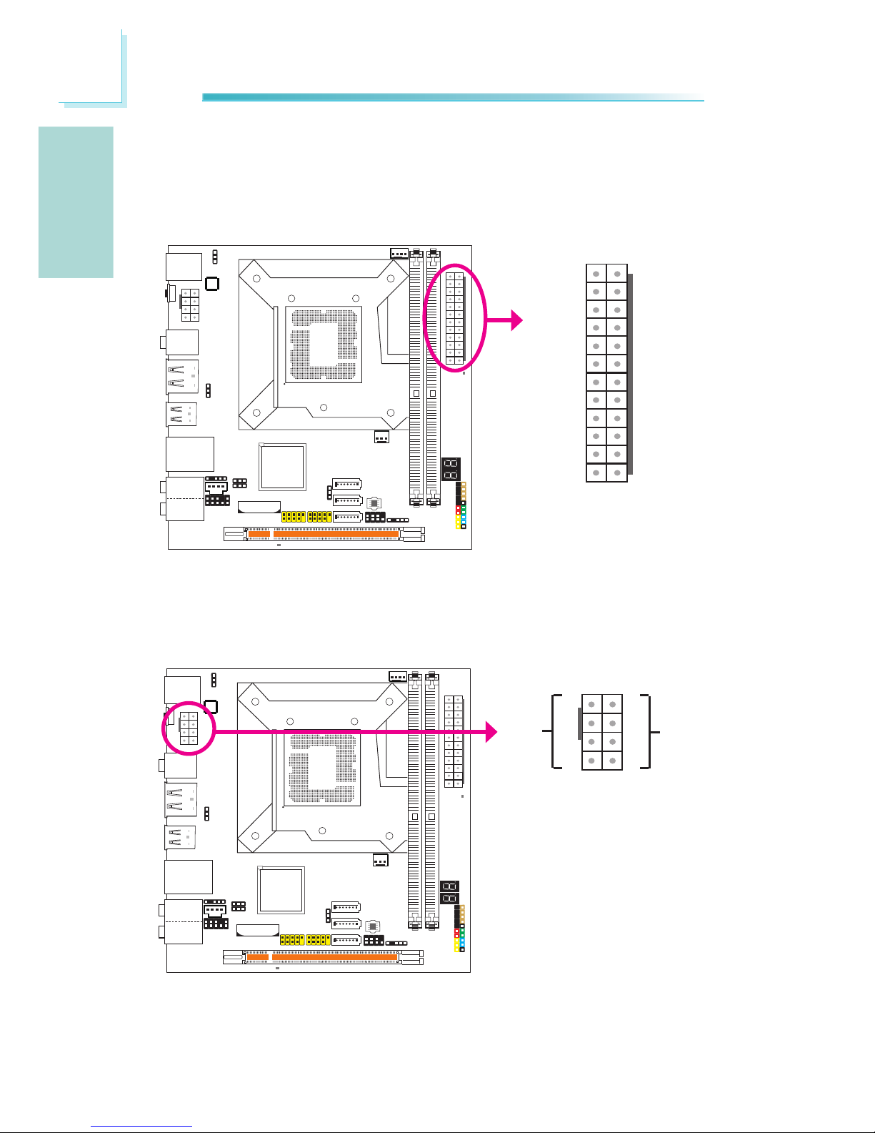
Power Connectors
Use a power supply that complies with the ATX12V Power Supply Design Guide
Version 1.1. An ATX12V power supply unit has a standard 24-pin ATX main power
connector that must be inserted into this connector.
Your power supply unit may come with an 8-pin or 4-pin +12V power connector.
The +12V power enables the delivery of more +12VDC current to the processor’s
Voltage Regulator Module (VRM). If available, it is preferable to use the 8-pin
power; otherwise connect a 4-pin power to this connector.
13
12 24
1
+3.3VDC
+3.3VDC
COM
+5VDC
COM
+5VDC
COM
PWR_OK
+5VSB
+12VDC
+12VDC
+3.3VDC
+3.3VDC
-12VDC
COM
PS_ON#
COM
COM
COM
NC
+5VDC
+5VDC
+5VDC
COM
+12V
Ground
1
4
5
8
Page 23
23
English
E
English
The system board requires a minimum of 200 Watt power supply to operate. Your
system conguration (CPU power, amount of memory, add-in cards, peripherals,
etc.) may exceed the minimum power requirement. To ensure that adequate
power is provided, we strongly recommend that you use a minimum of 300 Watt
(or greater) power supply.
Important:
Insufcient power supplied to the system may result in instability or
the add-in boards and peripherals not functioning properly. Calculating
the system’s approximate power usage is important to ensure that the
power supply meets the system’s consumption requirements.
The power connectors from the power supply unit are designed to t the 24-pin
and 8-pin connectors in only one orientation. Make sure to nd the proper orien-
tation before plugging the connectors.
Restarting the PC
Normally, you can power-off the PC by:
1. Pressing the power button at the front panel of the chassis.
or
2. Pressing the power switch that is on the system board (note: not all system
boards come with this switch).
If for some reasons you need to totally cut off the power supplied to the PC,
switch off the power supply or unplug the power cord. Take note though that if
you intend to restart it at once, please strictly follow the steps below.
1. The time where power is totally discharged varies among power supplies. It’s
discharge time is highly dependent on the system’s conguration such as the
wattage of the power supply, the sequence of the supplied power as well as
the number of peripheral devices connected to the system. Due to this reason, we strongly recommend that you wait for the Standby Power LED (refer
to the “LEDs” section in this chapter for the location of the Standby Power
LED) to lit off.
2. After the Standby Power LED has lit off, wait for 6 seconds before powering
on the PC.
If the system board is already enclosed in a chassis which apparently will not
make the Standby Power LED visible, wait for 15 seconds before you restore
power connections. 15 seconds is approximately the time that will take the
LED to lit off and the time needed before restoring power.
The above will ensure protection and prevent damage to the motherboard and
components.
Page 24
24
English
E
English
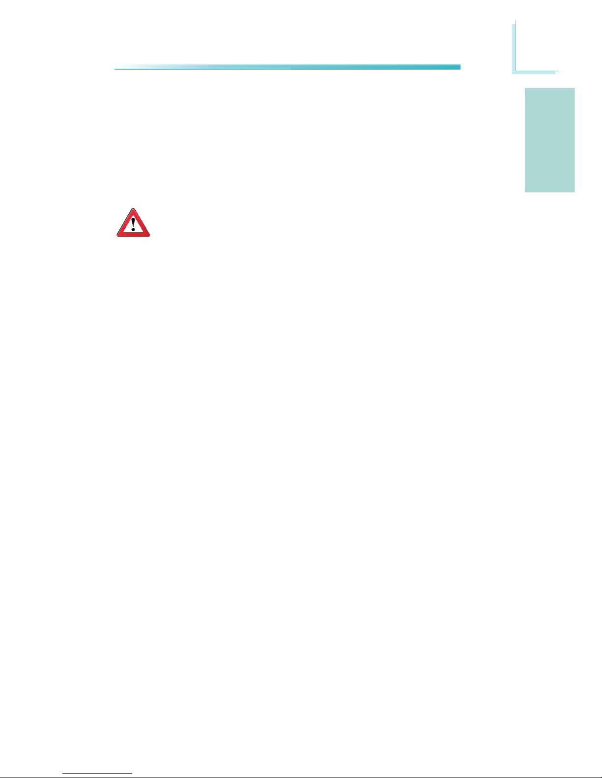
Front Panel Connectors
HD-LED: Primary/Secondary IDE LED
This LED will light when the hard drive is being accessed.
RESET: Reset Switch
This switch allows you to reboot without having to power off the system thus
prolonging the life of the power supply or system.
SPEAKER: Speaker Connector
This connects to the speaker installed in the system chassis.
ATX-SW: ATX Power Switch
Depending on the setting in the BIOS setup, this switch is a “dual function power
button” that will allow your system to enter the Soft-Off or Suspend mode.
1
2
1920
SPEAKER
HD-LED
RESET
PWR-LED
ATX-SW
Page 25
25
English
E
English
PWR-LED: Power/Standby LED
When the system’s power is on, this LED will light. When the system is in the
S1 (POS - Power On Suspend) or S3 (STR - Suspend To RAM) state, it will blink
every second.
Note:
If a system did not boot-up and the Power/Standby LED did not light after it was powered-on, it may indicate that the CPU or memory module
was not installed properly. Please make sure they are properly inserted
into their corresponding socket.
HD-LED
(Primary/Secondary IDE LED)
Reserved
ATX-SW
(ATX power switch)
Reserved
RESET
(Reset switch)
SPEAKER
(Speaker connector)
PWR-LED
(Power/Standby LED)
Pin Assignment
HDD LED Power
HDD
N. C.
N. C.
PWRBT+
PWRBT-
N. C.
N. C.
Ground
H/W Reset
Speaker Data
N. C.
Ground
Speaker Power
LED Power (+)
LED Power (+)
LED Power (-) or Standby Signal
Pin
3
5
14
16
8
10
18
20
7
9
13
15
17
19
2
4
6
Page 26
26
English
E
English
PCI Express Slot
PCIE 1
Download Flash BIOS Connector
1
2
8
7
GROUND
SPI_CLK
SPI_MOSI
SPI_VCC3
SPI_CS0B
SPI_MIS0
SPI_HOLD#
Page 27
27
English
E
English
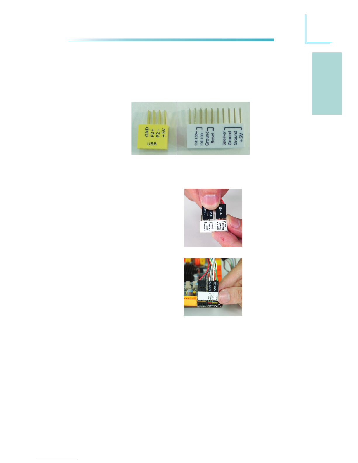
Smart Connectors
The Smart Connectors (USB, Front Panel) serve as extended connectors allowing
you to easily connect cables to the connectors that are on the system board. This
is specially advantageous when using the front panel connectors as this will prevent wrong cable connection.
1. Connect all front panel cables from
the chassis to the front panel smart
connector. Connect according to the
pin denition shown on the smart
connector.
Front Panel Connectors
USB Front Panel
2. Connect the front panel smart connector to the front panel connector
on the system board.
USB Connectors
1. Connect your USB port cable to the USB smart connector. Connect according
to the pin denition shown on the smart connector.
2. Connect the USB smart connector to the respective connectors on the system
board.
Page 28

28
English
E
English
The Intel chip allows conguring RAID on Serial ATA drives. It supports RAID 0,
RAID 1, RAID 0+1 and RAID 5.
RAID Levels
RAID 0 (Striped Disk Array without Fault Tolerance)
RAID 0 uses two new identical hard disk drives to read and write data in parallel,
interleaved stacks. Data is divided into stripes and each stripe is written alternately between two disk drives. This improves the I/O performance of the drives
at different channel; however it is not fault tolerant. A failed disk will result in
data loss in the disk array.
RAID 1 (Mirroring Disk Array with Fault Tolerance)
RAID 1 copies and maintains an identical image of the data from one drive to
the other drive. If a drive fails to function, the disk array management software
directs all applications to the other drive since it contains a complete copy of the
drive’s data. This enhances data protection and increases fault tolerance to the
entire system. Use two new drives or an existing drive and a new drive but the
size of the new drive must be the same or larger than the existing drive.
RAID 0+1 (Striping and Mirroring)
RAID 0+1 is a combination of data striping and data mirroring providing the ben-
ets of both RAID 0 and RAID 1. Use four new drives or an existing drive and
three new drives for this conguration.
RAID 5
RAID 5 stripes data and parity information across hard drives. It is fault tolerant
and provides better hard drive performance and more storage capacity.
Chapter 3 - RAID
Page 29
29
English
E
English
Settings
To enable the RAID function, the following settings are required.
1. Connect the Serial ATA drives.
2. Congure Serial ATA in the AMI BIOS.
3. Congure RAID in the RAID BIOS.
4. Install the RAID driver during OS installation.
5. Install the Intel Matrix Storage Manager.
Step 1: Connect the Serial ATA Drives
Refer to chapter 2 for details on connecting the Serial ATA drives.
Important:
1. Make sure you have installed the Serial ATA drives and connected the
data cables otherwise you won’t be able to enter the RAID BIOS utility.
2. Treat the cables with extreme caution especially while creating RAID.
A damaged cable will ruin the entire installation process and operating system. The system will not boot and you will lost all data in the
hard drives. Please give special attention to this warning because
there is no way of recovering back the data.
Step 2: Configure Serial ATA in the AMI BIOS
1. Power-on the system then press <Del> to enter the main menu of the AMI
BIOS.
2. Congure Serial ATA in the appropriate elds.
3. Select the Exit menu to exit the system setup.
4. Reboot the system.
Step 3: Configure RAID in the RAID BIOS
When the system powers-up and all drives have been detected, the Intel RAID
BIOS status message screen will appear. Press the <Ctrl> and <I> keys simultaneously to enter the utility. The utility allows you to build a RAID system on
Serial ATA drives.
Page 30

30
English
E
English
Step 4: Install the RAID Driver During OS Installation
The RAID driver must be installed during the Windows® XP or Windows® 2000 installation using the F6 installation method. This is required in order to install the
operating system onto a hard drive or RAID volume when in RAID mode or onto
a hard drive when in AHCI mode.
1. Start Windows Setup by booting from the installation CD.
2. Press <F6> when prompted in the status line with the ‘Press F6 if you need
to install a third party SCSI or RAID driver’ message.
3. Press <S> to “Specify Additional Device”.
4. At this point you will be prompted to insert a oppy disk containing the RAID
driver. Insert the RAID driver diskette.
5. Locate for the drive where you inserted the diskette then select RAID or AHCI
controller that corresponds to your BIOS setup. Press <Enter> to conrm.
You have successfully installed the driver. However you must continue installing
the OS. Leave the oppy disk in the oppy drive until the system reboots itself
because Windows setup will need to copy the les again from the oppy disk
to the Windows installation folders. After Windows setup has copied these les
again, remove the oppy diskette so that Windows setup can reboot as needed.
Step 5: Install the Intel Matrix Storage Manager
The Intel Matrix Storage Manager can be installed from within Windows. It allows
RAID volume management (create, delete, migrate) from within the operating
system. It will also display useful SATA device and RAID volume information. The
user interface, tray icon service and monitor service allow you to monitor the
current status of the RAID volume and/or SATA drives. It enables enhanced performance and power management for the storage subsystem.
Refer to the complete version of the manual for steps on installing Intel Matrix
Storage Manager. Please download the manual from DFI’s website. Visit www.d.
com.
Page 31

F
Français
31
Français
Processeur
Chipset
Mémoire Système
Logements
d’Extension
BIOS
Audio
LAN
Serial ATA
Panneau Arrière
I/O
Chapitre 1 - Spécifications
• LGA 1156 socket pour:
- Intel® Core i5/i7 Lynneld
• Prend en charge la technologie Turbo Boost d’Intel®
• Intel® P55 Express
• 2 sockets DIMM DDR3 240-pin
• Les modules DDR3 1600(O.C.)/1333/1066 MHz
• Jusqu’à 8GB de mémoire système
• Délivre jusqu’à 21 Go/s de largeur de bande à 1333 MHz
• L’interface de mémoire deux canaux (128-bit)
• Non-tamponns non-ECC DIMM
• 1 fentes x16 PCI Express (Gen 2)
• AMI BIOS
• BIOS 32Mo SPI ash
• CMOS Reloaded
• 8 chaînes Realtek ALC885 haute dénition audio CODEC
• DAC SNR/ADC SNR de 106dB/101dB
• Technologie protection de contente lossless à toute vitesse
• Interface optique S/PDIF et coaxial RCA S/PDIF
• Gigabit Ethernet PHY Intel 82578DC
• Entièrement conforme IEEE 802.3 (10BASE-T), 802.3u
(100BASE-TX) et 802.3ab (1000BASE-T) standard
• 3 dispositifs de SATA
- Technologie de Intel Matrix Storage
- SATA allant jusqu’à 3Gb/s
- RAID 0, RAID 1, RAID 0+1 et RAID 5
• 1 dispositifs de Power eSATA
• 1 port souris PS/2
• 1 port clavier PS/2
• 1 interrupteur effacement CMOS
• 1 port sortie optique S/PDIF
• 1 port sortie coaxial RCA S/PDIF
• 1 port Power eSATA
• 6 ports USB 2.0/1.1 (dont un partagé avec l’eSATA au-
toalimenté)
• 1 port RJ45 LAN
• Center/subwoofer, rear R/L et side R/L prises audio
• Line-in, line-out et mic-in prises audio
Page 32

Français
F
32
Français
Interne I/O
Gestion de
Puissance
Fonctions de
Moniteur de
Matériel
PCB
• 2 connecteurs pour 4 ports USB 2.0 supplémentaires
• 1 connecteur audio frontal
• 1 connecteur CD-in audio internes
• 1 connecteur S/PDIF
• 1 connecteur IrDA
• 3 connecteurs Serial ATA
• 1 connecteur d’alimentation ATX 24-pin
• 1 connecteur d’alimentation ATX 8-pin 12V
• 1 connecteur devant panneau
• 2 connecteurs de ventilateurs
• 1 connecteur de download ash BIOS
• 1 diagnostic LED
• ACPI et OS Directed Power Management
• ACPI STR (Suspend to RAM) fonction
• Réveil-Sur-PS/2 Clavier/Souris
• Réveil-Sur-USB Clavier
• Réveil Par Le Réseau
• Minuterie RTC pour allumer le système
• Récupération après Défaillance d’Alimentation CA
• Gère l’alarme de température et de surchauffe de CPU /
Chipset /PWM
• Gère l’alarme de voltage et d’échec de CPU/DRAM/VTT/
CPU_PLL/+3.3/+5/+12/+5VSB/Vbat
• Gère la vitesse de ventilateur du ventilateur
• Protection du CPU - supporte la mise hors circuit automa-
tique en cas de surchauffage du système
• 6 layers, facteur de forme de Mini-ITX
• 17cm (6.7”) x 17cm (6.7”)
Page 33

F
Français
33
Français
Chapitre 2 - Installation de Matériel
Cavalier
Si vous rencontrez les éléments suivants,
a) Données CMOS devenant corrompues
b) Vous avez oublié le superviseur ou le mot de passe utilisateur
c) Les réglages surcadencés dans le BIOS ont entraîné une instabilité du sys-
tème ou causés des problèmes de démarrage du système.
Vous devez recongurer le système aux valeurs par défaut stockées dans la ROM
BIOS.
Interrupteur effacement CMOS
L’interrupteur d’effacement du CMOS dans le panneau arrière du système vous
donne la facilité d’effacer le CMOS sans avoir à ouvrir le boîtier. Appuyez sur le
bouton noir pour effacer les données du CMOS.
JP2
Pour charger les valeurs par défaut dans la ROM BIOS, veuillez suivre les étapes
ci-dessous.
1. Débrancher le système et retirer le cordon d’alimentation.
2. Mettre les broches du JP2 2 et 3 sur ON Attendre quelques secondes et
remettre JP2 par défaut, broches 1 et 2 On.
3. Rebrancher maintenant le cordon d’alimentation et allumer le système.
Effacer les Données CMOS
2-3 On:
Clear CMOS Data
JP2
31 2
31
2
Clear CMOS
switch
1-2 On:
Effacer les données
CMOS
2-3 On:
Effacer les données
CMOS
Page 34

Français
F
34
Français
Sélectionner l’alimentation PS/2
En sélectionnant 5VSB, vous pourrez utiliser le clavier PS/2 ou la souris PS/2
pour “réveiller” le système.
Important:
La source d’alimentation 5VSB de votre alimentation doit supportée
≥720mA.
JP8
3
1
2
3
1
2
2-3 On:
5VSB
1-2 On: 5V
(défaut)
Page 35

F
Français
35
Français
Sélectionner l’alimentation USB
En sélectionnant 5VSB, vous pourrez utiliser le clavier USB pour “réveiller” le
système.
Important:
La source d’alimentation 5VSB de votre alimentation doit supportée
≥1,5(2 ports) ou ≥2 A(3 ou davantage de ports).
USB 8-13
(JP5)
3
1
2
3
1
2
2-3 On:
5VSB
1-2 On: 5V
(défaut)
1
3
2
1
3
2
2-3 On:
5VSB
1-2 On: 5V
(défaut)
USB 0-3
(JP6)
Page 36

Français
F
36
Français
Ports I/O de l’arrière du Panneau
Sortie Optique
S/PDIF
Sortie Coaxial
RCA S/PDIF
Souris PS/2
Clavier PS/2
Réinitialisation de l’horloge temps réel secondaire
Lorsque la pile de l’horloge est enlevée, ce cavalier réinitialise la capacité de gestion des octets du registre de l’horloge.
Note:
1. L’entrée SRTCRST# doit toujours être élevée lorsque toutes les autres couches Power plane de l’horloge sont ON.
2. Dans le cas où la pile de l’horloge soit inopérante ou manquante sur
la plateporme la broche SRTCRST# doit être montée avant la broche
RSMRST#.
Clear CMOS
switch
USB 8 USB 12-13
Mic-in
Side R/L
Center/Subwoofer
Rear R/L
Line-in
Front R/L
LAN
USB 9
eSATA Autoalimenté ou USB 11
USB 10
2-3 On:
RTC Reset
1-2 On: Normal
(défaut)
JP12
31 2
31 2
Page 37

F
Français
37
Français
Ports Souris PS/2 et Clavier PS/2
Ces ports sont utilisés pour raccorder une souris PS/2 et un clavier PS/2.
Prises Coaxiale de RCA S/PDIF et Optique de S/PDIF
Ces prises sont utilisées pour connecter les appareils de sortie audio externes en
utilisant les câbles coaxiaux et optique S/PDIF.
Important:
NE PAS utiliser un câble S/PDIF et RCA S/PDIF coaxial en même temps.
Connecteur S/PDIF
Le connecteur S/PDIF s’utilise pour brancher un port externe S/PDIF. Votre port
S/PDIF peut être monté sur un connecteur de bord de carte. Installez le connect-
eur de bord de carte dans une fente disponible à l’arrière du châssis du système,
puis branchez le câble audio au connecteur S/PDIF. Vériez que la broche 1 du
câble audio soit alignée avec la broche 1 du connecteur S/PDIF.
Ports PS/2 et S/PDIF
Souris PS/2
Clavier PS/2
Optique S/PDIF
Coaxiale de
RCA S/PDIF
S/PDIF
1 5
+5V
Key
SPDIF out
Ground
SPDIF in
Page 38

Français
F
38
Français
Port Power eSATA
La èche ci-dessus montre l’emplacement partagé par l’eSATA d’alimentation et
USB 11. Vous pouvez choisir de brancher, soit un périphérique d’alimentation
eSATA, soit un dispositif USB. Ce port fournit l’énergie sufsante pour actionner
un périphérique eSATA (pas besoin d’alimentation externe).
Port partagé par
l’Alimentation eSATA
et l’USB 11
Power eSATA
Page 39

F
Français
39
Français
Ports USB et LAN
Ports USB
Les ports USB sont utilisés pour raccorder des appareils USB 2.0/1.1. Les connecteurs 10 broches vous permettent de raccorder 4 autres ports USB 2.0/1.1.
Vos ports USB peuvent être livrés montés sur un support encartable. Installer le
support encartable dans une fente disponible à l’arrière du châssis du système et
raccorder les câbles des ports USB à ces connecteurs.
L’USB 11 est un port partagé avec l’eSATA autoalimenté. Si vous utilisez un
périphérique eSATA autoalimenté, vous pouvez utiliser ce port pour brancher un
périphérique USB.
Ports LAN
Les ports LAN permettent à la carte système de se connecter à un réseau local
au moyen d’un concentrateur réseau.
USB 0-1
USB 10
LAN
USB 11 /
Power eSATA
USB 12
USB 13
USB 2-3
1
VCC
-Data
+Data
GND
Key
VCC
-Data
+Data
GND
GND
2
10
9
USB 9
USB 8
Page 40

Français
F
40
Français
Audio et CD-In
Prise de caisson de basse/central (Center/Subwoofer) (orange)•
Cette prise est utilisée pour se connecter aux haut-parleurs de basse et cen-
traux du système audio.
Prise arrière gauche/droite (noire)•
Cette prise est utilisée pour se connecter aux haut-parleurs arrière droits et
gauches du système audio.
Prise de côté gauche/droite (grise)•
Cette prise est utilisée pour se connecter aux haut-parleurs de côté droits et
gauches du système audio.
Prise entrée (bleue claire)•
La prise est utilisée pour raccorder tous les appareils audio tels que Hi-, lec-
teur CD, lecteur de bande magnétique, radio AM/FM, synthéthiseur, etc..
Prise de sortie (Citron)•
Cette prise est utilisée pour se connecter aux haut-parleurs avant droits et
gauches du système audio.
Connecteur
audio frontal
Rear audio
Front R/L
Line-in
Mic-in
Rear R/L
Center/
Subwoofer
Side R/L
CD-in
1
Mic2-L
Line2-R
Front_IO_Sense
GND
Presence Signal
Key
2
10
Mic Jack Sense
Line-out Jack
Sense
9
Mic2-R
Line2-L
4
1
Left audio
channel
Right audio
channel
Ground
Ground
Page 41

F
Français
41
Français
Prise entrée micro (rose)•
Cette prise est utilisée pour connecter un microphone externe.
Connecteur Audio Frontal
Le connecteur audio frontal est utilisé pour raccorder les prises micro d’entrée et
les sorties de ligne (line-out) sur le panneau frontal de votre système.
Connecteur d’entrée CD
Le connecteur d’entrée CD est utilisé pour recevoir les signaux audio d’un lecteur
CD-ROM, d’une carte TV ou MPEG.
Les Connecteurs en Série ATA
Connecteurs I/O
Les connecteurs en série ATA (SATA) sont utilisés pour raccorder les disques durs
ATA en série. Relier une extrémité du câble en série ATA au connecteur en série
ATA et l’autre extrémité sur votre appareil en série ATA.
Configuration du Système RAID
Se référer au chapitre RAID de ce manuel pour obtenir davantage d‘informations
sur la création d’un système RAID sur les disques durs en série ATA.
7
RXN
GND
TXP
TXN
GND
1
RXP
GND
SATA 0
SATA 1
SATA 3
Page 42

Français
F
42
Français
Connecteur IrDA
Ce connecteur est utilisé pour raccorder un module IrDA.
Note:
La séquence de la fonction des broches (signal) sur certains câbles IrDA
peut être inversée à partir de la fonctionnalité dénie sur la carte système. S’assurer de relier le connecteur du câble sur le connecteur IrDA
selon les fonctions de leurs broches.
Il se peut que vous deviez installer les disques dans votre système d’exploitation
convenants à l’utilisation de la fonctionnalité IrDA Se référer au manuel de
votre système d’exploitation ou à la documentation pour obtenir davantage
d’informations.
1 5
VCC
N. C.
IRRX
Ground
IRTX
Page 43

F
Français
43
Français
Connecteurs de Ventilateur de Refroidissement
Ces connecteurs de ventilateur sont utilisés pour raccorder les ventilateurs de
refroidissement. Les ventilateurs de refroidissement fournissent une ventilation
adéquate à l’intérieur du châssis an d’empêcher toute surchauffe du processeur
et des composants de la carte système.
CPU fan
4
1
Sense
Power
Ground Speed
Control
3
1
Sense
Power
Ground
PWM fan
Page 44

Français
F
44
Français
LED
LED Alimentation DRAM
Ce voyant DEL s’allumera lorsque le système est allumé.
LED Alimentation Veille
Ce voyant DEL s’allumera lorsque le système est en mode veille.
LED de Diagnostic
Le voyant DEL de diagnostic afche les codes POST. POST (tests automatiques
d’alimentation) qui est contrôlé par le BIOS est effectué à chaque fois que le
système est allumé. ¨POST détectera le statut du système et de ses compos-
ants. Chaque code afché sur le voyant DEL correspond à un certains statut du
système.
Avertissement:
Lorsque le voyant DEL d’alimentation DRAM et/ou d’alimentation à l’état
de veille sont rouge, cela indique que le courant passe dans les supports
DIMM et/ou dans les fentes PCI. Eteindre le PC et débrancher le cordon d’alimentation avant d’installer les modules mémoire ou les cartes
d’extension. Un échec à effectuer ceci peut entraîner des dégâts graves
à la carte mère et ses composants.
LED alimentation
DRAM
LED alimentation veille
LED de
diagnostic
Page 45

F
Français
45
Français
Connecteurs d’alimentation
Utiliser une alimentation électrique conforme à la version 1.1 du guide
d’alimentation électrique ATX12V. Une unité d’alimentation électrique ATX12V
possède un connecteur d’alimentation principale ATX à 24 broches qui doit être
inséré dans ce connecteur.
Votre unité d’alimentation électrique peut être livrée avec un connecteur
d’alimentation 12V à 4 ou 8 broches. L’alimentation 12V permet la fourniture de
courant 12VDC en direction du module de régulation de tension du processeur
(VRM - Voltage Regulator Module). Si disponible, il est préférable d’utiliser une
alimentation 8 broches, sinon, raccorder une alimentation 4 broches à ce connecteur.
13
12 24
1
+3.3VDC
+3.3VDC
COM
+5VDC
COM
+5VDC
COM
PWR_OK
+5VSB
+12VDC
+12VDC
+3.3VDC
+3.3VDC
-12VDC
COM
PS_ON#
COM
COM
COM
NC
+5VDC
+5VDC
+5VDC
COM
+12V
Ground
1
4
5
8
Page 46

Français
F
46
Français
La carte système nécessite une alimentation minimale de 200 Watts pour pou-
voir fonctionner. La conguration de votre système (alimentation du processeur,
cartes d’extension, périphériques etc.) peut dépasser la puissance minimale req-
uise. Pour s’assurer que la puissance minimale soit fournie, nous vous conseillons
fortement d’utiliser une alimentation minimale de 300 Watts (ou davantage).
Important:
Une puissance insufsante fournie au système peut entraîner une instabilité ou un mauvais fonctionnement des cartes d’extension et des
périphériques. Le calcul de la puissance approximative requise par le
système est important pour garantir que l’alimentation soit sufsante
pour la consommation du système.
Les connecteurs d’alimentation de l’unité d’alimentation électrique sont conçus
pour s’adapter aux connecteurs à 24 et 8 broches seulement dans une direction.
S’assurer d’observer la bonne orientation avant de brancher les connecteurs.
Redémarrage du PC
Normalement vous pouvez éteindre le PC en :
1. Appuyant sur le bouton d’alimentation sur le panneau frontal du chassis.
ou
2. En appuyant sur le commutateur d’alimentation se trouvant sur la carte système (note : toutes les cartes systèmes ne possèdent pas ce commutateur)
Si, pour quelque raison que ce soit, vous devez éteindre l’alimentation du PC,
éteindre l’alimentation ou débrancher le cordon d’alimentation. Veuillez noter que
si vous désirez le redémarrer de suite, suivez les étapes suivantes :
1. Le temps de déchargement de l’électricité dépend des alimentations élec-
triques. Le temps de déchargement dépend entièrement de la conguration
du système telle que le nombre de Watt de l’alimentation, de la séquence de
l’alimentation ainsi que du nombre d’appareils périphériques reliés au système. Pour ces raisons nous conseillons fortement d’attendre que le voyant
DEL de veille (se référer à la section « voyants DEL » de ce chapitre pour la
localisation de ce voyant) s’éteigne.
2. Une fois le voyant DEL de veille éteint, attendre 6 secondes avant d’allumer
le PC.
Si la carte système est déjà montée dans un châssis qui apparemment ne
laissera pas entrevoir le voyant DEL de veille, attendre 15 secondes avant de
restaurer les connexions électriques. 15 secondes est environ le temps que
prendra le voyant DEL pour s’éteindre et le temps nécessaire avant la restauration de l’alimentation.
Ceci garantit une protection et empêche les dégâts graves éventuels à la carte
mère et à ses composants.
Page 47

F
Français
47
Français
Connecteurs Frontaux du Panneau
HD-LED: Voyant DEL IDE Principal/Secondaire
Ce voyant DEL s’allumera lorsqu’on accède au disque dur.
RESET: Commutateur de Réinitialisation
Ce commutateur vous permet de redémarrer sans avoir à éteindre le système et
par conséquent en permettant une durée de vie de l’alimentation ou du système
prolongée.
SPEAKER: Connecteur du Haut-parleur
Il se connecte au haut parleur installé dans le châssis du système.
ATX-SW: Commutateur d’alimentation ATX
Dépendant des réglages à l’intérieur du BIOS, ce commutateur est un « bouton
d’alimentation à deux fonctions » qui permettra à votre système d’entrer en
mode Soft-Off ou Suspend.
PWR-LED: Voyant DEL d’alimentation / état de veille
Ce voyant DEL s’allumera lorsque le système est allumé. Lorsque le système est
sur le statut S1 (POS – alimentation suspendue) ou S3 (STR – suspendue dans la
RAM), il clignotera toutes les secondes.
Note:
Si le système n’a pas démarré et que le voyant DEL d’alimentation/veille
ne s’est pas allumé après le démarrage, cela peut indiquer que le processeur ou le module n’ont pas été installés correctement. Veuillez vous
assurer qu’ils soient correctement insérés dans leur support.
1
2
1920
SPEAKER
HD-LED
RESET
PWR-LED
ATX-SW
Page 48

Français
F
48
Français
HD-LED
LED d’IDE primaire/secondaire
Reserved
ATX-SW
Inte rrup teur d’a lluma ge de
l’alimentation ATX
Reserved
RESET
Interrupteur Reset
SPEAKER
Prise haut-parleur
PWR-LED
LED Marche/Veille
Affectation des Broches
HDD LED Power
HDD
N. C.
N. C.
PWRBT+
PWRBT-
N. C.
N. C.
Ground
H/W Reset
Speaker Data
N. C.
Ground
Speaker Power
LED Power (+)
LED Power (+)
LED Power (-) or Standby Signal
Broches
3
5
14
16
8
10
18
20
7
9
13
15
17
19
2
4
6
Page 49

F
Français
49
Français
Fentes PCI Express
PCIE 1
Connecteur de Download Flash BIOS
1
2
8
7
GROUND
SPI_CLK
SPI_MOSI
SPI_VCC3
SPI_CS0B
SPI_MIS0
SPI_HOLD#
Page 50

Français
F
50
Français
Connecteurs Smart
Les connecteurs Smart (USB, panneau avant) servent de rallonge de connecteurs
vous permettant de facilement raccorder des câbles aux connecteurs se trouvant
sur la carte mère. Ceci est particulièrement utile aux connecteurs du panneau
avant car cela empêchera le raccordement de câbles ne convenant pas.
1. Raccordez tous les câbles du panneau avant du châssis au connecteur Smart du panneau avant.
Raccordez en fonction de la dénition de la broche indiquée sur le
connecteur Smart.
Connecteurs du Panneau Avant
USB
Connecteurs du Panneau
Avant
2. Raccordez le connecteur Smart du
panneau avant au connecteur du
panneau avant de la carte système.
Connecteurs USB
1. Raccordez votre câble du port USB au connecteur Smart USB. Raccordez en
fonction de la dénition de la broche indiquée sur le connecteur Smart.
2. Raccordez le connecteur Smart USB aux connecteurs correspondants sur la
carte système.
Page 51

F
Français
51
Français
La puce Intel permet la conguration RAID sur les lecteurs Série ATA connectés.
Elle supporte les systèmes RAID 0, RAID 1, RAID 0+1 et RAID 5.
Niveaux du Système RAID
RAID 0 (matrice de disque à “0” erreur de tolérance)
RAID 0 utilise deux nouveaux disques durs identiques pour lire et graver en blocs
parallèles. Les données sont divisées en bandes et chaque bande est gravée al-
ternativement d’un disque à l’autre. Ceci améliore la performance I/O des disques
sur les différents canaux, cependant aucune tolérance d’erreur n’est admise. Un
disque défaillant résultera en une perte des données dans la matrice.
RAID 1 (matrice de disque à écriture mirroir à tolérance d’erreur)
RAID 1 copie et conserve une image identique des données d’un disque à l’autre.
Si un disque fonctionne incorrectement, le logiciel de gestion de la matrice envoie toutes les applications en direction de l’autre disque puisqu’il contient une
copie complète des données du disque. Ceci améliore la protection des données
et accroît la tolérance des erreurs dans tout le système. Utiliser deux nouveaux
disques durs ou un disque existant et un nouveau disque dur mais la taille du
nouveau disque dur doit être identique ou supérieure à celle de celui existant.
RAID 0+1 (bande et mirroir)
RAID 0+1 est une combinaison de données mirroir et de bandes de données ap-
portant les avantages des systèmes RAID 0 et RAID 1. Utiliser quatre nouveaux
disques durs ou un disque existant et trois nouveaux disques pour cette congu-
ration.
RAID 5
RAID 5 répartit en écriture les données et les informations concernant la parité
sur les disques durs. Il est insensible aux défaillances et permet d’obtenir de bien
meilleures performances des disques durs ainsi qu’une capacité de stockage accrue.
Chapitre 3 - RAID
Page 52

Français
F
52
Français
Réglages
Pour activer la fonctionnalité RAID, les réglages suivants sont nécessaires:
1. Raccorder les disques durs en série ATA.
2. Congurer le disque ATA en série dans le AMI BIOS.
3. Congurer les systèmes RAID dans le BIOS RAID.
4. Installer le driver RAID lors de l’installation du SE (système d’expl
ion.
).
5. Installer le Intel Matrix Storage Manager.
Etape 1 : Raccorder les disques durs en série ATA.
Se référer au chapitre 2 pour obtenir davantage de détails sur la connexion des
disques durs en série ATA.
Important:
1. S’assurer d’avoir installé les disques en série ATA et d’avoir raccordé
les câbles de données sinon vous ne pourrez entrer dans l’utilitaire
BIOS RAID.
2. Faire très attention aux câbles et particulièrement en créant le
système RAID. Un câble endommagé détériorera tout le processus
d’installation et le SE. Le système ne démarrera pas et vous perdrez
toutes les données des disques durs. Veuillez prêter attention à cet
avertissement car il n’existe aucun moyen de récupérer les informa-
tions.
Etape 2 : Configurer le disque ATA en série dans le AMI BIOS
1. Mettez le système en marche, puis appuyez sur <Del> pour entrer au menu
principal du BIOS AMI.
2. Congurer l’ATA série dans les champs adéquats.
3. Sélectionnez le menu “Exit” pour quitter le paramétrage du système.
4. Redémarrez le système.
Etape 3 : Configurer le système RAID dans le BIOS RAID
Congurer le système RAID dans le BIOS RAID Intel. Lorsque le système démarre et que tous les disques durs ont été détectés, le message de statut du
BIOS Intel apparaîtra. Appuyer sur la touche <Ctrl>+<I> pour entrer dans
l’utilitaire. L’utilitaire vous permet de créer un système RAID sur des disques durs
en série ATA.
Page 53

F
Français
53
Français
Etape 4 : Installer le driver RAID lors de l’installation du SE (système
d’explion.).
Le driver RAID doit être installé lors de l’installation de Windows® XP ou de
Windows® 2000 en utilisant la méthode d’installation F6. Ceci est nécessaire an
d’installer le SE sur un disque dur ou sur un volume RAID lors du mode RAID ou
sur un disque dur lors du mode AHCI.
1. Lancer l’installation de Windows en démarrant depuis le CD d’installation.
2. Appuyer sur <F6> lors de la demande dans la ligne de statut en utilisant la
touche F6 si vous avez besoin d’installer une troisième partie SCSI ou lors
d’un message du driver RAID.
3. Appuyer sur <S> pour « spécier un appareil supplémentaire ».
4. A ce moment on vous demandera d’insérer une disquette contenant le driver
RAID. Insérer la disquette contenant le driver RAID.
5. Localiser le lecteur dans lequel vous avez inséré la disquette et sélectionner
le système RAID ou le contrôleur AHCI correspondant à votre installation du
BIOS. Appuyer sur <Enter> pour conrmer.
Vous avez réussi à installer le driver. Cependant vous devez continuer à installer
le SE. Laisser la disquette dans le lecteur de disquette jusqu’à ce que le système rédémarre tout seul car lors de l’installation de Windows les chiers seront
copiés depuis la disquette sur les dossiers d’installation de Windows. Une fois les
chiers copiés lors de l’installation de Windows, retirer la disquette an de laisser
l’ordinateur redémarrer après l’installation de Windows.
Etape 5: Installer le Intel Matrix Storage Manager
Se référer à la version complète du manuel pour les étapes d’installation du
progiciel et du pilote. Veuillez télécharger le manuel depuis le site Web de DFI:
www.DFI.com.
Page 54

Deutsch
G
54
Deutsch
Kapitel 1 - Spezifikation
Prozessor
Chipset
Systemspeicher
Expansion Schlitz
BIOS
Audio
LAN
Serial ATA
Porte an der
Rückwand
• LGA 1156 CPU Einfaßung für:
- Intel® Core i5/i7 Lynneld Prozessoren
• Unterstützt Intel® Turbo Boost Technologie
• Intel® P55 Express chipset
• 2 240-pin-Steckplätze DDR3 DIMM
• Moduln DDR3 1600(O.C.)/1333/1066 MHz
• Bis zum 8GB-Systemspeicher
• Bietet bis zu 21Gb/s Bandbreite bei 1333MHz
• 128-bit – Speiher mit den zwei Kanälen
• DIMMs ohne Dämpfer non-ECC
• 1 PCI Express (Gen 2) x16-Einbauplätzen
• AMI BIOS
• 32Mbit SPI Flash BIOS
• CMOS Reloaded
• Realtek ALC885 8-Kanal-Hohe-Denition-audio-CODEC
• DAC SNR/ADC SNR von 106dB/101dB
• Lossless zufriedene Schutzvollwegtechnologie
• S/PDIF-Aus optischen und S/PDIF-Aus coaxial RCA
Schnittstelle
• Intel 82578DC Gigabit Ethernet PHY
• Völlig gefällig zu IEEE 802.3 (10BASE-T), 802.3u
(100BASE-TX) und 802.3ab (1000BASE-T) standards
• 3 SATA-Vorrichtungen
- Intel Matrix Storage technologie
- SATA bis zu 3Gb/s schnell
- RAID 0, RAID 1, RAID 0+1 und RAID 5
• 1 Power eSATA-Vorrichtungen
• 1 Mini-DIN-6-Anschluß für eine PS/2-Maus
• 1 Mini-DIN-6-Anschluß für eine PS/2-Tastatur
• 1 Clear CMOS Schalter
• 1 S/PDIF optischen-Anschlüsse
• 1 S/PDIF coaxial RCA-Anschlüsse
• 1 Power eSATA-Anschlüsse
• 6 USB 2.0/1.1-Anschlüsse (einer shared mit Power eSATA)
• 1 RJ45 LAN-Anschlüsse
• Center/subwoofer, rear R/L und side R/LAudio-Anschlußbu-
chsen
• Line-in, line-out und mic-in Audio-Anschlußbuchsen
Page 55

G
Deutsch
55
Deutsch
Internes I/O
Energie
Management
Kleinteilmonitor
PCB
• 2 Anschlußfassung für 4 zusätzliche externe USB 2.0-
Anschlüsse
• 1 Front-Audioanschluss
• 1 CD-in-Anschluß
• 1 S/PDIF-Anschluß
• 1 IrDA-Anschluß
• 3 Serial-ATA-Anschlüsse
• 1 Anschlußstecker für das ATX-Netzgerät 24-pin
• 1 Anschlußstecker für das ATX-Netzgerät 8-pin 12V
• 1 Vorderseite Füllung Anschlüsse
• 2-ventilator-Anschlüsse
• 1-download-ash-BIOS-Anschlüsse
• 1 diagnostischen Außenindikatoren
• ACPI und OS Directed Power Management
• ACPI STR (Suspend to RAM) funktion
• Wecken bei Betätigung der PS/2 Tastatur/Maus
• Wecken bei USB-Tastatur
• Wecken des Systems durch das Netzwerk
• RTC-Taktgeber zum Einschalten des Systems
• Wiederherstellung der Wechselstromversorgung nach
einem Ausfall
• Überwachung der Temperatur des CPU/chipset/PWM sowie
Warnsignal bei Überhitzung
• Überwachung der Spannungen des CPU/DRAM/VTT/CPU_
PLL/+3.3/+5/+12/+5VSB/Vbat
• Überwachung der Geschwindigkeit des Ventilators
• Prozessor-Shutz - Die Ausschaltung bei der Überhitzung
– die automatische Ausschaltung des Computers bei der
Überhitzung
• 6 layers, Mini-ITX form factor
• 17cm (6.7”) x 17cm (6.7”)
Page 56

Deutsch
G
56
Deutsch
Kapitel 2 - Installieren des Hardware
Jumper
Sollten Sie eins der folgenden Probleme haben,
a) die CMOS Daten sind beschädigt.
b) Sie haben das Supervisor oder User Passwort vergessen.
c) die Übertaktungseinstellungen im BIOS haben zur Instabilität des Systems
geführt or System bereitet Probleme beim Booten.
so können Sie das System mit den im ROM BIOS gespeicherten Standardwerten
rekongurieren.
Clear CMOS Schalter
Der Clear CMOS Schalter an der Rückseite des Systems ermöglicht ein bequemes
Löschen des CMOS, ohne Entfernen der Chassisabdeckung. Drücken Sie zum
Löschen der CMOS-Daten die schwarze Taste.
JP2
Um die im ROM BIOS gespeicherten Standardwerte zu laden führen Sie bitte die
folgenden Schritte aus.
1. Schalten Sie das System aus und ziehen Sie den Netzstecker.
2. Setzen Sie die JP2 Pins 2 und 3 auf On. Warten Sie nun einige Sekunden und
setzen Sie dann die JP2 Pins zurück in die Ausgangsposition, Pins 1 und 2
On.
3. Verbinden Sie nun wieder den Netzstecker und schalten Sie das System ein.
Löschen der CMOS Daten
1-2 On: Normal
(Standardwert)
2-3 On:
Lösche CMOS Daten
JP2
31 2
31
2
Clear CMOS
switch
Page 57

G
Deutsch
57
Deutsch
Die Auswahl von 5VSB erlaubt es Ihnen, Ihr System per PS/2 Keyboard oder
PS/2 Maus aufzuwecken.
Wichtig:
Die 5VSB Stromquelle Ihres Netzteils muss ≥720mA unterstützen.
JP8
3
1
2
3
1
2
2-3 On:
5VSB
1-2 On: 5V
(Standardwert)
PS/2 Power Wählen Sie
Page 58

Deutsch
G
58
Deutsch
Die Auswahl von 5VSB erlaubt es Ihnen, Ihr System per USB Keyboard aufzuwecken.
Wichtig:
Die 5VSB Stromquelle Ihres Netzteils muss ≥1.5V (2 ports) oder ≥2V (3
oder mehr Ports) Vunterstützen.
USB Power Wählen Sie
USB 8-13
(JP5)
3
1
2
3
1
2
2-3 On:
5VSB
1-2 On: 5V
(Standardwert)
1
3
2
1
3
2
2-3 On:
5VSB
1-2 On: 5V
(Standardwert)
USB 0-3
(JP6)
Page 59

G
Deutsch
59
Deutsch
Porte an der Rückwand
Wird die RTC-Batterie entfernt, setzt diese Steckbrücke die Handhabbarkeit der
Registerbits der RTC zurück.
Hinweis:
1. Der SRTCRST# Input muss immer hoch sein, wenn alle anderen RTC
Versorgungslagen laufen.
2. In dem Fall dass die RTC-Batterie leer ist oder ganz fehlt, muss der
SRTCRST# Pin vor dem RSMRST# Pin stehen.
S/PDIF Optischen-
Anschlüsse
S/PDIF Coaxial RCA-
Anschlüsse
Clear CMOS
switch
USB 8 USB 12-13
Mic-in
Side R/L
Center/Subwoofer
Rear R/L
Line-in
Front R/L
LAN
USB 9
Versorgung über
eSATA oder USB 11
USB 10
Sekundären RTC-Reset
2-3 On:
RTC Reset
1-2 On: Normal
(Standardwert)
JP12
31 2
31 2
PS/2-Tastatur
PS/2-Maus
Page 60

Deutsch
G
60
Deutsch
PS/2 Maus und PS/2 Keyboard
Diese Ports werden zum Anschluss von PS/2 Maus und PS/2 Keyboard verwendet.
Coaxial RCA S/PDIF und Optischer S/PDIF Stecker
Mit diesen Steckern verbinden Sie externe Audioausgabegeräte die koaxiale/Optischer S/PDIF Kabel verwenden.
S/PDIF
Der S/PDIF Anschluss dient dem Anschluss eines externen S/PDIF Ports. Ihr S/
PDIF Port kann an einen Card-Edge Halter montiert werden. Installieren Sie den
Card-Edge Halter an einen verfügbaren Slot an der Rückseite des Systemchas-
sis und verbinden Sie anschließend das Audiokabel mit dem S/PDIF Anschluss.
Vergewissern Sie sich, dass Pin 1 des Audiokabel und Pin-1 des S/PDIF Anschluss
aufeinander abgestimmt sind.
Wichtig:
Verwenden Sie NICHT optische S/PDIF und koaxiale RCA S/PDIF gleichzeitig.
PS/2-Maus / PS/2-Tastatur-Anschlüsse und S/PDIF-Anschlüsse
PS/2-Maus
PS/2-Tastatur
S/PDIF Optisch-
en-Anschlüsse
S/PDIF Coaxial
RCA-Anschlüsse
S/PDIF
1 5
+5V
Key
SPDIF out
Ground
SPDIF in
Page 61

G
Deutsch
61
Deutsch
Power eSATA-Anschlüsse
Die obige Pfeil zeigt auf den von Power eSATA und USB 11 gemeinsam genutzten
Ort. Schließen Sie ein Power eSATA-Gerät oder ein USB-Gerät an. Die von diesem
Port gelieferte Stromversorgung reicht zur Nutzung eines eSATA-Gerätes aus
(keine zusätzliche Versorgung notwendig).
Versorgung shared
zwischen Power eSATA
und USB 11
Power eSATA
Page 62

Deutsch
G
62
Deutsch
USB
Über die USB Ports verbinden Sie USB 2.0/1.1 Geräte. Die 10-Pin Anschlüsse
erlauben Ihnen den Anschluss von 4 zusätzlichen USB 2.0/1.1 Ports. Ihre USB
Ports könnten auf einem Halterungsblech befestigt sein. Installieren Sie das Blech
in eine verfügbare Halterung an der Rückseite des Gehäuses und verbinden Sie
das Kabel des USB Ports mit dem entsprechenden Anschluss.
USB 11 ist ein Port, der auch von Power eSATA genutzt wird. Falls Sie ein Power
eSATA Gerät nutzen, können Sie diesen Port zum Anschluss eines USB Geräts
nutzen.
LAN
Über die LAN Ports können Sie das Systemboard über einen Netzwerk-Hub mit
einem lokalen Netzwerk verbinden.
USB und LAN-Anschlüsse
USB 0-1
USB 10
LAN
USB 11 /
Power eSATA
USB 12
USB 13
USB 2-3
1
VCC
-Data
+Data
GND
Key
VCC
-Data
+Data
GND
GND
2
10
9
USB 9
USB 8
Page 63

G
Deutsch
63
Deutsch
Audio und CD-In-Anschlüsse
Center/Subwoofer Stecker (Orange)•
Mit diesem Stecker verbinden Sie die Center und Subwoofer Lautsprecher
Ihres Audiosystems mit dem System.
Rear Right/Left Jack (Schwarz)•
Mit diesem Stecker verbinden Sie die hinten links und hinten rechts Lautsprecher Ihres Audiosystems mit dem System.
Side Right/Left Jack (Grau)•
Mit diesem Stecker verbinden Sie die seitlich links und seitlich rechts
Lautsprecher des Audiosystems mit dem System.
Line-in Stecker (Hellblau)•
Mit diesem Stecker verbinden Sie beliebige Audiogeräte wie z.B. Stereoanlagen, CD-Player, Kassettenrecorder, AM/FM Radios, Synthesizer, etc.mit dem
System.
Front R/L
Line-in
Mic-in
Rear R/L
Center/
Subwoofer
Side R/L
CD-in
1
Mic2-L
Line2-R
Front_IO_Sense
GND
Presence Signal
Key
2
10
Mic Jack Sense
Line-out Jack
Sense
9
Mic2-R
Line2-L
4
1
Left audio
channel
Right audio
channel
Ground
Ground
Fronttafelaudio
Anschlüsse
Rückseitiges Audio
Page 64

Deutsch
G
64
Deutsch
Serial ATA-Anschlüsse
I/O Anschlüsse
Line-out Stecker (Hellgrün)•
Mit diesem Stecker verbinden Sie die vorne links und vorne rechts Lautsprecher Ihres Audiosystems mit dem System.
Mic-in Stecker (Pink)•
Mit diesem Stecker verbinden Sie ein externes Mikrophon mit dem System.
Front Audio Anschluss
Mit dem Front Audio Anschluss werden die line-out und mic-in Stecker die sich an
der Frontseite des Gehäuses benden verbunden.
CD-in Anschluss
Der CD-in Anschluss wird verwendet, um Audio von einem CD-ROM Laufwerk,
einer TV Tuner oder MPEG-Karte zu empfangen.
Über die Serial ATA (SATA) Anschlüsse werden Serial ATA Laufwerke angeschlossen. Verbinden Sie das eine Ende des Serial ATA Kabels mit dem Serial ATA Anschluss und das andere Ende mit Ihrem Serial ATA Gerät.
RAID-Konfiguration
Bitte lessen Sie im Kapitel RAID dieses Handbuchs, um weitere Informationen zur
Erzeugung von RAID auf Serial ATA Laufwerken zu erhalten.
7
RXN
GND
TXP
TXN
GND
1
RXP
GND
SATA 0
SATA 1
SATA 3
Page 65

G
Deutsch
65
Deutsch
IrDA-Anschlüsse
Dieser Anschluss unterstützt ein Infrarotmodul.
Bitte beachten:
Die Anordnung der PIN-Funktionen kann bei einigen IrDA Kabeln abweichend von der Anordnung auf dem Systemboard sein. Bitte stellen Sie
sicher, dass die Pinbelegungen des Kabels und des IrDA Anschlusses auf
dem Systemboard miteinander übereinstimmen.
Um die IrDA Funktion nutzen zu können könnte es notwendig sein, die entsprechenden Treiber in Ihrem Betriebssystem zu installieren. Informationen hierzu
erhalten Sie aus dem Benutzerhandbuch des Betriebssystems.
1 5
VCC
N. C.
IRRX
Ground
IRTX
Page 66

Deutsch
G
66
Deutsch
Lüfteranschlüsse
Über diese Lüfteranschlüsse werden Lüfter mit dem System verbunden. Diese
Lüfter sorgen für ausreichende Luftzirkulation im Gehäuse und verhindern somit
ein Überhitzen der CPU und der Komponenten auf dem Systemboard.
CPU fan
4
1
Sense
Power
Ground Speed
Control
3
1
Sense
Power
Ground
PWM fan
Page 67

G
Deutsch
67
Deutsch
LEDs
DRAM Power-LED
Diese LED leuchtet wenn das System eingeschaltet ist.
Standby Power-LED
Diese LED leuchtet wenn das System im Standby Modus ist.
Diagnose-LED
Die Diagnose-LED zeigt POST Codes an. POST (Power-On Self Tests), die durch
das BIOS gesteuert werden, werden bei jedem Start des Systems durchgeführt.
Der POST erkennt den Status des Systems und seiner Komponenten. Jeder durch
die LED angezeigte Code entspricht einem bestimmten Systemstatus.
Warnung:
Eine aueuchtende DRAM Power LED und/oder Standby Power LED zeigt
an, dass die DIMM-Sockel und/oder PCI-Steckplätze unter Spannung ste-
hen. Schalten Sie den PC aus und ziehen Sie den Netzstecker bevor Sie
Speichermodule oder Zusatzkarten installieren. Bei Nichtbeachtung dro-
hen erhebliche Schäden am Motherboard und den Komponenten.
DRAM Power-LED
Standby Power-LED
Diagnose-LED
Page 68

Deutsch
G
68
Deutsch
Stromanschlüsse
Verwenden Sie ein Netzteil, dass den ATX12V Netzteil Designrichtlinien Version 1.1 entspricht. Ein ATX12V Netzteil verfügt über einen standard 24-Pin ATX
Hauptstromanschluss. Verbinden Sie diese Stromanschlüsse.
Ihr Netzteil könnte über einen 8-Pin oder 4-Pin +12V Anschluss verfügen. Der
+12V Anschluss erlaubt die Bereitstellung von mehr +12VDC Spannung für das
Voltage Regulator Module (VRM) des Prozessors. Falls verfügbar sollten Sie bevorzugt den 8-Pin Anschluss verwenden, falls nicht vorhanden den 4-Pin Anschluss.
13
12 24
1
+3.3VDC
+3.3VDC
COM
+5VDC
COM
+5VDC
COM
PWR_OK
+5VSB
+12VDC
+12VDC
+3.3VDC
+3.3VDC
-12VDC
COM
PS_ON#
COM
COM
COM
NC
+5VDC
+5VDC
+5VDC
COM
+12V
Ground
1
4
5
8
Page 69

G
Deutsch
69
Deutsch
Das Systemboard benötigt zum Betrieb ein Netzteil mit mindestens 200 Watt.
Ihre Systemkonguration (CPU Power, Grösse des Speichers, Zusatzkarten, Perpheriegeräte, etc.) können den Strombedarf des Systems zusätzlich erhöhen. Um
sicher zu stellen, dass ausreichende Stromversorgung zur Verfügung steht empfehlen wir, ein Netzteil mit mindestens 300 Watt oder mehr zu verwenden.
Wichtig:
Ungenügende Stromversorgung kann zu Instabilität führen oder fehlerhafte Funktion von Zusatzkarten und Peripheriegeräten zur Folge haben.
Die Berechnung des Stromverbrauchs des Systems ist wichtig, um sicherzustellen, dass das eingesetzte Netzteil den Anforderungen des Systems entspricht.
Die Stromanschlüsse des Netzteils sind so entworfen, dass die die 24-Pin und
8-Pin Anschlüsse nur in einer Ausrichtung verbunden werden können. Stellen Sie
sicher, dass die Ausrichtung korrekt ist bevor Sie die Anschlüsse verbinden.
Neustart des PC’s
In der Regel lässt sich der PC wie folgt ausschalten:
1. Betätigung des Power-Schalters auf der Frontseite des Gehäuses.
oder
2. Betätigung des Power-Schalters der sich auf dem Systemboard bendet (Anmerkung: nicht alle Systemboards verfügen über diesen Schalter).
Sollten Sie jedoch die Stromzufuhr zu Ihrem PC komplett unterbrechen wollen, so
schalten Sie das Netzteil aus oder ziehen Sie den Netzstecker. Wenn Sie den PC
sofort neustarten wollen sollten Sie unbedingt die folgenden Schritte befolgen.
1. Die Dauer in der sich der Strom komplett entlädt ist von Netzteil zu Netzteil unterschiedlich. Diese Länge der Zeitspanne hängt dabei stark von der
Systemkonguration wie z.B. der Wattzahl des Netzteils, der Anordnung des
Netzteils oder der Anzahl der an das System angeschlossenen Peripherieg-
eräte ab. Aus diesem Grund empfehlen wir, auf das Auleuchten der Standby
Power LED (siehe dazu auch den Abschnitt “LED’s” in diesem Kapitel) zu
warten.
2. Warten Sie mit dem Einschalten des PC’s bis die Power LED etwa 6 Sekunden
erloschen ist.
Sollte das Systemboard bereits in ein Gehäuse eingebaut sein und die Stand-
by Power LED dadurch nicht sichtbar sein, so warten Sie bitte 15 Sekunden
bevor Sie die Stromzufuhr wieder herstellen. Es dauert etwa 15 Sekunden bis
die LED erlischt und dies ist auch die Zeitspanne, die vor einem Neustart notwendig ist.
Die o.g. Regeln stellen einen Schutz vor Beschädigung des Motherboards und der
Komponenten dar.
Page 70

Deutsch
G
70
Deutsch
Frontanschlüsse
HD-LED: Primäre/Sekundäre IDE LED
Diese LED leuchtet auf, wenn auf die Festplatte zugegriffen wird.
RESET: Reset-Schalter
Dieser Schalter erlaubt es Ihnen einen Neustart durchzuführen ohne die Stromzufuhr zu unterbrechen. Dadurch wird die Lebensdauer des Netzteils und des
Systems verlängert.
SPEAKER: Lautsprecheranschluss
Dieser stellt die Verbindung zu dem im System installierten Lautsprecher her.
ATX-SW: ATX Power-Schalter
Abhängig von den Einstellungen im BIOS Setup ist dieser Schalter ein “dual function power button” der es erlaubt Ihr System in den Soft-Off oder Suspend Mo-
dus zu versetzen.
1
2
1920
SPEAKER
HD-LED
RESET
PWR-LED
ATX-SW
Page 71

G
Deutsch
71
Deutsch
PWR-LED: Power/Standby LED
Diese LED leuchtet, wenn die Stromzufuhr des Systems eingeschaltet ist. Sollte
das System sich im S1 (POS - Power On Suspend) oder S3 (STR - Suspend To
RAM) Status benden, so blinkt die LED einmal pro Sekunde.
Bitte beachten:
Sollte das System nicht hochfahren und die Power/Standby LED nicht
aueuchten nachdem Sie den Power-Schalter betätigt haben, so könnte
dies darauf hinweisen, dass die CPU oder die Speichermodule nicht
korrekt installiert wurden. Bitte stellen Sie sicher, dass diese ordnungs-
gemäss in ihren entsprechenden Steckplätzen eingesetzt sind.
HD-LED
Primäre/Sekundäre IDE LED
Reserved
ATX-SW
ATX Netzschalter
Reserved
RESET
Reset-Schalter
SPEAKER
Lautsprecher-Anschluss
PWR-LED
Netz/Standby LED
Pin-Zuweisung
HDD LED Power
HDD
N. C.
N. C.
PWRBT+
PWRBT-
N. C.
N. C.
Ground
H/W Reset
Speaker Data
N. C.
Ground
Speaker Power
LED Power (+)
LED Power (+)
LED Power (-) or Standby Signal
Pin
3
5
14
16
8
10
18
20
7
9
13
15
17
19
2
4
6
Page 72

Deutsch
G
72
Deutsch
PCI Express Steckplätze
Download Flash BIOS-Anschlüsse
PCIE 1
1
2
8
7
GROUND
SPI_CLK
SPI_MOSI
SPI_VCC3
SPI_CS0B
SPI_MIS0
SPI_HOLD#
Page 73

G
Deutsch
73
Deutsch
Smart Connectoren
Die Smart Connectoren (USB, Front Panel) dienen als erweiterte Stecker, die ein
bequemes Anschließen von Kabeln an die Buchsen der System-Platine ermöglichen. Dies ist ein besonderer Vorteil bei den Buchsen am Bedienfeld, da es hilft,
falsche Kabelanschlüsse zu vermeiden.
1. Nutzen Sie bei allen Bedienfeld-Kabeln des Gehäuses die Bedienfeld
Smart Connectoren. Schließen Sie
sie entsprechend der Stift-Denition
der Smart Connectoren an.
Buchsen des Bedienfelds
USB
Buchsen des Bedi-
enfelds
2. Schließen Sie die Bedienfeld Smart
Connectoren an die Buchsen des
Bedienfeldes der System-Platine
an.
USB Buchsen
1. Schließen Sie Ihre USB Kabel an die USB Smart Connectoren. Gehen Sie dabei entsprechend der auf den Smart Connectoren gezeigten Stiftbelegung vor.
2. Schließen Sie die USB Smart Connectoren an die entsprechenden Buchsen
der System-Platine.
Page 74

Deutsch
G
74
Deutsch
Intel chip erlaubt Konguration RAID auf Serial ATA Laufwerke. Er unterstützt
RAID 0, RAID 1, RAID 0+1 und RAID 5.
RAID Level
RAID 0 (Festplattenanordnung in Datenstreifen ohne Fehlertoleranz)
RAID 0 verwendet zwei neue identische Festplatten zum parallelen, in überlap-
penden Blöcken liegenden Lesen und Schreiben von Daten. Die Daten werden in
Streifen aufgeteilt und jeder Streifen wird alternativ auf die Festplatten geschrieben. Dies erhöht die I/O Performance der Festplatten, bietet jedoch keine Fehlertoleranz. Eine fehlerhafte Festplatte kann in diesem RAID zu Datenverlust führen.
RAID 1 (Gespiegelte Festplattenanordnung mit Fehlertoleranz)
RAID 1 kopiert und behält eine identische Spiegelung der Daten von einem Laufwerk zum anderen bei. Sollte eines der Laufwerke ausfallen, so leitet die Management Software der Festplattenanordnung alle Applikationen auf das andere
Laufwerk um, da dort die gleichen Daten gespiegelt vorhanden sind. Dies erhöht
den Schutz Ihrer Daten und erhöht die Fehlertoleranz des kompletten Systems.
Verwenden Sie hierfür zwei neue Laufwerke oder ein bereits vorhandes und ein
neues aber beachten Sie, dass das neue Laufwerk die gleiche oder eine grössere
Kapazität als das bereits vorhandene aufweisen muss.
RAID 0+1 (Datenstreifen und Spiegelung)
RAID 0+1 ist eine Kombination der Speicherung der Daten in Streifen und als
Spiegelung und bietet somit die Vorteile sowohl von RAID 0 als auch von RAID
1. Verwenden Sie für diese Konguration vier neue Laufwerke oder ein bereits
vorhandenes und drei neue Laufwerke.
RAID 5
RAID 5 führt Striping von sowohl Daten- als auch Paritätsinformationen über
Festplatten aus. Zu seinen Vorteilen zählen Fehlertoleranz, eine bessere Festplattenleistung und höhere Speicherkapazität.
Kapitel 3 - RAID
Page 75

G
Deutsch
75
Deutsch
Einstellungen
Um die RAID-Funktion zu aktivieren sind folgende Einstellungen notwendig.
1. Schliessen Sie die Serial ATA Laufwerke an.
2. Kongurieren Sie Serial ATA im AMI BIOS.
3. Kongurieren Sie RAID im RAID BIOS.
4. Installieren Sie den RAID-Treiber während der Installation des Betriebssys-
tems.
5. Installation des Intel Matrix Storage Manager.
Schritt 1: Schliessen Sie die Serial ATA Laufwerke an
Informationen zum Anschluss der Serial ATA Laufwerke nden Sie in Abschnitt 2.
Wichtig:
1. Stellen Sie sicher, dass die Serial ATA Laufwerke installiert und dass
die Datenkabel korrekt angeschlossen sind. Ansonsten ist es nicht
möglich, das RAID BIOS Utility Programm zu verwenden.
2. Behandeln Sie die Kabel sehr vorsichtig, besonders beim Einrichten
von RAID. Beschädigte Kabel können den kompletten Installationsprozess zunichte machen und das Betriebssystem beschädigen. Das
System wird nicht hochfahren und Sie werden alle Daten auf den
Festplatten verlieren. Bitte beachten Sie unbedingt diese Warnung,
verlorengegangene Daten können nicht wieder hergestellt werden!
Schritt 2: Konfiguration von Serial ATA im AMI BIOS
1. Schalten Sie das System ein und drücken Sie dann die <Del> Taste, um in
das Hauptmenü des AMI BIOS zu gelangen.
2. Kongurieren Sie Serial ATA in den entsprechenden Feldern.
3. Wählen Sie das Exit-Menü, um das System-Setup zu verlassen.
4. Starten Sie das System neu.
Step 3: Konfiguration von RAID im RAID BIOS
Wenn das System hochfährt und alle Laufwerke erkannt wurden erscheint die Intel BIOS Status Nachricht auf dem Bildschirm. Drücken Sie die <Ctrl>+<I> Taste
um das Programm aufzurufen. Das Programm ermöglicht es Ihnen ein RAID system auf den Serial ATA Laufwerken einzurichten.
Page 76

Deutsch
G
76
Deutsch
Schritt 4: Installation des RAID Treibers während der Installation des
Betriebssystems.
Der RAID Treiber muss während der Installation von Windows® XP oder Windows®
2000 per F6 Installationsmethode eingerichtet werden. Dies ist notwendig um das
Betriebssystem auf eine Festplatte oder RAID System zu installieren die im RAIDModus sind oder auf eine Festplatte wenn sie im AHCI-Modus ist.
1. Starten Sie das Windows Setup indem Sie von der Installations-CD booten.
2. Drücken Sie die <F6> Taste, wenn die Nachricht ‘Press F6 if you need to install a third party SCSI or RAID driver’ auf dem Bildschirm erscheint.
3. Wählen Sie <S> für “Specify Additional Device” aus.
4. Nun werden Sie aufgefordert eine Diskette die den RAID Treiber enthält ein-
zulegen. Legen Sie die mitgelieferte RAID Treiberdiskette ein.
5. Wählen Sie das Laufwerk aus in das Sie die Diskette eingelegt hatten und
wählen Sie anschliessend den RAID oder AHCI Controller der mit Ihrem BIOS
Setup übereinstimmt. Drücken Sie die <Enter> Taste zur Bestätigung.
Sie haben nun den Treiber erfolgreich installiert. Sie müssen aber dennoch mit
der Installation des Betriebssystems fortfahren. Belassen Sie die Diskette im
Floppy-Laufwerk bis das System automatisch neustartet. Das Windows Setup
muss noch erneut die Dateien von der Diskette in die Windows Installationsor-
dner kopieren. Nachdem das Windows Setup die Dateien kopiert hat können Sie
die Diskette entfernen, so dass das Windows Setup wie erforderlich neustarten
kann.
Schritt 5: Installation des Intel Matrix Storage Manager
Es bezieht sich auf ausführliche Version der Montageanweisung für Dienstprogramm und Treiber. Bitte download die Montageanweisung von der DFI’s Website:
www.DFI.com.
Page 77

I
Italiano
77
Italiano
Chapter 1 - Quick Guide Scheda Madre
Questa guida rapida di installazione indica i passaggi principali per l’assemblaggio
della scheda madre.
Tutte le operazioni di assemblaggio della scheda madre richiedono che i prodotti
collegati alla motherboard non siano connessi alla rete elettrica.
Le operazioni di montaggio della motherboard richiedono personale tecnicamente
addestrato. Rivolgersi ad un tecnico specializzato se non si hanno esperienze di
montaggio di componenti elettronici.
La scheda madre richiede ulteriori componenti per il funzionamento. Senza questi
componenti il prodotto non è grado di svolgere alcun funzionamento.
I componenti alloggiati sulla scheda madre possono danneggiarsi se soggetti ad
elettricità statica. Utilizzare un apposito bracciale ed un tappetno antistatico nel
lavoro di assemblaggio dei componenti sulla scheda madre.
Per un corretto assemblaggio individuare un piano stabile e provvedere
all’assemblaggio del processore (CPU) e dei moduli di memoria.
Sulla scheda madre è presente uno zoccolo apposito (socket) per l’inserimento
del processore. Il processore dispone di senso di inserimento obbligato e di un
meccanismo di bloccaggio. Il processore durante il funzionamento emette una
quantità elevata di calore e può richiedere un dissipatore di calore con ventola
con interposto uno strato di pasta conduttiva. Fate riferimento alla documentazione del processore per il corretto assemblaggio.
I moduli di memoria (DIMM) dispongono di appositi zoccoli numerati.
L’inserimento dei moduli è obbligato in modo da evitare posizionamenti errati.
Quando il modulo viene inserito correttamente il modulo emette un click emesso
da due alette in plastica di ritenzione che evitano la fuoriuscita del modulo dallo
zoccolo di alloggiamento.
Una volta inseriti processori e DIMM è possibile procede all’assemblaggio del prodotto in un apposito contenitore denominato cabinet.
Fare riferimento alla documentazione del cabinet per un corretto assemblaggio. Fare attenzione che tutti i distanziali per evitare il contatto accidentale della
scheda madre con le parti del cabinet e le viti di ssaggio siano correttamente
montate.
Per il montaggio di periferiche come hard disk, oppy ed unità ottiche (lettori
CD-ROM, lettori DVD-ROM, Masterizzatori CD/DVD) fare riferimento alle documentazioni allegate.
La scheda madre dispone di slot per il montaggio di schede di espansione come
schede video, schede audio, schede di interfaccia, controller etc. Fate riferimento
alla documentazione del produttore delle schede per il corretto assemblaggio.
Sul cabinet deve essere opportunamente posizionato un alimentatore che provve-
derà all’alimentazione della scheda madre e di tutte le periferiche.
Page 78

Italiano
I
78
Italiano
Assicurarsi che l’alimentatore sia compatibile con la scheda madre che si sta assemblando.
Controllare sempre che l’alimentatore non sia connesso alla rete elettrica durante
le fasi di assemblaggio.
Collegare l’alimentatore alla scheda madre sugli appositi zoccoli.
A ne assemblaggio vericare la correttezza di tutti i cablaggi ed inserzioni.
La scheda madre integra diverse porte di comunicazione nello schema accanto viene riportato un esempio de connettori che possono essere dislocati sul pannello
di input/output della scheda madre.
Page 79

I
Italiano
79
Italiano
Esempi di Disposizione
Page 80

Italiano
I
80
Italiano
Capitolo 2 - Introduzione
Specifiche
Processore
Chipset
Memoria di sistema
Slot di espansione
BIOS
Audio
LAN
Serial ATA
I/O pannello
posteriore
• Presa LGA 1156 per:
- Intel® Core i5/i7 Lynneld
• Supporta la tecnologia Intel® Turbo Boost
• Intel® P55 Express chipset
• 2 prese DDR3 DIMM a 240 pin
• Supporta DDR2 1600(O.C.)/1333/1066 MHz
• Supporta memoria di sistema di no a 8GB
• Consente di ottenere una larghezza di banda di 21Gb/s a
1333MHz
• Supporta interfacccia di memoria dual-channel (a 128 bit)
• Supporta DIMM non-ECC senza buffer
• 1 PCI Express (Gen 2) x16 slot
• AMI BIOS
• BIOS ash SPI a 32Mbit
• CMOS ricaricato
• Audio CODEC ad alta denizione ALC885 Realtek
• Uscita audio 8 canali
• DAC SNR/ADC SNR a 106dB/101dB
• Tecnologia di protezione del contenuto senza perdite full-
rate
• Interfaccia ottica S/PDIF-out e coassiale RCA S/PDIF-out
• Intel 82578DC Gigabit Ethernet PHY
• Totalmente conforme agli standard IEEE 802.3 (10BASE-T),
802.3u (100BASETX) e 802.3ab (1000BASE-T)
• Supporta no a 3 dispositivi SATA
- Tecnologia Intel Matrix Storage
- Velocità SATA di no a 3Gb/s
- RAID 0, RAID 1, RAID 0+1 e RAID 5
• Supporta no a 1 dispositivi Power eSATA
• 1 porta mouse PS/2 mini-DIN-6
• 1 porta tastiera PS/2 mini-DIN-6
• 1 interruttore Clear CMOS
• 1 porta ottica S/PDIF-out
• 1 porta coassiale S/PDIF-out RCA
• 1 porta Power eSATA
• 6 porte USB 2.0/1.1 (una condivisa con Power eSATA)
• 1 porta LAN RJ45
• Prese centro/subwoofer, posteriore R/L e laterale R/L
• Line-in, line-out (anteriore R/L) e prese mic-in
Page 81

I
Italiano
81
Italiano
I/O interno
Consumo
energetico
Monitor hardware
PCB
• 2 connettori per 4 porte USB 2.0 esterne addizionali
• 1 connettore audio frontale
• 1 connettore CD-in
• 1 connettore S/PDIF
• 1 connettore IrDA
• 3 connettori ATA Seriali
• 1 connettore ATX a 24 pin
• 1 connettore di alimentazione 12V a 8 pin
• 1 connettore pannello anteriore
• 2 connettori ventola
• 1 connettore download BIOS ash
• 1 LED diagnostico
• Gestione di alimentazione ACPI e OS Directed
• Funzione ACPI STR (sospesa a RAM)
• Tastiera/Mouse Wake-On-PS/2
• Tastiera Wake-On-USB
• Wake-On-LAN
• Timer RTC di alimentazione del sistema
• Ripristino interruzione di corrente CA
• Monitoraggio della temperatura di CPU/chipset/PWM e av-
viso di surriscaldamento
• Monitora g g i o di t e n s ioni C P U /DRAM/VTT / C P U _
PLL/+3.3/+5/+12/+5VSB/Vbat
• Monitoraggio di velocità ventole di raffreddamento
• Funzione di protezione del surriscaldamento CPU per il
monitoraggio della temperatura della CPU e della ventola
all’avvio del sistema (chiusura automatica al surriscaldamento del sistema)
• 6 layer, fattore di forma Mini-ITX
• 17cm (6.7”) x 17cm (6.7”)
Page 82

Italiano
I
82
Italiano
Capitolo 3 - Installazione hardware
Impostazioni Jumper
Se si verica quanto segue,
a) i dati CMOS verranno corrotti.
b) Smarrimento della password utente o supervisore.
c) Le impostazioni di overclock del BIOS hanno causato l`instabilità del sistema
o problemi di avvio del sistema.
è possibile congurare il sistema con i valori predeniti memorizzati Sul BIOS
ROM.
Interruttore Clear CMOS
L’interruttore Clear CMOS sul pannello posteriore del sistema offre una soluzione
comoda per pulire la CMOS senza dover togliere il telaio. Premere il tasto nero
per pulire i dati CMOS.
JP2
Per caricare i valori di default memorizzati nella BIOS ROM, seguire la procedura
di seguito.
1. Scollegare il sistema e il cavo di alimentazione.
2. Impostare i pin 2 e 3 di JP2 su On. Attendere alcuni secondi e impostare
nuovamente JP2 alla congurazione predenita, con pin 1 e 2 On.
3. Ora, collegare il cavo di alimentazione e attivare il sistema.
Eliminazione dei dati CMOS
2-3On: Eliminazione
dati CMOS
1-2 On:Normale
(default)
JP2
31 2
31
2
Clear CMOS
switch
Page 83

I
Italiano
83
Italiano
Selezione di Alimentazione PS/2
Selezionando 5VSB, è possibile usare la tastiera PS/2 o il mouse PS/2 per attivare il sistema
Importante:
La fonte di alimentazione 5VSB in uso deve supportare ≥720mA.
JP8
3
1
2
3
1
2
2-3 On:
5VSB
1-2 On: 5V
(default)
Page 84

Italiano
I
84
Italiano
Selezione di Alimentazione USB
Selezionando 5VSB, è possibile usare la tastiera USB per attivare il sistema.
Importante:
La fonte di alimentazione 5VSB in uso deve supportare ≥1.5A (2 dispositivi) o ≥2A (minimo 3 dispositivi).
USB 8-13
(JP5)
3
1
2
3
1
2
2-3 On:
5VSB
1-2 On: 5V
(default)
1
3
2
1
3
2
2-3 On:
5VSB
1-2 On: 5V
(default)
USB 0-3
(JP6)
Page 85

I
Italiano
85
Italiano
RI/O Pannello Posteriore
Reset RTC Secondario
Quando viene rimossa la batteria RTC, questo jumper reimposta i bit del registro
di gestibilità in RTC.
Nota:
1. L`input SRTCRST# deve essere sempre elevato quanto tutti gli altri
schemi di alimentazione RTC sono attivati.
2. Se la batteria RTC è scarica o non presente sulla piattaforma,il pin
SRTCRST# deve sollevarsi prima del pin RSMRST#.
S/PDIF-out
Ottico
S/PDIF-out
Coassiale
2-3 On:
Reset RTC
1-2 On: Normale
(default)
Tastiera PS/2
Clear CMOS
switch
USB 8 USB 12-13
Mic-in
Side R/L
Center/Subwoofer
Rear R/L
Line-in
Front R/L
LAN
Mouse PS/2
USB 9
Power eSATA
oppure USB 11
USB 10
JP12
31 2
31 2
Page 86

Italiano
I
86
Italiano
Porte del Mouse PS/2 e della Tastiera PS/2
Queste porte servono per collegare un mouse PS/2 e una tastiera PS/2.
S/PDIF Ottico
La presa S/PDIF ottica serve per collegare un dispositivo di uscita audio esterno
usando un cavo ottico S/PDIF.
S/PDIF RCA Coassiale
La presa S/PDIF RCA ottica serve per collegare un dispositivo di uscita audio esterno mediante un cavo coassiale S/PDIF.
S/PDIF
Il connettore di S/PDIF viene utilizzato per il collegamento di una porta S/PDIF.
La porta S/PDIF potrebbe essere installata su un supporto all’estremità della
scheda. Installarla su uno slot disponibile all’estremità del telaio di sistema, quindi procedere al collegamento del cavo audio al connettore S/PDIF. Vericare che
il pin numero 1 del cavo audio sia allineato con il pin 1 del connettore S/PDIF in
uscita.
Importante:
NON usare S/PDIF ottico e S/PDIF RCA coassiale contemporaneamente.
Porte PS/2 e S/PDIF
Mouse PS/2
Tastiera PS/2
S/PDIF-out
Ottico
S/PDIF-out
Coassiale
S/PDIF
1 5
+5V
Key
SPDIF out
Ground
SPDIF in
Page 87

I
Italiano
87
Italiano
Porta Power eSATA
La freccia in alto punta alla posizione condivisa dal Power eSATA e da USB 11. È
possibile decidere di collegare un dispositivo eSATA oppure un dispositivo USB.
Questa porta fornisce un’alimentazione sufciente a consentire il funzionamento
di un dispositivo eSATA (non sono necessarie ulteriori fonti di alimentazione).
Porta condivisa fra
Power eSATA e USB 11
Power eSATA
Page 88

Italiano
I
88
Italiano
Porte USB e Porta LAN
Porte USB
Le porte USB servono per collegare i dispositivi USB 2.0/1.1. I connettori a 10
pin permettono di collegare 4 porte USB 2.0/1.1 addizionali.Le porte USB pos-
sono includere una staffa con nitura in cartone. Installare la staffa card-edge in
uno slot libero sul retro dell`unità, quindi collegare i cavi della porta USB a questi
connettori.
USB 11 è una porta condivisa con Power eSATA. Se state utilizzando un dispositivo Power eSATA potete usare questa porta per collegare un dispositivo USB.
Porta LAN
La porta LAN permette di collegare la scheda di sistema alla LAN mediante un
hub di rete.
USB 0-1
USB 10
LAN
USB 11 /
Power eSATA
USB 12
USB 13
USB 2-3
1
VCC
-Data
+Data
GND
Key
VCC
-Data
+Data
GND
GND
2
10
9
USB 9
USB 8
Page 89

I
Italiano
89
Italiano
Audio Pannello Posteriore
Presaa centrale/subwoofer (arancio)•
Questa presa serve per collegare gli altoparlanti centrali e subwoofer al
sistema audio.
Presa posteriore destra/sinistra (nero)•
Questa presa serve per collegare gli altoparlanti posteriore destro e posteriore sinistro al sistema audio.
Presa laterale sinistra/destra (grigio)•
Questa presa serve per collegare gli altoparlanti laterale sinistro e laterale
destro del sistema audio.
Line-in (azzurro)•
Questa presa serve per collegare i dispositivi audio, ad es. sistema Hi-Fi, lettore CD, lettore nastri, sintonizzatore radio AM/FM, sintetizzatore, ecc.
Audio e CD-In
Audio Posteriore
Audio Frontale
Front R/L
Line-in
Mic-in
Rear R/L
Center/
Subwoofer
Side R/L
CD-in
1
Mic2-L
Line2-R
Front_IO_Sense
GND
Presence Signal
Key
2
10
Mic Jack Sense
Line-out Jack
Sense
9
Mic2-R
Line2-L
4
1
Left audio
channel
Right audio
channel
Ground
Ground
Page 90

Italiano
I
90
Italiano
Connettori ATA Seriali
Connettori I/O Interni
I connettori ATA Seriali (SATA) servono per collegare le unità ATA Seriali. Collegare un`estremità del cavo ATA Seriale a un connettore ATA Seriale e l`altra
estremità al dispositivo ATA Seriale.
Configurazione RAID
Consultare il capitolo RAID di questo manuale per ulteriori informazioni sulla
creazione di RAID sulle unità ATA Seriali.
Line-out - presa anteriore destra/sinistra (lime)•
Questa presa serve per collegare gli altoparlanti anteriore destro e anteriore
sinistro del sistema audio.
Mic-in Jack (rosa)•
Questa presa serve per collegare un microfono esterno.
Audio Anteriore
Il connettore audio anteriore serve per collegare le prese line-out e mic-in situati
sul lato anteriore del sistema.
CD-in
Il connettore CD-in serve per ricevere l`audio da un`unità CD-ROM, sintonizzatore TV o scheda MPEG.
7
RXN
GND
TXP
TXN
GND
1
RXP
GND
SATA 0
SATA 1
SATA 3
Page 91

I
Italiano
91
Italiano
Connettori IrDA
Questo connettore serve per collegare un modulo IrDA.
Nota:
La sequenza delle funzioni pin su un cavo IrDA può essere invertita dalla
funzione pin denita sulla scheda di sistema.Vericare che il connettore
del cavo al connettore IrDA in bae alle rispettive funzioni dei pin.
Può essere necessario installare i driver adeguati sul sistema operativo per usare
la funzione IrDA. Consultare il manuale operativo del sistema o la documentazione per maggiori informazioni.
1 5
VCC
N. C.
IRRX
Ground
IRTX
Page 92

Italiano
I
92
Italiano
Connettori della Ventola di Raffreddamento
I connettori della ventola servono per collegare le ventole di raffreddamento. Le
ventole di raffreddamento forniscono un usso d`aria adeguato all`unità per impedirne il surriscaldamento della CPU e dei componenti della scheda di sistema.
CPU fan
4
1
Sense
Power
Ground Speed
Control
3
1
Sense
Power
Ground
PWM fan
Page 93

I
Italiano
93
Italiano
LED
LED di Alimentazione DRAM
Questo LED si accende quando il sistema viene attivato.
LED di Alimentazione Standby
Questo LED si accenda quando il sistema è in modalità Standby.
LED Diagnostica
Il LED diagnostico visualizza i codici POST. Il POST (Power-On Self Tests), che
è controllato dal BIOS, viene eseguito a ogni avvio di sistema. Il POST rileva
lo stato del sistema e dei suoi componenti. Ciascun codice visualizzato sul LED
corrisponde a un determinato stato del sistema.
Avvertenza:
Quando il LED di alimentazione DRAM e/o il LED di alimentazione Standby si accendono in rosso, l`alimentazione è attiva sui socket DIMM e/o
gli slot PCI. Scollegare il PC e il cavo di alimentazione prima di installare
altri moduli di memoria o schede add-in. Altrimenti, la scheda di sistema
e i componenti verrebbero gravemente danneggiati.
LED di
Alimentazione
DRAM
LED di Alimentazione Standby
LED Diagnostica
Page 94

Italiano
I
94
Italiano
Connettori di Alimentazione
Usare un`alimentazione conforme alla Guida di progettazione dell`alimentazione
ATX12V versione 1.1. Un`unità di alimentazione ATX12V ha un connettore di
alimentazione principale ATX a 24 pin che deve essere inserito in questo connettore.
L`unità di alimentazione può essere dotata di un connettore di alimentazione
+12V a 8 o 12 pin. L`alimentazione +12V alimenta il modulo regolatore di
tensione (VRM) del processore con una corrente di oltre +12VDC. Se disponibile, si raccomanda di usare l`alimentazione a 8 pin; in alternativa, collegare
l`alimentazione a 4 pin a questo connettore.
13
12 24
1
+3.3VDC
+3.3VDC
COM
+5VDC
COM
+5VDC
COM
PWR_OK
+5VSB
+12VDC
+12VDC
+3.3VDC
+3.3VDC
-12VDC
COM
PS_ON#
COM
COM
COM
NC
+5VDC
+5VDC
+5VDC
COM
+12V
Ground
1
4
5
8
Page 95

I
Italiano
95
Italiano
La scheda di sistema richiede un`alimentazione minima di 200 Watt per operare.
La congurazione del sistema (alimentazione CPU, quantità di memoria, schede
add-in, periferiche, ecc.) può superare il requisito di alimentazione minimo. Per
garantire che sia fornita un`alimentazione sufciente, si raccomada di usare
un`alimentazione minima di 300 Watt (o superiore).
Importante:
Un`alimentazione insufciente del sistema può provocare instabilità o
malfunzionamento di schede add-in o periferiche. È importante fare una
stima dell`alimentazione del sistema per garantire che soddis i requisiti
di consumo del sistema.
I connettori di alimentazione di questa unità sono progettati per essere compatibili ai connettori a 24 pin e 8 pin solo in un orientamento. Individuare
l`orientamento corretto prima di collegare i connettori.
Riavvio del PC
In genere, è possibile scollegare il PC:
1. premendo il pulsante di alimentazione sul parte anteriore dellunità.
Oppure
2. premendo il pulsante di alimentazione sulla scheda di sistema (Nota: non
tutte le schede di sistema sono dotate di questo interruttore).
Se per qualche motivo, è necessario interrompere completamente l`alimentazione
al PC, scollegare l`alimentazione o il cavo di alimentazione.Per riavviare il dispositivo, seguire la procedura esposta di seguito.
1. Il tempo di spegnimento dell`alimentazione varia in base al tipo di ali-
mentazione. Dipende anche dalla congurazione del sistema, ad esempio dal
wattaggio e dalla sequenza dell`alimentazione e dal numero di periferiche
collegate al sistema. Per questo, si raccomanda di attendere lo spegnimento
del LED di alimentazione Standby (vedere la sezione LED di questo capitolo
per individuarne la posizione).
2. Dopo aver scollegato il LED di alimentazione Standby, attendere 6 secondi
prima di accendere il PC.
Se la scheda di sistema è già alloggiata nell`unità che impedisca di vedere
il LED di alimentazione Standby, attendere 15 secondi prima di ripristinare
l`alimentazione. Il LED si spegne in circa 15 secondi e si riaccende nello
stesso intervallo di tempo.
Quanto detto garantisce la protezione e impedisce di danneggiare la scheda madre e i componenti.
Page 96

Italiano
I
96
Italiano
Connettori del Pannello Anteriore
HD-LED LED IDE primario/secondario
Questo LED si accenda ogni volta che si accede al disco rigido.
RESET Interruttore di Reset
Questo interruttore permette di riavviare senza scollegare il sistema prolungando
così la durata di alimentazione o del sistema.
ALTOPARLANTE Connettore dell`altoparlante
Si collega all`altoparlante installato sull`unità di sistema.
ATX-SW Interruttore di alimentazione ATX
A seconda dell`impostazione del BIOS, questo interruttore è un pulsante di
alimentazione a doppia funzione che permette di mettere il sistema in modalità
Soft-Off o di sospensione.
PWR-LED LED alimentazione/Standby
Quando il sistema viene acceso, questo LED si illumina. Quando il sistema è
in stato S1 (POS - Power On Suspend) o S3 (STR - Suspend To RAM), il LED
lampeggia ogni secondo.
Nota:
Se un sistema non si è avviato e il LED di alimentazione/Standby non si
è acceso dopo l`alimentazione, è possibile che CPU o il modulo di me-
moria non siano stati installati correttamente. Vericare che siano inseriti
correttamente nel socket corrispondente.
1
2
1920
SPEAKER
HD-LED
RESET
PWR-LED
ATX-SW
Page 97

I
Italiano
97
Italiano
HD-LED
LED IDE Primario/Secondario
Reserved
ATX-SW
Interruttore di alimentazione ATX
Reserved
RESET
Tasto reset
SPEAKER
Connettore altoparlanti
PWR-LED
LED di alimentazione/standby
Assegnazione Pin
HDD LED Power
HDD
N. C.
N. C.
PWRBT+
PWRBT-
N. C.
N. C.
Ground
H/W Reset
Speaker Data
N. C.
Ground
Speaker Power
LED Power (+)
LED Power (+)
LED Power (-) or Standby Signal
Pin
3
5
14
16
8
10
18
20
7
9
13
15
17
19
2
4
6
Page 98

Italiano
I
98
Italiano
Slot PCI Express
PCIE 1
1
2
8
7
GROUND
SPI_CLK
SPI_MOSI
SPI_VCC3
SPI_CS0B
SPI_MIS0
SPI_HOLD#
Connettore di Download Flash BIOS
Page 99

I
Italiano
99
Italiano
Connettori Smart
I Connettori Smart (USB, il Pannello Anteriore) fungono da connettori estesi
che consentono di collegare in modo facile i cavi ai connettori che si trovano sul
sistema. Ciò si rivela particolarmente utile per il collegamento alle prese del pannello anteriore, al ne di evitare di collegare i cavi in modo scorretto.
1. Collegare tutti i cavi del pannello
anteriore dal dispositivo al connettore smart del pannello anteriore.
Collegare seguendo la denizione
dei pin indicata sul connettore
smart.
Connettori Pannello Anteriore
USB
USB
Front Panel
2. Collegare il connettore smart del
pannello anteriore alla presa del
pannello anteriore sul sistema.
Connettori USB
1. Collegare il cavo della porta USB al connettore smart USB. Collegare segu-
endo la denizione dei pin indicata sul connettore smart.
2. Collegare il connettore smart USB ai rispettivi connettori sul sistema.
Page 100

Italiano
I
100
Italiano
Il chip Intel consente di congurare RAID sulle unità ATA Seriali. Supporta RAID
0, RAID 1, RAID 0+1 e RAID 5.
Livelli RAID
RAID 0 (Striped Disk Array without Fault Tolerance)
RAID 0 usa due nuove unità di disco rigido identiche per leggere e scrivere i dati
in stack parallelo e stack interlacciato. I dati sono divisi in bande e ogni banda è
scritta alternativamente fra i due dischi rigidi. Questo migliora le prestazioni I/O
delle unità a canale diverso; tuttavia, non è tollerante all`errore. Un errore di
disco causa la perdita dei dati nella partizione del disco.
RAID 1 (Striped Disk Array without Fault Tolerance)
RAID 1 copia e mantiene un`immagine identica dei dati da un`unità all`altra.
Se un`unità non funziona, il software di gestione della partizione del disco dirige tutte le applicazioni all`altra unità che contiene una copia completa dei dati.
Questo migliora la protezione dei dati e la tolleranza agli errori di tutto il sistema.
Si serve di due unità nuove o un`unità nuova e una esistente ma la dimenisone
dell`unità nuova deve essere identica o superiore a quella dell`unità esistente.
RAID 0+1 (Striping and Mirroring)
RAID 0+1 è una combinazione di striping e mirroring di dati che fornisce i van-
taggi di RAID 0 e di RAID 1. Per questa congurazione, occorre usare nuove
unità oppure un`unità esistente e tre unità nuove.
RAID 5
RAID 5 distribuisce i dati e le informazioni di parità sui dischi rigidi. È tollerante
agli errori e fornisce migliori prestazioni del disco rigido e maggiore capacità di
memorizzazione.
Capitoio 4 - RAID
 Loading...