

Page 1
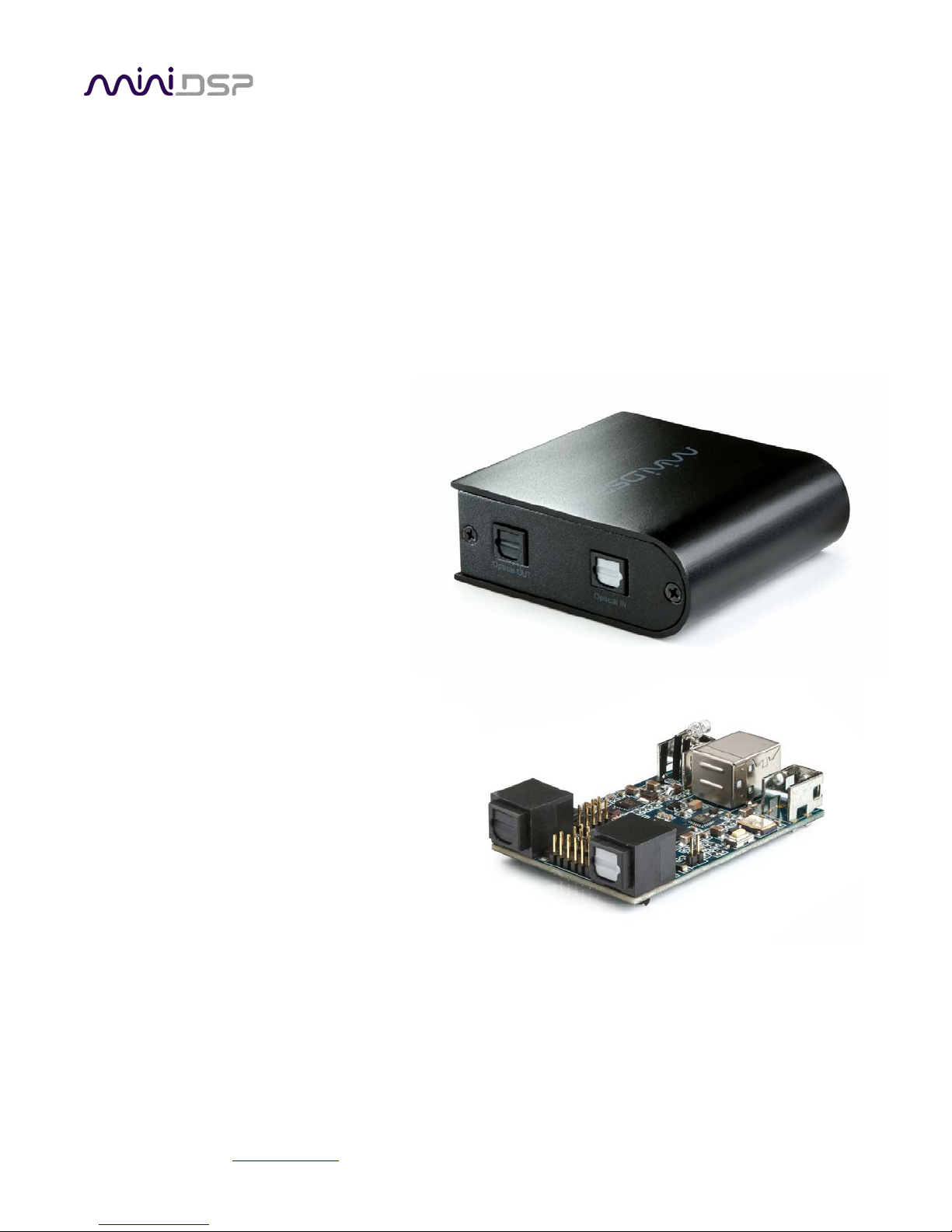
USBSTREAMER
10-CHANNEL USB AUDIO INTERFACE
TOSLINK/ADAT
BOX VERSION
I2S/TOSLINK/ADAT
KIT VERSION
User Manual
miniDSP Ltd, Hong Kong / www.minidsp.com / Features and specifications subject to change without prior notice 1
Page 2
Revision
Description
Date
1.0
User manual – Initial version
20-06-2012
1.1
Mac OSx configuration
09-08-2012
1.2
Adding USBStreamer B information + Win8 setup
26-05-2014
1.3
Updated installation procedure, Mac firmware update
22 March 2016
1.4
More detailed I2S information
25 March 2016
1.5
TDM firmware details
28 Aug 2017
Revision history
miniDSP Ltd, Hong Kong / www.minidsp.com / Features and specifications subject to change without prior notice 2
Page 3

TABLE OF CONTENTS
Important Information ...............................................................................................................................................4
System Requirements – Windows ..........................................................................................................................4
System Requirements – Mac OS X..........................................................................................................................4
Disclaimer/Warning ................................................................................................................................................4
Warranty Terms ......................................................................................................................................................4
FCC Class B Statement ............................................................................................................................................4
CE Mark Statement .................................................................................................................................................5
A Note on this Manual ............................................................................................................................................5
1 Product Overview ................................................................................................................................................6
1.1 Firmware versions ......................................................................................................................................6
2 Connectivity .........................................................................................................................................................7
2.1 USB and optical (box and kit versions) .......................................................................................................7
2.2 I2S/TDM connectivity (kit version only) .....................................................................................................7
2.2.1 I2S/TDM Pinouts .................................................................................................................................8
2.2.2 I2S Clock lines .....................................................................................................................................9
2.2.3 TDM Clock lines ..................................................................................................................................9
2.2.4 I2S Data lines ......................................................................................................................................9
2.2.5 External power ................................................................................................................................ 10
3 Installation and Configuration – Windows ....................................................................................................... 11
3.1 Download ................................................................................................................................................ 11
3.2 USB driver installation ............................................................................................................................. 11
3.3 Loading firmware ..................................................................................................................................... 12
3.4 USBStreamer Control Panel ..................................................................................................................... 14
3.4.1 Status ............................................................................................................................................... 14
3.4.2 Format ............................................................................................................................................. 14
3.4.3 Clock source ..................................................................................................................................... 15
3.4.4 Buffer settings ................................................................................................................................. 15
3.4.5 Volume............................................................................................................................................. 16
3.4.6 Info ................................................................................................................................................... 17
4 Installation and Configuration – Mac OS X ....................................................................................................... 18
4.1 Loading firmware ..................................................................................................................................... 18
4.2 Configuration in Audio MIDI Setup ......................................................................................................... 21
4.2.1 I2S_TOSLINK firmware ..................................................................................................................... 21
4.2.2 ADAT_I2S firmware ......................................................................................................................... 23
4.2.3 LowSampleRate firmware ............................................................................................................... 24
5 Additional Information ..................................................................................................................................... 25
5.1 Specifications ........................................................................................................................................... 25
5.2 Obtaining support .................................................................................................................................... 25
miniDSP Ltd, Hong Kong / www.minidsp.com / Features and specifications subject to change without prior notice 3
Page 4

IMPORTANT INFORMATION
Please read the following information before use. In case of any questions, please contact miniDSP via the support
portal at minidsp.desk.com
SYSTEM REQUIREMENTS – WINDOWS
• 1GHz or higher processor clock speed recommended / Intel® Pentium®/Celeron® family, or AMD K6®/AMD
Athlon®/AMD Duron® family, or compatible processor recommended.
• 512 megabytes (MB) of RAM or higher recommended
• One free USB 2.0 port
• Microsoft• ® Windows® XP SP2/Vista/Win7/Win8/Win10
SYSTEM REQUIREMENTS – MAC OS X
• Intel Core Duo processor or greater
• 256 megabytes (MB) of RAM or higher recommended
• One free USB 2.0 port
.
• Mac OS X 10.8 or greater
DISCLAIMER/WARNING
miniDSP cannot be held responsible for any damage that may result from the improper use or incorrect
configuration of this product. Please read this manual carefully to ensure that you fully understand how to operate
and use this product, as incorrect use or use beyond the parameters and ways recommended in this manual have
the potential to cause damage to your audio system.
Please also note that many of the questions we receive at the technical support department are already answered in
this User Manual and in the online application notes
carefully read this user manual and the online technical documentation. Thank you for your understanding!
on the miniDSP.com website. So please take the time to
WARRANTY TERMS
miniDSP Ltd warrants this product to be free from defects in materials and workmanship for a period of one year
from the invoice date. Our warranty does not cover failure of the product due to incorrect connection or installation,
improper or undocumented use, unauthorized servicing, modification or alteration of the unit in any way, or any
usage outside of that recommended in this manual. If in doubt, contact miniDSP prior to use.
FCC CLASS B STATEMENT
This device complies with Part 15 of the FCC Rules. Operation is subject to the following two conditions:
• This device may not cause harmful interference.
• This device must accept any interference received, including interference that may cause undesired operation.
miniDSP Ltd, Hong Kong / www.minidsp.com / Features and specifications subject to change without prior notice 4
Page 5

Warning: This equipment has been tested and found to comply with the limits for a Class B digital device, pursuant
to Part 15 of the FCC Rules. These limits are designed to provide reasonable protection. This equipment generates,
uses and can radiate radio frequency energy and, if not installed and used in accordance with the instructions, may
cause interference to radio communications. However, there is no guarantee that interference will not occur in a
particular installation. If this equipment does cause harmful interference to radio or television reception, which can
be determined by turning the equipment off and on, the user is encouraged to try to correct the interference by one
or more of the following measures:
• Reorient or relocate the receiving antenna.
• Increase the separation between the equipment and receiver.
• Connect the equipment into an outlet on a circuit different from that to which the receiver is connected.
• Consult the dealer or an experienced radio/TV technician for help.
Notice: Shielded interface cable must be used in order to comply with emission limits.
Notice: Changes or modification not expressly approved by the party responsible for compliance could void the
user’s authority to operate the equipment.
CE MARK STATEMENT
The USBSTREAMER has passed the test performed according to European Standard EN 55022 Class B.
A NOTE ON THIS MANUAL
This User Manual is designed for reading in both print and on the computer. If printing the manual, please print
double-sided. The embedded page size is 8 ½” x 11”. Printing on A4 paper will result in a slightly reduced size.
For reading on the computer, we have included hyperlinked cross-references throughout the manual. In addition, a
table of contents is embedded in the PDF file. Displaying this table of contents will make navigation much easier:
• In Adobe Reader on Windows, click on the “bookmarks” icon at the left. The table of contents will appear on the
left and can be unfolded at each level by clicking on the “+” icons.
• In Preview on the Mac, click on the View menu and select Table of Contents. The table of contents will appear on
the left and can be unfolded at each level by clicking on the triangle icons.
miniDSP Ltd, Hong Kong / www.minidsp.com / Features and specifications subject to change without prior notice 5
Page 6

1 PRODUCT OVERVIEW
Thank you for purchasing a miniDSP USBStreamer USB audio interface. The USBStreamer comes in two versions.
The box version can be used in two modes by loading different firmware:
• Eight channels of input/output via optical (ADAT) connectors (this is the default when the USBStreamer B box
version is shipped from miniDSP), or
• Two channels (stereo) input/output via optical (TOSLINK) connectors
The kit version can be used in three modes:
• Eight channels of input/output via I2S header pins, and two channels of input/output via optical (TOSLINK)
connectors (this is the default when the USBStreamer kit board is shipped from miniDSP), or
• Eight channels of input/output via optical (ADAT) connectors, or
• Eight channels of input/output via I2S header pins, with support for sample rates as low as 8 kHz
Typical applications for the USBStreamer include hi-fi systems and recording studios. The kit version can be built into
multichannel DACs, ADCs and digital audio interfaces, with connection to the USBStreamer via the I2S headers.
1.1 FIRMWARE VERSIONS
The function of the USBStreamer depends on the specific firmware version loaded into it. There are three firmware
versions in the software download zip file. Please confirm that your USBStreamer has the correct firmware for your
application prior to use.
ADAT
These versions of the firmware will receive and transmit eight channels of audio in ADAT format via
the input and output optical connectors. The sample rate can be 44.1 or 48 kHz. This is the firmware
loaded into the USBStreamer B (box version) when it is shipped from miniDSP.
I2S/TOSLINK
These versions of the firmware will receive and transmit eight channels of audio over the I2S
headers and two channels over the optical connectors. The sample rate can be 44.1, 48, 88.2, 96,
176.4, or 192 kHz. (All channels must run at the same sample rate.) This is the firmware loaded into
the USBStreamer circuit board (kit version) when it is shipped from miniDSP.
Low Sample Rate
These versions of the firmware will receive and transmit eight channels of audio over the I2S
headers. (The optical connectors are not active.) They will support low sample rates, down to 8 kHz,
as well as all standard sample rates up to 192 kHz.
TDM
The Time Division Multiplexing (TDM) format packetizes multiple channels of audio in one frame. It’s
similar to I2S but in multichannel .The TDM format is for 8ch audio in/out at 44.1/48k.
Each firmware version includes files with two different IDs. If two USBStreamers are to be connected to the same
computer, make sure that each has firmware with a different ID.
miniDSP Ltd, Hong Kong / www.minidsp.com / Features and specifications subject to change without prior notice 6
Page 7
2 CONNECTIVITY
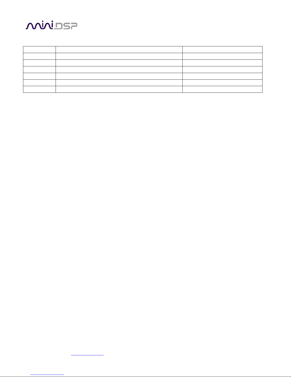
2.1 USB AND OPTICAL (BOX AND KIT VERSIONS)
Connect as shown (for either box or kit version). The optical input and output will receive and transmit either stereo
SPDIF or 8-channel ADAT, depending on the loaded firmware.
2.2 I2S/TDM CONNECTIVITY (KIT VERSION ONLY)
I2S, or Inter-IC Sound, is a simple protocol used to carry digital audio information between digital chips (ICs) and
circuit boards. The USBStreamer circuit board provides 8 channels of I2S input and 8 channels of I2S output via a 12pin header. All channels can operate simultaneously at sample rates of up to 192 kHz. I2S pinouts are shown on the
next page.
Please note that I2S connectivity is intended for advanced DIY use only. You will need the knowledge to understand
digital clocking and wiring, and have access to the equipment necessary to be able to debug any issues you may run
into. (While miniDSP always tries to help its customers, it is infeasible for us to debug your circuit and wiring for
you.)
Be sure to take the following precautions when designing your I2S interface and wiring:
General I2S usage notes
• Unbuffered I2S lines must be kept short to ensure clock and data integrity.
• If driving longer lines, buffers may be required for the clock signals (MCLK, LRCLK, and BLCK).
• Observe correct grounding and shielding, and keep analog and digital grounds separated.
• Ensure that the clock ratios (as listed on the next page) are compatible with connected circuits.
Clock master
The USBStreamer always operates as clock master – that is, the clock lines are always outputs. The connected
circuitry must therefore use the clocks provided by the USBStreamer.
3.3V logic level
All lines use a 3.3V logic level. Ensure that connected circuits use a compatible level (1.8V, for example, will not
work).
miniDSP Ltd, Hong Kong / www.minidsp.com / Features and specifications subject to change without prior notice 7
Page 8

Pin
Description
Pin
Description
1
I2S data OUT Ch 1&2 / TDM Out
1 Ground (GND)
2
I2S data IN Ch 1&2 / TDM In
2 NC 3 I2S data OUT Ch 3&4
3 Ground (GND)
4
I2S data IN Ch 3&4
4 NC 5 I2S data OUT Ch 5&6
5 NC
6
I2S data IN Ch 5&6
6 GPIO (future)
7
I2S data OUT Ch 7&8
7 GPIO (future)
8
I2S data IN Ch 7&8
8 RST (negative low)
9
Master clock (MCLK OUT)
9 GPIO (future)
10
Bit clock out (BCLK)
10
GPIO (future)
11
Ground (GND)
11
Ground (GND)
12
I2S frame sync (LRCLK)
12
5V external power
2.2.1 I2S/TDM Pinouts
The USBStreamer circuit board has two 12-pin headers located between the optical ports. All I2S lines are on J1,
while J2 carries auxiliary signaling and GPIO lines reserved for future enhancement. The I2S lines are explained in
detail on the next page.
Note that all I2S lines are 3.3V logic levels. Connected circuits must use a compatible logic level.
miniDSP Ltd, Hong Kong / www.minidsp.com / Features and specifications subject to change without prior notice 8
Page 9

Sample rate (LRCLK)
Master clock (MCLK)
Bit clock (BCLK)
MCLK/LRCLK
BCLK/LRCLK
44.1 kHz
22.5792 MHz
2.822 MHz
512
64
48 kHz
24.576 MHz
3.072 MHz
512
64
88.2 kHz
22.5792 MHz
5.6448 MHz
256
64
96 kHz
24.576 MHz
6.144 MHz
256
64
176.4 kHz
22.5792 MHz
11.2896 MHz
128
64
192 kHz
24.576 MHz
12.288 MHz
128
64
Sample rate (LRCLK)
Master clock (MCLK)
Bit clock (BCLK)
MCLK/LRCLK
BCLK/LRCLK
44.1 kHz
22.5792 MHz
11.2896 MHz
512
64
48 kHz
24.576 MHz
12.288 MHz
512
64
2.2.2 I2S Clock lines
There are three clock lines. These clocks are always outputs. The connected circuitry must therefore be set to run in
slave mode and accept its clocks from the USBStreamer. (The USBStreamer always runs as clock master; it cannot be
set to run as a slave.)
MCLK The master clock for both playback and recording. This pin is an output only.
LRCLK The frame synchronization clock, also known as the word clock. This clock is equal to the sampling
frequency (Fs) of the audio signal. This pin is an output only.
BCLK The bit clock (also known as shift clock or system clock). This is always equal to 64 x Fs. This pin is an
output only.
The following table summarizes the relation between the clocks. Be sure to double-check that connected circuitry
will accept the clocks at the frequencies and ratios listed here:
2.2.3 TDM Clock lines
The clock lines are the same as per I2S above. Just a different clock rate.
2.2.4 I2S Data lines
There are four lines for input data, and four line for output data (as indicated in the pinout on the previous page).
Each line carries two audio channels, in either 16-bit or 24-bit format. The expected I2S data format and timing is
shown in this diagram:
miniDSP Ltd, Hong Kong / www.minidsp.com / Features and specifications subject to change without prior notice 9
Page 10

2.2.5 External power
External 5V DC power can be connected to the USBStreamer via pin 12 of J2. This pin is connected with a “diode-or”
connection to the power line from the USB port. Supplying 5V DC to this pin will therefore ensure that the
USBStreamer remains powered on even when no USB device is connected.
miniDSP Ltd, Hong Kong / www.minidsp.com / Features and specifications subject to change without prior notice 10
Page 11

3 INSTALLATION AND CONFIGURATION – WINDOWS
Please read and follow all steps in this section carefully.
3.1 DOWNLOAD
The USBSTREAMER is a USB Audio Class 2.0 device. For use with Microsoft Windows, driver installation is required.
When you receive notification that your order has shipped, your installation software download will be available at
the User Downloads section of the miniDSP website:
http://www.minidsp.com/userdownloads
(If you are unable to access this section of the website, please log in first.)
Download the installation zip file under the USB Streamer Driver heading and unzip the folder on your PC.
3.2 USB DRIVER INSTALLATION
The USB driver enables Windows to stream audio to the USBStreamer. In addition, it installs a control panel to help
manage the USBStreamer, and the firmware updater necessary to load the most suitable firmware version.
To install the driver, the USBStreamer must be connected to the computer by USB. Go to the WinDrivers folder of
the installation download and double-click on the appropriate installer:
• miniDSP_UAC2_v2.29.0_ForWinXP_Vista.exe for Windows XP and Vista
• miniDSP_UAC2_v3.34.0_ForWin7_8_10.exe for Windows 7, 8, and 10
(The version number embedded in the filename may be different.)
We recommend accepting the default installation location. Once the driver installation completes, click the Finish
button.
The Windows PC will not be able to communicate properly with the USBStreamer if you did not have the
USBStreamer connected by USB when you ran the installer. If that is the case, you will need to uninstall
the driver, connect the USBStreamer, and run the installer again.
miniDSP Ltd, Hong Kong / www.minidsp.com / Features and specifications subject to change without prior notice 11
Page 12

3.3 LOADING FIRMWARE
If the default firmware loaded into your USBStreamer as shipped is not suited for your application, you will need to
load a different firmware version. (You do not need to load firmware if the default firmware is suitable for your
application.)
• USBStreamer B (box) has ADAT firmware loaded when shipped.
• USBStreamer kit has TOSLINK/I2S firmware loaded when shipped.
To load a different firmware version:
1. Connect the USBStreamer to your computer via USB (if not already connected).
2. Browse to the Firmware\miniDSP_UAC2_DFU\ under the driver zip file. Start the miniDSPUAC2Dfu.exe
3. The firmware update program will start:
miniDSP Ltd, Hong Kong / www.minidsp.com / Features and specifications subject to change without prior notice 12
Page 13

4. Click on the Browse button and navigate to the plugin download folder and then the Firmware folder. Select
the most suitable firmware file according to your application. Below are the folder names. Each folder has two
different files, identical except for ID number, so that two USBStreamers can be connected to the one
computer:
ADAT_I2S
These files will receive and transmit eight channels of audio in ADAT format via the input and output
optical connectors. The sample rate can be 44.1 or 48 kHz.
I2S_TOSLINK
These files will receive and transmit eight channels of audio over the I2S headers, and two channels
over the optical connectors. The sample rate can be 44.1, 48, 88.2, 96, 176.4, or 192 kHz. (All
channels must run at the same sample rate.)
LowSampleRate
These files are will receive and transmit eight channels of audio over the I2S headers. (The optical
connectors are not active.) They will support low sample rates, down to 8 kHz.
TDM
These files are will receive and transmit eight channels of audio over the TDM headers. (The optical
connectors are not active.) They will support of 48/44.1kHz
5. Click on the Start button.
6. You will get a progress bar as upgrade proceeds. When it completes, you will see a message that the upgrade
completed successfully:
7. Click on Exit.
8. That’s it! You’re done. You can now use your USBStreamer.
miniDSP Ltd, Hong Kong / www.minidsp.com / Features and specifications subject to change without prior notice 13
Page 14

3.4 USBSTREAMER CONTROL PANEL
To configure the USBStreamer, open the miniDSP UAC2 Control Panel (from Start Menu -> miniDSP Ltd). It has
several panes, described below.
3.4.1 Status
This panel shows the current sample rate of the USBStreamer. This setting cannot be changed in the Control panel,
but simply reflects the current sample rate of the USBStreamer.
3.4.2 Format
This panel is present only if the ADAT firmware is loaded. Be sure to always have 8-channel input and output
selected here.
miniDSP Ltd, Hong Kong / www.minidsp.com / Features and specifications subject to change without prior notice 14
Page 15

3.4.3 Clock source
This panel allows you to select the clock source: internally generated by the USBStreamer and selected by the
computer, or generated from the TOSLINK (or ADAT) input.
3.4.4 Buffer settings
The buffer settings are for those looking to optimize the buffering and latency settings of the interface. Note that
changing these settings may result in unstable operation since such changes are dependent on the resources of the
PC. For example, the lowest latency settings require high amounts of CPU and memory, and may not work on some
machines. If you do not require lowest latency, we recommend that you do not depart from the default safe
settings.
miniDSP Ltd, Hong Kong / www.minidsp.com / Features and specifications subject to change without prior notice 15
Page 16

3.4.5 Volume
This panel contains a master volume control for all eight output channels, and individual level controls for each
channel or pair of channels.
o To reset the master volume control or a pair of channels to 0 dB (no attenuation), click the 0dB button.
o To mute all channels, click the speaker icon above “MASTER”.
o To mute a pair of channels, click the speaker icon above the label.
o To control volume separately for each channel, click on the “Link” icon to turn it off.
There is a similar set of controls for the input channels:
miniDSP Ltd, Hong Kong / www.minidsp.com / Features and specifications subject to change without prior notice 16
Page 17
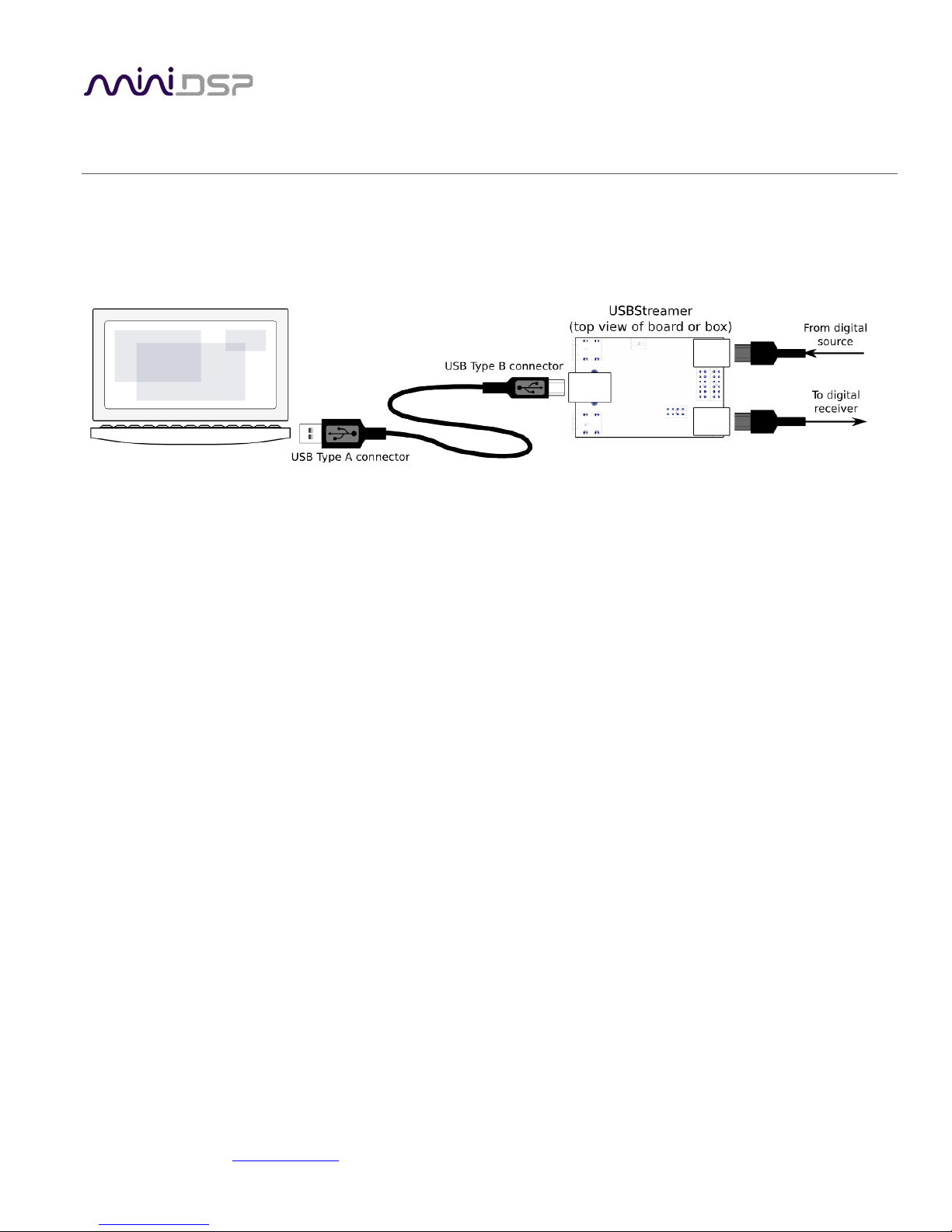
3.4.6 Info
This pane shows information about the USBStreamer.
miniDSP Ltd, Hong Kong / www.minidsp.com / Features and specifications subject to change without prior notice 17
Page 18

4 INSTALLATION AND CONFIGURATION – MAC OS X
Mac OS X has native support for USB Audio class 2.0 devices, so no driver installation is required. The USBSTREAMER
will automatically be detected by Mac OS X as a compliant multichannel USB audio interface. However, depending
on your application, you may need to load different firmware.
4.1 LOADING FIRMWARE
If the default firmware loaded into your USBStreamer as shipped is not suited for your application, you will need to
load a different firmware version. (You do not need to load firmware if the default firmware is suitable for your
application.)
• USBStreamer B (box) has ADAT firmware loaded when shipped.
• USBStreamer Kit has TOSLINK/I2S firmware loaded when shipped.
To load firmware using Mac OS X requires that you use the Terminal program (located in the Applications/Utilities
folder). In the examples that follow, black text is the “prompt” printed by Terminal, blue text is text typed in by you,
and red text is the program output.
It is important that you type exactly as shown including characters like “.” and “/” where noted (the
firmware version numbers may be different). Press the Tab key after typing the first two characters of
any filename, to activate auto-completion.
Download the latest software for the USBStreamer from the User Downloads area of the minidsp.com website.
Double-click on it to unzip it. Assuming you have placed it into the Downloads folder on your Mac, you will then
type:
mymac:~ myname$ cd Downloads/USBStreamer_20160225/Firmware/
mymac:Firmware myname $ ls
ADAT_I2S LowSampleRate miniDSP_UAC2_DFU_OSX
I2S_TOSLINK UDAC8 readme.txt
mycomputer:Firmware myname $
The firmware files are located in the folders ADAT_I2S, LowSampleRate, and I2S_TOSLINK. Here is a list of those
files:
mymac:Firmware myname $ ls ADAT_I2S/ LowSampleRate/ I2S_TOSLINK/
ADAT_I2S/:
USBStreamer_Up_ADAT_v5_ID3.bin USBStreamer_Up_ADAT_v5_ID4.bin
I2S_TOSLINK/:
USBStreamer_Up_TOSLINK_v5_ID1.bin USBStreamer_Up_TOSLINK_v5_ID2.bin
LowSampleRate/:
USBStreamer_Up_LowRate_v4_ID5.bin USBStreamer_Up_LowRate_v4_ID6.bin
mymac:Firmware myname $
miniDSP Ltd, Hong Kong / www.minidsp.com / Features and specifications subject to change without prior notice 18
Page 19

The choice of firmware affects the operation of the USBStreamer, as follows. In each case, there are two different
files, identical except for ID number, so that two USBStreamers can be connected to the one computer.
ADAT_I2S
These files will receive and transmit eight channels of audio in ADAT format via the input and output
optical connectors. The sample rate can be 44.1 or 48 kHz.
I2S_TOSLINK
These files will receive and transmit eight channels of audio over the I2S headers, and two channels
over the optical connectors. The sample rate can be 44.1, 48, 88.2, 96, 176.4, or 192 kHz. (All
channels must run at the same sample rate.)
LowSampleRate
These files will receive and transmit eight channels of audio over the I2S headers. (The optical
connectors are not active.) They will support low sample rates, down to 8 kHz.
TDM
These files are will receive and transmit eight channels of audio over the TDM headers. (The optical
connectors are not active.) They will support of 48/44.1kHz
Now you will need to copy your chosen firmware file into the miniDSP_UAC2_DFU_OSX folder, and then change to
that folder, like this:
mymac:Firmware myname$ cp I2S_TOSLINK/USBStreamer_Up_TOSLINK_v5_ID1.bin miniDSP_UAC2_DFU_OSX/
mymac:Firmware myname$ cd miniDSP_UAC2_DFU_OSX/
mymac:miniDSP_UAC2_DFU_OSX myname $
Then run the firmware updater, like this:
mymac:miniDSP_UAC2_DFU_OSX myname $ source setup.sh
mymac:miniDSP_UAC2_DFU_OSX myname $ ./xmosdfu --download USBStreamer_Up_TOSLINK_v5_ID1.bin
VID = 0x5ac, PID = 0x8007, BCDDevice: 0x300
VID = 0x5ac, PID = 0x8007, BCDDevice: 0x300
...
VID = 0x5ac, PID = 0x259, BCDDevice: 0x224
VID = 0x2752, PID = 0x16, BCDDevice: 0x530
XMOS DFU application started - Interface 3 claimed
Detaching device from application mode.
Waiting for device to restart and enter DFU mode...
VID = 0x5ac, PID = 0x8007, BCDDevice: 0x300
VID = 0x5ac, PID = 0x8007, BCDDevice: 0x300
...
VID = 0x5ac, PID = 0x259, BCDDevice: 0x224
VID = 0x2752, PID = 0x16, BCDDevice: 0x530
... DFU firmware upgrade device opened
... Downloading image (USBStreamer_Up_TOSLINK_v5_ID1.bin) to device
... Download complete
... Returning device to application mode
mymac:miniDSP_UAC2_DFU_OSX myname $
miniDSP Ltd, Hong Kong / www.minidsp.com / Features and specifications subject to change without prior notice 19
Page 20

You can now proceed to check the configuration of the USBStreamer with Audio MIDI Setup, as described in the
next section.
miniDSP Ltd, Hong Kong / www.minidsp.com / Features and specifications subject to change without prior notice 20
Page 21

4.2 CONFIGURATION IN AUDIO MIDI SETUP
4.2.1 I2S_TOSLINK firmware
Open the program Audio MIDI Setup (in Applications->Utilities). Click on the device USBStreamer that appears in
the list of devices on the left to show the eight I2S and two TOSLINK output channels:
Clicking the Input button will show the equivalent input channels. This example also shows the sample rates
supported:
miniDSP Ltd, Hong Kong / www.minidsp.com / Features and specifications subject to change without prior notice 21
Page 22

By default, the sample rate clock of the USBStreamer is internally derived, but it can also be derived from the
TOSLINK input by using the Clock Source selector:
If you are using software that is able to route audio to ten different channels, no further configuration is needed. If,
however, you would like the TOSLINK output to be the default stereo output for all applications, then:
1. Click on USBSTREAMER and then the Output button.
2. Click on the Configure Speakers button. Select the Stereo button. For the left channel, select Channel 9, and
for the right channel, select Channel 10. Then click Apply and then click Done.
3. Select the output sample rate. Typically, 44.1 kHz is the best choice. Some audio players will automatically
change this setting according to the media being played.
4. To set the USBSTREAMER to be the default audio output device, right-click and select “Use this device for
sound output”.
miniDSP Ltd, Hong Kong / www.minidsp.com / Features and specifications subject to change without prior notice 22
Page 23

4.2.2 ADAT_I2S firmware
Open the program Audio MIDI Setup (in Applications->Utilities). Click on the device USBStreamer that appears in
the list of devices on the left, to show the eight ADAT output channels. As shown in this example, the sample rate
can be selected for 44.1 or 48 kHz:
Clicking on the Input button will likewise show the eight ADAT input channels.
By default, the sample rate clock is generated internally by the USBStreamer. It can be set to use the incoming ADAT
clock, by selecting the option from the Clock source dropdown:
miniDSP Ltd, Hong Kong / www.minidsp.com / Features and specifications subject to change without prior notice 23
Page 24

If more than eight ADAT channels are required, use two USBStreamers and load firmware with different IDs into
each. (That is, load ID3 into one USBStreamer and ID4 into the other.) Depending on the specifics of your system
setup (DAW, external hardware, etc.), you can create a 16-channel aggregate device in Audio MIDI Setup:
4.2.3 LowSampleRate firmware
Open the program Audio MIDI Setup (in Applications->Utilities). Click on the device USBStreamer that appears in
the list of devices on the left, to show the eight I2S output and input channels. The Format dropdown provides
selection of sample rates down to 8 kHz:
miniDSP Ltd, Hong Kong / www.minidsp.com / Features and specifications subject to change without prior notice 24
Page 25

5 ADDITIONAL INFORMATION
5.1 SPECIFICATIONS
Computer connectivity USB 2.0, USB Audio Class 2 compliant
Driver Mac OS X: no driver required
Windows: driver provided
Audio sample rate IS2/TOSLINK mode: 44.1 to 192 kHz (10 channels )
ADAT mode: 44.1 or 48 kHz (8 channels)
Low sample rate mode: 8 to 192 kHz (8 channels)
Audio resolution 24-bit integer
Enclosure Aluminum, sand blasted and anodized (USBStreamer B only)
Power supply USB-powered
Dimensions (H x W x D) 13 x 40 x 62 mm (USBStreamer)
24 x 64 x 67.4 mm (USBStreamer B)
5.2 OBTAINING SUPPORT
1. Check the forums on miniDSP.com to see if this issue has already been raised and a solution or solutions
provided.
2. Contact miniDSP via the support portal at minidsp.desk.com
a. The product information including OS version and version of driver installed (for Windows).
b. A clear explanation of the symptoms you are seeing.
c. A description of the troubleshooting steps you performed and the results obtained.
with:
miniDSP Ltd, Hong Kong / www.minidsp.com / Features and specifications subject to change without prior notice 25
 Loading...