

miniDSP Ltd, Hong Kong / www.minidsp.com / Features and specifications subject to change without prior notice 1
SPK-4P
COMPACT DSP-ENABLED IP SPEAKER
SPK-4
AUXILIARY PASSIVE SPEAKER
User Manual

miniDSP Ltd, Hong Kong / www.minidsp.com / Features and specifications subject to change without prior notice 2
Revision history
Revision
Description
Date
1.0
First released version
4th June 2019
1.1
Updated for configurations/presets, added panel diagram
17th June 2019

miniDSP Ltd, Hong Kong / www.minidsp.com / Features and specifications subject to change without prior notice 3
TABLE OF CONTENTS
Important Information ...............................................................................................................................................5
1 Product Overview ................................................................................................................................................7
1.1 Typical application ......................................................................................................................................7
1.2 About AVB ..................................................................................................................................................8
2 Hardware Connectivity ........................................................................................................................................9
3 AVB Configuration – Mac OS X ......................................................................................................................... 10
3.1 Enabling AVB speaker .............................................................................................................................. 10
3.2 Configuring multiple SPK-4P .................................................................................................................... 11
4 Software installation ......................................................................................................................................... 14
4.1 Mac .......................................................................................................................................................... 15
4.2 Possible Mac installation issues .............................................................................................................. 15
4.3 2x4 HD plugin installation ........................................................................................................................ 15
5 Configuring the SPK-4P ..................................................................................................................................... 16
5.1 Signal flow and processing overview ....................................................................................................... 16
5.2 Synchronizing with the SPK-4P ................................................................................................................ 17
5.3 Key features ............................................................................................................................................. 18
5.3.1 Master control ................................................................................................................................. 18
5.3.2 Configuration/preset selection........................................................................................................ 18
5.3.3 Saving and loading configurations ................................................................................................... 18
5.3.4 Restoring to defaults ....................................................................................................................... 19
5.3.5 Local configuration storage ............................................................................................................. 19
5.3.6 Input selection ................................................................................................................................. 19
5.4 Input channel strips ................................................................................................................................. 20
5.5 Routing .................................................................................................................................................... 21
5.6 Output tab ............................................................................................................................................... 22
5.6.1 Channel strip layout ......................................................................................................................... 22
5.6.2 Channel label ................................................................................................................................... 22
5.6.3 Level meter and gain control ........................................................................................................... 22
5.6.4 Parametric EQ .................................................................................................................................. 23
5.6.5 Crossover ......................................................................................................................................... 25
5.6.6 Compressor ...................................................................................................................................... 27
5.6.7 FIR .................................................................................................................................................... 28
5.6.8 Invert and mute ............................................................................................................................... 28
5.6.9 Time delay ....................................................................................................................................... 28
5.7 Custom biquad programming .................................................................................................................. 29
5.7.1 What’s a “biquad? ........................................................................................................................... 29
5.7.2 Using custom biquad programming ................................................................................................ 29
5.7.3 Biquad design software ................................................................................................................... 31
5.8 FIR filtering and design ............................................................................................................................ 32
5.8.1 FIR filtering overview ....................................................................................................................... 33
5.8.2 FIR filter design software ................................................................................................................. 33

miniDSP Ltd, Hong Kong / www.minidsp.com / Features and specifications subject to change without prior notice 4
5.8.3 Filter file format ............................................................................................................................... 33
5.8.4 Loading filter coefficients ................................................................................................................ 34
5.9 Keyboard shortcuts ................................................................................................................................. 34
6 Additional information ...................................................................................................................................... 35
6.1 Specifications ........................................................................................................................................... 35
6.2 Obtaining support .................................................................................................................................... 35

miniDSP Ltd, Hong Kong / www.minidsp.com / Features and specifications subject to change without prior notice 5
IMPORTANT INFORMATION
Please read the following information before use. In case of any questions, please contact miniDSP via the
support portal at minidsp.desk.com.
System Requirements – Windows
Use of the SPK-4P is currently not supported on Windows.
System Requirements – Mac OS X
• Intel-based Mac with 1 GHz or higher processor clock speed
• 512 megabytes (MB) of RAM or higher recommended
• OS X 10.9 or higher, macOS 10.12 or higher
• Ethernet network connection
Disclaimer/Warning
miniDSP cannot be held responsible for any damage that may result from the improper use or incorrect
configuration of this product. Please read this manual carefully to ensure that you fully understand how to
operate and use this product, as incorrect use or use beyond the parameters and ways recommended in this
manual have the potential to cause damage to your audio system.
Please also note that many of the questions we receive at the technical support department are already
answered in this User Manual and in the online application notes on the miniDSP.com website. So please take
the time to carefully read this user manual and the online technical documentation. Thank you for your
understanding!
Warranty Terms
miniDSP Ltd warrants this product to be free from defects in materials and workmanship for a period of one
year from the invoice date. Our warranty does not cover failure of the product due to incorrect connection or
installation, improper or undocumented use, unauthorized servicing, modification or alteration of the unit in any
way, or any usage outside of that recommended in this manual. If in doubt, contact miniDSP prior to use.
FCC Class B Statement
This device complies with Part 15 of the FCC Rules. Operation is subject to the following two conditions:
• This device may not cause harmful interference.
• This device must accept any interference received, including interference that may cause undesired
operation.
Warning: This equipment has been tested and found to comply with the limits for a Class B digital device,
pursuant to Part 15 of the FCC Rules. These limits are designed to provide reasonable protection. This
equipment generates, uses and can radiate radio frequency energy and, if not installed and used in accordance
with the instructions, may cause interference to radio communications. However, there is no guarantee that
interference will not occur in a particular installation. If this equipment does cause harmful interference to radio

miniDSP Ltd, Hong Kong / www.minidsp.com / Features and specifications subject to change without prior notice 6
or television reception, which can be determined by turning the equipment off and on, the user is encouraged to
try to correct the interference by one or more of the following measures:
• Reorient or relocate the receiving antenna.
• Increase the separation between the equipment and receiver.
• Connect the equipment into an outlet on a circuit different from that to which the receiver is connected.
• Consult the dealer or an experienced radio/TV technician for help.
Notice: Shielded interface cable must be used in order to comply with emission limits.
Notice: Changes or modification not expressly approved by the party responsible for compliance could void the
user’s authority to operate the equipment.
CE Mark Statement
The SPK-4P has passed the test performed according to European Standard EN 55022 Class B.
A Note on this Manual
This User Manual is designed for reading in both print and on the computer. If printing the manual, please print
double-sided. The embedded page size is 8 ½” x 11”. Printing on A4 paper will result in a slightly reduced size.
For reading on the computer, we have included hyperlinked cross-references throughout the manual. In
addition, a table of contents is embedded in the PDF file. Displaying this table of contents will make navigation
much easier:
• In Adobe Reader on Windows, click on the “bookmarks” icon at the left. The table of contents will appear on
the left and can be unfolded at each level by clicking on the “+” icons.
• In Preview on the Mac, click on the View menu and select Table of Contents. The table of contents will
appear on the left and can be unfolded at each level by clicking on the triangle icons.
miniDSP Ltd, Hong Kong / www.minidsp.com / Features and specifications subject to change without prior notice 7
1 PRODUCT OVERVIEW
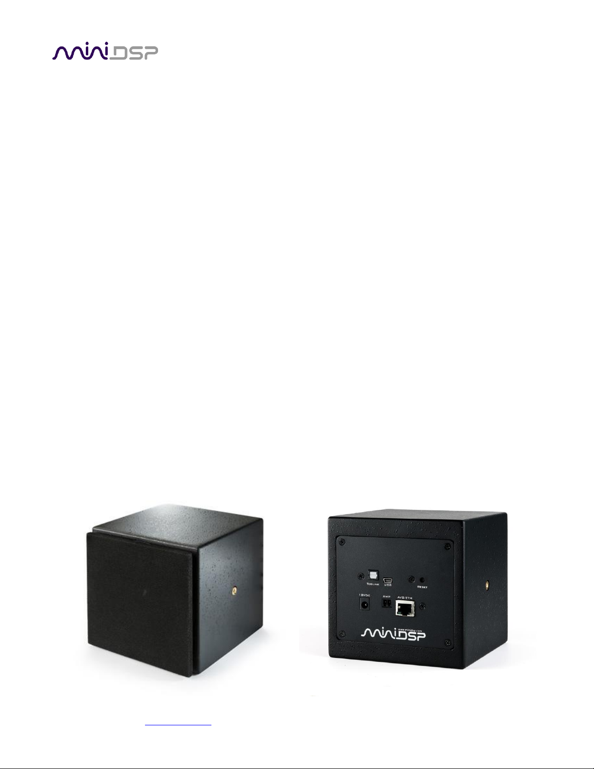
Thank you for purchasing the miniDSP SPK-4P DSP-enabled IP speaker and the auxiliary SPK-4 speaker for your
installation. The SPK-4P is a PoE+ full-range loudspeaker combining network audio streaming, Class D
amplification and a powerful Digital Signal Processor (DSP). A single CAT5/6 network cable provides power, low
latency audio and control.
Each SPK-4P provides two channels of power amplification, one for the internal driver and one for a connected
SPK-4 auxiliary speaker module.
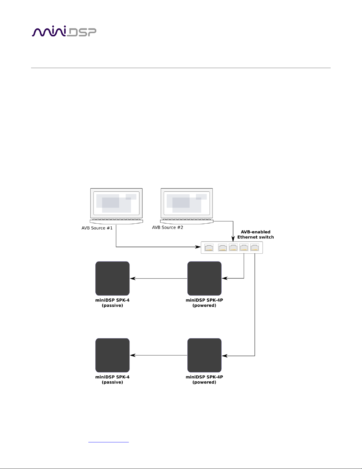
1.1 TYPICAL APPLICATION
The Ethernet port of the SPK-4P connects to any AVB-enabled Ethernet switch. Use of AVB allows for flexible
distributed audio applications in any setting. Each powered speaker can be provided with power either from a
12V DC supply or via Power-over-Ethernet.

miniDSP Ltd, Hong Kong / www.minidsp.com / Features and specifications subject to change without prior notice 8
1.2 ABOUT AVB
AVB defines a group of network protocols for the distribution of time-synchronized and low-latency audio &
video streams over IEEE802 networks. By leveraging a combination of existing 802 network technologies along
with standards specifically designed for the purpose, AVB technology lays the groundwork for unparalleled
guaranteed media streaming over Ethernet networks. The overall concept of AVB is actually rather simple. In
brief, the three core protocols specify:
1. Timing and synchronization
2. Bandwidth allocation through the Stream Reservation Protocol (SRP)
3. Traffic shaping to ensure that low priority Ethernet traffic does not interfere with AVB traffic.
Engineered from the ground up for media streaming applications, AVB has a definitive edge over legacy Ethernet
technology in the sense that it allows bandwidth allocation and priority rules based on timing. Unlike similar
audio over IP (AOIP) technology, AVB will dynamically assign and defend bandwidth allocation for AVB
streaming, thanks to the Stream Reservation Protocol (SRP).
These are the key terms used for AVB streaming:
Audio Video Bridging (AVB)
General descriptive for a group of protocols providing audio/ video streaming, timing,
synchronization, Quality of service (QoS), control and discovery.
AVB Endpoint
A device capable of transmitting and/ or receiving audio streams using the P1722/P1733
transport protocol.
Talker
An AVB endpoint transmitting audio to the network (source).
Listener
An AVB endpoint receiving audio from the network (sink/destination).
Talker/Listener
An AVB endpoint that is both transmitting and receiving.
Precision Time Protocol (PTP)
The protocol that allows devices on the network to get a notion of global time in order to
synchronize with each other. PTP components in each AVB module can act as a Grand Master
(providing clock) or as a slave (receiving clock). Once a grand master negotiates and is selected
as a sync source, all units will synchronize to it.
Stream ID
Unique 64-bit stream identifier used by AVB transport protocols to identify streams.
miniDSP Ltd, Hong Kong / www.minidsp.com / Features and specifications subject to change without prior notice 9
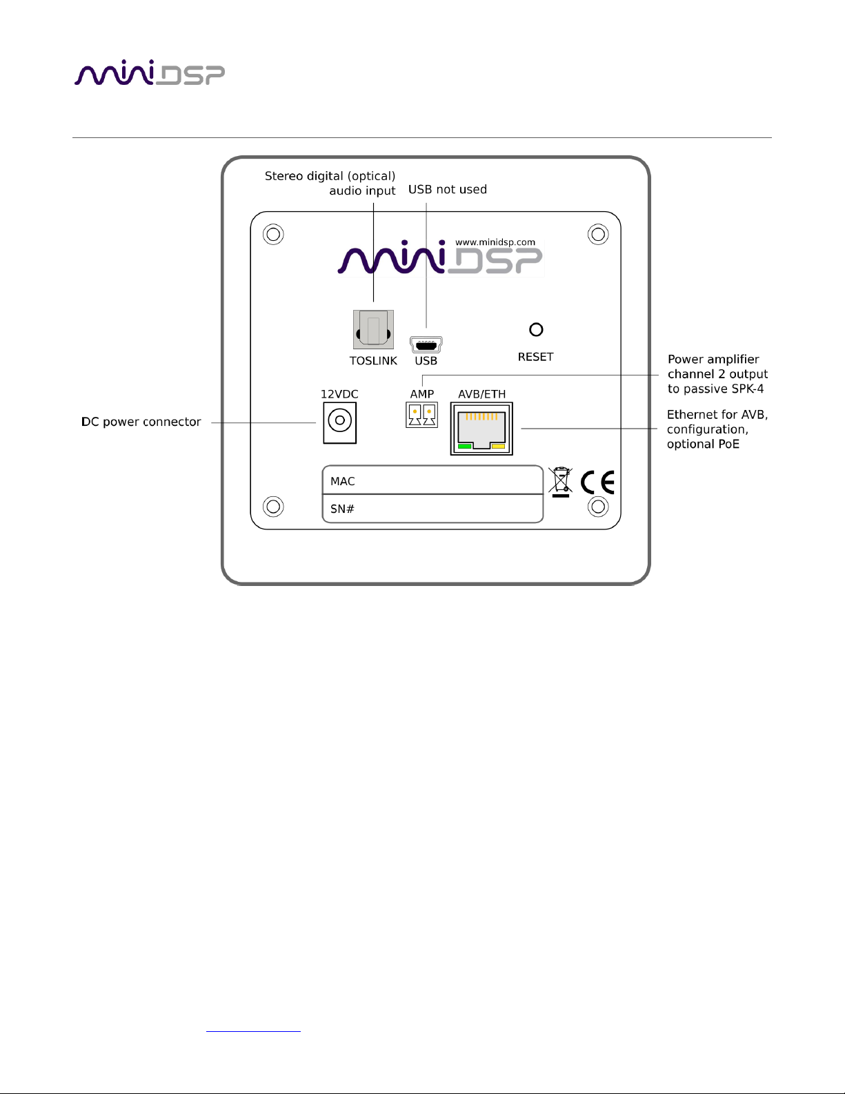
2 HARDWARE CONNECTIVITY
12VDC
12 VDC power input from external power supply. This separate 12 VDC connection is not used if
the speaker is powered over Ethernet (PoE).
USB
USB Audio is not supported for the default SPK-4P configuration. Contact miniDSP directly if you
require a USB-capable firmware for the SPK-4P.
TOSLINK
Digital optical input. Sample rates from 20 to 216 kHz are accepted.
AMP
The channel 2 output of the power amplifier is provided via this connector. Usually, this is
connected to a passive SPK-4.
AVB/ETH
Used for AVB audio and SPK-4P configuration. It must be connected to an AVB-capable switch. If
the switch provides PoE (Power over Ethernet), then the speaker is powered from this connector
and the 12VDC connector is not used.
miniDSP Ltd, Hong Kong / www.minidsp.com / Features and specifications subject to change without prior notice 10
3 AVB CONFIGURATION – MAC OS X
Mac OS X 10.9 or later and macOS 10.12 or later natively support AVB, so no driver installation is required.
miniDSP does not currently support use of the SPK-4P with Windows.
Versions of OS X prior to 10.9 do not have inbuilt AVB support. While it may be possible to use third-party
drivers, please note that miniDSP does not support operation of the SPK-4P with earlier versions of OS X.
3.1 ENABLING AVB SPEAKER
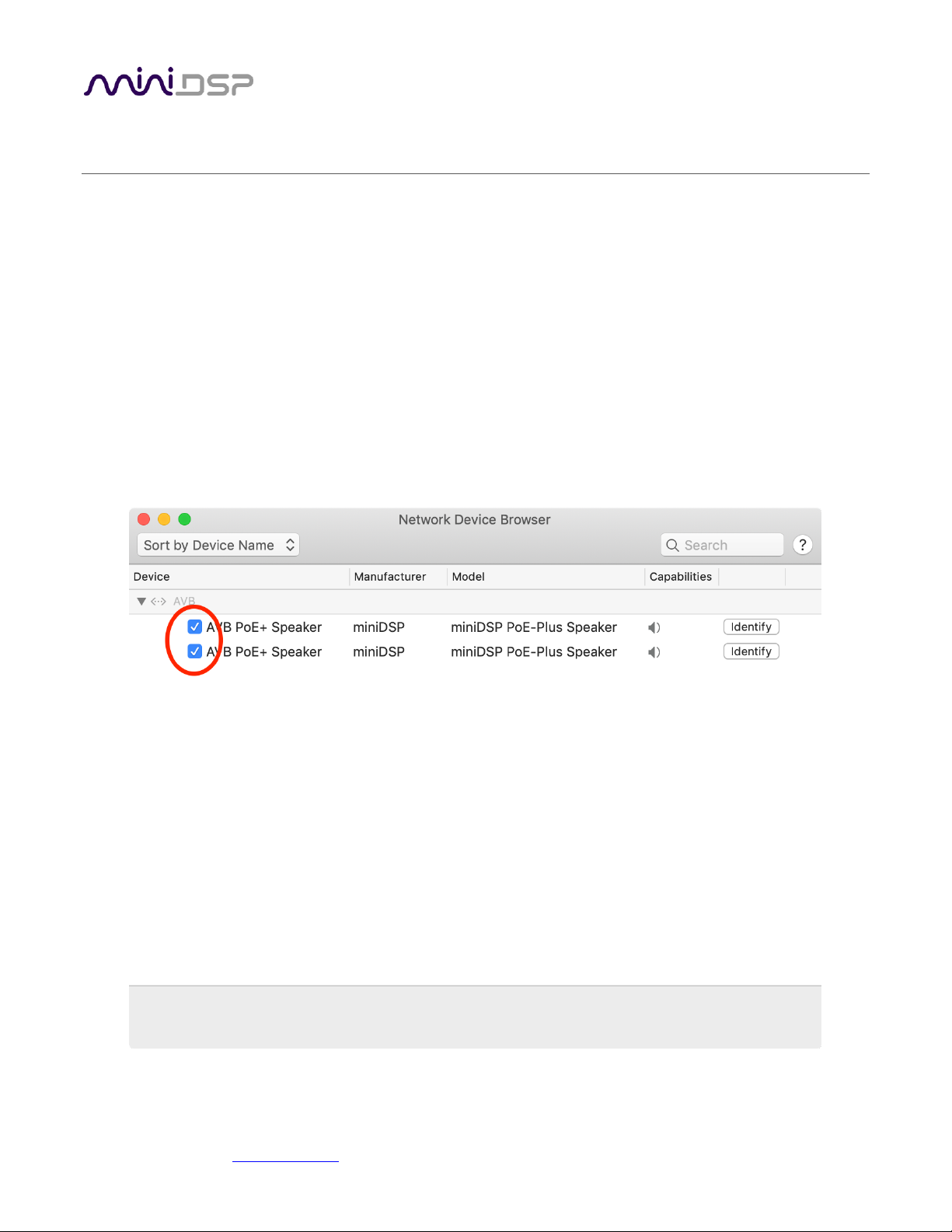
1. Open the program Audio MIDI Setup (in Applications->Utilities).
2. Drop down the Window menu and select Network Device Browser.
3. In the Network Device Browser window, you will see one or more AVB devices. The miniDSP SPK-4P
identifies as "AVB PoE+ Speaker". Click the checkbox next a device to enable it. (Shown as the red circle
in the screenshot below).
miniDSP Ltd, Hong Kong / www.minidsp.com / Features and specifications subject to change without prior notice 11
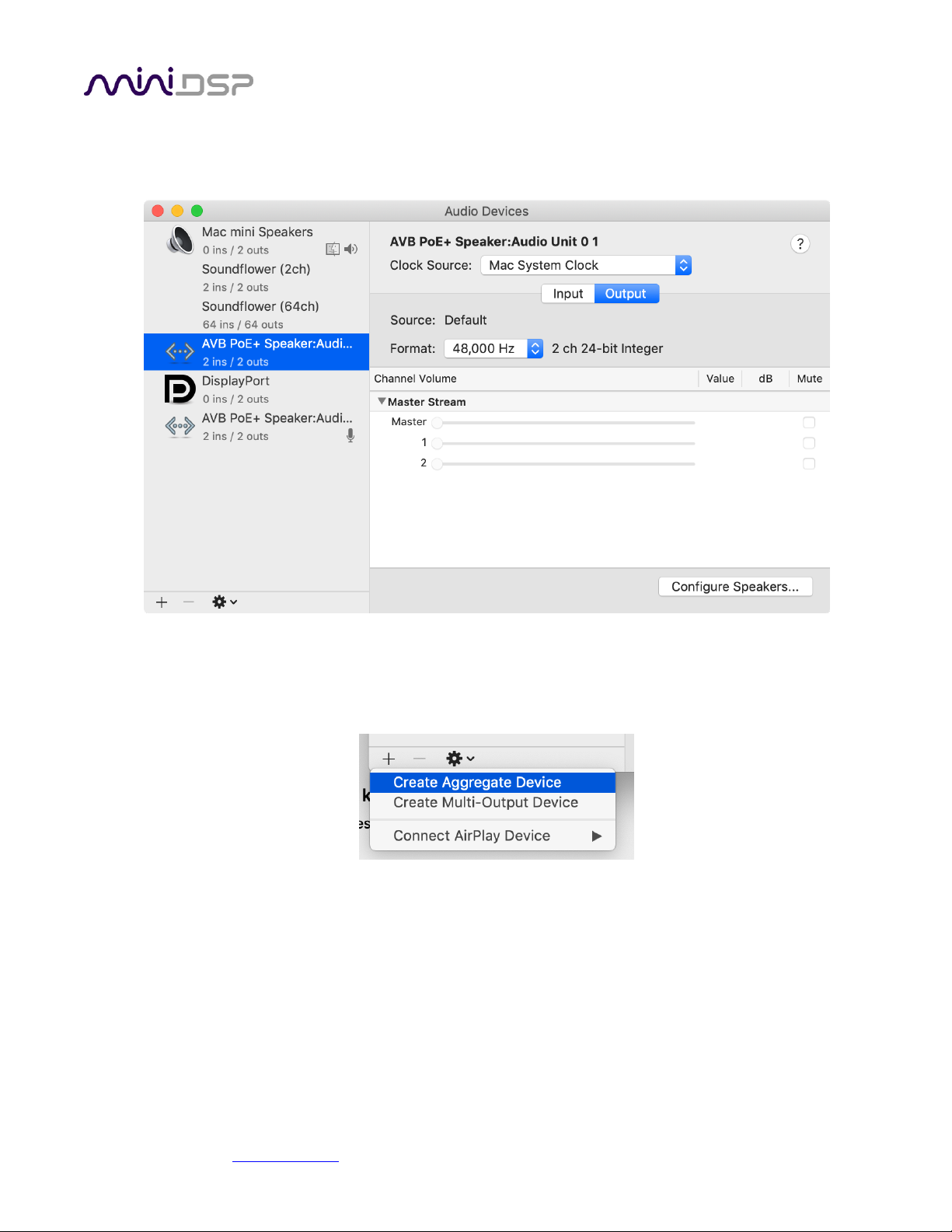
4. Drop down the Window menu and select Audio Devices. Enabled AVB devices will appear as audio
output devices in this window. Each miniDSP SPK-4P identifies as "AVB PoE+ Speaker". Select an SPK-4P
to confirm its output properties:
3.2 CONFIGURING MULTIPLE SPK-4P
1. Click on the “+” icon to create an aggregate device:

miniDSP Ltd, Hong Kong / www.minidsp.com / Features and specifications subject to change without prior notice 12
2. Select the SPK-4P to include in the aggregate device:

miniDSP Ltd, Hong Kong / www.minidsp.com / Features and specifications subject to change without prior notice 13
3. (Optional) Click on the Configure Speakers button and set the multichannel format to be used with the
aggregate device. Using the dropdowns, select the speaker and channel to be used for each virtual
speaker. Click Apply and then Done to exit.

miniDSP Ltd, Hong Kong / www.minidsp.com / Features and specifications subject to change without prior notice 14
4 SOFTWARE INSTALLATION
If you purchased your product directly from miniDSP, your software will be available from the User Downloads
section of the miniDSP website when your order ships. You will need to be logged into the website with the
account you created when purchasing to access the download.
If you purchased your product from a miniDSP dealer, you will receive a coupon together with the product.
Redeem this coupon and select the Plugin Group “MiniDSP 2x4 HD1” at the link below:
• https://www.minidsp.com/support/redeem-coupon
The User Downloads link is visible from the dropdown menu at the top right of the website page:
Navigate to the miniDSP Plug-ins section and download the zip file under the heading miniDSP 2x4 HD1. Unzip
the downloaded file by double-clicking.
Note: The Adobe Air framework may need a network connection the first time the plugin is used. If the plugin
does not start properly, see Troubleshooting.

miniDSP Ltd, Hong Kong / www.minidsp.com / Features and specifications subject to change without prior notice 15
4.1 MAC
4.2 POSSIBLE MAC INSTALLATION ISSUES
If double-clicking on an installer brings up a message that the installer cannot run, use this alternate method
(note that the name of the installer will be MiniDSP-2x4-HD.pkg, not MiniDSP_Plugin.pkg as shown in the
screenshots):
1. Right-click on the installer (or click while holding the Control key).
2. On the menu that pops up, move the mouse over the “Open With” item and then click on “Installer
(default).”
3. The following window will appear. Click on “Open.”
4.3 2X4 HD PLUGIN INSTALLATION
1. Navigate to the Plugins folder of the software download and then to the Mac folder.
2. The installer program is named MiniDSP-2x4-HD.pkg. To run it, double-click on it, or right-click and open as
described above. We recommend that you accept the default installation settings.
3. To run the MiniDSP-2x4-HD plugin, locate it in the Applications -> miniDSP folder and double-click on it. To
make it easier to run in future, right-click on its dock icon and select Options -> Keep in Dock.

miniDSP Ltd, Hong Kong / www.minidsp.com / Features and specifications subject to change without prior notice 16
5 CONFIGURING THE SPK-4P
The SPK-4P is configured with the miniDSP-2x4-HD plugin / user interface program. This screenshot shows the
user interface with the key areas highlighted:
5.1 SIGNAL FLOW AND PROCESSING OVERVIEW
The signal flow diagram of the SPK-4P is shown in the diagram below.
One of the three stereo input sources is selected by the user and passed to the input channel processing blocks.
These blocks include input gain, level metering, and parametric EQ.
The processed input channels are fed into a 2-in 4-out routing matrix. In the SPK-4P, input channels 1 and 2 are
usually routed directly to output channels 1 and 2.

miniDSP Ltd, Hong Kong / www.minidsp.com / Features and specifications subject to change without prior notice 17
The outputs from the routing matrix are processed through a comprehensive set of DSP functions – crossover
filters (high pass and low pass), parametric EQ, FIR filtering, and individual gain and delay adjustments. You can
configure these as needed according to your particular application. Finally, the output channels are converted to
analog and fed to the power amplifier inputs.
5.2 SYNCHRONIZING WITH THE SPK-4P
Click on the Search button:
All enabled, compatible AVB devices appear in the Device Tree:
Click on the speaker that you wish to connect the plugin to. The signal processing parameters in the user
interface will change to reflect the selected speaker. The “Connect” button will change as shown:
Note: the Connect button is not used as a button with the SPK-4P. It simply acts as a status indicator.
Once the plugin is connected to the SPK-4P, any changes subsequently made in the user interface will be
downloaded immediately to the SPK-4P. These changes are therefore audible in real time. This is referred to as
“online mode.”

miniDSP Ltd, Hong Kong / www.minidsp.com / Features and specifications subject to change without prior notice 18
5.3 KEY FEATURES
This section summarizes the key features of the plugin.
5.3.1 Master control
Once the plugin is online, the items in the Master Control area are active. The Mute button disables all audio
output:
The Master Volume display shows the current volume setting. The master volume can be set directly by clicking
here and typing a new value:
The IP Address and Auto fields are not used with the SPK-4P.
5.3.2 Configuration/preset selection
The set of data that controls the back-end processing is called a configuration. This includes crossovers,
parametric EQ, FIR filtering and the routing matrix. It does not include the master volume or mute status.
Four configurations are stored onboard. The currently selected preset is indicated by a dark background:
To switch to a different preset, just click on the desired button:
5.3.3 Saving and loading configurations
Configurations can be saved to and loaded from files. Each configuration is stored in a separate file. It is very
strongly recommended that each configuration programmed into the SPK-4P be saved to a file, to ensure that
the configuration is not lost if the SPK-4P is inadvertently reset.
To save the currently selected configuration to a file, drop down the File menu, then select Save and then Save
current configuration. In the file box, select a location and name of the file, and save it.

miniDSP Ltd, Hong Kong / www.minidsp.com / Features and specifications subject to change without prior notice 19
To load a configuration, ensure that the plugin is in online mode. Select the configuration preset that you wish
to load into. Then drop down the File menu, select Load, and then Load configuration to current slot.
To copy a configuration from one preset to another, save the configuration to a file, then select
a different configuration preset and load the file.
5.3.4 Restoring to defaults
Configurations can be reset to the factory defaults from the Restore menu. There are two options:
Factory Default
Reset all four configuration presets to the factory default settings.
Current Configuration Only
Reset only the currently selected configuration preset to the factory default settings.
5.3.5 Local configuration storage
When the Search box is used to connect to a SPK-4P, the previously used settings for that speakers are loaded
into the user interface. Note that these are not being loaded from the speaker but are stored locally in XML files
on the computer. The location of these files is:
/Users/[username]/Documents/MiniDSP/MiniDSP-2x4-HD/setting/[serialnumber]/
This is relevant in certain cases, such as if more than a different computer is being used to configure the SPK4P’s.
In this case, the best approach is to connect to the speaker, reset to defaults, then load the configurations for all
presets from saved files.
5.3.6 Input selection
When the plugin is connected to the SPK-4P, the currently selected input appears next to the “Inputs” label.
Click on the current input name to drop down a selector menu, from which you can select a different input. For
AVB audio, USB must be selected.

miniDSP Ltd, Hong Kong / www.minidsp.com / Features and specifications subject to change without prior notice 20
5.4 INPUT CHANNEL STRIPS
Channel label
Each input channel has a customizable label, which is shown at the top of the channel strip. This
label also appears on the routing matrix. To change the label, click on it, type a new label (up to
eight characters), and press the Return key.
Level meter, Current RMS level
Displays the current signal level in real time. (The plugin must be in online mode to display signal
levels.)
Gain adjustment
The gain of each channel can be adjusted by moving the Gain Adjustment slider, or by typing the
desired gain into the Current Gain text box. The maximum gain setting is 12 dB, and the
minimum gain setting is –72 dB. (0 dB, the default, is unity gain or no change in level.)
PEQ settings
Click on this button to open the parametric EQ settings window for that channel. There are ten
parametric EQ filters on each input channel. For more details, see Parametric EQ on page 23.
Mute
Press this button to mute that input channel. The button color and label changes to show that
the channel is muted.

miniDSP Ltd, Hong Kong / www.minidsp.com / Features and specifications subject to change without prior notice 21
5.5 ROUTING
The routing matrix is used to direct input channels (along the left) to output channels (along the top). To turn on
routing for a cross-point, click on that cross-point. The display will change from “Off” to show the mix level (0 dB
by default).
Below is the default routing matrix. The input and output channel names displayed on the matrix match those
set on the input and output control strips:
Changing the channel labels on the control strips changes them on the routing matrix, as an aid to ensuring
correct configuration. This is the typical routing that will be used with the SPK-4P:
At each cross-point, the gain of the signal being mixed can be adjusted to a value between -72 and +12 dB. To
adjust the gain, right-click on the cross-point and a gain control will appear. Adjust the gain with the slider, or by
typing in the value directly, then click close:

miniDSP Ltd, Hong Kong / www.minidsp.com / Features and specifications subject to change without prior notice 22
5.6 OUTPUT TAB
The Output tab displays a row of four output channel control strips. All output channels are identical.
5.6.1 Channel strip layout
Each output channel has a complete "strip" of controls.
5.6.2 Channel label
Each output channel has a customizable label, which is shown at the top of the channel strip. This label also
appears on the routing matrix. To change the label, click on it, type a new label (up to eight characters), and
press the Return key.
5.6.3 Level meter and gain control
Level meter, current RMS level
Displays the current signal level in real time. (The plugin must be in online mode to display signal
levels.)
Gain adjustment
The gain of each channel can be adjusted by moving the Gain Adjustment slider, or by typing the
desired gain into the Current Gain text box. The maximum gain setting is 12 dB, and the
minimum gain setting is –72 dB. (0 dB, the default, is unity gain or no change in level.)

miniDSP Ltd, Hong Kong / www.minidsp.com / Features and specifications subject to change without prior notice 23
5.6.4 Parametric EQ
Parametric equalization (PEQ) is a flexible type of equalization filter. It can be used to correct for errors in
loudspeaker output, to compensate for acoustic room effects, and to tailor the overall system response for best
sound. Click on the PEQ button to open the parametric equalizer settings window:
There are ten parametric EQ filters on each input and output channel. The window displays a frequency
response graph showing the combined response of all enabled parametric filters on that channel. For example,
the screenshot above shows a response curve created with a low-shelf boost filter at 100 Hz, a dip at 500 Hz,
and a high-shelf cut filter at 5000 Hz.
Hovering the mouse over the curve brings up an overlay showing the frequency and the gain at that frequency.
Each channel can be linked to one other channel. When a channel is linked to another, the PEQ settings of that
channel are mirrored to the other. Typically, the corresponding drivers on the left and right channels are linked:
left and right tweeter, left and right woofer, and so on. To link a channel, select the other channel from the
drop-down menu at the top left of the PEQ screen, and click the Link checkbox.

miniDSP Ltd, Hong Kong / www.minidsp.com / Features and specifications subject to change without prior notice 24
EQ band selection
Click on the tabs EQ1, EQ2, etc. to display the parameters for that filter.
Basic/Advanced
By default, each filter is in basic mode, and shows the controls described below. Advanced mode
enables custom biquad programming for almost infinite flexibility in filter implementation. This
is described in Custom biquad programming on page 29.
Filter type
Selects the type of filter:
PEAK Create a dip or a peak in the frequency response.
LOW_SHELF Reduce or increase part of the frequency spectrum below a given frequency.
HIGH_SHELF Reduce or increase part of the frequency spectrum above a given frequency.
ALL_PASS Create a phase shift across the frequency band. This can be useful for correcting
phase issues and for simulating analog crossovers.
Frequency
For the PEAK filter type, this is the center frequency of the peak or dip. For the HIGH_SHELF and
LOW_SHELF filter types, this is the frequency at which the gain is half of the set value. For the
ALL_PASS filter type, this is the center frequency of the phase shift.
Gain
For the PEAK filter type, this is the gain in dB at the center frequency. For the HIGH_SHELF and
LOW_SHELF filter types, this is the gain in dB reached at high or low frequencies respectively. A
filter has no effect if its gain is set to 0 dB. Gain can be adjusted in increments of 0.1 dB up to +/16 dB. This item is not present for the ALL_PASS filter type.
Q
Q controls the “sharpness” of the filter. For the PEAK filter type, lower Q gives a broader peak or
dip, while higher Q gives a narrower peak or dip. For the HIGH_SHELF and LOW_SHELF filter
types, Q controls how quickly the filter transitions from no gain to maximum gain. For the
ALL_PASS filter type, higher Q gives a steeper phase transition.
Bypass
The Bypass button enables or disables a filter. The filter is enabled if the button says “BYPASS”
and disabled if the button says “BYPASSED” (see screenshot below). Note that this button only
enables and bypasses a single filter; all other filters must be bypassed or enabled individually.

miniDSP Ltd, Hong Kong / www.minidsp.com / Features and specifications subject to change without prior notice 25
5.6.5 Crossover
Each output channel has independent high pass and low pass filters. Click on the Xover button to open the
crossover settings window:
Crossovers “split” the frequency band to send to different drivers. In a two-way loudspeaker, a low pass filter is
used to remove high frequencies from the signal sent to the woofer, and a high pass filter is used to remove low
frequencies from the signal sent to the tweeter. In a three-way speaker, the midrange driver will use both the
high pass and low pass filters. Crossover filters can also be used to limit low frequency content delivered to a
speaker or subwoofer, to help protect it from over-excursion.
Unlike conventional analog crossovers, the flexibility of DSP allows a completely arbitrary mix of different filter
slopes and types. Filters can be set at any frequency, or disabled completely. This allows maximum flexibility in
matching your crossover to the acoustic characteristics of the loudspeaker drivers.
The current channel is displayed in orange, with the others displayed in grey. Hovering the mouse over the curve
brings up an overlay showing the frequency and the attenuation at that frequency.

miniDSP Ltd, Hong Kong / www.minidsp.com / Features and specifications subject to change without prior notice 26
Basic/Advanced
By default, the crossover is in basic mode, and shows the controls described below. Advanced
mode enables custom biquad programming for almost infinite flexibility in crossover filter
implementation. This is described in Custom biquad programming on page 29.
Cutoff Frequency
Sets the nominal cutoff frequency of the crossover. In actual fact, the crossover has a more or
less gradual transition from “full on” to “full off,” as determined by the filter slope.
Filter type
Selects the type and slope of the filter. The steeper the slope, the more quickly frequencies
above or below the cutoff frequency are attenuated. There are three types of filter:
Butterworth (BW)
Available in 6, 12, 18, 24, 30, 36, 42, and 48 dB/octave, Butterworth crossover
filters are 3 dB down at the cutoff frequency.
Linkwitz-Riley (LR)
Available in 12, 24, 36, and 48 dB/octave, Linkwitz-Riley crossover filters are 6 dB
down at the cutoff frequency.
Bessel
Available in 12 dB/octave only, a Bessel filter gives a more gradual roll-off
through the crossover region.
Bypass
Clicking on the Bypass button disables or enables that high
pass or low pass filter. The filter is bypassed when the
button is "lit".
Each channel can be linked to one other channel. When a channel is linked to another, the crossover settings of
that channel are mirrored to the other. Typically, the corresponding drivers on the left and right channels are
linked: left and right tweeter, left and right woofer, and so on. To link a channel, select the other channel from
the drop-down menu at the top left of the Xover screen, and click the Link checkbox.
miniDSP Ltd, Hong Kong / www.minidsp.com / Features and specifications subject to change without prior notice 27
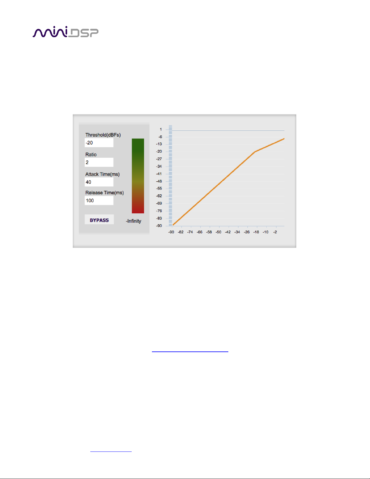
5.6.6 Compressor
The compressor reduces the gain of an output channel when the audio signal reaches a certain level as specified
by the Threshold parameter. The gain of the channel will be progressively reduced as the signal increases above
the threshold, according to the Ratio parameter. This can be used to limit the power delivered to speakers and
thus reduce the risk of damage from overdriving.
This screenshot shows an example Compressor setting:
(Note that the compressor algorithm is bypassed by default, so click on the Bypass button to see the curve as
shown here.)
In this example, the threshold is set to -20 dB, so the compressor will activate when the signal on that channel
reaches -20 dB (relative to full output). The ratio is set to 2, so if the input signal level to the compressor then
increases by 10 dB, the output level will increase by only 5 dB. If the input signal level to the compressor is at full
scale (0 dB), then the output level will be limited to -10 dB.
Two additional parameters control the action of the compressor: the attack time and the release time. These
two parameters govern how quickly the compressor activates when the signal level exceeds the threshold, and
how quickly it deactivates when the signal level reduces. The optimum settings may need to be tuned by ear. For
more information, see the Wikipedia article Dynamic range compression.

miniDSP Ltd, Hong Kong / www.minidsp.com / Features and specifications subject to change without prior notice 28
5.6.7 FIR
Each output channel has an FIR filter bank with a variable number of taps. Click on the FIR button to open the
FIR filter settings window:
FIR filtering is a powerful feature that allows very complex filters to be constructed (with the aid of suitable
design software). These filters can correct for amplitude only ("linear phase filters"), phase only, or a
combination or both. FIR filtering is described more in FIR filtering and design, starting on page 32.
5.6.8 Invert and mute
Each channel can be inverted in polarity, and individually muted. When either of these options is selected, the
visual indicator on the button is "lit":
5.6.9 Time delay
A delay of up to 80 ms can be applied to each output channel. To set the delay, click in the delay entry box for a
channel. The delay value can be entered numerically, and the up and down arrows can be used to change the
delay in small (0.01 ms) increments. The maximum time delay of 80 ms corresponds to a distance of
approximately 27.5 meters (about 90 feet).
The time delay corresponds to a distance. This distance is shown in centimeters below the entry box.

miniDSP Ltd, Hong Kong / www.minidsp.com / Features and specifications subject to change without prior notice 29
5.7 CUSTOM BIQUAD PROGRAMMING
Custom biquad programming is available in the PEQ and Crossover blocks. Its purpose is to allow you to directly
provide the low-level parameters aka biquad coefficients that control the digital filters of the SPK-4P, thus
providing an almost infinite degree of flexibility.
For example, you can create hybrid crossovers with staggered cutoff frequencies, create parametric EQ filters
beyond those provided in the easy-to-use “basic” interface, implement a Linkwitz transform, or mix crossover
and EQ biquads in the same block.
5.7.1 What’s a “biquad?
A biquad is the basic unit of processing that is used to create digital filters. It can be described either with an
equation or with a signal flow diagram, as shown here:
A single biquad like this can perform a great many functions, including all of the functions of a single parametric
EQ filter, one 6 or 12 dB/octave high pass or low pass filter, and more. Biquads are combined in series
(cascaded) to create more complex filters. The function that each biquad performs is determined by just five
numbers: a1, a2, b0, b1, and b2. These numbers are called the coefficients.
5.7.2 Using custom biquad programming
Each crossover block and PEQ filter has a selector that switches it to advanced mode:
In advanced mode, the biquad coefficients can be pasted directly into the user interface. These coefficients must
be calculated using a design program – see Biquad design software below for suggestions.

miniDSP Ltd, Hong Kong / www.minidsp.com / Features and specifications subject to change without prior notice 30
Parametric EQ advanced mode
In the parametric EQ blocks, advanced mode allows each individual filter to be specified by its
biquad coefficients. After pasting in the coefficients, click on the Process button for them to take
effect.
Parametric EQ file import (REW integration)
Multiple biquads in the parametric EQ block can be set at once by importing a coefficient file.
This file can be generated by Room EQ Wizard (REW) or by other programs. The design program
must be set for a 96 kHz sample rate. The number of filters is limited to a maximum of ten.
This example illustrates the correct file format:
biquad1,
b0=0.998191200483864,
b1=-1.9950521500467384,
b2=0.996920046761057,
a1=1.9950521500467384,
a2=-0.9951112472449212,
biquad2,
b0=0.999640139948623,
b1=-1.9981670485581222,
b2=0.9985489719847982,
a1=1.9981670485581222,
a2=-0.9981891119334211,
biquad3,
...
biquad4,
...
biquad10,
b0=1.0010192374642126,
b1=-1.9950555192569264,
b2=0.9940580112181501,
a1=1.995060938714333,
a2=-0.9950718292249559
Note that the last line must not have a comma at the end. If the file has less than ten biquads,
then only that number of biquads will be imported. For example, if importing a file with six
biquads, the first six filters will be set, and the last four will not be changed. (Note: if the last line
ends with a comma, that counts as an extra biquad.)
If the file contains more than ten biquads, then an error will be reported and no filters will be
changed.

miniDSP Ltd, Hong Kong / www.minidsp.com / Features and specifications subject to change without prior notice 31
Crossover advanced mode
The Crossover blocks have eight biquads for each output channel. In Advanced mode, all eight
biquads need to be specified. After pasting in the coefficients, click on the Process button for
them to take effect.
5.7.3 Biquad design software
Following are programs that can be used to design your biquad coefficients.
5.7.3.1 Biquad calculation spreadsheet
The community-developed biquad calculation spreadsheet allows many filter types to be calculated, including
notch filters, Linkwitz transforms, and filters with arbitrary Q-factor. Access this spreadsheet here (requires
Microsoft Excel):
• http://www.minidsp.com/images/fbfiles/files/All_digital_coefs_v1-20101026.zip
5.7.3.2 Room EQ Wizard (REW)
Room EQ Wizard is a free acoustic measurement and analysis tool, available for Windows, Mac and Linux
platforms. It includes the ability to automatically generate a bank of parametric EQ biquads based on a
measurement. These coefficients can be saved to a file from REW and loaded directly into a PEQ bank in a
miniDSP plugin. Room EQ Wizard can be downloaded here:
• http://www.roomeqwizard.com/#downloads
For guidance on using this feature, please refer to the app note Auto EQ with REW.

miniDSP Ltd, Hong Kong / www.minidsp.com / Features and specifications subject to change without prior notice 32
5.8 FIR FILTERING AND DESIGN
FIR filtering is a powerful and advanced feature of the SPK-4P. It allows construction of complex arbitrary
equalization and crossover filters with independent control of amplitude and phase. The parameters of each FIR
filter are set in the FIR settings window:
Browse Opens a file browser to select a file containing FIR filter coefficients. (See Filter file format
below).
Unload FIR Deletes the currently loaded filter from the display and from the DSP memory.
Send to DSP Writes the currently loaded filter into the DSP memory.
BYPASS Disables the FIR filter. The filter is disabled when the button is "lit."
File Mode / Manual Mode
In File Mode, the window displays the Browse and Unload FIR buttons as shown above. In
Manual Mode, the display changes to allow direct text entry of the FIR filter coefficients, as
shown below. The coefficients can be pasted into the window from a text editor.

miniDSP Ltd, Hong Kong / www.minidsp.com / Features and specifications subject to change without prior notice 33
5.8.1 FIR filtering overview
FIR ("finite impulse response") filtering differs from the IIR ("infinite impulse response") filters used in the PEQ
and crossover blocks. Technically speaking, IIR filters are recursive, meaning that each output value is partially
calculated from earlier output values as well as from input values. An FIR filter is specified by a large array of
numbers, whereas an IIR filter requires only a fairly small of values to be specified.
These numbers are conventionally referred to as "taps." The SPK-4P can compute a total of 4096 taps. These
taps can be distributed as you wish across the four output channels, with the limitation that each output
channel must have 6 or more taps and can have no more than 2048 taps. The decision on how many taps to
allocate to each channel up to you, and should be determined after working with an FIR filter design program
(see below). The number of taps is set in the lower right corner (click on the text entry box and type the desired
number of taps, then press Tab or Return):
5.8.2 FIR filter design software
The filter coefficients must be created with the aid of filter design software. miniDSP does not provide any such
software, instead referring you to the many software packages available for this purpose (both freeware and
commercial). Please see the FIR filter tools page on our website. The design program must be set for a 96 kHz
sample rate.
5.8.3 Filter file format
The filter coefficient file loaded in File Mode uses IEEE 754 single-precision binary floating-point format. The
number of entries in the file must not exceed the allocated number of taps.
In Manual Mode, the coefficients must be plain text in this format:
b0 = 1,
b1 = -1,
b2 = 0.5,
b3 = -0.5,
b4 = 0.2,
b5 = 1,

miniDSP Ltd, Hong Kong / www.minidsp.com / Features and specifications subject to change without prior notice 34
5.8.4 Loading filter coefficients
In File Mode:
4. Click Browse, navigate to the file containing the filter coefficients, and open it. A dialog will appear
confirming the number of coefficients loaded.
5. Confirm that the response curve is as you expect.
6. Press Send to DSP. This will write the coefficients into the DSP's memory.
7. To clear the filter coefficients, click Unload FIR and then Send to DSP.
In Manual Mode:
8. Cut and paste the coefficients from the text output of the design program.
9. Press the Process button.
10. Confirm that the frequency response graph is as you expect.
11. Press Send to DSP. This will write the coefficients into the DSP's memory.
12. To clear the filter coefficients, click Clear Taps and then Send to DSP.
If, after selecting a filter file or setting coefficients, the frequency response graph does not change as
expected, make sure that the Bypass button is turned off.
If you clear the filter taps, make sure that you also bypass the filter, otherwise there will be no audio
through that channel.
5.9 KEYBOARD SHORTCUTS
The miniDSP-2x4-HD plugin supports the use of the keyboard for many operations.
Tab
The Tab key moves the focus from the current user interface element to the next. A blue-grey
surrounding box usually indicates the user interface element with the focus. Shift-Tab moves the
focus in the opposite direction.
Up/down arrows
The up/down arrow keys (and in some cases, the left/right arrow keys) adjust the value of many
parameters, if they have the focus:
• Gain adjustment
• Crossover frequency and filter type
• PEQ filter frequency, gain, and Q
Space
The Space bar toggles buttons that have two states, such as Bypass, Invert, and Mute, if they
have the focus.

miniDSP Ltd, Hong Kong / www.minidsp.com / Features and specifications subject to change without prior notice 35
6 ADDITIONAL INFORMATION
6.1 SPECIFICATIONS
Network port
1 x auto speed sensing 10/100 Mbps RJ45 port
Network protocols &
IEEE standards
IEEE 802.3i/u for 10/100BaseT
IEEE 802.1AS, 802.1Qat, 802.1Qav for Audio Video Bridging standards
IEEE 1722.1 for discovery and enumeration
Power amplifier
Dual channel power amplifier for Master + Slave configuration.
2x15W RMS under +12V configuration
2x12W RMS under PoE+ mode (power carried over CAT5/6)
Audio sample rate /
Resolution
Input/output resolution: 24-bit integer
Sample rate: 96 kHz
Power supply
12 VDC single supply / 2.1 mm round plug / 45W
Dimensions (H x W x D)
125 x 125 x 131mm
Weight
1.3 kg
6.2 OBTAINING SUPPORT
1. Check the forums on miniDSP.com to see if this issue has already been raised and a solution or solutions
provided.
2. Contact miniDSP via the support portal at minidsp.desk.com with:
a. The product information including OS version and version of driver installed (for Windows).
b. A clear explanation of the symptoms you are seeing.
c. A description of the troubleshooting steps you performed and the results obtained.
 Loading...