

miniDSP Ltd, Hong Kong / www.minidsp.com / Features and specifications subject to change without prior notice 1
DDRC-88D
8-CHANNEL AUDIO PROCESSOR
WITH DIRAC LIVE® TECHNOLOGY
AND OPTIONAL UPGRADE FOR BASS MANAGEMENT AND CROSSOVER
Digital I/O version
User Manual

miniDSP Ltd, Hong Kong / www.minidsp.com / Features and specifications subject to change without prior notice 2
Revision history
Revision
Description
Date
0.1
First draft
31 July 2017
1.0
Public release
4 Sept 2017

miniDSP Ltd, Hong Kong / www.minidsp.com / Features and specifications subject to change without prior notice 3
TABLE OF CONTENTS
Important Information ...................................................................................................................................5
1 Product Overview ....................................................................................................................................7
1.1 Typical system configurations .................................................................................................................................... 7
1.2 How Dirac Live® works ............................................................................................................................................... 8
1.3 Configuration steps (basic mode) .............................................................................................................................. 9
1.4 Configuration steps (enhanced/bass management mode) ...................................................................................... 10
2 Hardware Connectivity ........................................................................................................................... 11
2.1 Digital input and output ........................................................................................................................................... 11
2.2 DC Power .................................................................................................................................................................. 12
2.3 USB ........................................................................................................................................................................... 12
3 Software Installation .............................................................................................................................. 13
3.1 Dirac Live license activation ..................................................................................................................................... 13
3.2 Installation ― Windows ........................................................................................................................................... 14
3.2.1 Possible Windows installation issues .............................................................................................................. 14
3.2.2 DDRC-88BM plugin installation ....................................................................................................................... 14
3.2.3 Dirac Live Calibration Tool (DLCT) installation ................................................................................................. 14
3.3 Installation ― Mac ................................................................................................................................................... 15
3.3.1 Possible Mac installation issues ....................................................................................................................... 15
3.3.2 DDRC-88BM plugin installation ....................................................................................................................... 15
3.3.3 Dirac Live Calibration Tool (DLCT) installation ................................................................................................. 15
4 The DDRC-88BM Plugin .......................................................................................................................... 16
4.1 Plugin user interface – basic mode .......................................................................................................................... 16
4.2 Synchronizing with the DDRC-88D ........................................................................................................................... 17
4.3 Master control .......................................................................................................................................................... 17
4.4 Configuration/filter set selection ............................................................................................................................. 17
4.5 Dirac Live information .............................................................................................................................................. 18
5 Acoustic Measurement for Dirac Live ...................................................................................................... 19
5.1 Loudspeaker and microphone positioning ............................................................................................................... 19
5.2 Preparing for acoustic measurement ....................................................................................................................... 20
5.2.1 Connections and microphone placement ....................................................................................................... 20
5.2.2 Subwoofer settings .......................................................................................................................................... 20
5.3 Configuring for measurement .................................................................................................................................. 21
5.3.1 Select the configuration/preset (enhanced/bass management mode) .......................................................... 22
5.3.2 Sound System tab ............................................................................................................................................ 22
5.3.3 Mic Config tab.................................................................................................................................................. 23
5.3.4 Output & Levels tab ......................................................................................................................................... 24
5.3.5 Custom System configuration ......................................................................................................................... 25
5.4 Running the measurements ..................................................................................................................................... 26
5.4.1 Listening environment ..................................................................................................................................... 27
5.4.2 Executing measurements ................................................................................................................................ 28
5.4.3 Completing the measurements ....................................................................................................................... 29
5.4.4 Viewing and redoing measurements ............................................................................................................... 29
5.5 Saving and loading projects ...................................................................................................................................... 29
6 Dirac Live Filter Design ........................................................................................................................... 30

miniDSP Ltd, Hong Kong / www.minidsp.com / Features and specifications subject to change without prior notice 4
6.1 Working with graphs ................................................................................................................................................ 31
6.2 Designing your target curve ..................................................................................................................................... 33
6.2.1 The Auto Target ............................................................................................................................................... 33
6.2.2 Editing the target curve ................................................................................................................................... 33
6.2.3 Guidelines for target curve design .................................................................................................................. 34
6.2.4 Saving and loading target curves ..................................................................................................................... 35
6.3 Generating correction filters .................................................................................................................................... 36
6.4 Loading filter sets ..................................................................................................................................................... 37
7 Using the DDRC-88D Audio Processor ..................................................................................................... 38
7.1 Configuring source equipment ................................................................................................................................. 38
7.2 Front panel ............................................................................................................................................................... 38
7.2.1 Status indicators .............................................................................................................................................. 38
7.2.2 Front panel controls ........................................................................................................................................ 38
7.3 Infrared remote control ........................................................................................................................................... 39
8 Enhanced/Bass Management Mode ....................................................................................................... 40
8.1 Plugin user interface – enhanced/bass management mode .................................................................................... 40
8.2 Signal flow ................................................................................................................................................................ 41
8.3 Plugin design/configuration guide ........................................................................................................................... 42
8.4 Connecting and configurations ................................................................................................................................ 43
8.4.1 Connection options ......................................................................................................................................... 43
8.4.2 More about configurations .............................................................................................................................. 44
8.4.3 Selecting a configuration ................................................................................................................................. 44
8.4.4 Saving and loading configurations ................................................................................................................... 44
8.4.5 Relationship with Dirac Live ............................................................................................................................ 45
8.4.6 Restoring to defaults ....................................................................................................................................... 45
8.5 Signal processing tabs .............................................................................................................................................. 46
8.6 LFE Mgt ..................................................................................................................................................................... 46
8.7 Routing ..................................................................................................................................................................... 48
8.8 Mixer ........................................................................................................................................................................ 49
8.9 Outputs..................................................................................................................................................................... 50
8.9.1 Channel label ................................................................................................................................................... 50
8.9.2 Gain control and level monitoring ................................................................................................................... 50
8.9.3 Parametric EQ .................................................................................................................................................. 51
8.9.4 Crossover settings ........................................................................................................................................... 53
8.9.5 Time delay ....................................................................................................................................................... 54
8.9.6 Invert and mute ............................................................................................................................................... 54
9 Additional Information ........................................................................................................................... 55
9.1 Specifications ........................................................................................................................................................... 55
9.2 MCU Firmware update ............................................................................................................................................. 56
9.2.1 Windows .......................................................................................................................................................... 56
9.2.2 Mac OS X .......................................................................................................................................................... 58
9.3 Activating enhanced/bass management mode........................................................................................................ 60
9.4 Troubleshooting ....................................................................................................................................................... 61
9.5 Obtaining support .................................................................................................................................................... 62

miniDSP Ltd, Hong Kong / www.minidsp.com / Features and specifications subject to change without prior notice 5
IMPORTANT INFORMATION
Please read the following information before use. In case of any questions, please contact miniDSP via the
support portal at minidsp.desk.com.
SYSTEM REQUIREMENTS
To configure your DDRC-88D audio processor, you will require a Windows or Apple Mac computer with the
following minimum specification:
Windows
• Intel Pentium III or later, AMD Athlon XP or later
• 2 Gigabytes (GB) of RAM or higher
• Keyboard and mouse or compatible pointing device
• Microsoft• ® Windows® Vista® SP1/Win7/Win8/Win10
• Two free USB 2.0 ports
Mac OS X
• Intel-based Mac with 1 GHz or higher processor clock speed
• 2 Gigabytes (GB) of RAM or higher
• Keyboard and mouse or compatible pointing device
• OS X 10.9 (Mavericks) to macOS 10.12 (Sierra)
• Two free USB 2.0 ports
DISCLAIMER/WARNING
miniDSP cannot be held responsible for any damage that may result from the improper use or incorrect
configuration of this product. Please read this manual carefully to ensure that you fully understand how to
operate and use this product, as incorrect use or use beyond the parameters and ways recommended in this
manual have the potential to cause damage to your audio system.
Please also note that many of the questions we receive at the technical support department are already
answered in this User Manual and in the online application notes on the miniDSP.com website. So please take
the time to carefully read this user manual and the online technical documentation. And if an issue arises with
your unit, please read through the Troubleshooting section first. Thank you for your understanding!
WARRANTY TERMS
miniDSP Ltd warrants this product to be free from defects in materials and workmanship for a period of one
year from the invoice date. Our warranty does not cover failure of the product due to incorrect connection or
installation, improper or undocumented use, unauthorized servicing, modification or alteration of the unit in any
way, or any usage outside of that recommended in this manual. If in doubt, contact miniDSP prior to use.

miniDSP Ltd, Hong Kong / www.minidsp.com / Features and specifications subject to change without prior notice 6
FCC CLASS B STATEMENT
This device complies with Part 15 of the FCC Rules. Operation is subject to the following two conditions:
• This device may not cause harmful interference.
• This device must accept any interference received, including interference that may cause undesired
operation.
Warning: This equipment has been tested and found to comply with the limits for a Class B digital device,
pursuant to Part 15 of the FCC Rules. These limits are designed to provide reasonable protection. This
equipment generates, uses and can radiate radio frequency energy and, if not installed and used in accordance
with the instructions, may cause interference to radio communications. However, there is no guarantee that
interference will not occur in a particular installation. If this equipment does cause harmful interference to radio
or television reception, which can be determined by turning the equipment off and on, the user is encouraged to
try to correct the interference by one or more of the following measures:
• Reorient or relocate the receiving antenna.
• Increase the separation between the equipment and receiver.
• Connect the equipment into an outlet on a circuit different from that to which the receiver is connected.
• Consult the dealer or an experienced radio/TV technician for help.
Notice: Shielded interface cable must be used in order to comply with emission limits.
Notice: Changes or modification not expressly approved by the party responsible for compliance could void the
user’s authority to operate the equipment.
CE MARK STATEMENT
The DDRC-88D has passed the test performed according to European Standard EN 55022 Class B.
A NOTE ON THIS MANUAL
This User Manual is designed for reading in both print and on the computer. If printing the manual, please print
double-sided. The embedded page size is 8 ½” x 11”. Printing on A4 paper will result in a slightly reduced size.
For reading on the computer, we have included hyperlinked cross-references throughout the manual. In
addition, a table of contents is embedded in the PDF file. Displaying this table of contents will make navigation
easier.
miniDSP Ltd, Hong Kong / www.minidsp.com / Features and specifications subject to change without prior notice 7
1 PRODUCT OVERVIEW
Thank you for purchasing a miniDSP DDRC-88D audio processor powered by Dirac Live®, the world’s premier
room correction solution. We are delighted to offer you this software and hardware combination, the fruit of
extensive research and development and years of experience in sound system tuning.
The DDRC-88D is an 8-channel digital audio signal processor (DSP) running the Dirac Live® room correction
algorithm. The onboard floating-point SHARC processor provides time and frequency correction of 8 channels
with optional bass management and active crossover configurations. Inputs and outputs are digital (AES/EBU x
4), provided on a DB-25 connector. All output channels are sample-rate-converted to the same rate as the input
(channels 1 and 2) to preserve system sample rate integrity.
The DDRC-88D is a member of the miniDSP Dirac Series of audio processors. Deploying a DDRC-88D will:
• Improve imaging and immersion
• Improve clarity of music and dialog
• Reduce listening fatigue
• Remove resonances and room modes
1.1 TYPICAL SYSTEM CONFIGURATIONS
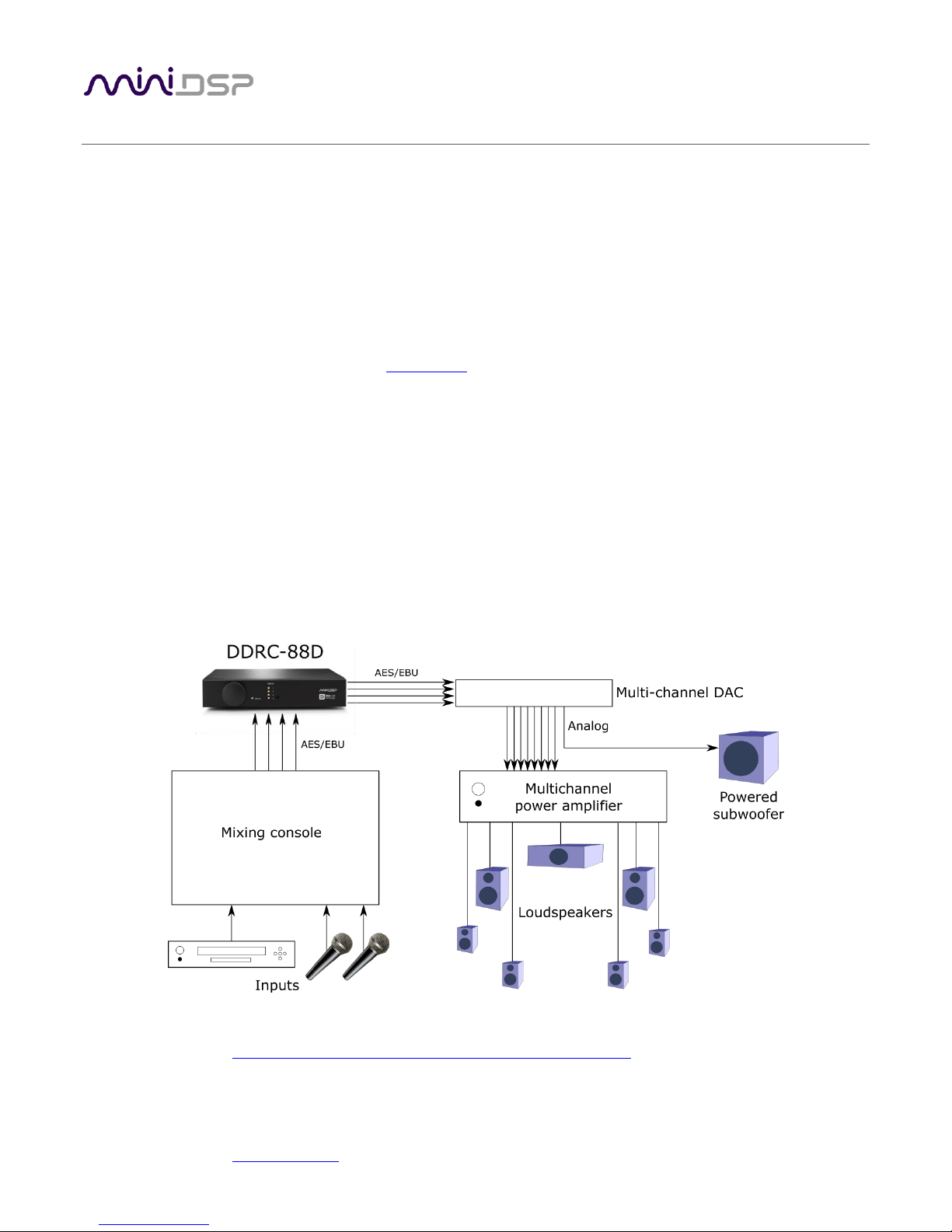
In studio or sound reinforcement applications, the DDRC-88D is typically connected between a mixing console
and a multichannel DAC, as shown below. Each channel can be set for either full-range or subwoofer operation,
and active multi-way systems can also be implemented.
The DDRC-88D can also be used for multi-room/multi-zone correction with a stereo source. See the application
note on our website, Multi-zone DRC with the DDRC-88D Dirac Live® processor.
miniDSP Ltd, Hong Kong / www.minidsp.com / Features and specifications subject to change without prior notice 8
Computer connectivity is used to perform acoustic measurements and generate digital room correction filters.
Up to four sets of correction filters can be stored on the DDRC-88D processor and recalled from the front panel
or via an infrared remote. Once the processor is fully configured, the computer is no longer needed.
1.2 HOW DIRAC LIVE® WORKS
The miniDSP DDRC-88D audio processor includes Dirac Live®, a premium mixed-phase room correction
technology. This technology is used not only in home stereo and home theater systems but also in cinemas,
recording studios, and luxury cars.
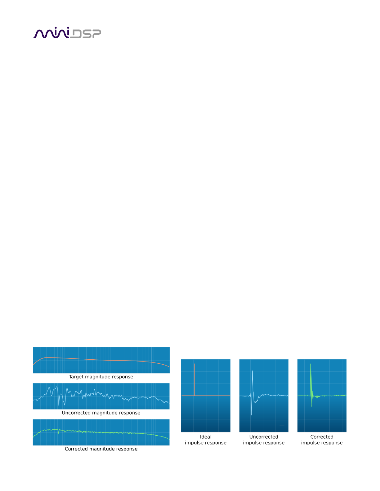
As with any room correction system, Dirac Live® corrects the system’s magnitude response (often referred to
imprecisely as “frequency response”). In contrast to fully automated systems, Dirac Live® corrects the
magnitude response towards a user-adjustable target response. The target response takes account of the
natural frequency range of the loudspeaker system and the normal effects of loudspeaker dispersion on the
measured in-room magnitude response.
In addition, Dirac Live® corrects the system’s impulse response, which reflects how the system responds to a
sharp transient such as a drumbeat. Reflections, diffraction, resonances, misaligned drivers, and so on, all
combine to smear out the transient. An ideal loudspeaker has none of these, so correcting the impulse response
makes the speaker in the room behave much more like that ideal loudspeaker. The impulse response is a critical
factor for accurate sound-staging, clarity and bass reproduction. Dirac Live® employs a sophisticated analysis
algorithm to make the optimal correction across the whole listening area, not just at a single point.
Dirac Live® accomplishes this using mixed-phase filters – filters that match a desired magnitude response and
generate a customized impulse response. This contrasts with the minimum-phase and linear-phase filters that
are commonly used in audio applications. While minimum-phase and linear-phase filters are relatively easy to
design, they are tightly constrained in their impulse response characteristics – neither can make a desired
change to the magnitude response independently of controlling the impulse response. In some cases, they may
even make things worse.
Mixed-phase filters are more difficult to design, but the audible performance of Dirac Live® is due to its success
in using mixed-phase filters to make the system response across the whole listening area more closely resemble
that of an ideal speaker. The energy from the direct wave and from early reflections is optimally combined to
arrive as a single wave front to the listener. Late reflections are left largely untouched, being corrected only for
their spectral coloration, as they contribute to a larger, more enveloping soundstage.
Illustration of Dirac Live® magnitude and impulse response correction

miniDSP Ltd, Hong Kong / www.minidsp.com / Features and specifications subject to change without prior notice 9
1.3 CONFIGURATION STEPS (BASIC MODE)
The steps for configuring the DDRC-88D audio processor with Dirac Live® are summarized as follows:
1. Connect the DDRC-88D audio processor into your system and install
software. See Section 2, Hardware Connectivity and Section 3,
Software Installation.
2. Run a series of acoustic measurements using the Dirac Live
Calibration Tool for miniDSP program, to capture the acoustic
behavior of your speakers and room. See Section 5, Acoustic
Measurement for Dirac Live.
3. Generate digital room correction filters that will be executed by the
DDRC-88D processor. Up to four filter sets can be downloaded into
the processor for easy real-time recall and auditioning. See Section
6, Dirac Live Filter Design.
4. Once the digital room correction filters are designed and
downloaded, the computer can be disconnected for normal
listening. See Section 7, Using the DDRC-88D Audio Processor.
miniDSP Ltd, Hong Kong / www.minidsp.com / Features and specifications subject to change without prior notice 10
1.4 CONFIGURATION STEPS (ENHANCED/BASS MANAGEMENT MODE)
The steps for configuring the DDRC-88D audio processor with Dirac Live® and the optional enhanced/bass
management mode upgrade are summarized as follows:
1. Connect the DDRC-88D audio processor into your system and install
software. See Section 2, Hardware Connectivity and Section 3,
Software Installation.
2. Configure output channel processing with the DDRC-88BM plugin.
This sets up individual control of each output channel in order to
implement (for example) active crossovers or multisub
management. See Section 8, Enhanced/Bass Management Mode.
3. Run a series of acoustic measurements using the Dirac Live
Calibration Tool for miniDSP program, to capture the acoustic
behavior of your speakers and room. See Section 5, Acoustic
Measurement for Dirac Live.
4. Generate digital room correction filters that will be executed by the
DDRC-88D processor. Up to four filter sets can be downloaded into
the processor for easy real-time recall and auditioning. See Section
6, Dirac Live Filter Design.
5. Configure bass management in the DDRC-88BM plugin (if
required). See Section 8, Enhanced/Bass Management Mode.
6. The computer can be disconnected for normal listening. See Section 7, Using the DDRC-88D Audio
Processor.
miniDSP Ltd, Hong Kong / www.minidsp.com / Features and specifications subject to change without prior notice 11
2 HARDWARE CONNECTIVITY
All connections to the DDRC-88D are made on the rear panel.
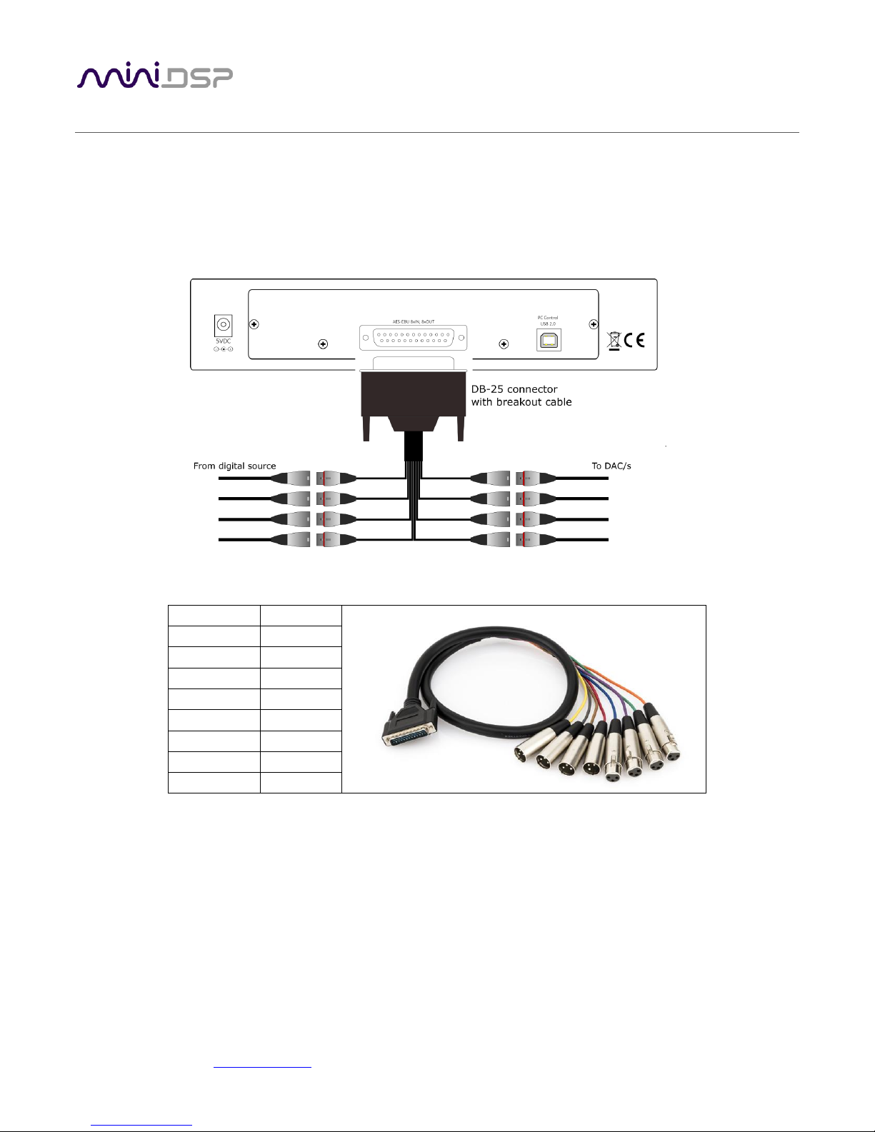
2.1 DIGITAL INPUT AND OUTPUT
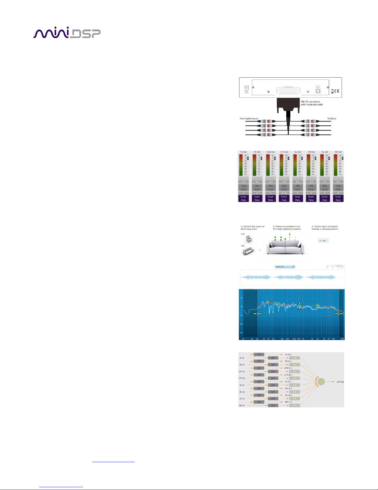
Up to eight channels can be connected to the DDRC-88D via the supplied DB-25 breakout cable. 4 AES/EBU
digital inputs and four AES/EBU digital outputs are present on the connector using the TASCAM pinout.
The supplied cable has the following channel assignment:
Channels
Color
In 1&2
Purple
In 3&4
Blue
In 5&6
Green
In 7&8
Orange
Out 1&2
Yellow
Out 3&4
Red
Out 5&6
Grey
Out 7&8
Brown
Input sample rate
All inputs have asynchronous sample rate conversion (ASRC) and accept sample rates from 32 to
192 kHz. Each pair of channels can have a difference sample rate.
Output sample rate
All outputs run at the sample rate of input channels 1 and 2. If there is no signal on input
channels 1 and 2, all output channels run at 48 kHz.
Note that the internal sample rate is 48 kHz regardless. An asynchronous sample rate conversion on the output
channels is used to produce data at the sample rate detected on input channels 1 and 2, thus preserving the
sample rate integrity of the system as a whole.
miniDSP Ltd, Hong Kong / www.minidsp.com / Features and specifications subject to change without prior notice 12
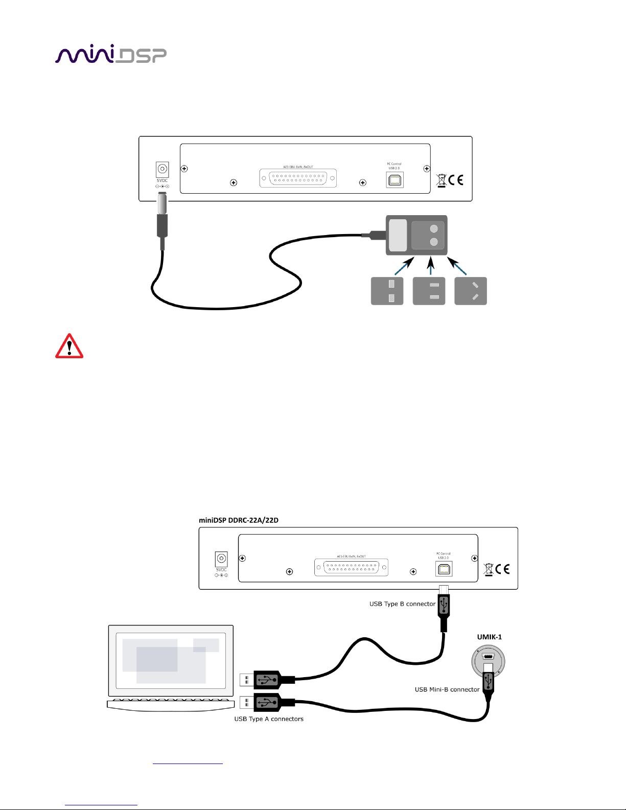
2.2 DC POWER
The supplied 5 VDC power supply includes a set of interchangeable power pins. Fit the correct pins for your
country. Connect the DC plug to the 5 VDC power socket.
Apply power to the DDRC-88D only after all input and output connections have been made. The DDRC88D uses little power and can be left powered on all the time.
2.3 USB
To configure the DDRC-88D using Dirac Live Calibration Tool for miniDSP:
• Connect the USB port of the DDRC-88D to a USB 2.0 port on your computer using the supplied cable.
• Connect a miniDSP UMIK-1 to a second USB port on your computer.
Note: the miniDSP UMIK-1 is the only measurement microphone that can be used with the DDRC-88D and Dirac
Live Calibration Tool for miniDSP. Other USB microphones or microphones connected to external soundcards
cannot be used.
miniDSP Ltd, Hong Kong / www.minidsp.com / Features and specifications subject to change without prior notice 13
3 SOFTWARE INSTALLATION
If you purchased your product directly from miniDSP, your software will be available from the User Downloads
section of the miniDSP website when your order ships. You will need to be logged into the website with the
account you created when purchasing to access the download.
If you purchased your product from a miniDSP dealer, you will receive a coupon together with the product.
Redeem this coupon and select the Plugin Group “Dirac Series” at the link below:
• https://www.minidsp.com/support/redeem-coupon
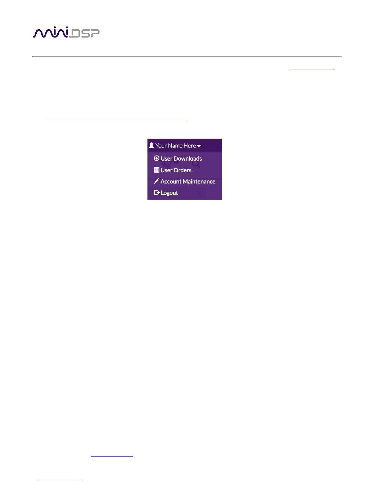
The User Downloads link is visible from the dropdown menu at the top right of the website page:
Navigate to the Dirac Series section and then to DDRC-88BM Software. There you will find a single download
containing all software. Download this file and unzip it on your computer (on Windows, right-click and select
“Extract All...”; on Mac, double-click). The folder containing the software has a name like DDRC-88-BM_v1_4
and will contain the following folders:
Dirac Live
This folder contains the installers for Dirac Live Calibration Tool for miniDSP (DLCT)
multichannel version, which is used to perform the Dirac Live calibration, including taking
measurements, generating correction filters, and loading them into the DDRC-88D. There are
separate Windows and Mac versions.
Plugins
This folder contains the installers for the DDRC-88BM plugin, used to set up non-Dirac signal
processing, configure remote control codes and perform various other maintenance operations
on the DDRC-88D. There are separate Windows and Mac versions.
firmware
This folder contains the firmware for the DDRC-88D. miniDSP may occasionally provide updated
firmware to improve functionality and performance – see Section 9.2 MCU Firmware update for
the upgrade procedure.
3.1 DIRAC LIVE LICENSE ACTIVATION
As of version 1.2.0 of Dirac Live Calibration Tool, license activation is done automatically when DLCT recognizes a
valid Dirac Live license code in the hardware unit itself. No separate manual activation step is required.
miniDSP Ltd, Hong Kong / www.minidsp.com / Features and specifications subject to change without prior notice 14
3.2 INSTALLATION ― WINDOWS
3.2.1 Possible Windows installation issues
The miniDSP software requires that a number of other frameworks be installed for it to work. For Windows 7
and later, these packages should be installed automatically. For earlier versions of Windows, please download
and install the following frameworks before attempting to install any miniDSP software. You can also manually
install these if you receive an error message that required software is missing.
• Microsoft .NET framework (version 3.5 or later)
• Latest version of Adobe Air
• Microsoft Visual C++ 2010 Redistributable Package: for x86 (32-bit operating system) or x64 (64-bit operating
system).
3.2.2 DDRC-88BM plugin installation
1. Navigate to the Plugins folder of the software download and then to the Windows folder.
2. Double-click on the DDRC_88_BM_v1_4.exe installer program to run it (the version number v1_4 may be
different). We recommend that you accept the default installation settings.
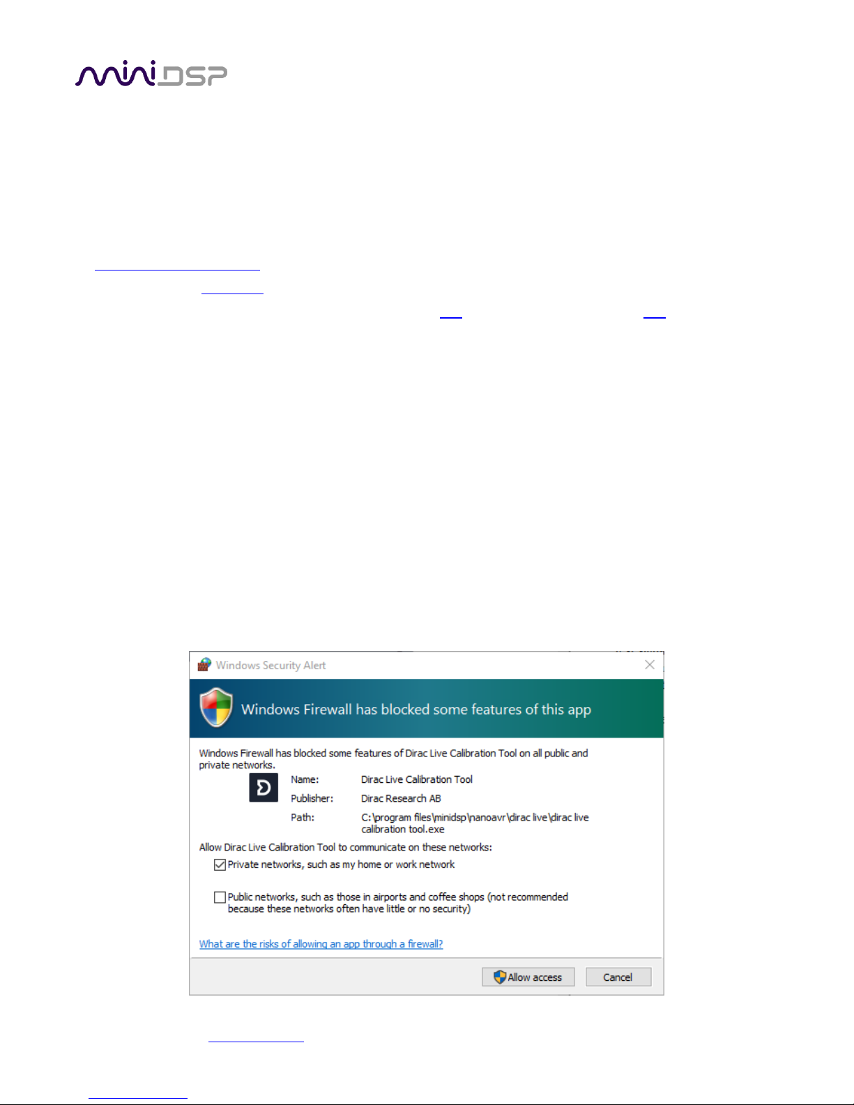
3.2.3 Dirac Live Calibration Tool (DLCT) installation
1. Navigate to the Dirac Live folder of the software download and then to the Windows folder.
2. Double-click on the installer to run it. The installer will have a name similar to Dirac Live Calibration Tool (8
channels) v1.2.0.8354 Setup.exe (the version number starting with v1.2... may be different). We
recommend that you accept the default installation settings.
The first time you run DLCT, you may see a warning from Windows Firewall as shown below. If so, ensure that
“Private networks...” is checked and “Public networks...” is not checked. Then click on “Allow access.”
miniDSP Ltd, Hong Kong / www.minidsp.com / Features and specifications subject to change without prior notice 15
3.3 INSTALLATION ― MAC
3.3.1 Possible Mac installation issues
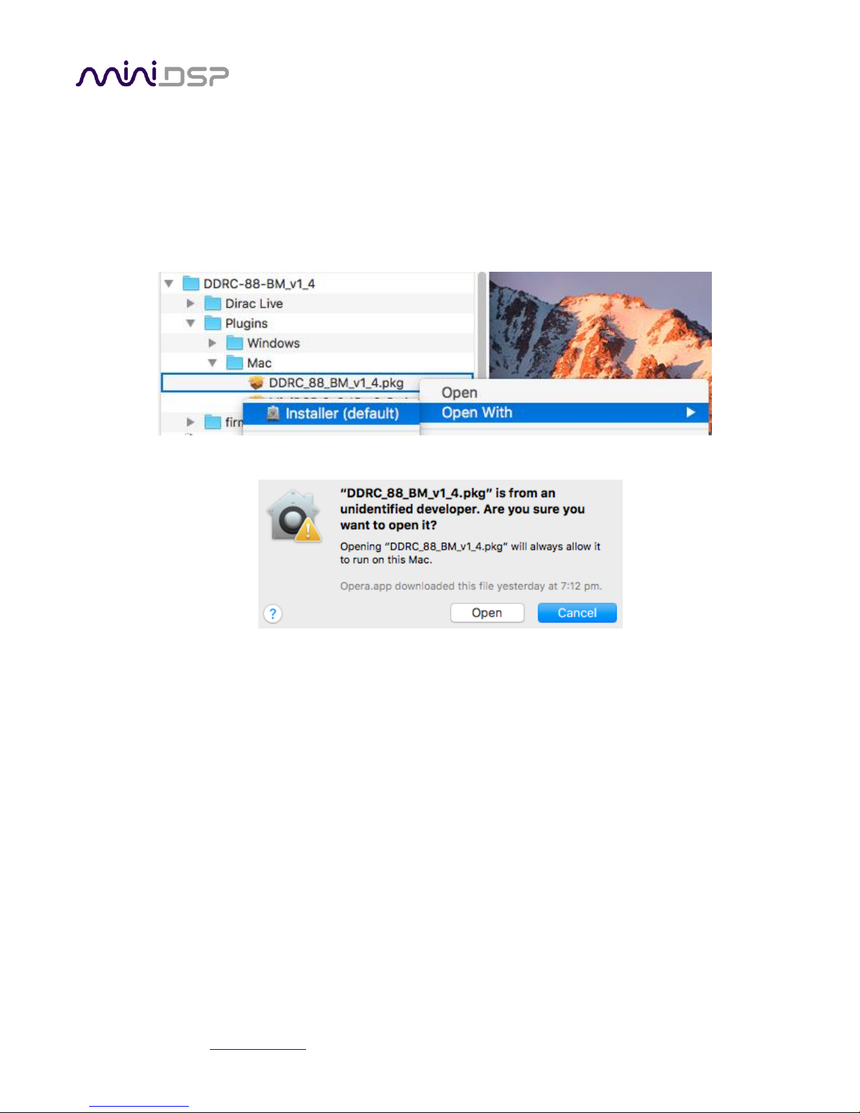
If double-clicking on an installer brings up a message that the installer cannot run, use this alternate method:
1. Right-click on the installer (or click while holding the Control key).
2. On the menu that pops up, move the mouse over the “Open With” item and then click on “Installer
(default).”
3. The following window will appear. Click on “Open.”
3.3.2 DDRC-88BM plugin installation
1. Navigate to the Plugins folder of the software download and then to the Mac folder.
2. The installer program is named DDRC_88_BM_v1_4.pkg (the version number v1_4 may be different). To
run it, double-click on it, or right-click and open as described above. We recommend that you accept the
default installation settings.
3. To run the DDRC-88BM plugin, locate DDRC-88-BM.app in the Applications -> miniDSP folder and double-
click on it. To make it easier to run in future, right-click on its dock icon and select Options -> Keep in Dock.
3.3.3 Dirac Live Calibration Tool (DLCT) installation
1. Navigate to the Dirac Live folder of the software download and then to the Mac folder.
2. The installer program will have a name similar to Dirac Live Calibration Tool (8 channels) v1.2.0.8392.mpkg
(the version number starting with v1.2... may be different). To run it, double-click on it, or right-click and
open as described above. We recommend that you accept the default installation settings.
3. To run DLCT, locate Dirac Live Calibration Tool.app in the Applications -> miniDSP -> nanoAVR folder and
double-click on it. To make it easier to run in future, right-click on its dock icon and select Options -> Keep
in Dock.
miniDSP Ltd, Hong Kong / www.minidsp.com / Features and specifications subject to change without prior notice 16
4 THE DDRC-88BM PLUGIN
The DDRC-88BM plugin is the software program that interfaces with the DDRC-88D for all control functions
except for Dirac Live calibration. It can operate in two modes:
• Basic mode. Dirac Live is enabled but the optional bass management and crossover functionality is not.
• Enhanced/bass management mode. Dirac Live is enabled as well as bass management and crossover
functionality. See Section 8, Enhanced/Bass Management Mode for further information on this functionality.
If you purchased a DDRC-88D in basic mode and later upgrade to enhanced/bass management mode, you will
need to perform the upgrade procedure described on page 60.
Be sure to quit Dirac Live Calibration Tool for miniDSP before starting the DDRC-88BM plugin.
Running both programs at the same time may result in communication conflicts and odd behavior.
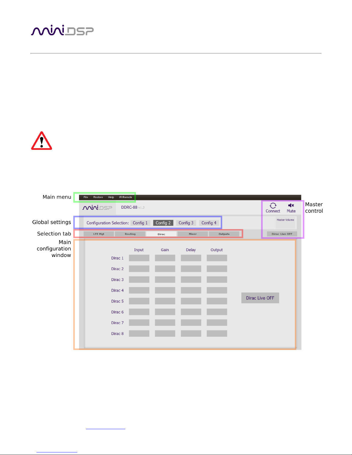
4.1 PLUGIN USER INTERFACE – BASIC MODE
Upon starting the plugin, the main user interface appears. The screenshot below shows the user interface with
the key areas highlighted.
At the top of the screen are a set of menus and buttons, which are described on following pages. Below that, on
the Dirac tab, is a display of the Dirac Live parameters. This tab is active in both basic and enhanced/bass
management modes.
The four other tabs (“LFE Mgt,” “Routing,” etc.) are not active in basic mode. They can be viewed when the
plugin is offline (see next page) in order to provide you with a preview of the enhanced/bass management
functionality.
miniDSP Ltd, Hong Kong / www.minidsp.com / Features and specifications subject to change without prior notice 17
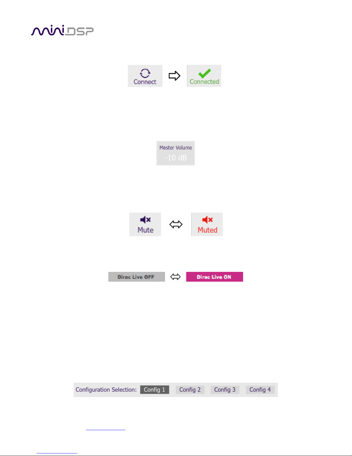
4.2 SYNCHRONIZING WITH THE DDRC-88D
Connect the DDRC-88D to a USB 2.0 port on your computer. Then click on the Connect button:
If you are running the plugin in enhanced/bass management mode, a dialog box with additional connection
options may appear. See page 43.
If successful, the button will change to a green tick as shown above. For the sake of brevity, this state is referred
to as “online” whereas the earlier state with the circular arrows is referred to as “offline.” In addition, the
Master Volume field will display the current volume setting:
4.3 MASTER CONTROL
These controls are only effective when the plugin is online.
The Mute button disables all audio output:
The Dirac Live button turns Dirac Live filtering on and off. (A Dirac Live correction filter must have been loaded
into the currently selected configuration for this to work.)
4.4 CONFIGURATION/FILTER SET SELECTION
Once correction filters have been loaded into the DDRC-88D, the four configuration selection buttons can be
used to select between them.
If the plugin is operating in enhanced/bass management mode, these buttons also select the processing data for
the four other tabs (“LFE Mgt,” “Routing,” etc.). Because these different configurations contain data that has
already been loaded into the flash memory of the hardware unit, they are also often referred to as “presets.”
Configuration/preset selection can also be done with the front panel encoder or an infrared remote control –
see Section 7, Using the DDRC-88D Audio Processor.
By default, configuration 1 is selected:
miniDSP Ltd, Hong Kong / www.minidsp.com / Features and specifications subject to change without prior notice 18
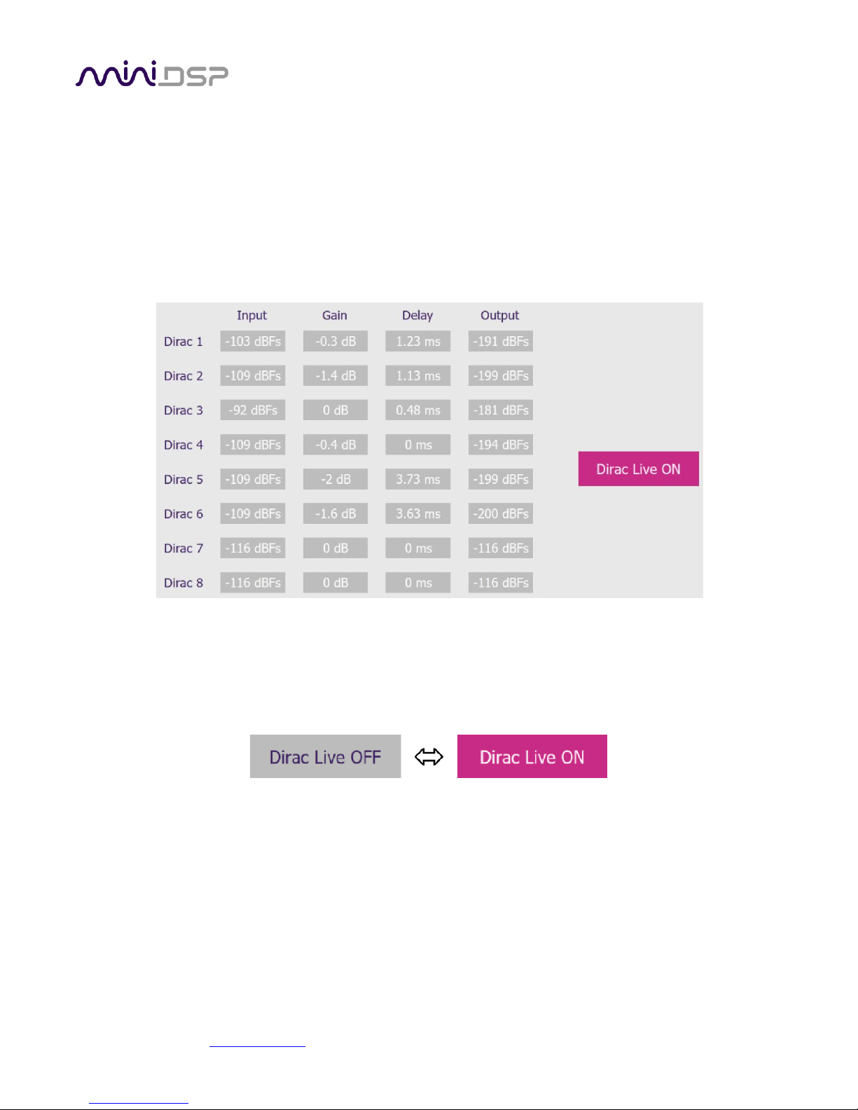
4.5 DIRAC LIVE INFORMATION
In basic mode, the only active tab in the interface is Dirac. Note that Dirac Live calibration is performed with the
separate program Dirac Live Calibration Tool for miniDSP (DLCT), as described in Sections 5 and 6. Once
calibration has been performed, you can quit DLCT and run the plugin to view Dirac Live delay and gain settings
and real-time levels.
In the DDRC-88BM plugin, this tab displays the gains and delays of the Dirac Live filters loaded into the DDRC88D. (The plugin must be online to display them.) These gains and delays were calculated by DLCT during its
Optimize phase and cannot be changed by the user – they are “read only.” Here is an example:
Note that the displayed gains and delays are applied even when Dirac Live filtering is turned off.
The Input and Output columns display the current signal level at the inputs and outputs of the Dirac Live
processing block.
The button is used to turn Dirac Live processing on and off.

miniDSP Ltd, Hong Kong / www.minidsp.com / Features and specifications subject to change without prior notice 19
5 ACOUSTIC MEASUREMENT FOR DIRAC LIVE
The Dirac Live Calibration Tool For miniDSP uses a set of measurements made in your listening room to gather
all the acoustical information about your room and speakers that it needs to calculate the correction filters.
If you have purchased the enhanced/bass management mode upgrade and intend to configure individual output
channels with crossovers or filters, you must do that before running a Dirac Live Calibration. See Section 8,
Enhanced/Bass Management Mode.
5.1 LOUDSPEAKER AND MICROPHONE POSITIONING
Prior to performing acoustic measurements, loudspeaker and subwoofer positioning should be optimized. In
particular, the location of the subwoofer will have a large impact on bass response. With Dirac Live®, you have
more freedom with loudspeaker and subwoofer placement, but the best result will still be achieved if optimal
placement is used together with Dirac Live®.
Typical home theater measurement setup
A total of nine measurements are needed, with the microphone located in different positions in the room and
pointed vertically (that is, at the floor or ceiling). The first measurement must be taken at the central location of
the listening area, as this location sets the levels and delays of each speaker. While this location will usually be
an equal distance from both speakers, Dirac Live® will adjust in cases where it is not. Eight more measurements
are then taken at locations spread around the listening area and at different heights from the floor.

miniDSP Ltd, Hong Kong / www.minidsp.com / Features and specifications subject to change without prior notice 20
5.2 PREPARING FOR ACOUSTIC MEASUREMENT
5.2.1 Connections and microphone placement
The figure below shows a typical connection diagram for performing acoustic measurement. No changes to the
audio connections are needed. Simply:
• Connect the supplied USB (type A to type B) cable from the DDRC-88D to a USB port on the computer.
• Connect a USB cable (type A to mini type B) from the UMIK-1 to a USB port on the computer.
Place the UMIK-1 microphone into a microphone stand and position the computer and cabling so that there is
enough freedom of movement to move the microphone into the needed locations. A small tripod stand is
supplied with the UMIK-1, but a larger stand with boom arm can be used if desired. If necessary a longer USB
cable can be used (up to a total USB cable length of 5 meters). In larger spaces, an active USB repeater may be
needed. We recommend that the microphone be oriented vertically (pointed at the floor or ceiling) and the “90
degree” calibration file used (see Mic Config tab on page 23).
5.2.2 Subwoofer settings
We recommend that during calibration the low pass filter of the subwoofer be disabled if possible, or set to its
highest frequency if it cannot be disabled. Any EQ on the subwoofer should be disabled or set “flat.” High pass
filters used to protect the driver from over-excursion should be left in place.
If the subwoofer’s low pass filter is an important part of the overall bass management in the system, it can be
re-enabled after completing Dirac Live calibration and loading correction filters into the DDRC-88D.

miniDSP Ltd, Hong Kong / www.minidsp.com / Features and specifications subject to change without prior notice 21
5.3 CONFIGURING FOR MEASUREMENT
Start Dirac Live Calibration Tool for miniDSP (DLCT).
Be sure to quit the DDRC-88BM plugin before starting Dirac Live Calibration Tool for miniDSP.
Running the two programs at the same time will result in communication conflicts and odd behavior.
Logo and status progress bar
This area shows a progress bar with current status when the program is performing calculations. If the
program seems unresponsive at any time, check the status here.
Screen selection tabs
Each tab selects a different step of the calibration process. These are generally worked through in order,
from top to bottom. This section covers the first four tabs; the final two are covered in Dirac Live Filter
Design.
Load and save a project
A set of measurements can be saved to a file and reloaded at a later time. See Saving and loading projects.
Back / Next
Use these two buttons to advance to the next tab when each is complete, or to go back to the previous
tab to make alterations. The tabs at the left can also be clicked on directly.
Help open/close
Click on the small Help divider at the right of the screen to open a pane with help on the currently
selected tab. Click on the divider again to close the help pane.

miniDSP Ltd, Hong Kong / www.minidsp.com / Features and specifications subject to change without prior notice 22
5.3.1 Select the configuration/preset (enhanced/bass management mode)
If you are running the plugin in enhanced/bass management mode and have changed the settings on the Mixer
or Outputs tabs away from the defaults, then you must ensure that you have selected the correct
configuration/preset prior to running measurements for Dirac Live calibration.
If you are running the plugin in basic mode, or have not made changes to the Mixer or Outputs tabs, then it
does not matter which configuration/preset is selected.
5.3.2 Sound System tab
On the Sound System tab, set the following parameters.
Choose system configuration
Use the dropdown menu to select your system configuration.
For multi-channel surround-sound, use 5.1 Speaker System or 7.1 Speaker System if it is desired
that Dirac Live calibrate for a 10 dB “LFE alignment gain” to the subwoofer channel. If the
calibration for LFE alignment gain is not required or if a different speaker configuration is
required, use Custom System. (See Custom System configuration on page 25 for further
information.)
Test signal playback device
Preset to DDRC-88. This will ensure that test signals are sent into your audio system via the
DDRC-88D processor.
If the entry for DDRC-88 is not showing, check that your DDRC-88D processor is connected via
USB and powered on, click the Rescan button, and then use the drop-down menu to select
DDRC-88. If that still doesn’t work, see Section 9.4, Troubleshooting.
Once you have verified that this tab is correct, click the Proceed button.

miniDSP Ltd, Hong Kong / www.minidsp.com / Features and specifications subject to change without prior notice 23
5.3.3 Mic Config tab
On the Mic Config tab, set the following parameters.
Recording device
Preset to the UMIK-1.
If the UMIK-1 is not showing, ensure that the
UMIK-1 is connected securely to the computer via
USB, then go back to the Sound System tab and
click on Rescan. Then use the drop-down menu to
select the UMIK-1.
Recording channel
Select 1 from the drop-down menu.
Microphone calibration file
Each UMIK-1 measurement microphone is individually calibrated to ensure accuracy. To
download the unique calibration file for your microphone, go to the UMIK-1 page and enter your
microphone's serial number. It is in the form xxx-yyyy and labelled on the microphone. Ensure
that you download both the regular calibration file and the “90-degree” calibration file. (The
latter is generated specifically for use with miniDSP’s multi-channel Dirac Live® processors such
as the DDRC-88D and the nanoAVR DL.)
Then click on the Load File button and select your calibration file.
For surround sound applications, it is best to use the 90-degree calibration file as this
is created specifically for the vertical microphone orientation. This file is downloaded
with the suffix “_90deg” in the file name.
Once you have verified that this tab is correct, click the Proceed button.

miniDSP Ltd, Hong Kong / www.minidsp.com / Features and specifications subject to change without prior notice 24
5.3.4 Output & Levels tab
The Output & Levels tab is used to set the signal levels used in the subsequent measurements. We recommend
following this procedure:
1. Set the Output volume slider all the way down, at -80 dB.
2. Click on the Test button for the left channel and gradually increase Output volume. You should hear pink
noise playing from the left speaker. Continue to increase volume until it is at a moderate level, such that
your voice would have to be raised to converse with someone sitting next to you.
3. Set the Input gain slider so that the blue bar on the level meter is about in the middle of the green section,
or around -12 dB:
4. Click again on the Test button for the left channel to stop the test signal.
5. Click on the Test button for each of the remaining channels. If any channel is not in the green zone, use the
Channel volume sliders to adjust the relative volume of the channels. (Some readjustment of Input gain
and Output volume may also be needed.)
Note: if large adjustments are required to the Channel volume sliders, you may have an issue with gain structure
in downstream electronics, and gain levels in e.g. amplifiers should be adjusted for a more uniform set of
readings.
When done, click the Proceed button.

miniDSP Ltd, Hong Kong / www.minidsp.com / Features and specifications subject to change without prior notice 25
5.3.5 Custom System configuration
On the Sound System tab, choose the Custom System configuration if any of the following apply:
• The system does not fit any of the three predefined configurations (Stereo, 5.1, 7.1).
• You want to use a different channel mapping than the default.
• You do not want the DDRC-88D to calibrate for a 10 dB LFE alignment gain on the subwoofer channel.
After choosing Custom System, you will need to
select the number of channels that you want to use.
When you get to the Output & Levels tab, it will show controls for the number of channels that you selected:
Channel name
Type any name you like for each channel.
Output channel
By default, each input channel maps to the same numbered output channel (input channel 1 to
output channel 1, and so on). The dropdown selectors can be used to change this mapping. Note
that DLCT will not let you assign more than one output channel to each input channel.
If your custom system configuration has less than eight channels, inputs and outputs are
assigned in sequential order. For example, for a 4.1 channel system, connect to inputs and
outputs 1 through 5.
Subwoofer
The subwoofer checkbox tells the Dirac Live analysis algorithm to use a different method to
detect the impulse on that channel, which in turn affects the delay that will be assigned to that
channel. This is needed because of the limited frequency response of the subwoofer.
Reminder: in Custom System configuration, the DDRC-88D does not calibrate for a 10 dB LFE alignment gain on
the subwoofer channel. If this gain is required it can be added after calibration if, for example, the subwoofer
has a 10 dB LFE gain switch.

miniDSP Ltd, Hong Kong / www.minidsp.com / Features and specifications subject to change without prior notice 26
5.4 RUNNING THE MEASUREMENTS
Acoustic measurements are performed on the Measurements tab.
Measurements should always be performed under good conditions. While the measurement technique used by
Dirac Live is quite robust, low-frequency noise (traffic, machinery, aircraft, storms) in particular can adversely
affect measurement accuracy. A high level of ambient noise can degrade signal to noise ratio and prevent the
algorithm from analyzing the test sweep signal properly. Minimize the effect of any external noise, ensure that
measurement signal levels are adequate, and/or choose a suitable time for performing measurements.

miniDSP Ltd, Hong Kong / www.minidsp.com / Features and specifications subject to change without prior notice 27
5.4.1 Listening environment
The Measurements tab presents three different listening environments as a visual guide to positioning the
microphone for each of the nine measurements: Chair, for a single listening seat; Sofa, for multiple listening
seats; and Auditorium, for a large dedicated home theater or larger venue with staggered seating. Use the icons
at the left of the screen to select the listening environment.
The center of the screen contains a pictorial representation of the selected listening environment, with dots
marking the recommended microphone locations. Completed measurements are shown in green, while the next
measurement to be done is highlighted in yellow and has a red arrow marker pointing to it. A drop-down menu
underneath selects three different views, which should be used to help you place the microphone in a suitable
location.
While the visual guide indicates a suitable set of microphone locations, these locations can be varied to suit
individual circumstances. It is, however, imperative that the first measurement is taken in the center of the
listening area, as this measurement is used to set the levels and delays of each channel. The subsequent eight
measurements should be well spread out over the entire listening area so that Dirac Live can acquire a good set
of measurements that capture the acoustic behavior of the room. Placing all microphone locations too close to
each other may result in “over-correction” that will sound dry and dull.

miniDSP Ltd, Hong Kong / www.minidsp.com / Features and specifications subject to change without prior notice 28
For example, if using the Chair listening environment, spread the microphone positions over a circle with a
diameter of a meter (three feet). Vary the height of the microphone up and down by 30 cm (one foot) from the
initial position. If using the Sofa or Auditorium listening environment, again spread the measurement locations
over the full listening area and vary microphone height by a significant amount.
A different set of locations other than those indicated by the visual guide and the above guidelines can be used
if necessary. The important thing is to ensure that the measurement locations are spread out over the whole
listening area and that the microphone is moved a sufficient distance vertically as well as horizontally.
In some cases, such as when the listening area is very close to the loudspeakers or the loudspeakers have a very
narrow dispersion pattern, the size and in particular the height of the measurement area can be reduced, to
avoid discrepancies caused by varying output response from the speakers themselves.
5.4.2 Executing measurements
With the microphone in place at the central location and pointed vertically (that is, towards the ceiling or floor),
click on the Start button. The DDRC-88D will generate a test signal, audible as a frequency sweep through the
left speaker, then the right, and so on through all channels. Finally, the frequency sweep plays through the left
speaker again.
While the measurement proceeds, the time-domain response graph of the captured audio signal is displayed at
the bottom of the measurement tab. (This graph is related to the magnitude response but is not the same
display. Its purpose is to verify that the recorded signal level is in a suitable range.)
After completion of the measurement sweeps, the status bar will update with a progress indicator as the
program performs calculations on the measurement. If the measurement was successfully captured, the red
arrow marker will advance to the next location to be measured.
If the program indicates that the measurement was not successful, you will need to take corrective action. The
most common errors are related to signal level:
• The measurement signal is too low to ensure a clean capture.
• The measurement signal is too high and the audio signal has exceeded the maximum level (clipping). This is
shown in red on the signal graph.
In either case, go back to the Output & Levels tab and adjust Output volume, Input gain, or the Channel volume
slider for the channel that caused the problem. Then re-run the measurement. (You do not need to redo the
measurements you have already successfully completed.)

miniDSP Ltd, Hong Kong / www.minidsp.com / Features and specifications subject to change without prior notice 29
5.4.3 Completing the measurements
After each successful measurement, the location marker (red arrow) will advance to the next location. Move the
microphone to that location, using the three views (top, front, oblique) as a guide to positioning it. Then click on
Start again. Repeat this process until all nine locations have been successfully measured.
Note: it is good practice to save the project periodically while performing measurements (see Saving and loading
projects below).
5.4.4 Viewing and redoing measurements
Click on the green dot for any completed measurement to display its measured time-domain response graph.
After clicking on a green dot, a small red “X” will appear next it. Click on the “X” to delete the measurement. The
status bar will indicate that the program is recalculating parameters.
To redo a measurement, delete it, move the microphone to the appropriate location, and click on Start. Note: if
more than one measurement is deleted, the marker will move to the lowest-numbered one.
It is important that all nine measurements are completed in order to ensure best results from the
optimization algorithm. Being patient and thorough will pay audible dividends!
Once all nine measurements have been successfully completed, click the Proceed button.
5.5 SAVING AND LOADING PROJECTS
Each set of measurements and the associated configuration settings are called a project. The project should be
saved at regular intervals by clicking on the Save button. The default location for project files is
My Documents\MiniDSP\nanoAVR\Projects (Windows) or Documents/MiniDSP/nanoAVR/Projects (Mac).
A project can be reloaded at any time by clicking on the Load button. This enables you to generate new
correction filters for different target curves at a later date, or to redo any of the measurements. (Note: if you
wish to change between the Chair, Sofa, or Auditorium listening environments, you will need to start a new
project.)

miniDSP Ltd, Hong Kong / www.minidsp.com / Features and specifications subject to change without prior notice 30
6 DIRAC LIVE FILTER DESIGN
The Filter Design tab shows sets of graphs for the various channels. Click on the tabs at the right to display the
response graphs for different sets of channels (left and right, center, subwoofer, and surrounds, in the case of
5.1 and 7.1 systems). For each set of graphs, a number of variants can individually be turned on and off with the
checkboxes above the graphs.
Avg. spectrum (before)
The average of the measured magnitude responses. These plots are shown in light blue.
Avg. spectrum (after)
The predicted average magnitude response after correction. These plots are shown in green, and
can be viewed only after filters have been generated with the Optimize button.
Target
The target curve – that is, the desired in-room magnitude response. This curve is user-adjustable
so you can fine-tune it to best suit your speakers, room, and preferences. See Designing your
target curve on page 33.
All (before)
All of the measured magnitude responses. These plots are shown dark blue.
All (after)
All of the predicted magnitude responses after correction. These plots are shown in dark green,
and can be viewed only after filters have been generated with the Optimize button.

miniDSP Ltd, Hong Kong / www.minidsp.com / Features and specifications subject to change without prior notice 31
The graphs showing all nine measurements are useful for seeing how much variation there is across the listening
area:
To display the impulse response instead of the magnitude response, click on the Impulse button at the top left
of the display. All nine individual impulse responses can be shown as well as the average response. The
predicted responses after correction can be viewed after filters are generated with the Optimize button (see
Generating correction filters on page 36).
To return to the magnitude response, click on the Spectrum button.
6.1 WORKING WITH GRAPHS
Initially, the left and right front channels are shown. Some channels are linked together, as indicated by the
small “chain” icons on the tabs at the right of the graph. When channels are linked, their graphs display
together, and they share the same target curve. By default, the front left and right, surround left and right, and
rear left and right channels are linked.

miniDSP Ltd, Hong Kong / www.minidsp.com / Features and specifications subject to change without prior notice 32
To unlink a channel, click on its chain icon. It will then be unlinked from the other channels. To link it to another
channel or groups of channels, drag its tab on top of the channel or group of channels that you want it linked to.
Initially, you may wish to link all speaker channels together, as shown at right in the diagram
above, as this will make it easier to experiment with target curves. Once you are up and running
with target curves and filter sets, you can experiment with different target curves for different
channel groups.
The response graphs can be viewed at a larger scale. To zoom in and out:
• Drag-select a region of the graph to zoom in on it. (Click the left button, move the mouse while holding
the button, release the button.) You can then drag-select a region again to zoom in further.
• Double-click on the graph to zoom back out to the previous zoom level, or click on
the small “–” sign next to the zoom indicator at the top right of the display.
miniDSP Ltd, Hong Kong / www.minidsp.com / Features and specifications subject to change without prior notice 33
6.2 DESIGNING YOUR TARGET CURVE
The target curve is the desired in-room magnitude response with the DDRC-88D processor performing digital
room correction.
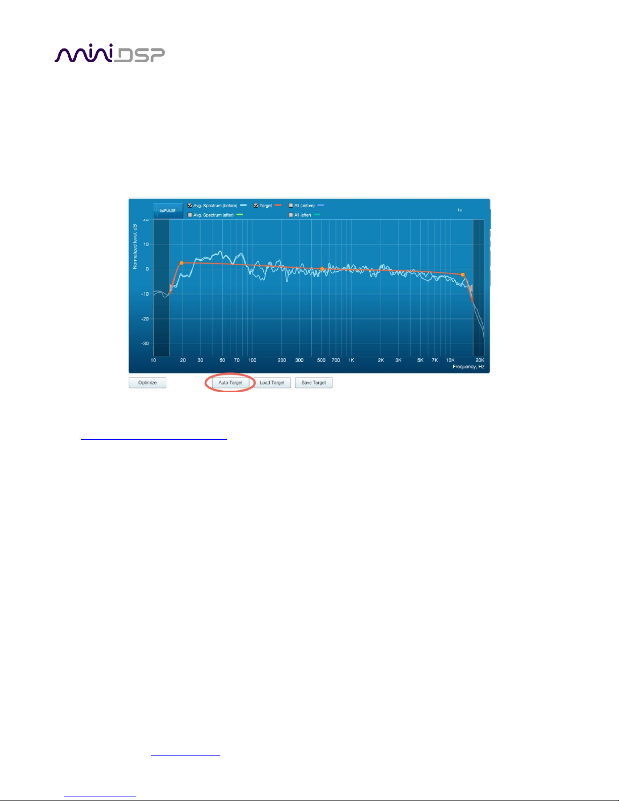
6.2.1 The Auto Target
When first viewing the Filter Design tab, an estimated target curve suitable for your speakers is shown as the
red curve. This calculated target curve can be restored at any time by clicking on the Auto Target button.
Note: restoring the auto target will erase the current target curve. If you wish to keep it, you can save it to a file
– see Saving and loading target curves on page 35.
6.2.2 Editing the target curve
You can edit the target curve to produce any desired magnitude response. This is done with the use of anchor
points, shown as orange dots on the curve:
• Drag an anchor point to move it.
• Double-click on the target curve to add an anchor point.
• Double-click on an anchor point to delete it.
The regions to the left and right of the response graphs that are shaded in a darker color are excluded from
magnitude response correction. You can adjust the frequency range for your system and preferences. For
example, low-frequency noise (traffic, machinery) may be present in some environments, so it is best to adjust
the frequency range to exclude these frequencies from the correction. Or, you may be happy with the in-room
response at higher frequencies, so you can set the frequency region to limit correction to the modal region (up
to 300 Hz, in a typical room).

miniDSP Ltd, Hong Kong / www.minidsp.com / Features and specifications subject to change without prior notice 34
To alter the region of correction, drag the grey handles on either side of the graph. Note that you can’t drag
these handles over an anchor point, so you may need to move or delete an anchor point that is “in the way.”
If channels are linked, the same target curve is used for that group of linked channels. To create a separate
target curve for a single channel, unlink it as described in Working with graphs.
6.2.3 Guidelines for target curve design
Care should be taken to create a target curve that works well with your speakers and room, as well as suiting
your personal preferences. Small changes to the target curve can have significant effects on the tonal quality of
the system, so it is important that you experiment with different target curves to find the optimum.
If you initially don’t achieve a satisfactory result, please ensure that you have spread your measurements over a
sufficiently large area and with sufficient variation in height. The following guidelines will help you understand
how to adjust your target curve.
Low-frequency extension and boost
All loudspeakers have a natural low-frequency roll off. Setting the target curve to boost the
region below the speaker’s natural roll off frequency may result in overdriving the speakers,
especially with smaller loudspeakers and depending on your listening habits. As a general rule, a
home theater system should use bass management to direct low frequency content to the
subwoofer.
The auto-target estimates the low-frequency roll-off and curve. You should determine by
listening whether this estimate is suitable for your system, and adjust the target curve
accordingly.

miniDSP Ltd, Hong Kong / www.minidsp.com / Features and specifications subject to change without prior notice 35
High-frequency “tilt”
The target curve is the desired measured response of loudspeakers in a room, in contrast to
measurements made of a loudspeaker during its design under anechoic (measured in free space)
conditions. While high-quality loudspeakers are usually designed for a flat on-axis anechoic
response, these same speakers when placed into a listening room will tend to have a downwardsloping or “tilting” response at high frequencies, due to the effects of limited dispersion at high
frequencies and greater acoustic absorption.
A completely flat in-room response is therefore usually not desirable and will tend to sound thin
or bright. Start with a target curve that follows the natural behavior of your speakers in your
room, and then experiment with greater or lesser degrees of tilt in the treble region to obtain
the most natural timbral balance.
Low-frequency adjustment
A completely flat response at low frequencies, with complete elimination of peaks due to room
modes, may sound light in the bass. Often, a slight increase in the target curve below 100 Hz will
give a more balanced sound, yet without introducing audible irregularities in bass response.
Magnitude response dips
In some cases, it may be helpful to adjust the target curve to follow dips in the magnitude
response. This can occur where, for example, the listening area is very close to the speakers and
the measurements exhibit a dip caused by the vertical response of the speakers themselves. In
such a case, adjusting the magnitude response to follow the dip will avoid making the speakers
sound worse elsewhere in the room. (You may also wish to try a different set of measurement
locations.)
Unlinking left and right channels
Usually, the corresponding left and right channels (front left and right, surround left and right,
and rear left and right) should remain linked for target curve adjustment, to ensure that both
sides produce the same response across the listening area. In certain unusual circumstances,
such as where the magnitude response dip discussed above shows up on only one side, you can
try unlinking channels and making separate adjustments.
6.2.4 Saving and loading target curves
To allow you to experiment with different target curves, you can save a target curve to a file and reload it at a
later time. Click on the Save Target button to save the target curve of the currently displayed channel or group
of channels.
To load a target curve, click on Load Target. The currently displayed channel or group of channels will have its
target curve updated. (Loading a target will erase the current target curve, so be sure to save it first if needed.)

miniDSP Ltd, Hong Kong / www.minidsp.com / Features and specifications subject to change without prior notice 36
6.3 GENERATING CORRECTION FILTERS
Once you have a target curve set to your satisfaction, click on the Optimize button.
The status bar will update as the algorithm progresses. The entire algorithm may take some time to complete,
depending on the speed of your computer. When the algorithm completes, the predicted average magnitude
response will be shown in green. (The predicted impulse response can be viewed by clicking on the Impulse
button.)
Dirac Live Calibration Tool for miniDSP will contact the Dirac license server to verify its license, so
you will need to be connected to the Internet to perform this step. If a firewall is in place, it must
allow HTTP (normal web traffic) to pass. Otherwise, an error such as the following may appear:
Once the filters are generated, click the Proceed button.

miniDSP Ltd, Hong Kong / www.minidsp.com / Features and specifications subject to change without prior notice 37
6.4 LOADING FILTER SETS
The Export tab initially shows four empty “slots” for filter sets (a filter set is one filter for every channel). Filter
sets are managed with a “drag and drop” metaphor:
• To load the most recently generated filter set into the processor, drag the box at the top left (in this example
labeled “HT 1 Jan 2016”) and drop it onto an empty slot (*).
• To remove a filter set, click on its name (oriented vertically), drag it from the slot and drop it on the trashcan
icon at the top right.
To load a filter set into a slot that already has filters loaded, first delete the loaded filter set by
dragging it onto the trashcan icon, then drag and drop the current filter set onto the now-empty slot.
The two main controls on this tab are:
Filter
Turn this on to enable the Dirac Live® correction filters.
Output volume
Move the slider to adjust the master volume of the processor. Output volume can also be
adjusted by the front panel control knob or an infrared remote control.
(*) If you are running the plugin in enhanced/bass management mode and have configured the Mixer and
Outputs tabs of the DDRC-88BM plugin away from the defaults, you must load the filters into the same slot as
the preset selected when running the measurements for Dirac Live calibration.

miniDSP Ltd, Hong Kong / www.minidsp.com / Features and specifications subject to change without prior notice 38
7 USING THE DDRC-88D AUDIO PROCESSOR
Once the desired correction filters have been downloaded into the DDRC-88D audio processor, the computer is
not required and can be disconnected.
7.1 CONFIGURING SOURCE EQUIPMENT
Dirac Live aligns the gain and delay of all channels. Any settings to this effect in the source equipment should
therefore be disabled.
7.2 FRONT PANEL
The front panel and/or an infrared remote can be used to control:
• Filter set selection
• Master volume
• Master mute (remote control only)
• Dirac Live® filtering enable/bypass (remote control only)
7.2.1 Status indicators
The current status of the DDRC-88D is indicated by a set of LEDs:
Dirac Live Dirac Live® filtering is enabled. This LED also blinks when the unit is muted.
Filter Set Indicates the currently selected filter set (1 through 4).
7.2.2 Front panel controls
The DDRC-88D audio processor uses a minimalist physical control design with a single control knob.
To change the volume
Rotate the control knob clockwise to increase the volume, and counter-clockwise to decrease it.
To change the selected filter set
Briefly press the control knob. The current Filter Set LED blinks quickly. Rotate the control knob
until the desired Filter Set LED is blinking. Press the control knob again, and the selected LED will
remain steady.

miniDSP Ltd, Hong Kong / www.minidsp.com / Features and specifications subject to change without prior notice 39
7.3 INFRARED REMOTE CONTROL
Many standard and programmable remote control units can
be used with the DDRC-88D. By default, the DDRC-88D
recognizes the Apple Remote, with the key assignments
shown at right.
(The commands Config Inc and Config Dec change the
selected configuration preset up or down. For example, if
the currently selected preset is 1, pressing Config Inc
changes it to 2. Note that switching between presets takes
several seconds.)
In addition, the DDRC-88D can “learn” the control codes of your current remote if it supports one of the
following remote control codes:
• NEC
• Sony
• Philips RC6
To initiate the learning process, run the DDRC-88BM plugin and click Connect. Drop down the IR Remote menu
and select IR learning. Click on the Learn button for an operation, and then press the desired button on the
remote control. If the code is accepted, a dialog will appear to show that the code was recognized the status will
change to show a tick.
If the processor does not recognize the remote control code, then it will time out and display a message saying
that IR learning failed.
Once programmed, check that the programmed buttons perform the expected function.
To "unlearn" a command, press the Learn button and wait for the plugin to time out.
To restore the default Apple remote commands, “unlearn” all commands.

miniDSP Ltd, Hong Kong / www.minidsp.com / Features and specifications subject to change without prior notice 40
8 ENHANCED/BASS MANAGEMENT MODE
In enhanced/bass management mode, the DDRC-88BM plugin has a powerful set of additional signal processing
functions. This section acts as a reference for these functions. While the following applications notes are written
for the DDRC-88A (analog I/O version), they also apply to the DDRC-88D:
• Implementing active speakers with the DDRC-88BM
• Optimizing multiple subwoofers with the DDRC-88BM and Multi-Sub Optimizer
• Bass management with the DDRC-88BM
Note that acoustic measurement capability will be required to properly configure and use the DDRC-88BM
plugin – see the Acoustic Measurement section of the application notes library on our website for details.
8.1 PLUGIN USER INTERFACE – ENHANCED/BASS MANAGEMENT MODE
Upon starting the plugin, the main user interface appears. The screenshot below shows the user interface with
the key areas highlighted.
You cannot run the DDRC-88BM plugin at the same time as Dirac Live Calibration Tool for miniDSP.
Attempting to do so may result in odd behavior. Ensure that you quit one before starting the other.
At the top of the screen are a set of menus and buttons, which are described on following pages. Below that is a
set of tabs, which select the processing to configure. These tabs correspond to the sections of the signal flow
diagram described on the next page. In the main part of the screen is the display for each of the tabs.

miniDSP Ltd, Hong Kong / www.minidsp.com / Features and specifications subject to change without prior notice 41
Once the DDRC-88D has been configured, the plugin is no longer required, as source and preset selection can be
done with the front panel or a remote control (see pages 38 and 39). If desired, however, the user interface can
remain online during use for real-time (“live”) adjustment of the settings.
8.2 SIGNAL FLOW
The signal flow diagram of the DDRC-88BM when in enhanced/bass management mode is shown in the diagram
below.
LFE Mgt
The eight input channels are each routed to a low pass filter and summed to provide the
subwoofer signal. In addition, each channel is optionally high pass filtered.
Routing (pre-Dirac)
The eight high pass filtered channels and the subwoofer signal are routed into a 9-into-8 matrix
mixer. Each input signal to this block can be mixed at any level to each output.
Dirac
The DRC block implements the Dirac Live room correction algorithm. Dirac Live is configured
with the separate program Dirac Live Calibration Tool for miniDSP. This tab will show the level
and delay that Dirac Live has assigned to each channel. See page 18.
Mixer (post-Dirac)
A second matrix mixer (8-into-8) routes the Dirac Live output signals to the output channels. This
enables arbitrary mixing of room-corrected signals to output channels.
Outputs
Each output channel has a full suite of miniDSP’s audio processing functionality, including
parametric EQ, high/low (crossover) filters, gain and delay.

miniDSP Ltd, Hong Kong / www.minidsp.com / Features and specifications subject to change without prior notice 42
8.3 PLUGIN DESIGN/CONFIGURATION GUIDE
The DDRC-88BM plugin is an extremely powerful and flexible tool. To understand how to utilize it effectively, it
is important to understand how test/measurement signals are injected into the signal processing flow.
The diagram below shows the signal flow diagram with a red arrow at the point where the Dirac Live test signal
is injected. This occurs on the Measurements tab of Dirac Live Calibration Tool (DLCT). Thus, the signal received
at the microphone will include the effects of the Mixer, the output channel processing, the speaker, and the
room. Dirac Live will calibrate for the effect of all of these.
Shown on the diagram in blue is where the test signal is injected if using an external measurement program
(such as REW). In this case, the test signal passes through all of the processing blocks, including Dirac Live.
Therefore:
• If using an external test signal to set up the output channels in applications like active speakers, the Dirac
Live filters on that preset must be unloaded (dragged onto the trashcan icon).
• If using an external test signal to accurately set up bass management, this must be done after Dirac Live
calibration, and on the same preset.
In summary, the best general approach to configuring the DDRC-88D with the enhanced/bass management
functionality is as follows:
1. Use the plugin to configure the output channels. In designing an active speaker, this may mean locating the
speaker to minimize the effect of reflections.
2. With the speakers and subwoofer(s) positioned in their final location, perform a Dirac Live calibration (as
described in Sections 5 and 6).
3. Use the plugin to configure bass management (if required).

miniDSP Ltd, Hong Kong / www.minidsp.com / Features and specifications subject to change without prior notice 43
8.4 CONNECTING AND CONFIGURATIONS
Connect the DDRC-88D to a USB 2.0 port on your computer. Then click on the Connect button:
If successful, the button changes to a green tick as shown above. For the sake of brevity, this state is referred to
as “online” whereas the earlier state with the circular arrows is referred to as “offline.” When the plugin is
online, any changes made in the DDRC-88D plugin are immediately transferred to the DDRC-88D and will be
heard in the audio signal.
8.4.1 Connection options
The first time you connect, or if you have made any changes to any data in the user interface, the following
dialog box will appear. It is recommended that the first time you connect, use Restore Config to ensure a known
starting state. Thereafter, use Synchronize Config.
Synchronize Config
Download the data for the currently selected configuration into the DDRC-88D. Note that this
applies only to data that can be changes in the DDRC-88BM plugin — Dirac Live filters are not
changed by doing this. After downloading the configuration data, the plugin is online.
Synchronize and Upgrade
This is similar to Synchronize Config, but also upgrades the internal data of the DDRC-88D. This
option may appear after downloading and installed an updated version of the plugin.
Restore Config
Restore the data in the currently selected configuration to the factory defaults. Note that this
applies only to data that can be adjusted in the DDRC-88BM plugin — Dirac Live filters are not
changed by doing this. When using this option, connected amplification should be muted or
turned off until you have set the configuration to a working state. Configuration data will be lost,
so if needed, ensure that you have saved the configuration to a file prior to using this option.
After restoring, the plugin is online.
Help This option brings up a help screen explaining the options.
Cancel This option cancels the attempt to connect to the DDRC-88D. The plugin will remain offline.

miniDSP Ltd, Hong Kong / www.minidsp.com / Features and specifications subject to change without prior notice 44
8.4.2 More about configurations
The effect of changes made in the user interface falls into two categories:
The plugin is online
The user interface is “live” – that is, any changes made to the audio processing parameters in
the user interface are downloaded immediately to the DDRC-88D. The effect of these changes
will thus be audible as the changes are made.
The plugin is offline
Changes made to the audio processing parameters in the plugin user interface will be made
locally only. The next time the plugin goes online, these parameters will be downloaded to the
processor (as long as the Synchronize Config button is selected).
The configuration contained in the miniDSP hardware unit cannot be uploaded back to the
computer. Therefore, you must save your configuration to a file if you wish to recover from any
changes you make while offline.
8.4.3 Selecting a configuration
The current configuration is selected by one of the four buttons in the Configuration Selection area. By default,
configuration 1 is selected:
To switch to a different configuration, click on a different button. There are two cases:
The plugin is online
Audio processing will switch to the parameters of the selected configuration. If, however,
parameters of the selected configuration have been changed since the last time that
configuration was synchronized, then a dialog will appear asking you if you want to synchronize.
The plugin is offline
The user interface will update to show the parameters of the newly selected configuration. If
this configuration is changed in the user interface, it will be downloaded to the processor the
next time it is synchronized.
We recommend that all configurations be selected and checked/initialized prior to passing audio
through the DDRC-88D, to ensure that audio processing parameters are in a known state.
8.4.4 Saving and loading configurations
Configurations can be saved to and loaded from files. Each configuration is stored in a separate file. It is strongly
recommended that each configuration that you program into the DDRC-88BM be saved to a file, to ensure that
the data is not lost if the DDRC-88D is inadvertently reset. A configuration file stores all of the DDRC-88BM audio
processing parameters except for the master volume setting.

miniDSP Ltd, Hong Kong / www.minidsp.com / Features and specifications subject to change without prior notice 45
To save the currently selected configuration to a file, drop down the File menu, then select Save and then Save
current configuration. In the file box, select a location and name of the file, and save it.
To load a configuration, first select the configuration preset that you wish to load the parameters into. Then
drop down the File menu, select Load, and then Load configuration to current slot.
If the plugin is online, the new configuration data will be downloaded to the DDRC-88D immediately. If the
plugin is offline, the data will be loaded into the user interface only, and will be downloaded to the DDRC-88D
the next time it is synchronized.
To copy a configuration from one preset to another, simply save the configuration to a file, then
select a different preset and load the file.
A stored configuration contains the data for the DDRC-88BM plugin only. It does not contain a Dirac
Live filter set. To change the Dirac Live filters, use the Export tab of the Dirac Live Calibration Tool
for miniDSP.
8.4.5 Relationship with Dirac Live
Each configuration preset in the DDRC-88BM plugin corresponds to the same-numbered filter set configured in
Dirac Live Calibration Tool. For example, if the remote control or front panel is used to select preset 3, then both
DDRC-88BM configuration 3 and Dirac Live filter set 3 are loaded for audio processing.
The stored configuration file contains the data for the DDRC-88BM plugin only. The Dirac Live filters must be
loaded separately using Dirac Live Calibration Tool for miniDSP.
8.4.6 Restoring to defaults
Configurations can be reset to the factory defaults from the Restore menu. There are two options:
Factory Default
Reset all four configuration presets to the factory default settings.
Current Configuration Only
Reset only the currently selected configuration preset to the factory default settings.
If the plugin is online, the configuration data on the processor (all or just one configuration, as selected) will also
be reset to factory defaults. Otherwise, the reset will take place in the user interface only, and the new
configuration data will be downloaded to the processor next time it is synchronized.

miniDSP Ltd, Hong Kong / www.minidsp.com / Features and specifications subject to change without prior notice 46
8.5 SIGNAL PROCESSING TABS
In enhanced/bass management mode, the row of five selection tabs is fully enabled:
Each tab selects the information/control display for the key blocks shown in the signal flow diagram on the
previous page. Each is described in detail in following sections, except for the Dirac tab which is described on
page 18.
Note that the tabs are usually set up from right to left – that is, the output channels are configured, then Dirac
Live calibration is performed, then the bass management is set up.
8.6 LFE MGT
When movies are mixed for the cinema, each speaker is specified as a full bandwidth channel—that is, 20 Hz to
20 kHz, although 40 Hz to 18 kHz for the speakers is considered acceptable in cinema and the mixing studio (see
the Grammy paper “Recommendations For Surround Sound Production”). The Low Frequency Effects (LFE)
channel is used for high-level low-frequency content and is fed to dedicated subwoofers in order to avoid
overloading the speakers.
In a typical home theatre system, some or all of the speakers are not capable of reproducing frequencies down
to 40 Hz, let alone 20 Hz. The solution is bass management, where low frequencies are filtered out from the
speaker channels and sent to the subwoofer instead.
This is the LFE Mgt screen:

miniDSP Ltd, Hong Kong / www.minidsp.com / Features and specifications subject to change without prior notice 47
To generate the subwoofer (“LFE Mgt”) signal, the input channels are low pass filtered in the LPF blocks, and
then summed together. The controls for each LPF block are similar to those seen in the Xover blocks in the
output channels, but only have a single low pass filter and are limited to a maximum slope of 24 dB/octave.
The gain control blocks (labelled with the attenuation, such as "0 dB" or "-10 dB") set the levels at which the low
pass filtered signals from each channel are mixed together. To set the gain, right-click on the box and use the
slider, or type directly into the entry box. Then click Close. To turn off low frequency mixing for a channel, simply
click on the gain control box to set it to Off.
The HPF blocks are used to create matching high pass filters for each channel. The high-pass filtered signals are
passed through to the Routing tab.

miniDSP Ltd, Hong Kong / www.minidsp.com / Features and specifications subject to change without prior notice 48
8.7 ROUTING
This tab mixes or routes the input channels and the LFE Mgt signal, and send them to the Dirac Live processing
algorithm. The input channels are labeled along the left, and the output channels are labeled along the top.
There are 9 input channels and 8 output channels. Here is the default setting:
At each crosspoint of the matrix, the input channel (labels along the left) is mixed into the corresponding output
channel (labels along the top) if the lettering is highlighted in yellow. The crosspoint is turned on and off by
clicking on it. Any number of input channels can be mixed to each output channel.
At each crosspoint, the gain of the signal being mixed can be adjusted to a value between -72 and +12 dB. To
adjust the gain, right-click on the cross-point and a gain control will appear. Adjust the gain with the slider, or by
typing in the value directly. This screenshot shows the gain control, with two input channels mixed to one
output channel, each at -6 dB:
Note: To rename an input channel, click on its label and type in a new name (maximum of eight characters).
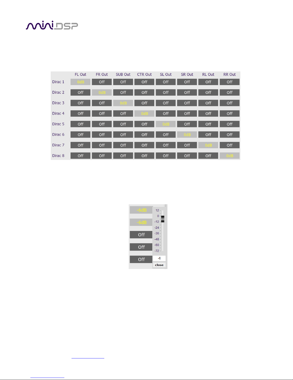
miniDSP Ltd, Hong Kong / www.minidsp.com / Features and specifications subject to change without prior notice 49
8.8 MIXER
This tab mixes the eight signals from the Dirac Live processing and routes them to the individual output
channels. The input channels are labeled along the left and the output channels are labeled along the top.
This is the default setting:
In a typical straightforward surround sound application, each channel from Dirac Live is routed directly to each
output channel. In more sophisticated configurations, each output from Dirac Live might be routed to multiple
output channels to implement active loudspeakers, or for multiple subwoofers.
The gain of the signal being mixed can be adjusted at each crosspoint to a value between -72 and +12 dB.
Note: To rename an output channel, use the Outputs tab.

miniDSP Ltd, Hong Kong / www.minidsp.com / Features and specifications subject to change without prior notice 50
8.9 OUTPUTS
The Outputs tab provides full control over each output channel. Each channel has a “strip” of controls:
8.9.1 Channel label
The name of each output channel is shown at the top of the channel strip. To rename a channel, click on the
channel label and type a new name (up to eight characters).
8.9.2 Gain control and level monitoring
The gain of each channel can be adjusted by moving the Gain Adjustment slider, or by typing the desired gain
into the Current Gain text box. The maximum gain setting is 12 dB, and the minimum gain setting is –72 dB. (0
dB, the default, is unity gain or no change in level.)
The signal level on each output channel displays in two locations: on the bar-graph meter, and as a numeric
value (in dB relative to full scale) in the RMS Level box. The RMS level displays only when the plugin is online.
The level meters are useful in many situations. For example, when adding filters with boost, monitor the level
meters with typical signals and maximum levels to ensure that there is no clipping. The meters can also be used
during normal operation to monitor for or to help locate level or gain structure problems.

miniDSP Ltd, Hong Kong / www.minidsp.com / Features and specifications subject to change without prior notice 51
8.9.3 Parametric EQ
Parametric equalization (PEQ) is a flexible type of equalization filter. It can be used to correct for errors in
loudspeaker output, to compensate for acoustic room effects, and to tailor the overall system response for best
sound. Click on the PEQ button to open the parametric equalizer settings window:
In the center of the window is a frequency response graph that illustrates the combined response of all enabled
parametric filters on that channel. The screenshot above shows a response curve created with a low-shelf boost
filter at 100 Hz, a dip at 500 Hz, and a high-shelf cut filter at 5000 Hz.
There are ten filters per channel, each of which is displayed by clicking on the buttons EQ1, EQ2, and so on. Each
filter can be set to one of four types:
PEAK Create a dip or a peak in the frequency response.
LOW_SHELF Reduce or increase part of the frequency spectrum below a given frequency.
HIGH_SHELF Reduce or increase part of the frequency spectrum above a given frequency.
SUB_EQ Create a dip or a peak in the frequency response at low frequencies (10 to 50 Hz). This filter type
is similar to PEAK but gives more accurate results for low frequencies. Note that activating any
SUB_EQ filter reduces the number of available filters on that channel from ten to nine.
Each filter has three parameters that control its location and shape. These parameters can be entered directly as
numerical values, or by using the sliders:
Frequency For the PEAK and SUB_EQ filter types, this is the center frequency of the peak or dip. For the
HIGH_SHELF and LOW_SHELF filter types, this is the frequency at which the gain is half of the set
value.
Gain For the PEAK and SUB_EQ filter types, this is the gain in dB at the center frequency. For the
HIGH_SHELF and LOW_SHELF filter types, this is the gain in dB reached at high or low
frequencies respectively.

miniDSP Ltd, Hong Kong / www.minidsp.com / Features and specifications subject to change without prior notice 52
Q Q controls the “sharpness” of the filter. For the PEAK and SUB_EQ filter types, lower Q gives a
shallower peak or dip, while higher Q gives a narrower peak or dip. For the HIGH_SHELF and
LOW_SHELF filter types, Q controls how quickly the filter transitions from no gain to maximum
gain.
To disable or enable a filter, click on the Bypass button. A filter will also have no effect if its gain is set to 0.0.
Other filter types can be created by switching to Advanced mode. In this mode, the coefficients of each filter
“biquad” are entered individually. The coefficients will need to be calculated by a filter design program. A useful
spreadsheet for a number of filter types is available on the miniDSP.com website – see the application note
Advanced Biquad Programming.
Each channel can be linked to one other channel. When a channel is linked to another, the PEQ settings of that
channel are mirrored to the other. Typically, the corresponding left and right channels are linked: front left and
right, surround left and right, and rear surround left and right. To link a channel, select the other channel from
the drop-down menu at the top left of the PEQ screen, and click the Link checkbox.

miniDSP Ltd, Hong Kong / www.minidsp.com / Features and specifications subject to change without prior notice 53
8.9.4 Crossover settings
Each output channel has independent high pass and low pass filters. Click on the Xover button to open the
crossover settings window:
By default, the crossover filters are bypassed (disabled). Click on the Bypass button to enable and disable a
crossover filter. There is one filter for high pass (low cut) and one for low pass (high cut). The above example
shows a pair of filters for the subwoofer channel with an 18 Hz high pass filter and an 80 Hz low pass filter.
Each filter can be set to one of a range of filter types and slopes. The filter type determines the shape of the
filter around the crossover point, and the filter slope (expressed in dB/octave) determines how steep the filter
cutoff is. The available filter types and slopes are:
Butterworth (BW)
Available in 6, 12, 18, 24, 30, 36, 42, and 48 dB/octave, Butterworth crossover filters are 3 dB
down at the cutoff frequency.
Linkwitz-Riley (LR)
Available in 12, 24, and 48 dB/octave, Linkwitz-Riley crossover filters are 6 dB down at the cutoff
frequency.
Bessel
Available in 12 dB/octave only, a Bessel filter gives a more gradual roll off through the crossover
region.

miniDSP Ltd, Hong Kong / www.minidsp.com / Features and specifications subject to change without prior notice 54
For other types of filter and filter slopes, use Advanced mode. This mode allows you to enter the coefficients of
eight biquads directly into the interface. The coefficients will need to be calculated by a filter design program. A
useful spreadsheet for a number of filter types is available on the miniDSP.com website – see the application
note Advanced Biquad programming.
Each channel can be linked to one other channel. When a channel is linked to another, the crossover settings of
that channel are mirrored to the other. Typically, the corresponding left and right channels are linked: front left
and right, surround left and right, and rear surround left and right. To link a channel, select the other channel
from the drop-down menu at the top left of the Xover screen, and click the Link checkbox.
8.9.5 Time delay
A delay of up to 1000 ms (1 second) can be applied to each output channel. To set the delay, click in the delay
entry box for a channel. The delay value can be entered numerically, and the up and down arrows can be used
to change the delay in small (0.02 ms) increments.
8.9.6 Invert and mute
Each channel can be inverted in polarity, and individually muted. When either of these options is selected, the
display changes color and the label of the button reflects the current state.

miniDSP Ltd, Hong Kong / www.minidsp.com / Features and specifications subject to change without prior notice 55
9 ADDITIONAL INFORMATION
9.1 SPECIFICATIONS
Computer connectivity
Driverless USB 2.0 control interface for Windows and Mac OS X
Digital inputs
4 x AES/EBU (8 channels) on DB-25 connector (Tascam pinout).
Asynchronous sample rate conversion on each input, sample rates from 32 to 192
kHz accepted.
Digital outputs
4 x AES/EBU (8 channels) on DB-25 connector (Tascam pinout).
If there is a signal on input channels 1 and 2, all output channels have
asynchronous sample rate conversion applied to match that sample rate.
Otherwise, all output channels operate at 48 kHz.
Audio sample rate /
Resolution
Input/output resolution: 24-bit integer
Sample rate: 48 kHz
Audio processing
32-bit floating-point processor
Storage/Presets
4 filter sets stored, selectable from front panel or IR remote
Infrared remote
“Learning remote” capabilities (NEC, Philips, Sony, Apple)
Controls master volume, mute, filter set selection, Dirac Live® filtering enable
Power supply
5 VDC single supply @ 600mA, 2.1 mm center-positive
Dimensions (H x W x D)
41.5 x 214.5 x 206 mm

miniDSP Ltd, Hong Kong / www.minidsp.com / Features and specifications subject to change without prior notice 56
9.2 MCU FIRMWARE UPDATE
miniDSP may occasionally provide an update to the DDRC-88D MCU firmware to enable new features. To update
the MCU firmware, first download and install the latest version of the DDRC-88BM plugin from the User
Downloads section of the miniDSP website. Then follow the instructions below for your platform.
This procedure must also be performed when first using the DDRC-88BM plugin with a DDRC-88D that does not
have a green label indicating “V2.2” or later. This applies to both basic mode and enhanced/bass management
mode.
DO NOT DISCONNECT THE USB CABLE OR POWER FROM THE DDRC-88D WHILE FIRMWARE UPDATE IS
IN PROGRESS. DOING SO MAY “BRICK” YOUR DDRC-88D.
9.2.1 Windows
1. Download and install the latest version of the DDRC-88BM plugin.
2. Connect the DDRC-88D to your computer via USB and power it on.
3. Start the DDRC-88BM plugin.
4. If you have previously used the DDRC-88BM plugin and have configurations that need to be saved, save
them to files now.
5. Click on the Connect button.
a. If your unit does not require requires a firmware upgrade, the connect button will change to a green
tick and you do not have to proceed any further.
b. If your unit does require a firmware upgrade, a warning dialog will pop up. Click OK:
6. The DDRC-88D will automatically be put into boot loader mode and the miniDSP upgrade utility will start.
The status area should display “Device attached”.

miniDSP Ltd, Hong Kong / www.minidsp.com / Features and specifications subject to change without prior notice 57
7. Click on the Open Hex File button and select the .hex file in the firmware folder of the download. It will
have a name like ENC_DDRC88BM_Ver2.22_SS.hex.
8. Click on the Program/Verify button. The status bar will indicate progress. Do not disconnect the USB cable
or remove power from the processor while this runs!
9. After the status indicates that the verify has completed successfully, click on the Reset Device button, and
then quit the upgrade utility.
10. Return to the DDRC-88BM plugin. (If there is a dialog informing "Connection to DSP closed," click on OK.)
Click on the Connect button.
11. You may see the following dialog. This can occur if you upgraded from an earlier DDRC-88D unit without
bass management. (If this does not appear, skip the next step.)
12. If the dialog appears, click on Restore ALL to Default. (If you click on Upgrade & Synchronize, the plugin
will detect a mismatch and you will need to click Restore factory settings in the dialog shown below.)
13. When the plugin connects, the Connect button will change to a green tick.
14. Drop down the Help menu and select About... to verify the new firmware version.

miniDSP Ltd, Hong Kong / www.minidsp.com / Features and specifications subject to change without prior notice 58
9.2.2 Mac OS X
1. Download and install the latest version of the DDRC-88BM plugin.
2. Connect the DDRC-88D to your computer via USB and power it on.
3. Start the DDRC-88BM plugin.
4. If you have previously used the DDRC-88BM plugin and have configurations that need to be saved, save
them to files now.
5. Click on the Connect button.
a. If your unit does not require requires a firmware upgrade, the connect button will change to a green
tick and you do not have to proceed any further.
c. If your unit does require a firmware upgrade, a warning dialog will pop up. Click OK:
6. The DDRC-88D will be put into boot loader mode and the miniDSP bootloader program will start. The status
area should display “Device attached” and then “Device Ready.”
7. Click on the Import Firmware Image button and select the .hex file located in the firmware folder of the
download. It will have a name like ENC_DDRC88BM_Ver2.22_SS.hex.

miniDSP Ltd, Hong Kong / www.minidsp.com / Features and specifications subject to change without prior notice 59
8. Click on the Erase/Program/Verify Device button. The status display will indicate progress. Do not
disconnect the USB cable or remove power from the processor while this runs!
9. After the status indicates that the verify has completed successfully, click on the Reset Device button, and
then quit the bootloader program.
10. Return to the DDRC-88BM plugin. (If there is a dialog informing "Connection to DSP closed," click on OK.)
Click on the Connect button.
11. You may see the following dialog. This can occur if you upgraded from an earlier DDRC-88D unit without
bass management. (If this does not appear, skip the next step.)
12. If the dialog appears, click on Restore ALL to Default. (If you click on Upgrade & Synchronize, the plugin
will detect a mismatch and you will need to click Restore factory settings in the dialog shown below.)
13. When the plugin connects, the Connect button will change to a green tick.
14. Drop down the Help menu and select About... to verify the new firmware version.

miniDSP Ltd, Hong Kong / www.minidsp.com / Features and specifications subject to change without prior notice 60
9.3 ACTIVATING ENHANCED/BASS MANAGEMENT MODE
The following procedure converts a DDRC-88D from basic mode to enhanced/bass management mode. It only
needs to be applied to a DDRC-88D that was purchased in basic mode, after later purchasing the plugin upgrade
from the miniDSP website:
• https://www.minidsp.com/products/dirac-series/ddrc-88bm
The DDRC-88D must be running the current firmware before doing this step. See Section 9.2 MCU
Firmware update.
1. Download and install the latest version of the DDRC-88BM plugin from the miniDSP.com website.
2. Start the plugin and click the Connect button.
3. Drop down the Help menu and select “Activate Bass Management”.
4. The following screen will appear:
5. Click on the button “Copy Activation Code to Clipboard.”
6. Send an email message to info@minidsp.com with the Subject line “DDRC-88-BM Activation Request.” In
the body of the email message, paste the activation code. miniDSP will respond in normal (Hong Kong)
working hours with an activation key file (.txt file). (Please note that this is not an automated process.) The
activation key file contains a key text string consisting of 128 pairs of letters separated by spaces (total 256
letters).
7. Click the “Import” button and select the received activation key file to import into the plugin. If successful,
you will then see the normal connection dialog box (as on page 43).

miniDSP Ltd, Hong Kong / www.minidsp.com / Features and specifications subject to change without prior notice 61
9.4 TROUBLESHOOTING
The following table lists the most common causes of issues with the DDRC-88D. If following this table does not
provide a solution, see Obtaining Support.
DDRC-88BM plugin
1
Cannot install
software
a. Confirm that you downloaded and installed the required frameworks
first (see Software Installation).
2
Plugin running in
background but not
showing
a. The Adobe Air environment may need a network connection the first
time you run a plugin. Close the plugin program, ensure that your
computer has a network connection, and restart the plugin.
b. The Adobe Air environment may require a version update. Download
the latest version from http://get.adobe.com/air/.
3
Plugin cannot
connect
a. Check that the USB cable to the DDRC-88D is firmly connected
b. Reset the processor by power-cycling the unit.
4
No signal showing
on Dirac Live input
meters
a. Check the cabling from your source.
b. Check that your source is playing audio and that it is not muted or have
volume control turned down.
c. Check that the plugin is synchronized with the hardware unit.
5
Low audio on
outputs
a. Check all downstream cabling (DAC, amplification, speakers).
b. Check that amplifiers are turned on and that any volume controls are
turned up.
c. Check that the input and output meters are showing signal.
d. Check that master mute is not enabled.
e. Check the master volume level.
f. Check that your crossover frequencies are correct e.g. that you don’t
have high pass and low pass frequencies incorrectly set.
g. Check that the matrix mixer is sending the correct inputs to the correct
outputs.
6
Audio sounds
distorted
a. Check the output meter and ensure that you are not overloading the
outputs. If necessary, reduce the output gain and/or the amount of
boost in the EQ blocks.
7
Audio is coming
through the wrong
outputs
a. Check downstream cabling (DAC, amplification, speakers).
b. Check that you have correctly set up the matrix mixer to send the
correct inputs to the correct outputs.
8
Cannot reload a
configuration
a. Confirm the file format of your file (.xml).
b. Confirm the version of the file.

miniDSP Ltd, Hong Kong / www.minidsp.com / Features and specifications subject to change without prior notice 62
Dirac Live Calibration Tool
1
The DDRC-88D
doesn’t appear in the
Sound System tab
a. Check that the USB cable to the DDRC-88D is firmly connected.
b. Check that you are not running the DDRC-88BM plugin.
c. Check that you have the miniDSP version of the software installed,
called Dirac Live Calibration Tool For miniDSP.
d. Go to the Sound System tab and click the Rescan button.
2
The measurement
test signal produces
no output
a. Ensure that the DDRC-88D processor is connected correctly into the
audio system.
b. Check that the downstream amplification is powered on.
c. Check that the downstream amplification is not muted and doesn’t
have gain/trim controls set to zero.
d. Quit DLCT, open the DDRC-88BM plug and click Connect. Connect an
analog source to the inputs, and confirm that signal levels are seen on
output meters.
3
No input from
measurement
microphone
a. Check that the USB cable to the UMIK-1 is securely seated.
b. Check that the UMIK-1 is selected in the Mic Config tab.
c. Remove any USB hubs and extensions.
4
Insufficient recording
level
a. Increase microphone level in the Output & Levels tab.
b. Go to the Control Panel and view the Recording tab of the Sound pane.
Select the UMIK-1 and view its Properties. In Levels, set the gain to 100.
c. Increase system output volume.
5
Unable to generate
correction filters
(Optimize button)
a. Check that your computer is connected to the Internet and able to pass
HTTP (web) traffic.
b. Check that you do not have any other program running that is
attempting to communicate with the DDRC-88D, such as the DDRC88BM plugin.
9.5 OBTAINING SUPPORT
1. Check the forums on miniDSP.com to see if this issue has already been raised and a solution or solutions
provided.
2. Contact miniDSP via the support portal at minidsp.desk.com with:
a. The product information obtained from DDRC-88BM plugin (Help -> About...) and Dirac Live
Calibration Tool for miniDSP (Sound System tab) while the plugin is online.
b. A clear explanation of the symptoms you are seeing.
c. A description of the troubleshooting steps you performed (see Troubleshooting on page 61) and the
results obtained.
 Loading...