

miniDSP C-DSP 8X12 DL User Manual
PRELIMINARY
miniDSP Ltd, Hong Kong / www.minidsp.com / Features and specifications subject to change without prior notice 1
C-DSP 8X12 DL
8-IN 12-OUT ADVANCED IN-CAR AUDIO PROCESSOR
WITH DIRAC LIVE® ACOUSTIC CORRECTION
PRELIMINARY
User Manual

PRELIMINARY
miniDSP Ltd, Hong Kong / www.minidsp.com / Features and specifications subject to change without prior notice 2
Revision history
Revision
Description
Date
V0.1
Preliminary version for Dirac Live
3 April 2019
V0.4
Preliminary public release
20 May 2019

PRELIMINARY
miniDSP Ltd, Hong Kong / www.minidsp.com / Features and specifications subject to change without prior notice 3
CONTENTS
Important Information ...................................................................................................................................6
1 Product Overview ....................................................................................................................................9
1.1 Typical usage ..............................................................................................................................................9
1.2 Dirac Live ................................................................................................................................................. 11
1.3 Overview of configuration steps ............................................................................................................. 12
2 Software Installation .............................................................................................................................. 13
2.1 Download the software ........................................................................................................................... 13
2.2 Software installation ― Windows ........................................................................................................... 14
2.3 Software installation ― macOS / OS X .................................................................................................... 15
3 Hardware Connectivity........................................................................................................................... 16
3.1 Analog inputs ........................................................................................................................................... 16
3.1.1 Low-level inputs ............................................................................................................................... 16
3.1.2 High-level inputs .............................................................................................................................. 17
3.2 Digital input ............................................................................................................................................. 18
3.3 Analog outputs ........................................................................................................................................ 18
3.4 DC power ................................................................................................................................................. 19
3.4.1 Powered on power (position 1) ....................................................................................................... 19
3.4.2 Remote trigger (position 2) ............................................................................................................. 19
3.5 Wired remote .......................................................................................................................................... 20
3.6 USB .......................................................................................................................................................... 20
4 Plugin Overview ..................................................................................................................................... 21
4.1 User interface .......................................................................................................................................... 21
4.2 Synchronizing with the processor ........................................................................................................... 22
4.3 Global controls ........................................................................................................................................ 23
4.3.1 Configuration/preset selection........................................................................................................ 23
4.3.2 Tab selection .................................................................................................................................... 23
4.3.3 Digital input selection ...................................................................................................................... 23
4.3.4 Master mute .................................................................................................................................... 23
4.3.5 IP Address and Auto ........................................................................................................................ 24
4.3.6 Subwoofer and Master volume ....................................................................................................... 24
4.3.7 Dirac Live on/off .............................................................................................................................. 24
4.4 Signal flow ............................................................................................................................................... 25
4.5 Inputs & Bass Mgt tab ............................................................................................................................. 26
4.6 Routing tab .............................................................................................................................................. 27
4.7 Dirac Live tab ........................................................................................................................................... 28
4.8 Mixer tab ................................................................................................................................................. 29
4.9 Output tabs .............................................................................................................................................. 30
4.10 Application guide ..................................................................................................................................... 31
4.10.1 Straight through .............................................................................................................................. 31
4.10.2 Bass management ........................................................................................................................... 32

PRELIMINARY
miniDSP Ltd, Hong Kong / www.minidsp.com / Features and specifications subject to change without prior notice 4
4.10.3 Dual subwoofers .............................................................................................................................. 33
4.10.4 Active crossover ............................................................................................................................... 34
4.10.5 Rear channel synthesis .................................................................................................................... 35
5 Acoustic Measurement for Dirac Live ..................................................................................................... 36
5.1 Overview .................................................................................................................................................. 36
5.2 Connections ............................................................................................................................................. 37
5.3 Some notes and cautions before you begin ............................................................................................ 38
5.3.1 Ensure good measurement conditions............................................................................................ 38
5.3.2 Select the configuration/preset ...................................................................................................... 38
5.3.3 Check subwoofer volume ................................................................................................................ 38
5.3.4 Only run one program at a time ...................................................................................................... 38
5.3.5 Don’t take shortcuts ........................................................................................................................ 38
5.4 Saving and loading projects ..................................................................................................................... 38
5.5 Configuring for measurement ................................................................................................................. 39
5.5.1 Sound System tab ............................................................................................................................ 40
5.5.2 Mic Config tab .................................................................................................................................. 41
5.5.3 Output & Levels tab ......................................................................................................................... 42
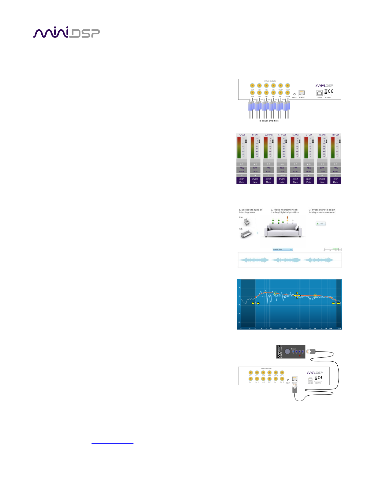
5.6 Running the measurements .................................................................................................................... 43
5.6.1 Select listening environment ........................................................................................................... 43
5.6.2 About measurement locations ........................................................................................................ 43
5.6.3 Execute a measurement .................................................................................................................. 44
5.6.4 If you receive an error ..................................................................................................................... 45
5.6.5 Viewing and redoing measurements ............................................................................................... 45
5.6.6 Completing the measurements ....................................................................................................... 45
6 Dirac Live Filter Design ........................................................................................................................... 46
6.1 Working with graphs ............................................................................................................................... 48
6.2 Designing your target curve .................................................................................................................... 49
6.2.1 The Auto Target ............................................................................................................................... 49
6.2.2 Editing the target curve ................................................................................................................... 49
6.2.3 Guidelines for target curve design .................................................................................................. 50
6.2.4 Saving and loading target curves ..................................................................................................... 51
6.3 Generating correction filters ................................................................................................................... 52
6.4 Loading filter sets .................................................................................................................................... 53
7 Remote Control ..................................................................................................................................... 54
7.1 Status indicators ...................................................................................................................................... 54
7.2 Operation of the wired remote ............................................................................................................... 54
7.3 Channel selection for subwoofer volume control ................................................................................... 55
7.4 Using the miniDSP infrared remote ......................................................................................................... 56
7.5 Learning third-party remote codes ......................................................................................................... 57
8 Plugin Reference .................................................................................................................................... 58
8.1 Output channel processing ...................................................................................................................... 58
8.1.1 Channel label ................................................................................................................................... 58

PRELIMINARY
miniDSP Ltd, Hong Kong / www.minidsp.com / Features and specifications subject to change without prior notice 5
8.1.2 Level meter and gain control ........................................................................................................... 58
8.1.3 Parametric EQ (PEQ) ........................................................................................................................ 59
8.1.4 Crossover (Xover) ............................................................................................................................ 61
8.1.5 Time delay ....................................................................................................................................... 63
8.1.6 Invert and mute ............................................................................................................................... 63
8.2 Custom biquad programming .................................................................................................................. 64
8.2.1 What’s a “biquad? ........................................................................................................................... 64
8.2.2 Using custom biquad programming ................................................................................................ 64
8.2.3 Biquad design software ................................................................................................................... 66
8.3 Working with configurations ................................................................................................................... 67
8.3.1 Online and offline mode .................................................................................................................. 67
8.3.2 Selecting a configuration ................................................................................................................. 67
8.3.3 Saving and loading configurations ................................................................................................... 68
8.3.4 Loading configurations from microSD card ..................................................................................... 68
8.3.5 Restoring to defaults ....................................................................................................................... 69
8.4 Keyboard shortcuts ................................................................................................................................. 69
9 Additional information ........................................................................................................................... 70
9.1 Specifications ........................................................................................................................................... 70
9.2 Input sensitivity setting ........................................................................................................................... 71
9.3 Remote trigger timing ............................................................................................................................. 72
9.4 Acoustic measurement setup for REW .................................................................................................... 73
9.5 Troubleshooting ...................................................................................................................................... 74
9.5.1 C-DSP 8x12 DL plugin ....................................................................................................................... 74
9.5.2 DLCT ................................................................................................................................................. 75
9.6 Firmware upgrade ................................................................................................................................... 76
9.7 Obtaining support .................................................................................................................................... 76

PRELIMINARY
miniDSP Ltd, Hong Kong / www.minidsp.com / Features and specifications subject to change without prior notice 6
IMPORTANT INFORMATION
Please read the following information before use. In case of any questions, please contact miniDSP via the
support portal at minidsp.desk.com.
System Requirements
To configure the miniDSP audio processor, you will require a Windows PC or Apple Mac OS X computer with the
following minimum specification:
Windows
• Intel Pentium III or later, AMD Athlon XP or later
• 2 Gigabytes (GB) of RAM or higher
• Keyboard and mouse or compatible pointing device
• Microsoft• ® Windows® Vista® SP1/Win7/Win8/Win10
• Two free USB 2.0 ports
Mac OS X
• Intel-based Mac with 1 GHz or higher processor clock speed
• 2 Gigabytes (GB) of RAM or higher
• Keyboard and mouse or compatible pointing device
• OS X 10.9 (Mavericks) or later, macOS 10.12 (Sierra) or later
• Two free USB 2.0 ports
Disclaimer/Warning
miniDSP cannot be held responsible for any damage that may result from the improper use of this product or
incorrect configuration of its settings. As with any other product, we recommend that you carefully read this
manual and other technical notes to ensure that you fully understand how to operate this product. The miniDSP
audio processor is a powerful tool, and misuse or misconfiguration, such as incorrectly set gains or excessive
boost, can produce signals that may damage your audio system.
As a general guideline, you should perform the initial configuration of the miniDSP audio processor before
enabling audio through any connected output device or amplification. Doing so will help ensure that the
software is correctly configured.
Finally, note that the miniDSP audio processor is a very flexible device, and many of the questions we receive at
the tech support department are already answered in this user manual and in the online application notes on
the miniDSP.com website. So please take the time to carefully read this user manual and the online technical
support. Thanks for your understanding!

PRELIMINARY
miniDSP Ltd, Hong Kong / www.minidsp.com / Features and specifications subject to change without prior notice 7
Warranty Terms
miniDSP Ltd warrants this product to be free from defects in materials and workmanship for a period of one
year from the invoice date. Our warranty does not cover failure of the product due to incorrect connection or
installation, improper or undocumented use, unauthorized servicing, modification or alteration of the unit in any
way, or any usage outside of that recommended in this manual. If in doubt, contact miniDSP prior to use.
FCC Class B Statement
This device complies with Part 15 of the FCC Rules. Operation is subject to the following two conditions:
• This device may not cause harmful interference.
• This device must accept any interference received, including interference that may cause undesired
operation.
Warning: This equipment has been tested and found to comply with the limits for a Class B digital device,
pursuant to Part 15 of the FCC Rules. These limits are designed to provide reasonable protection. This
equipment generates, uses and can radiate radio frequency energy and, if not installed and used in accordance
with the instructions, may cause interference to radio communications. However, there is no guarantee that
interference will not occur in a particular installation. If this equipment does cause harmful interference to radio
or television reception, which can be determined by turning the equipment off and on, the user is encouraged to
try to correct the interference by one or more of the following measures:
• Reorient or relocate the receiving antenna.
• Increase the separation between the equipment and receiver.
• Connect the equipment into an outlet on a circuit different from that to which the receiver is connected.
• Consult the dealer or an experienced radio/TV technician for help.
Notice: Shielded interface cable must be used in order to comply with emission limits.
Notice: Changes or modification not expressly approved by the party responsible for compliance could void the
user’s authority to operate the equipment.
CE Mark Statement
The C-DSP 8x12 DL has passed the test performed according to European Standard EN 55022 Class B.
PRELIMINARY
miniDSP Ltd, Hong Kong / www.minidsp.com / Features and specifications subject to change without prior notice 8
A Note on this Manual
This User Manual is designed for reading in both print and on the computer. If printing the manual, please print
double-sided. The embedded page size is 8 ½” x 11”. Printing on A4 paper will result in a slightly reduced size.
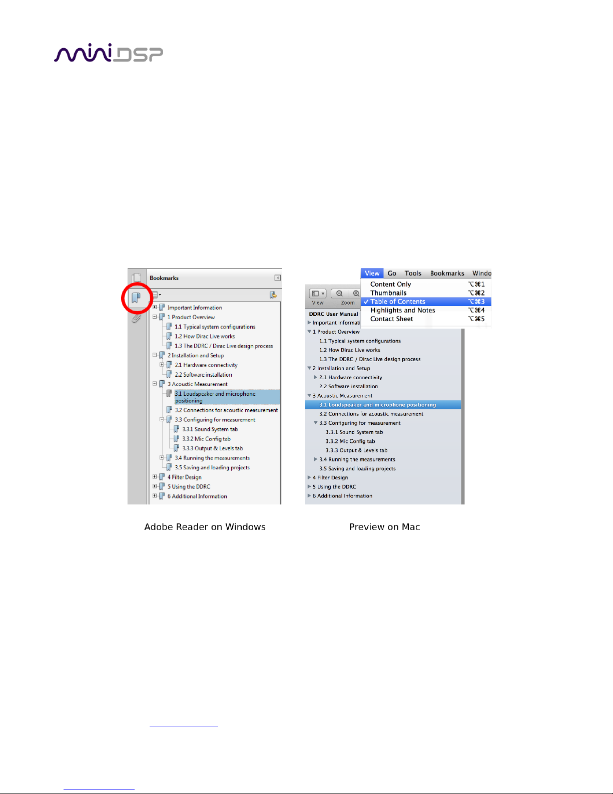
For reading on the computer, we have included hyperlinked cross-references throughout the manual. In
addition, a table of contents is embedded in the PDF file. Displaying this table of contents will make navigation
much easier:
• In Adobe Reader on Windows, click on the “bookmarks” icon at the left. The table of contents will appear on
the left and can be unfolded at each level by clicking on the “+” icons.
• In Preview on the Mac, click on the View menu and select Table of Contents. The table of contents will
appear on the left and can be unfolded at each level by clicking on the triangle icons.
PRELIMINARY
miniDSP Ltd, Hong Kong / www.minidsp.com / Features and specifications subject to change without prior notice 9
1 PRODUCT OVERVIEW
Thank you for choosing the miniDSP C-DSP 8x12 DL advanced in-car audio processor. The C-DSP 8x12 DL
features an onboard isolated power supply, two stereo digital inputs, 6 analog inputs, 12 analog outputs, a full
eight channels of Dirac Live room correction and miniDSP’s powerful audio processing on each output channel.
By use of the onboard matrix mixers, the C-DSP 8x12 DL is adaptable to many configurations, ranging from a
simple stereo correction and EQ system, through to integration of one or more subwoofers, through to a
complete active multichannel surround system. Low-noise analog circuitry driven by a 32-bit AKM convertor
ensures pristine audio quality in any vehicle environment.
Four complete processing configurations are stored on-board and can be selected from the wired remote or by
infrared remote control. An SD card slot supports offline configuration and firmware upgrade.
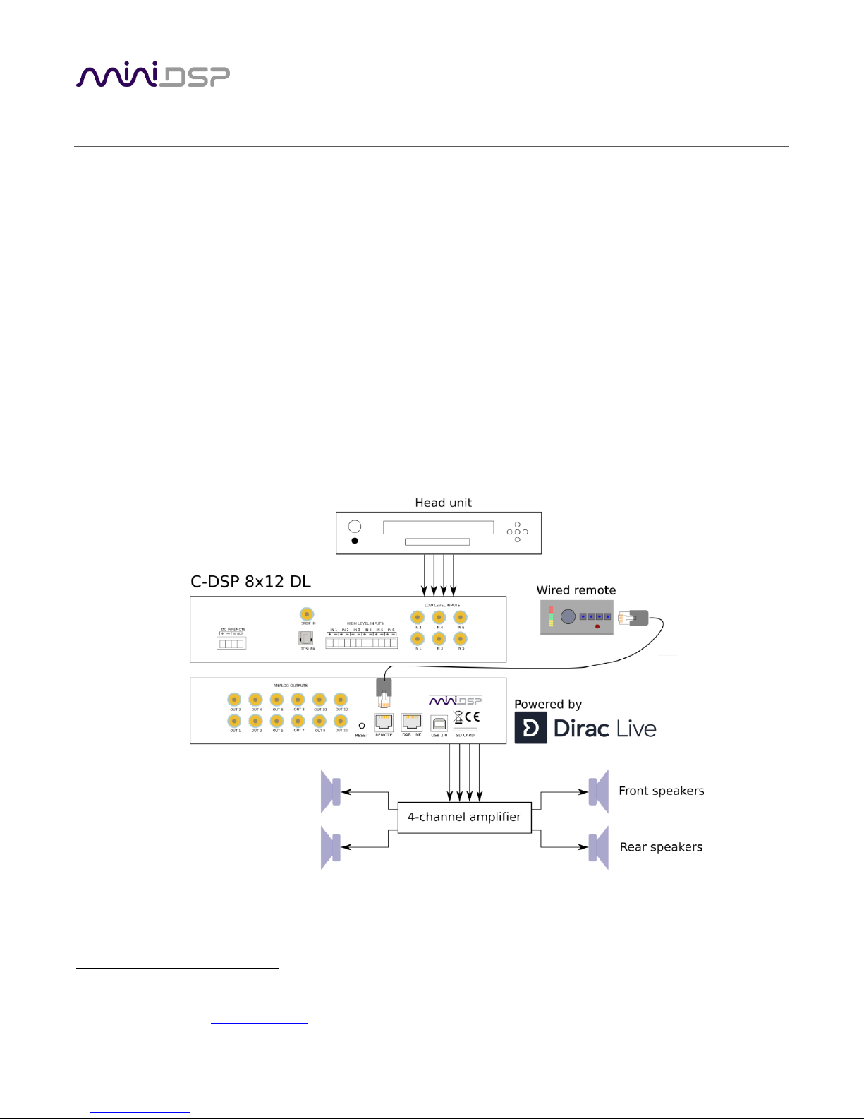
1.1 TYPICAL USAGE
The C-DSP 8x12 DL typically connects to a head unit with up to six outputs. Figure 1 illustrates a straightforward
installation, with four channels supplied by the head unit and four speakers being driven by a power amplifier.
The included miniDSP UMIK-1 is used to perform Dirac Live calibration.1
1
Note that the miniDSP version of Dirac Live Calibration Tool requires a miniDSP UMIK-1 Other microphones cannot be used.
Figure 1. Basic system setup with four-channel acoustic correction
PRELIMINARY
miniDSP Ltd, Hong Kong / www.minidsp.com / Features and specifications subject to change without prior notice 10
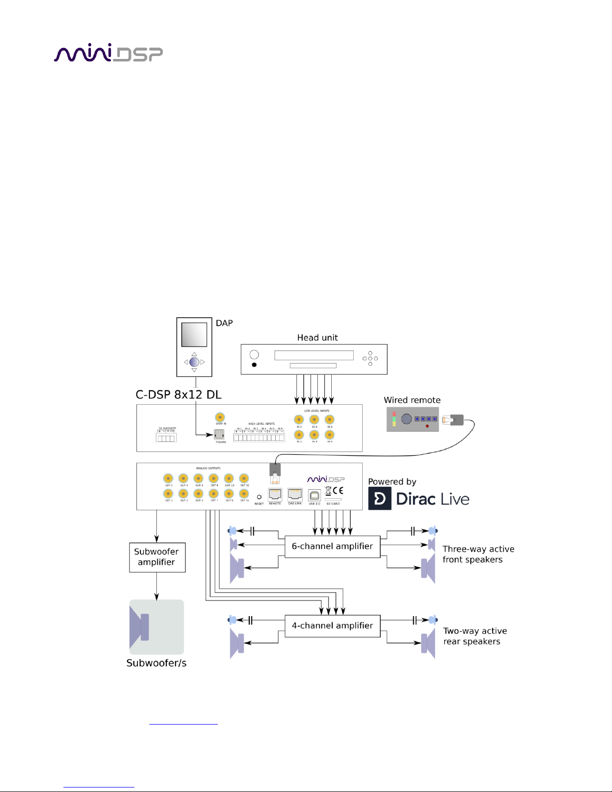
The C-DSP 8x12 DL also supports more advanced configurations. With up to 12 output channels, implementing
an in-vehicle active speaker system has never been easier, and the Dirac Live correction ensures optimum
response all around. Some features include:
• From stereo up to full 5.1 surround input from head unit supported.
• Comprehensive bass management function to synthesize the subwoofer feed from speaker channels.
• Up to 8 channels of Dirac Live correction with flexible assignment to output channels.
• Stereo digital input source switchable to any combination of outputs.
• Rear channel synthesis for stereo sources.
• Multiple onboard configurations for different situations (with/without passengers, competition etc.).
Figure 2 illustrates a more complex installation that uses more of the features of the C-DSP 8x12 DL. While
designed specifically for car use, the advanced features and high performance of the C-DSP 8x12 DL also make
its use feasible in other situations where complex multichannel processing is needed, such as homes, recording
studios, churches and halls, and exhibitions.
Figure 2. Advanced system configuration with multiple sources and active speakers
PRELIMINARY
miniDSP Ltd, Hong Kong / www.minidsp.com / Features and specifications subject to change without prior notice 11
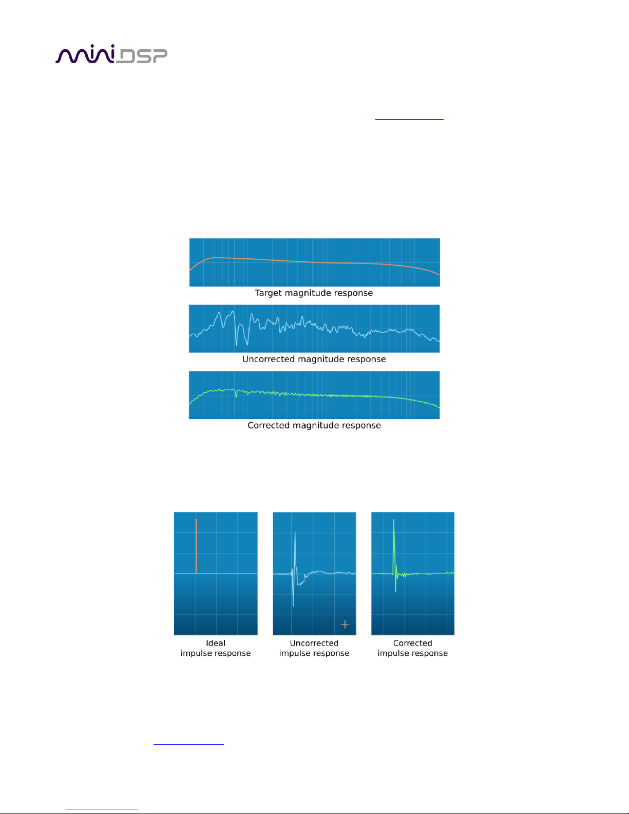
1.2 DIRAC LIVE
The C-DSP 8x12 DL executes Dirac Live® digital room correction, from Dirac Research. This mixed-phase filtering
technology will minimize the effects of cabin modes and resonances, adjust frequency response to optimum,
and improve imaging, dynamics and clarity.
To accomplish its remarkable improvement in listening quality, the Dirac Live Calibration Tool (DLCT) steps you
through the procedure for taking measurements around your listening area. Dirac Live® employs a sophisticated
analysis algorithm to make the optimal correction across the whole listening area, not just at a single point. The
user has full control over the target response. Measurements are taken with a calibrated acoustic measurement
microphone, the miniDSP UMIK-1.
In addition to correcting frequency response, Dirac Live® corrects the system’s impulse response, which reflects
how the system responds to a sharp transient such as a drumbeat. Reflections, diffraction, resonances,
misaligned drivers, and so on, all combine to smear out the transient. Correcting the impulse response makes
the speaker behave much more like an ideal speaker.
The C-DSP 8x12 DL provides, in addition to Dirac Live, a full suite of miniDSP’s audio processing functions on
each channel. Combined with two flexible matrix mixers for audio routing, this enables advanced applications
such as in-vehicle active crossovers to be corrected by Dirac Live, all in a compact 12V-powered unit.
PRELIMINARY
miniDSP Ltd, Hong Kong / www.minidsp.com / Features and specifications subject to change without prior notice 12
1.3 OVERVIEW OF CONFIGURATION STEPS
The steps for configuring the C-DSP 8x12 DL with Dirac Live® are summarized as follows:
1. Connect the C-DSP 8X12 DL audio processor into your system and
install software. See Section 2, Hardware Connectivity and Section 3,
Software Installation.
2. Configure output channel processing with the C-DSP 8x12 DL plugin.
This sets up individual control of each output channel in order to
implement (for example) subwoofer crossover, active speaker
crossovers, or rear/center synthesis. See Section 4, Plugin
Overview.
3. Run a series of acoustic measurements using the Dirac Live
Calibration Tool program, to capture the acoustic behavior of your
speakers and acoustic environment. See Section 5, Acoustic
Measurement for Dirac Live.
4. Generate digital correction filters that will be executed by the C-DSP
8x12 DL. Up to four filter sets can be downloaded into the processor
for easy real-time recall and auditioning. See Section 6, Dirac Live
Filter Design.
5. Once configuration is complete, the computer is not needed. See
Section 7, Remote Control.
PRELIMINARY
miniDSP Ltd, Hong Kong / www.minidsp.com / Features and specifications subject to change without prior notice 13
2 SOFTWARE INSTALLATION
The C-DSP 8x12 DL is configured by software running on a PC or Mac.
2.1 DOWNLOAD THE SOFTWARE
If you purchased your product directly from miniDSP, your software will be available from the User Downloads
section of the miniDSP website when your order ships.
If you purchased your product from a miniDSP dealer, you will receive a coupon together with the product.
Redeem this coupon and select the Plugin Group “miniDSP C-DSP 8x12” at the link below:
• https://www.minidsp.com/support/redeem-coupon
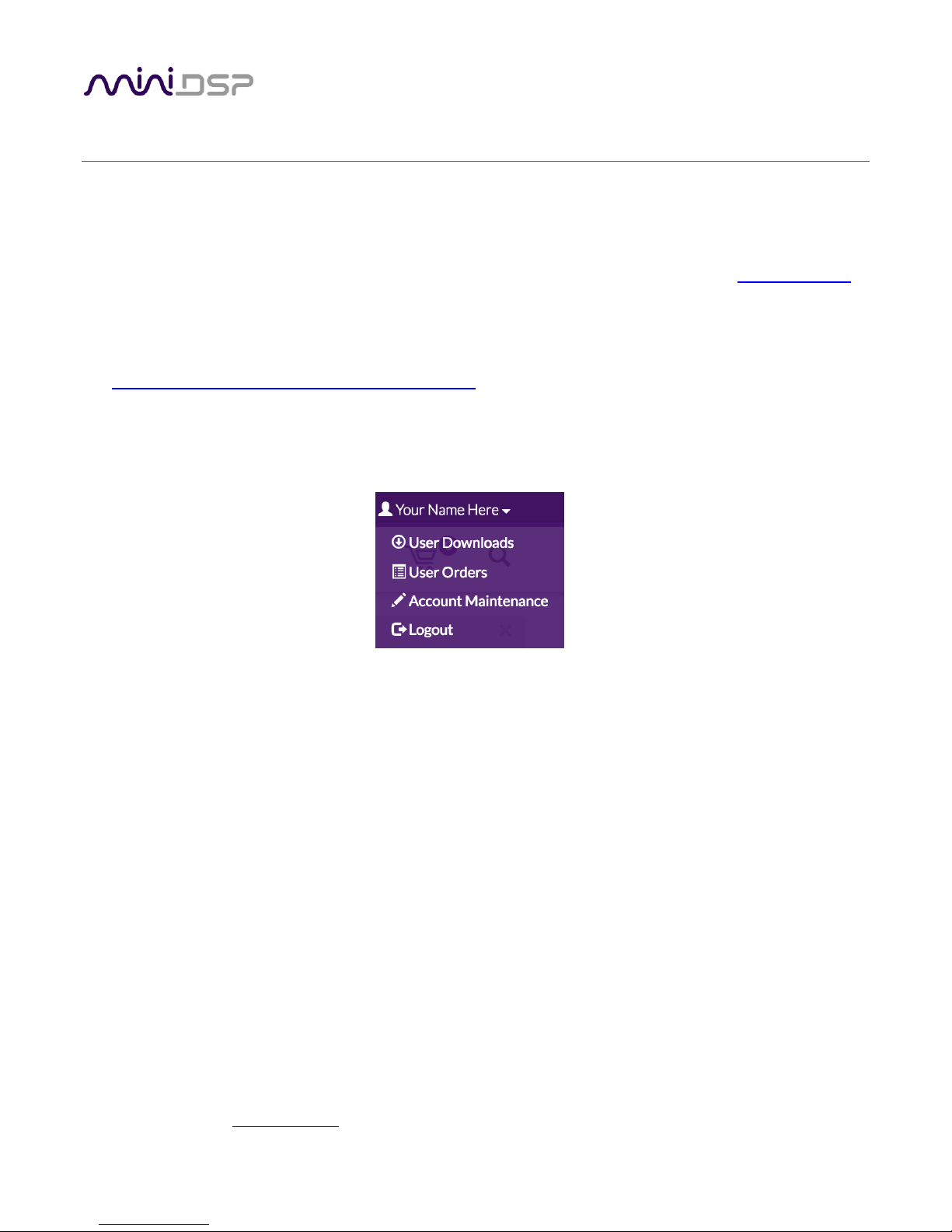
To access the download, you will need to be logged into the miniDSP.com website with the account you created
when purchasing. The User Downloads link is visible from the dropdown menu at the top right of the website
page:
Navigate to the C-DSP plug-ins section and download the zip file under the heading C-DSP 8x12 DL plugin. Unzip
the downloaded file: on Windows, right-click and select “Extract All...”; on Mac, double-click. ). The unzipped
download has a name like C_DSP_8x12_DL_v1_2 and will contain the following folders:
Dirac Live
This folder contains the installers for Dirac Live Calibration Tool for miniDSP (DLCT) stereo version,
which is used to perform the Dirac Live calibration, including taking measurements, generating
correction filters, and loading them into the processor. There are separate Windows and Mac versions.
Plugins
This folder contains the installers for the C-DSP 8x12 DL plugin, used to set up non-Dirac signal
processing, configure remote control codes and perform various other maintenance operations on the
processor. There are separate Windows and Mac versions.
firmware
This folder contains the firmware for the processor. See Firmware Upgrade on page 76.
PRELIMINARY
miniDSP Ltd, Hong Kong / www.minidsp.com / Features and specifications subject to change without prior notice 14
2.2 SOFTWARE INSTALLATION ― WINDOWS
Possible Windows installation issues
The miniDSP software requires that a number of other frameworks be installed for it to work. For Windows 7
and later, these packages should be installed automatically. For earlier versions of Windows, please download
and install the following frameworks before attempting to install any miniDSP software. You can also manually
install these if you receive an error message that required software is missing.
• Microsoft .NET framework (version 3.5 or later)
• Latest version of Adobe Air
• Microsoft Visual C++ 2010 Redistributable Package: for x86 (32-bit operating system) or x64 (64-bit operating
system).
C-DSP 8x12 DL plugin installation
1. Navigate to the Plugins folder of the software download and then to the Windows folder.
2. Double-click on the C_DSP_8x12_DL.exe installer program to run it. We recommend that you accept the
default installation settings.
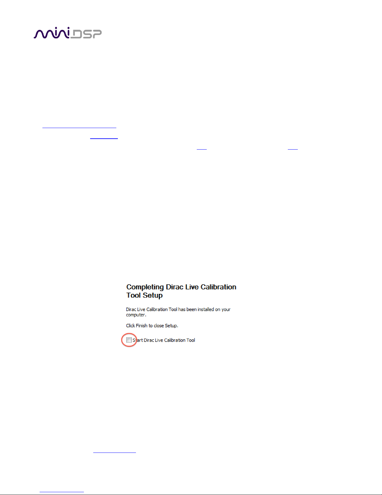
Dirac Live Calibration Tool (DLCT) installation
1. Navigate to the Dirac Live folder of the software download and then to the Windows folder.
2. Double-click on the installer to run it. The installer will have a name similar to Dirac Live Calibration Tool
v1.2.41.8863 Setup.exe (the version number starting with v1.2... may be different). We recommend that
you accept the default installation settings. However, on the last screen, uncheck the box to start Dirac Live
automatically (you will need to install the driver as described on the next page before using DLCT).
Note 1: The Adobe Air framework may need to connect to the Internet the first time you run the plugin.
Note 2: The first time you run the plugin, you may see a warning from Windows Firewall asking whether the
software should be allowed network access. If you do, ensure that “Private networks...” is checked and “Public
networks...” is not checked. Then click on “Allow access.”
PRELIMINARY
miniDSP Ltd, Hong Kong / www.minidsp.com / Features and specifications subject to change without prior notice 15
2.3 SOFTWARE INSTALLATION ― MACOS / OS X
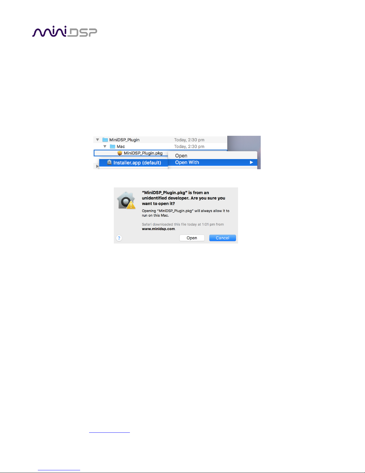
Possible Mac installation issues
If double-clicking on an installer brings up a message that the installer cannot run, use this alternate method
(note that the name of the plugin will be C-DSP-8x12-DL.pkg, not MiniDSP_Plugin.pkg as shown in the example
screenshots):
1. Right-click on the installer (or click while holding the Control key).
2. Move the mouse over the “Open With” item and then click on “Installer (default).”
3. The following window will appear. Click on “Open.”
C-DSP 8x12 DL plugin installation
1. Navigate to the Plugins folder of the software download and then to the Mac folder.
2. The installer program is named C-DSP-8x12-DL.pkg. To run it, double-click on it, or right-click and open as
described above. We recommend that you accept the default installation settings.
3. To run the plugin, locate C-DSP-8x12-DL.app in the Applications -> miniDSP folder and double-click on it. To
make it easier to run in future, right-click on its dock icon and select Options -> Keep in Dock.
Note: The Adobe Air framework may need to connect to the Internet the first time you run the plugin.
Dirac Live Calibration Tool (DLCT) installation
1. Navigate to the Dirac Live folder of the software download and then to the Mac folder.
2. The installer program will have a name similar to Dirac Live Calibration Tool v1.2.41.8863.pkg (the version
number starting with v1.2... may be different). To run it, double-click on it, or right-click and open as
described above. We recommend that you accept the default installation settings.
3. To run DLCT, locate Dirac Live Calibration Tool.app in the Applications -> miniDSP folder and double-click
on it. To make it easier to run in future, right-click on its dock icon and select Options -> Keep in Dock.

PRELIMINARY
miniDSP Ltd, Hong Kong / www.minidsp.com / Features and specifications subject to change without prior notice 16
Figure 3. Single-ended RCA connection
Figure 4. Connecting a balanced source to the C-DSP 8x12 DL.
3 HARDWARE CONNECTIVITY
Connections to the C-DSP 8x12 DL are made on the front and rear panels.
3.1 ANALOG INPUTS
3.1.1 Low-level inputs
Low-level analog connections are made directly to the RCA jacks on the front panel. Be sure to take careful note
of the channel numbering shown in this diagram and on the front panel. These inputs accept a maximum input
voltage of either 2 or 4 VRMS, depending on the input sensitivity switch setting (see page 71).
Note that these are fully differential inputs. A regular RCA-RCA cable be used to connect from equipment with
single-ended outputs, as shown in Figure 3.
If connecting to equipment with balanced output, connect the negative or “cold” leg to the RCA shield and the
positive or “hot” leg to the RCA tip, as shown in Figure 4.
PRELIMINARY
miniDSP Ltd, Hong Kong / www.minidsp.com / Features and specifications subject to change without prior notice 17
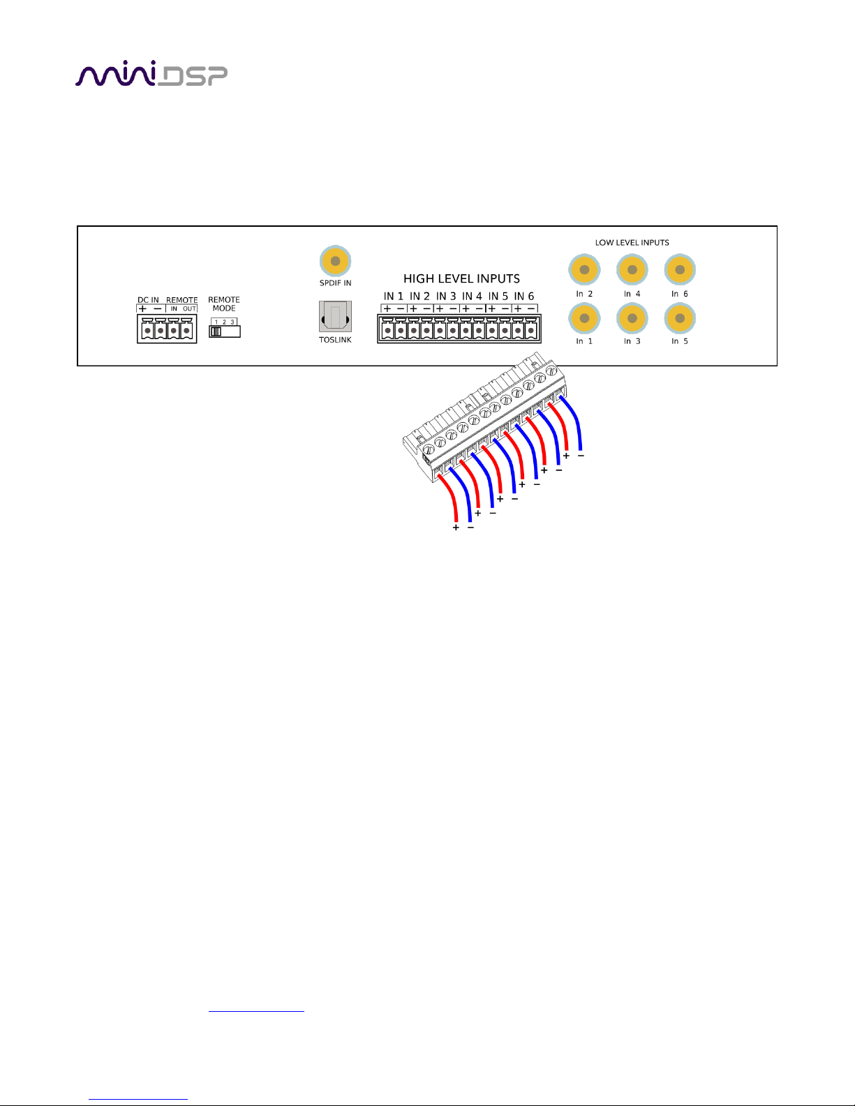
3.1.2 High-level inputs
High-level (speaker-level) connections can be made by connecting bare wire ends to the push-in terminal block.
Remove the terminal block and connect individual positive and negative wires to each screw terminal. After all
connections are secure, firmly re-insert the terminal block.
The high-level inputs have an input impedance of 68 Ω and are designed for connection to the speaker outputs
of a head unit. The inputs are fully differential, therefore:
• Amplifiers with bridged outputs can be used.
• Do not connect the “–” outputs together. This can potentially damage the amplifiers in your head unit.
The maximum (differential) input voltage is either 8 or 12 V RMS, depending on the input sensitivity switch
setting (see page 71). The 8 V RMS setting corresponds to a maximum amplifier power of 16 Watts into 4 ohms.
The 12 V RMS setting corresponds to a maximum amplifier power of 36 Watts into 4 ohms.
PRELIMINARY
miniDSP Ltd, Hong Kong / www.minidsp.com / Features and specifications subject to change without prior notice 18
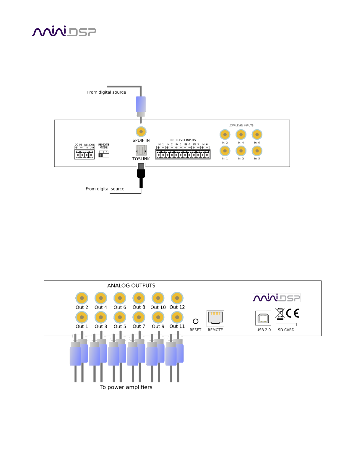
3.2 DIGITAL INPUT
Two digital sources can be connected via the S/PDIF coax (RCA) connector and the TOSLINK (optical) connector.
Switching between sources can be done from within the plugin or with an infrared remote control.
Note: the digital inputs accept only a stereo PCM digital signal. They do not accept encoded or multichannel
digital audio.
3.3 ANALOG OUTPUTS
There are twelve analog output channels. Unbalanced connections are made from the RCA jacks on the rear
panel to the power amplifiers. Be sure to take careful note of the channel numbering shown in this diagram and
on the rear panel.
PRELIMINARY
miniDSP Ltd, Hong Kong / www.minidsp.com / Features and specifications subject to change without prior notice 19
3.4 DC POWER
The C-DSP 8x12 DL incorporates an isolated DC-DC power convertor and is designed for direct connection to the
vehicle's power supply (nominally 12 V DC). Power is connected via a four-way terminal block. There are two
modes of operation, described below.
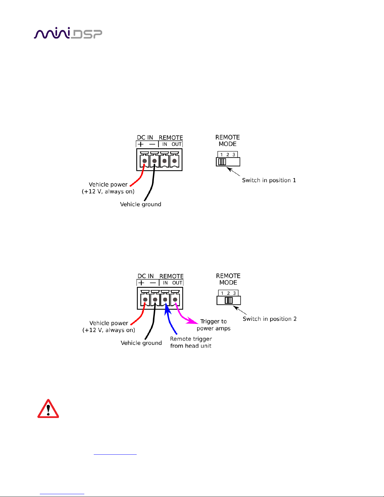
3.4.1 Powered on power (position 1)
To power on the C-DSP 8x12 DL whenever 12 V DC is applied to the DC IN terminals, set the REMOTE MODE
switch to position 1. Typically, power is provided from the main vehicle supply (always on).
3.4.2 Remote trigger (position 2)
To reduce battery drain, the remote trigger option should be used. To enable remote trigger, set the REMOTE
MODE switch to position 2. In this case, the C-DSP 8x12 DL is powered on when the voltage on the REMOTE IN
terminal exceeds 4 V DC. Typically, REMOTE IN is connected to the remote trigger output from the head unit.
In this mode, the REMOTE OUT terminal should be used to turn on the power amplifier(s). There is a time delay
between REMOTE IN going positive and REMOTE OUT going positive. This can be configured in the plugin – see
page 72.
Position 3 of the REMOTE MODE switch is reserved for future use. Do not set the switch to position 3.
PRELIMINARY
miniDSP Ltd, Hong Kong / www.minidsp.com / Features and specifications subject to change without prior notice 20
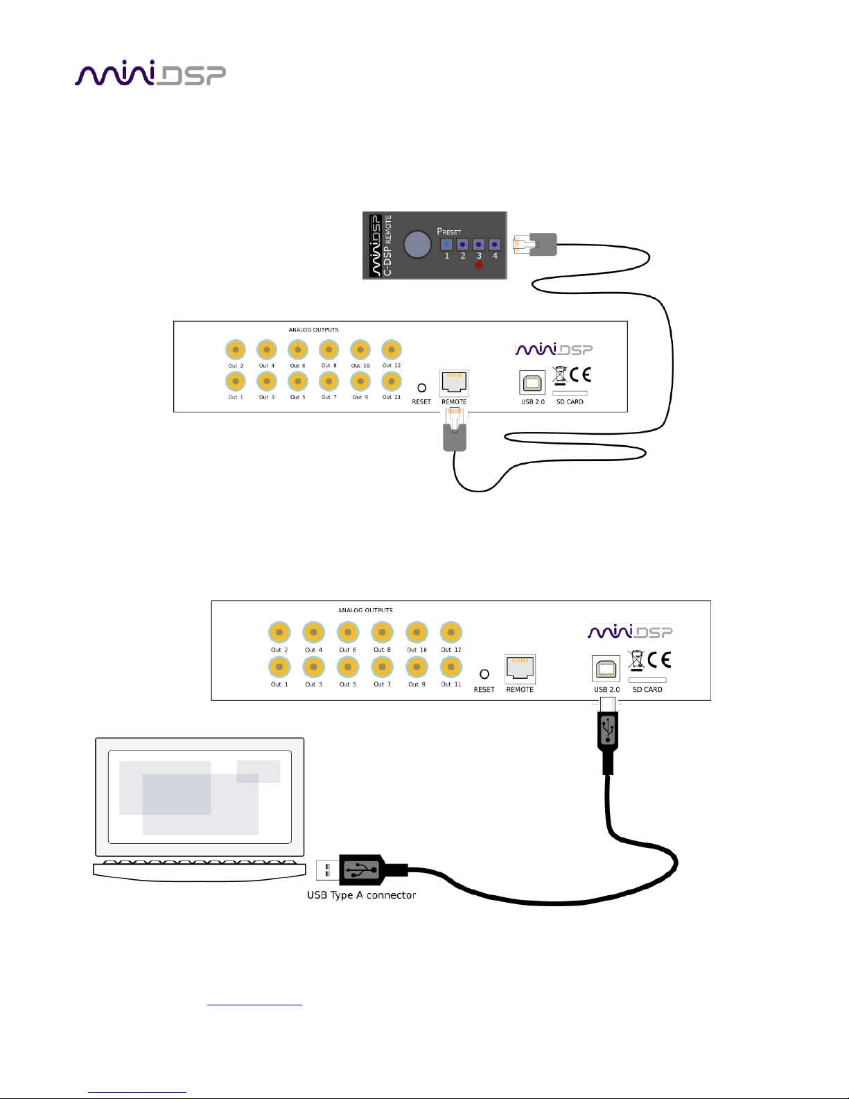
3.5 WIRED REMOTE
The wired remote can be positioned anywhere in the vehicle and is connected via the supplied RJ11 phone
cable. The plugs on each end simply plug into the base of the remote and into the rear panel of the C-DSP 8x12
DL. The wired remote also contains the receiver for infrared remote control.
3.6 USB
To configure the processor, connect its USB port to a USB 2.0 port on your computer using the supplied cable.
Note that USB is used only for configuration — audio data cannot be streamed to the processor over USB.
Configurations can also be loaded from a micro SD card – see page 68.
PRELIMINARY
miniDSP Ltd, Hong Kong / www.minidsp.com / Features and specifications subject to change without prior notice 21
4 PLUGIN OVERVIEW
The overall power of the C-DSP 8x12 DL comes not only from its comprehensive I/O but it’s merge of Dirac Live
processing with miniDSP’s powerful audio processing.
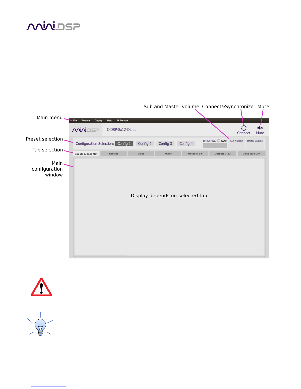
4.1 USER INTERFACE
This screenshot shows the C-DSP 8x12 DL plugin with the key areas highlighted:
During initial configuration of the processor, it is strongly recommended that any connected
amplification be muted or powered off.
We recommend that you do a “straight-through” Dirac Live calibration before attempting more
advanced configuration with the plugin. This way you can become familiar with Dirac Live
calibration and learn how the calibration algorithms work in your vehicle.
PRELIMINARY
miniDSP Ltd, Hong Kong / www.minidsp.com / Features and specifications subject to change without prior notice 22
4.2 SYNCHRONIZING WITH THE PROCESSOR
Communication with the C-DSP takes place over USB. Note that USB is used for control purposes only. Audio
data cannot be streamed to the processor over USB.
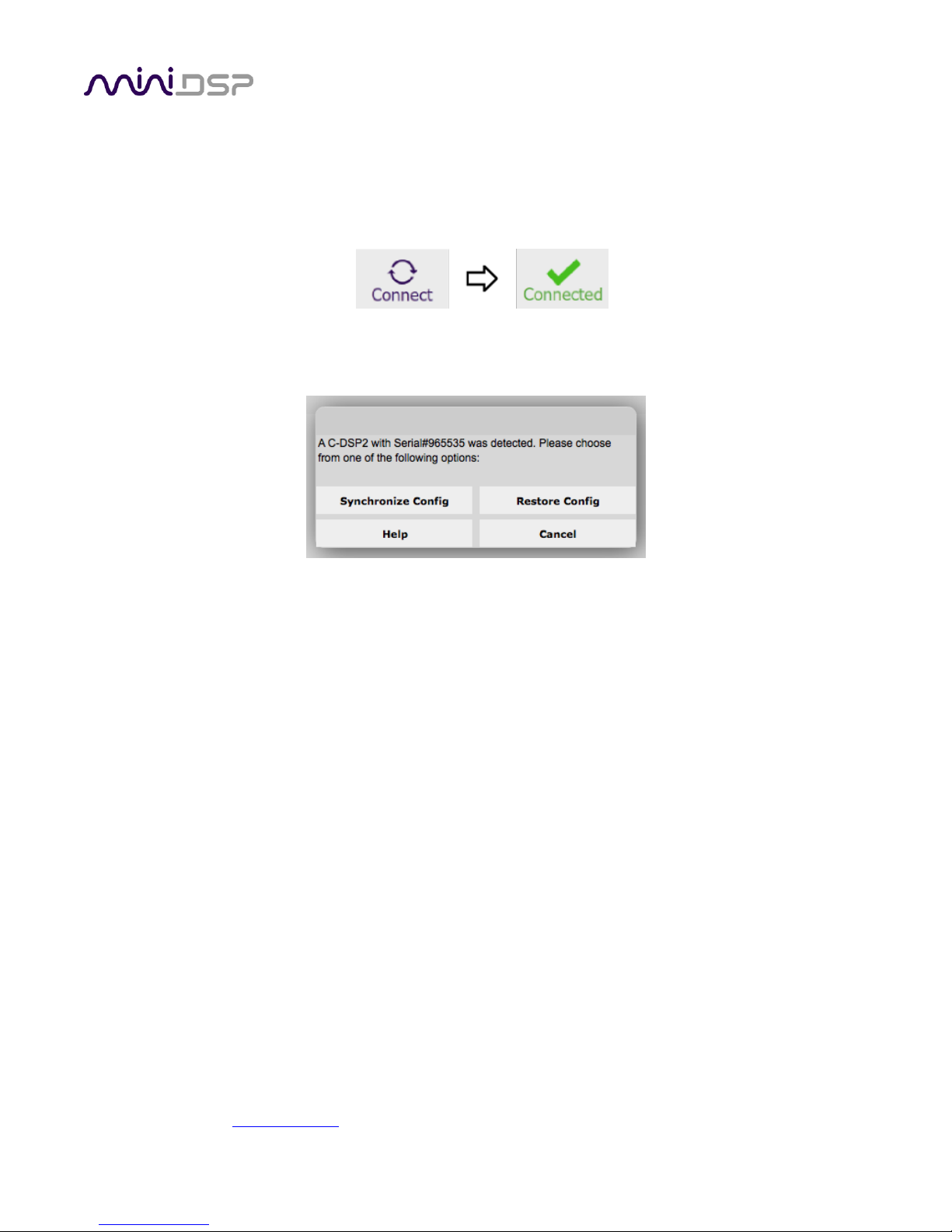
Ensure that the computer is connected to the processor via a USB 2.0 port. Then click on the Connect button:
The first time you connect, or if you have made any changes to any data in the plugin user interface, the
following dialog box will appear:
The options are:
Synchronize Config
Download the currently selected configuration into the corresponding configuration preset of the
processor. After downloading the configuration data, the plugin is in online mode and any changes to
processing parameters will be downloaded immediately in real time. That is, the user interface is now
“live.”
Synchronize and Upgrade
This is similar to Synchronize Config, but also upgrades the internal data of the processor. This option
may appear after downloading and installing an updated version of the plugin.
Restore Config
Restore the data in the currently selected configuration to the factory defaults. When using this
option, any connected output equipment should be muted or powered off until you have set the
configuration to a working state. Note that the configuration data currently stored in the processor will
be deleted.
Cancel
This option cancels the attempt to connect to the processor. The plugin will remain in offline mode.
PRELIMINARY
miniDSP Ltd, Hong Kong / www.minidsp.com / Features and specifications subject to change without prior notice 23
4.3 GLOBAL CONTROLS
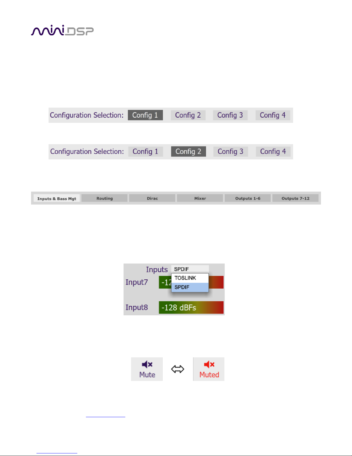
4.3.1 Configuration/preset selection
The set of data that controls the back-end processing is called a configuration. This includes crossovers,
parametric EQ and the routing matrix. It does not include the master volume or mute status.
Four configurations are stored onboard. The currently selected preset is indicated by a dark background:
To switch to a different preset, just click on the desired button:
4.3.2 Tab selection
For the selected configuration, this row of tabs selects the parameters to be display in the main display area.
4.3.3 Digital input selection
When the plugin is connected to the C-DSP 8x12 DL, the currently select digital input appears on the Inputs &
Bass Mgt tab, just above the level meters for channels 7 and 8. Click on it to pop up the selection menu and
select the desired input.
4.3.4 Master mute
The Mute button disables all audio output:
 Loading...